nea's response to queries · kindly confirm whether the armouring for the lt xlpe cable are...
TRANSCRIPT

Clause No Description Queries NEA Response
S.N. 2
1 The CPM shall effectively
communicate with main SCADA as
well as its peer FRTUs for fault
detection and control operations over
the same structure as the main
SCADA.
A control disable switch shall be
provided with each module with its
status indication:
For Peer to Peer Communication the FRTUs
should be connected over a reliable FO
network over a LAN. Kindly confirm that the
communication link between FRTUs will be
FO.
The Fault detection by each FRTU will be
based on the FPI (Fault Passage Indicator)
status monitored at each location. Please
confirm if any additional features are
envisaged.
Instead of a Individual Control Disable
Switch, a Local/Remote switch can be
provided in the FRTU to disable all Outputs.
The communication will be FO or RF or GSM network.
So the FRTU shall be compatible for use with both
mode of communication. FPI shall be as per the
specification.
The location and number of the control switch as
required shall be provided for the trouble free operation
and will be decided during detail engineering.
3
2 ii Detection of amperometric faults
adjustable for each feeder
FPI will be preferrably external mounted and shall be
as per specification.
3 iii Load current measurement on the line
fitted with a fault detector
FPI reset command should be provided for local and
remote operation.
NEA's Response to Queries
NEPAL ELECTRICITY AUTHORITY
PROJECT MANAGEMENT DIRECTORATE
FRTU Architecture :
Functions
FPI Status will be monitored for such faults.
The FPI reset command will also be
available. Please Clarify, FPI is external or
FRTU is required to have CT/PT inputs
directly to detect faults.

4 vi Energy supply and storage with 9-
hour autonomy in the event of mains
failure
This is not required separately for FRTU, if
the RMU is supplied with a Battery and
Battery Charger. Please confirm?
Confirm
5 vii It shall be possible to view
LBS/breaker status from the front
mimic of FRTU .
Kindly confirm if these indications will be
provided (wired) in RMU independent of
FRTU or these are required to be driven from
FRTU. If a MIMIC is required in FRTU, an
LCD display will have to be considered.
MIMIC is required in the FRTU.
6 xi The FRTU shall have remote or local
control mode switch on its front
panel.
This function is generally available on the
RMU. Not required on FRTU separately.
Confirm but if required during detail engineering shall
be provided at no additional cost to the employer.
7 In remote control mode This feature is provided on RMU Confirm
8 In local mode This feature is provided on RMU Confirm
9 DC Power Supply Battery with power supply will be provided
within RMU
Confirm
10 4.2 Measurement Archiving :
The minimum storage capacity shall
be 20000 measurements.
The data is archived on a Flash drive. The
Sizing of the drive will be finalized during
engineering stage.
Confirm
11 7.1 Diagnosis :
Protocol analyser: This analyser is
used to observe the frames exchanged
with the remote control centre to
facilitate maintenance operations.
Is this to be provided separately. If not included shall be provided seperately.
12 9 Switch Connection Please clarify. As per specification

13 10 List of Information to be provided > Pt 2,3 and 4 will be achieved by reading
values from MFM
> Pt 5, 6 and 7 are related to the Battery
Charger which is in ABB's Scope. All these
faults are required inform of Digital Inputs
from the Charger.
> UPS fault details to be confirmed by ABB
for I/O calculations
All the signals and information listed is to be provided.
14 11 FRTU should support following
future provisions
FRTU supports the PLC
programming/configuration. However a one-
time license is required for configuring this.
The same should be procured whenever
required.
As per specification
15 RMU Please confirm if supply of whole of SCADA
system to be made by the contractor or to be
connected to the SCADA system of NEA.
This is a turnkey contract all works required for
succesful completion, commissioning and operation
shall be responsibility of the contractor.
16
3 -Outdoor
The equipment shall be suitable for
mounting on galvanised steel
supporting stand and housed inside a
naturally ventillated all weather metal
kiosk
The unit to be suitable for Outdoor (Not
Kiosks) applications and can be used either as
a free standing unit or installed in compact
mini substation .The product can accomdate
further extension of breakers and isolators
depending on application.
As per the specification

17
Hermatically sealed metallic epoxy
/stainless steel enclosure for outdoor
RMU application
Stainless steel is the most preferred material
for Gas Insulated System because of its high
resistance to corrosive and humid
atmosphere. In case of fault in cable box, it is
easier to change a bushing. In case of epoxy
resin tank, the entire unit has to be scrapped.
This is against the philosophy of
interchangeability and flexibility at site.
Amendment Issued
18 5.2
Units should be constructed from
3mm thick hot rolled steel sheets
however SF6 enclosure are stainless
For the offered RMU, we provide 3mm
stainless steel tank containing all the live
parts and switching functions which is
Robotically welded with degree of Protection
IP67.This ensures a high level of reliability as
well as personal safety and a virtually
maintenance -free system . Outer enclosure 2
mm Galvatite sheet (which is more superior
to CRACA sheets) & Cable box covers with
2mm thick with degree of protection IP54 for
Outdoor application.
As per the specification
19 6.3
Three Numbers of continuous busbars
made up of EC grade tinned copper of
rating 630A shall be provided
All bus bars are encapsulated in SF6
environment & Type tested as per IEC, hence
tin plating is not envisaged.
Confirm
20 6.11.12Cable testing possible without
disconnection of cables
Offered RMU is with cable testing facility
from Cable Bushings without disconnecting
the cables & with opening of Cable Box
cover which is interlocked with Earth Switch.
Cable box cover will open only in Earth
position.
Confirm

21 6.12The auxilairy transformer will have
sufficient VA capacity
Please furnish VA Capacity of Auxiliary
transformer. In our opinion 500VA capacity
is sufficient
Will be decided during detail engineering after due
calculation
22 6.13.5
An automatic battery checking device
shall be provided to check battery’s
health and intiate a battery failed
alarm signal in case of battery
deterioration is detected
Please clarifyThe specified features as per technical specification
shall be provided
23 6.14.1
All the functions within the RMU
i.e.isolators/breakers should be fitted
with motor mechanism and closing
coil making it suitable to make it ON
from remote
For the offered design of RMU,closing coil is
not envisaged
The specified features as per technical specification
shall be provided
24 7.2.7Nominal operating gas pressure: 1.4
Bar abs 20Deg.C.
Nominal operating gas pressure: 0.05 Bar G.
20Deg.C.During DDE
25 7.5 Mechanism
The Circuit Breaker Mechanism is assembled
with stainless steel parts & not from MS as
MS parts will get rusty over a period of time
& fails to operate on fault thereby bypassing
the protection system leading to the failure.
Confirm
26 Mechanism has fuse tripping device
Not applicable since Protection circuit is with
self-powered Relay in conjunction with
Protection CT`s.
Confirm
27 6.13.4 dBattery shall have minimum life of
five years at 25Deg.C
Battery shall have minimum life of 2 years at
25 Deg.C as per recommendations of
manufacturer of battery
Please follow the technical specification
For HT 11 kV Cables

28For chapter 2 system
parameter
system parameter of rated short circuit
current is 25 kA for 3 sec.
For the required system parameter of rated short
circuit current of 25 kA for 3 sec, kindly clarify
whether it is applicable for all three cores
combined or for each individual cores of the HT
cable
As per IEC standard
29
Technical
specification : CL
No. 1.15 Metallic
screen
The required rated short circuit
current of 25 kV for 3 sec(i.e. 8.33 kA
for 3 sec for each individual core)
Please note the short circuit rating of 150 Sq.
mm shall be 8.14 kA for 3 Sec. Technically
this design of cable is not Feasible for
manufacturing.
As per IEC standard
30
Technical specification
: CL No. 1.15 Metallic
screen
The required rated short circuit current of
25 kV for 3 sec(i.e. 8.33 kA for 3 sec for
each individual core)
Please note the we shall meet the required short
circuit current for metallic screen only with the
help of the combination of copper wires and
copper tape, NO LEAD SHEATH SHALL BE
PROVIDED.
As per technical specification
31
Technical
specification: CL.NO.
1.2
_
Kindly clarify whether the required insulation
material is XLPE or TR- XLPE ( Three Retardant
XLPE)
As per technical specification
32
Technical
specification: CL.NO.
1.2
_
Kindly note that each cores shall not have
Polyethylene Sheath, a common inner covering
(sheath) of PVC type - ST2 shall be provided as
per applicable IEC/IS standard
As per IEC standard
For HV ABC Cable:
33
Technical specification
:Cl. NO. 3.0 Phase
Identification
Ribs shall be in rounded formIt shall be in triangular form as the constructional
diagram ennclosed for your ready reference.As per technical specification
For LT Power Cable
34Technical specification
: LT Power Cable_
UV Testing shall be applicable on the outer sheath
only. It shall not be applicable for insulation, as
only outer sheath of the cable shall be in direct
exposure of the sun light
As per technical specification

35Technical specification
: LT Power Cable_
Kindly note that the conductor for the LT power
cables shall be stranded compacted circular ( for 1
core cable) and stranded compacted sector shaped
(for multi core cable). Kindly confirm
As per technical specification
36
Technical specification
: LT Power Cable
clause 5
_
Kindly note that XLPE insulation shall not be
resistant to FIRE & OZON as XLPE doesnot
adheres those properties.
As per technical specification
37
Technical specification
: LT Power Cable
Clause 6
_Kindly note core identification shall be provided
as per apllicable IEC/IS standard.Confirm
38
Techincal specification
: LT Power cable
Clause 9
_Kindly confirm whether the armouring for the LT
XLPE cable are wire/strip or only round wireShall be decided during detail design engineering
For HV ABC cable
39
Techincal specification
: HT AB cable clause
6.5 table 1
_
Kindly note, the earth fault required for metallic
screen i.e. 2.14 kA for 1 sec can only be meet by
combination of copper tape in open helix
formtion.
As per IEC standard
RMU queries
40Technical specification
: scope clause No. 1
The unit shall be of 11 kV metal enclosed,
panel type , extensible and suitable for
indoor and outdoor application
RMU shall be outdoor type as per BOQ. Please
clarify of there is any requirement of RMU for
indoor application.
Shall be outdoor type

41
Technical
specification:
Application - outdoor
clause No. 3
Hermetically sealed metallic epoxy/
stainless steel enclosure for outdoor RMU
application
Metallized epoxy enclosure for tank is not
recommmneded for RMU.Please remove this
point. Tank is heart of RMU wherein all LBS and
VCB shall be enclosed inside the tank. Tank must
be made of non ferrite and non magnetic stainless
steel and must be robotically welded sealed for
life. We are provided 2.5 thick SS tank. Fabricated
part (support structure and outer enclosure shall be
made of 2 mm thick CRCA sheet)
Amendment Issued
42
Technical
specification:
Application - outdoor
clause No. 3
The manufacturers shall confirm the
normal current ratings mentioned in
technical data sheet (TDS) at 50 degreee
ambient without derating
RMU is rated for 630 A @ 40 deg C ambient.
Current deration shall be applicable @50deg C
derated current shall be 571A. Please confirm.
As per specification
43
Technical
specification: SF6 gas
interrupters clause No
4.2
SF6 gas interrupters
We are using Vaccum interrupters. Hence this
clause shall not be applicable for interrupters for
breaker.
Confirm
44
Technical
specification: SF6 gas
interrupters clause No
4.2
The vendor shall state in the proposal the
nominal SF6 gas filling pressure and
nominal fill temperature
1.4 bar@20deg C Confirm
45
Techincal specification
: SF6 gas annual loss
clause No. 4.2.1
The switchgear shall not remain energized
with load connected if there is no SF6 gas
inside the tank.
It is recommended not to perform make & break
operation in RMU in case of gas loss. It is
recommended to cut the supply from upstream
breaker
Confirm

46
Technical specification
: SF6 gas pressure
gauge/no-return valve
& low gas swithch
clause No. 4.2.2
A separate low pressure SF6 gas switch
shall be provided for low pressure alarm.
The low pressure switch is to be set to
operate at pressure which wll indicate loss
of SF6 within switchgear and will not
generate false alarms as the SF6 gas
pressure drops due to the ambient
temperature drop or change
There shall be NO contact in manometer which
shall be wired to terminal block. This can be
futher wired to SCADA panel for alarm. Note that
manometer is temperature compensated which will
indicate the pressure independent of ambient
temperature . In case of gas loss ( below 1.2 bar)
pressure will be indicated in red zone.
Confirm
47
Technical specification
:General structural and
mechanical constriction
clause No. 5.2
The overall design of the indoor
switchgear should be such that front
access only is required
RMU required is of outdoor type as per BOQ.
Please confirm whether outdoor RMU is also with
front access only or side & rear access is allowed
for outdoor RMU
As per specification
48
Thechnical
specification: General
structural and
mechanical
constrcution clause No.
5.2
The units should be constructed from 3
mm thick hot rolled steel sheets, however
SF6 enclosures are stainless
Fabricated part shall be made of 2 mm thick
CRCA sheet only. Please confirmAs per specification
49
Techincal specification
: General structural ans
mechanical
construction clause No.
5.2
The design of the unit should be such that
no permanent or hamful distortion occurs
either when being lifted by eyebolts or
when moved into position by rollers
It is recommended to lift the RMU with lifting
hooks only. It is not recommended to move the
position of RMU by roler, If surface is not smooth
Confirm

50
Technical specification
: General structural and
mechanical
construction clause No.
5.2
For out door RMUs weather proofing
process shall be carried out. Sheet metal
must be grit Blazed / thermally sprayed
and polyurethane paineted with about 70
micro thicknesses, to achieve outdoor
worthiness and corrosion proofness
The fabricated parts are pretreated using 7 tank
process and then coated by layer of zinc
phosphate. The parts are then painted using
polyester power coating paint with appropriate
thickness of 60-80 microns. This coating is
suitable for corrosivity class fo C1-C2 for outdoor
application. Grit/shot blasting of components shall
not be done. Plees clarify the corrosion class
As per specification
51
Techanical
specification : General
structural and
mechanical
construction clause No.
5.2
RMU enclosure must be shielded against
solar irradiation and tested for an ambient
of 50 degree centigrade without derating
of the equipment
RMU is rated for 630A @40 deg C amnient as per
IEC 62271-1. Current deration shall be applicable
@50 degC derated current shall be 571A. Please
confirm
As per specification
52
Techanical
specification : General
technical requirements
clause No. 6.1
It should be maintenance free, having
stainless steel robotically welded
enclosure for Indoor Rmu & hermetically
sealed metallized epoxy enclosure /
stainless stell enclosure for outdoor RMU
application
Metallized epoxy enclosure for tank is not
recommended for RMU please remove this point.
Tank is heart of RMU wherein all LBS and VCB
shall be enclosed inside the tank must of non
ferrite and non magnetic stainless stell and must
be robotically welded sealed for life. We are
provided 2.5 thick SS tank. Fabricated part (
support structure nd outer enclosure shall be made
of 2 mm thick CRCA sheet)
Refer Amendment
53
Techanical
specification : General
technical requirements
clause No. 6.1
Each RMU shall include its own power
supply unit (inclusing auxiliary power
transformer, maintenance, free batteries,
and batter charge), which shall provide a
stable power source for the RMU will
also supply 24V DC 500VA for FRTU
and other purposes.
Please confirm whether any metering is required
or not. If required, in which function it is required.
Metering where applicable is required. Metering is for
energy, current and voltage measurement.

54
Techanical
specification : General
technical requirements
clause No. 6.1
Monitor the local /remote position of Rmu
motorized ( in case if failure of motor )
manuall- operated switch that can be used
toenable and disable remote monitoring
Local/remote poistion shall be the part of FRTU
only (strongly recommended). It shall not be
provided in RMU. It will avoid any chance of
disabling FTRU by putting RMU in local mode.
Confirm
55
Technical specification
: General technical
requirements clause
No. 6.2
Necessary current senors / transformers
for protection and metering ( wherever
required ).
Nowehare in spec, it is mentioned to provde
metering moudle. Please re-confirm whether any
metering is required or not. If required, in which
fucntion it is required.
Refer answer of query no. 26
56
Technical specification
: General technical
requirements clause
No. 6.2
A PT panel including aux power
transformer for meadurement of system
voltage and for charging the batteries or
Aux supply from NEA line
Please confirm whether 230kV AC aux supply
shall be provided be NEA or aux power to be
derived form RMU through aux transformer?
Auxillary transformer shall be used for power supply
57
Technical specification
: Busbars clause No.
6.3
The three numbers of continuos busbaars
made up of EC grade tinned copper of
rating current 630A shall be provided
Bus bar shall be made of bare copper. Note that
bus bars are enclosed inside the SF6 insulated
sealed tanic. Tinned copper bus bar is not
required. We request NEA to accept the same. Bus
bar is rated for 630A@40 deg C ambient. Above
40 deg. Current deration shall be applicable.
Confirm for busbar material. Derating is not allowed.
Please provide as per specification.
58
Technical spefication :
Load break switch
clause NO 6.4
The operating mechanism shall be spring
assisted mechanism wih operating handle
for On/OFF
Operating mechanism of LBS shall be snap action
mechanism for LBSAs per specification
59
Technical spefication :
Load break switch
clause NO 6.4
The rated current isolator shall be 630A
continuous at Maximum ambient
temperatures. No derating shall be
allowed
We understand that LBS shall be motor operated
which means it is ready for remote operation. If
manually operated LBS required with provision of
motorization in future or is the requirement of
motorized LBS? Please clarify
LBS shall be used for remote operation. Motorized LBS
is required.

60
Technical spefication :
Load break switch
clause NO 6.4
The earthing swithch shall be operable
through the main circuit mechanism and
manual closing shall be driven by a
fastacting meachnism, indpendent of
operator action
RMU shall be rated for 630A @40 deg C ambient.
Above 40 deg. Current deration shall be
applicable.
Derating is not allowed.
61
Technical specification
: Earthing of isolators
and distribution
transformer breakers (
Earth switch ) clasuse
No. 6.5
Minimum number of operation at rated
current ( as per IEC 62271-100,102):
Mechanical endurance M2 (2000),
Electrical endurance-class E3
Please clarify this term "The earthing switch shall
be operable through the main circuit mechanism"Please provide as per specification
62
Technical specification
: Circuit breaker ( SF6
or Vaccum ) Clasue
No. 6.6
Minimum number of operations at rated
current ( as per IEC 62271-100,102) :
Mechanical endurance M2 (2000) ,
electrical endurance- class E3
We confirm the criteria of mechanical endurance
of 2000 operation which is termed as M1 class
instead of M2 class. RMU conforms to electrical
endurance class-E2 . Please clarity the requirement
of E-3 class endurance.
Please follow relevant IEC standard
63
Technical specification
: Circuit breaker ( SF6
or Vaccum ) Clasue
No. 6.6
All these relays shall be of 3 sec IDMT
characteristics, the O/C elements current
setting variable from 10% to 200% of CT
secondary ratings, and the E/F elements
having current setting variable form 10 to
40 %. The protection curves and all other
settings shall be adjustable from touch
panel
O/C setting from 20% setting from 200% and E/F
from 10% to 40% . Please confirm the transformer
rating.
Confirmed for setting of O/C and E/F.
64
Technical specification
: Bushing clause No,
6.7
It is preferable to have bushings
accessible from the rear side of the RMU
Bushing shall be accessible form front only.
Please ref clause no. 6.8 (front / rear/ side access
is aceptable)
As per specification

65
Technical specification
: Bushing clause No,
6.7
The cable boxes at each of the two ring
swithches suitable HV cables of size
3C*300 sq.mm and circuit breaker cable
suitable up to 3C* 400 sq. mm.
Please clarify whether it is single run cable or
double run cable. CB module is suitable for
3C*400sq.mm for single run cable only. In case of
double run cable in breaker module, Please clarify
why double cable is required in breaker module.
Generally double cable is required in LBS module
for loop-in loo-out double run cable up to 400 sq.
m can be provided in C module
Double cable may be required in select locations. This
shall be decided during detail design engineering.
66
Technical specification
: Extensible clause No.
6.10
Each combination of RMU shall have the
provision for extension by load break
isolators/ breakers in future, with suitable
trenching chamber, accessories and
necessary busbars. Extensible isolators
and curcuit breakers shall be individually
housed in separate SF6 gas enclosures.
Multiple devices inside single gas tank/
enclosure will not be acceptable.
Base RMU shall be extenible type where all LBS
and VCB shall be enclosed in single tank and shall
be suitable for coupling with other extensible unit
. Coupling LBS and VCB shall be housed in
single tank. Please confirm our understanding.
Confirm
67
Technical specification
: The characteristics of
the FP is shall incluse
clause No. 6.11.4
Phase fault thresholds configurable form
at least 100 to 800 A
Operating current short circuit : 200/ 300/ 400/
500/ 600/ 800/ 1000 AConfirm
68
Technical specification
: The characteristics of
the FP is shall incluse
clause No. 6.11.4
Earth fault thresholds configurable from
at least 20 to 200 A
Operating current of earth fault
10/20/30/40/50/60/80/100AAs per technical specification

69
Technical
specification: The
charavteristics of the
FPIs shall include
cause No.6.11.4
Fault current duration range configurable
from at least 40 ms to 100 ms in 20 ms
steps and further 100 ms to 300 ms in 50
ms steps
Available FPR response delay time is
40/60/80/160/200/300/500 ms. Please confirm the
make and model no. of FPI having mentioned
setting in specification.
Confirm
70Technical specification
: FPI clause No. 6.11.8
The conventional practice is to have N
numbers FPI where N is number of LBS
in a particular configuration of RMU
Please confirm whether FPI to be provided in each
LBS or no. of LBS-1As per specification
71
Technical
specification: FPI
clause No. 6.11.9
Units fully SCADA compatible.
Retrofitting at site possible at a later date.
Line switches ( Load break switches) as
well as T-OFF circuit breaker can be
operated by remote
Please clarify the SCADA Compatible. RMU to
be provided with mannual operation with future
provision of motorization or RMU to be provided
woth motor assembled in factory.
RMU is to provided with motor assembled in factory.
72
Technical Specification
: FPI clause No.
6.11.14
All live parts should be inside a
hermentically sealed metalized Epoxy
enclosure / stainless steel enclosure for
outdoor type RMU & 3 mm stainless steel
robotically welded enclosure for indoor
RMU
Tank thickness shall be 2.5 mm and we confirm
that same is suitable for required volume of gas
and we have type tested RMUs with this tank
thickness. We request NEA to accept the same.
As per specification
73
Technical specification
: Auxiliary transformer
clause No 6.12
FRTU (supplied by other with rating of
23oV AC, 1 A)
Please clarify whether FRTU shall be the part of
RMU or there is separate requirement of RMU &
FRTU wherein RMU & FRTU shall be supplied
by different vendors
Part of RMU and if seprately provided it shall be at no
additional cost to employer
74
Technical specification
: Auxiliary transformer
clause No 6.12
Receptacle (230V AC , 5A for powering
local test equipment's)
We understand that it is not the part of RMU.
Please confirm our understanding. It is considered as part of RMU
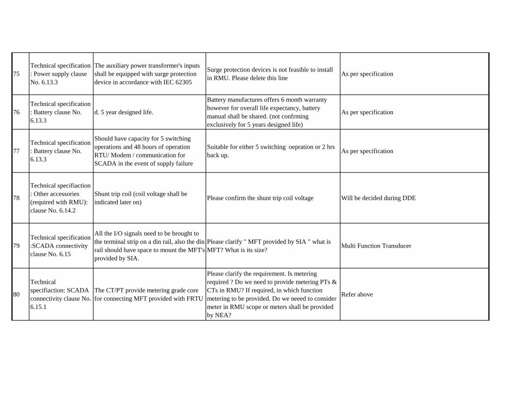
75
Technical specification
: Power supply clause
No. 6.13.3
The auxiliary power transformer's inputs
shall be equipped with surge protection
device in accordance with IEC 62305
Surge protection devices is not feasible to install
in RMU. Please delete this lineAs per specification
76
Technical specification
: Battery clause No.
6.13.3
d. 5 year designed life.
Battery manufactures offers 6 month warranty
however for overall life expectancy, battery
manual shall be shared. (not confrming
exclusively for 5 years designed life)
As per specification
77
Technical specification
: Battery clause No.
6.13.3
Should have capacity for 5 switching
operations and 48 hours of operation
RTU/ Modem / communication for
SCADA in the event of supply failure
Suitable for either 5 switching oepration or 2 hrs
back up.As per specification
78
Technical specifiaction
: Other accessories
(required with RMU):
clause No. 6.14.2
Shunt trip coil (coil voltage shall be
indicated later on)Please confirm the shunt trip coil voltage Will be decided during DDE
79
Technical specification
:SCADA connectivity
clause No. 6.15
All the I/O signals need to be brought to
the terminal strip on a din rail, also the din
rail should have space to mount the MFT's
provided by SIA.
Please clarify " MFT provided by SIA " what is
MFT? What is its size?Multi Function Transducer
80
Technical
specifiaction: SCADA
connectivity clause No.
6.15.1
The CT/PT provide metering grade core
for connecting MFT provided with FRTU
Please clarify the requirement. Is metering
required ? Do we need to provide metering PTs &
CTs in RMU? If required, in which function
metering to be provided. Do we neeed to consider
meter in RMU scope or meters shall be provided
by NEA?
Refer above

81
Technical specifiation :
techincal data clause
7.1
Impulse voltage withstand-95 kVp
Impulsse voltage withstand of NEA specs for 11
kV VCB panels calls for 75kVp only. Why for
RMU 95 kVp is insisted?
Change to 75 KVp
82
Technical
specification:
Mechanism clause No,
7.5
The mechanism provide independent
manual operation fo closing and opening
of the switch independent closing of the
earthing switch and dependent operating
of the earthing switch
closing and opening of eathing switch shall be
independent manual. ( for both LBS and Breaker
Function)
As per specification
83
Technical
specification:
Mechanism clause No,
7.5
The mechanism has fuse-tripping device Please clarify this terminology. As per specification
84
Technical specification
: FRTU architecture
clause No. 2
The central processing module shall be
suitable to handle all type of
communication protocals.
Apart from 60870-5-101/104 is there any other
communication protocol needed. Please clarify for
per-peer FRTU & FRTUs to main SCADA
communication network establishment shall be in
customer's scope
It is in the scope of contrator.
85
Technical specification
: FRTU architecture
clause No. 2
Control disable switch provide with each
module with its status indication so that
when the switch is put off the control
outputs shall be disable.
Please clarify for control disable switch, it is
local/remote switch or some thing else?Local/remote switch
86Technical specification
: Function clause No.3
Detection of amperometric faults,
adjustable for each feederPlease clarify this point.
Please follow specification and relevant international
standard
FRTU Queries

87Technical specification
: Function clause No.3
Load current measurement on the line
fitted with a fault detector
Please clarify who will be responsible for supply
to these sensors and where will it be mounted.
What will be the protocol of these sensors. Supply
of requirement sensors are not in FRTU scope of
supply or these sensors are mounted in FRTU,
Please confirm
Sensor are to be mounted in FRTU and is in
responsibility of the contractor.
88Technical specification
: Function clause No.3
It shall be possible to issue control
command form the front panel of the
FRTU with scurity button
Hardware push button with key shall be provided
on the front mimin to facilate the same . Please
confirm
Confirm.
89Technical specification
: Function clause No.3DC power supply
DC power supply of FRTU shall be included in
RMU as per clause no. 6.12 & 6.13Confirm
90
Technical specification
: Measurement
archiving clause No.
4.2
Each measurment can be configured to be
archived if required. A measurment
declared archived can be stored.
Each value data file shall be created separated and
stored.Confirm
91
Technical Specification
: communication
protocal clause No. 5.1
IEC 60870-5-101/104 protocol to transfer
information to control SCADA.
Please clarify which communication protocol is
required. Since both use different communication
prots like IEC 101 use RS132/RS485 and IEC 104
use Ethernet port . Same both use differnet modem
for remote communications.
IEC 104
92 General Road Restoration
Please confirm that statutory charges towards road
cutting & shall be reimbursed to bidders against
production of documentary evidence.
Confirm
93 General ROW issue
ROW acquisition and cost of ROW for substation
and line works is in the scope of NEA . Please
confirm
Confirm
Civil Work Queries

94 General Local items
Kindly confirm the tax process, beebfits & liablity
which we have when we will procure the supply
items & civil items from Nepal
Bidder shall bear all taxes like VAT,etc as per rules and
regulation of government of Nepal.
95
Technical
specification: Event
Transmission clause
No. 5.2
It shall be possible to configure each time-
stamped event to corresonds to the
appearance or disappearance of an
alarming event or an alarming closure
failure
we can confirm this event for tripping facility
interlock enable/ disable but for SCADA alarm
display, customer need to change in their SCADA
alarm enable/disable
As per specification
96
Technical
specification:
communication prots
clause No. 5.2a
One RS232 console port and for
connecting external modem.
Kindly clarify what this port shall be use for ?
What console are we referring to here? For
understanding, for FRTU & modem , ethernet port
are used for communication through IEC 104.Also
modem is having RS232 port.
Shall be provided if required
97
Technical specification
: Local
communnication
networks clause No. 6
The control unit shall have a Modbus
RS485 port for mommunication with the
station equipment /multi function
transducres.
Please clarify whether all the IEDs are with
modubus protocol only or is there any other
communication protocol
Please follow IEC 104
98
Technical
specification: disgnosis
clause No. 7.1
Measuremnet and status display : this
page is used to view in real time the TSS,
TSD and TM status for each switch
controlled by FRTU
Please clarify what is TSS, TSD & TM? Please refer to related international standard.
99
Technical
specification: disgnosis
clause No. 7.1
Protocol analyzer:
This is a licensed third party software. Need third
party tools for protocol analyzer . FRTU don’t
have in built facility of this . We can show data
log on RFTU web page. Same will be in customer
scope
Provide as per specification.
100
Technical
specification: switch
connection clause No.
7.5
switch connection Please clarify in which device , need fail safe
protection.During Detail Design Engineering

101 Technical specification Self healing grid logicKindly provide us your envisaged detailed logic
for this requiementDuring Detail Design Engineering
102
Technical
specification: scope
clause 1.1
LT distribution pillars made out of either
mild steel enclosure with SMC door or
complete enclosure of thermosetting
plastic
We recommend for use of (10SWG) CRCA/MS
doors powdered coated with enamel paint after 9
tank treatment which are more durable & have
longer life as compared with SMC doors and
continuosuly is use power grid & various power
utilities boards as a standard practice &
successfully working for a long time.
Confirm
103Technical specification
: standards clause 3.0
As per TS clause 3.0 standards: All
compenents used in the manufacture of
the pillars shall confirm to the relevant
IEC or equivalent internaltional standard.
All components used in the manufacture of the
pillars shall be confirm to IS/IEC as per their
manufacturing standard
Confirmed but equivalence has to be proved.
104
Technical specification
: Air circuit breaker
clause 5.2 Sr. No2
Air circuit breaker Sr. No. 2 Rated
frequency (5HzRated frquency (50Hz ) Confirm
NEA Response
105 As per design of the manufacturer
106 47.7 m/s
107It is attached as Annex to this clarification. It will be
used for transformers or line as necessary.
Where is the 9kV arc suppression coil for use? Where is it located?
In the tender document VolumeⅡ, Page 13, 5.2 Meteorological data, d) wind speed zone 4, please kindly
clarify the exact wind speed by how many meters per second?
Queries
LT feeder Pillar Queries
In the tender document Volume Ⅲ, the Item 11KV 3 phases dropout fuse set with all accessories suitable
for DT is not quite clear for the technical specification. Please kindly supply technical specification or
explain for this item. Is it used for transformer?

108Not mandatory during submission but may be required
after contract agreement.
109 Not available
110 Type Test
“All the cable types and sizes i.e.
items offered should have been fully
type tested as per IEC with
amendments at any internationally
accredited third party testing lab.”
“For each type and size the type test
shall be got carried out
independently.” as specified in clause
15 ,in page 74 of Volume II.
Can type test report for cables similar
structure used for biding documentsConfirm.
For Cables:
11kV XLPE POWER CABLE
Please kindly supply electronic Google map edition of the preliminary survey by the employer.
In the tender document VolumeⅡ, page 105 12.7 clause and page 110 10.7 clause, the bidder should
furnish the sample, we would like your kind office to confirm whether it is mandatory during the tender
submission? It will be rejected or not if the bidder can’t submit the sample?

111 The structure of metallic screen
The metallic screen is copper wire based
on “Helically wound copper wire
screening with equalising tape, shall be
provided on each conductor” as specified
in clause 1.2 ,chapter 3 of Volume II;
The metallic screen is copper tape based
on “Thickness of Copper Screen is
0.12mm” as specified in 22th of Page 214
and cross section drawing in Page 274 of
Volume II; The metallic screen is copper
wire and tape based on “A binder tape of
annealed plain copper shall be applied in
the form of an open helix over the copper
wire screen” as specified in clause 1.15 of
Page 58 of Volume II.
Which is the required metallic screen for this
project? (1) copper wire;
(2) copper tape;
(3) copper wire and tape.
As per specification
112Rated short circuit
current
The rated short circuit current of
11kV system is 25KA/3S as specified
in clause 1.3, chapter 2 of Volume II.
We need the rated short circuit current
of metallic screen for calculating the
thickness of metallic screen.
Is 25KA/3s the rated short circuit current of
metallic screen?As per specification
113 Oversheath
The oversheath is HDPE as specified in
clause 1.2 and 1.16 of Page 57 of Volume
II; The oversheath is PVC based on
“Nominal Thickness of PVC Outer
Sheath” as specified in clause 1.2 and
1.16 of Page 57 and cross section drawing
in in Page 274 of Volume II.
Which material is used for oversheath?
(1) HDPE;
(2) PVCHDPE

114 Amour
There are 4 kinds of materials used
for cable amour based on “The
armour of cables shall consist of
aluminum wires or strips. The
armoring shall beapplied such that the
minimum area of coverage shall be
90% and the gap betweenany two
armour strips/ wire shall not be more
than the width of strip/ diameter
ofarmour wire. The galvanized steel
strips/wire shall comply with the
requirements ofIEC with latest
amendments” as specified in clause
1.16 in Page 58 of Volume II .
Which material is used for amour?
(1) aluminum wires;
(2) aluminum strips;
(3) galvanized steel strips;
(4) galvanized steel wire
galvanized steel wire
LT XLPE POWER CABLE
115 Insulation colour
The insulation colour is black base on
“ All cores insulation shall be black
colored ” as specified as clause 6 in
Page 72 of Volume II
Can Natural be used for insulation colour Please follow specification
116 Amour
The amour is required based on
“Single core armoured cables -
dimensional details” as specified as
clause 2 in page 80 of Volume II;
The amour is not required based on “
LT XLPE CABLE S/C 630MMSQ ”
as specified as Schedule No.1 of
Volume III;
Does the single cable need amour? Yes

117 Hot deformation TestHot deformation Test is specified as
(e) clause 15 in Page 76 of Volume II.
Hot deformation Test is not applied in PE
oversheath. Can the test be deleted in type test?Please follow specification
118 Cable standard
“The insulation of the cable shall be
extruded cross-linked polyethylene
(XLPE) complying with appropriate test
requirements specified in section 3 of IEC
publication 60502” is specified in clause
2.5 of Volume II.There is not section 3 in
IEC 60502.
“The cable shall be manufactured and
tested in accordance with relevant NFC
Standard” is specified in clause 2.1 of
Volume II.
Can AS3599.1-2003 be used for cable
manufacturer?
If NFC standard must be used, please inform us
the name of NFC standard.
NFC 33 209. If AS is applied the equivalence shall be
proved.
119 Insulation colour
The insulation colour is black base on
“The conductor shall be insulated by
extruded black crosslinked polyethylene
(XLPE) material.” is specified as clause
2.3 in Page 88 of Volume II
Could we keep the color of insulation unchanged? Confirm.
120 Marking on the cable
“at the spacing of 5 meters. Every 2
meters of outer covering of the cable shall
also be embossed with length of the
cable.” is specified as clause 2.7 in Page
88 of Volume II
Length of the cable is paint on the cable, other
information is embossed on the cable. Is this OK?Confirm.
121
Ribbing on theexternal
surface of the
insulation
“The identification of the conductors shall
be provided by means of ribbing on
theexternal surface of the insulation.” is
specified as clause 23.0 in Page 89 of
Volume II.
Ribs occurs only on surface of the insulation
screen. Is this OK?Confirm.
HV AERIAL BUNDLED CONDUCTOR (ABC)

122The structure of
metallic screen
Earth fault current carrying capacity of
metallic screen
at 1 second (1 core) kA 2.14
at 3 second (1 core) kA 1.23
is specified as Table 1 in Page 91 of
Volume II. The cross-section of metallic
screen is 14.96mm2 after calculation. The
cross-section of 1 layer is 7.57mm2.
Shall we use 2 layers of Copper tape for metallic
screen?Confirm.
123 Cable standard
“The cable shall be manufactured and
tested in accordance with relevant
IEC or latest revision thereof or any
recognized international standards
that ensure at least a substantially
equal quality to the standards
mentioned above.” is specified as
clause 2.1 in Page 95 of Volume II.
There is no standard in IEC.
What’s the cable standard?Bidder is required to suggest the standard and its
equivalence to IEC
124 Marking on the cable
“at the spacing of 5 meters. Every 2
meters of outer covering of the cable
shall also be embossed with length of
the cable.” is specified as clause 2.5
in Page 95 of Volume II.
Information of the cable is paint on the cable,
Is this OK?As per specification
125The structure of
Aluminum conductor
“The lighting conductor shall be of
multi-strand round compact hard
drawn aluminum conforming to IEC
61089 with XLPE insulation.” is
specified as clause 2.7 in Page 95 of
Volume II.
The structure of 16mm2 Aluminum conductor
is uncompact usually. Is it using in this cable?As per specification
LV AERIAL BUNDLED CONDUCTOR (ABC)

126
Volume II-Section
6.4-Technical Data
Sheets & Drawings
We do not find the drawings of RMU, Please
provide the drawings of RMU or
Configuration list of VCB Panel and LBS
Panel..
RMU configuration shall be as per BOQ and
specification
127
Volume II-Section
6.3-Specification of
Equipment
G-Ring Main Unit-6.2(K)Please clarify whether the PT panel should be
provided for all RMUs.As per specification
According to the BoQ, Outdoor type 11 KV
SF6 type extensible and motorized one way
smart Ring
As per BOQ
Main Unit (RMU) complete with LB and
with FPI. Please clarify that the one way
smart RMU including one riser panel and one
load switch panel.
As per BOQ
129
Volume II-Section
6.3-Specification of
Equipment
G-Ring Main Unit-6.13-Power Supply-
6.13.4 Battery
Please clarify that the battery should have
capacity for 5 switching operations and 48
hours of operation of RTU / Modem /
Communication for SCADA in the event of
supply failure.
refer Above
130
Volume II-Section
6.3-Specification of
Equipment
G-Ring Main Unit-7-Technical data
According to the data sheet 7.1-2, impulse
withstand voltage is 95k V but in Section 6.4
this value is 75, Please clarify.
refer Above
131
Volume II-Section
6.3-Specification of
Equipment
M-Vehicle mounted single phase
modular cable fault locating
equipment
According to 4.2 “The CFL vehicle shall
have practical safety devices including
automatic checks inter-locking circuit”,
Please clarify that we need to provide the
CFL-equipment or the the whole CFL
vehicle.
Whole CFL vehicle
For other products:
128 Item E-5
Volume III-Schedule
No.1: Plant and
Equipment including
Mandatory Spares to
be supplied from
abroad

132
Volume III-Schedule
No.1: Plant and
Equipment including
Mandatory Spares to
be supplied from
abroad
Item-F-LT Feeder pillar-1, 2, 3
According to “metering arrangement on
incomer suitable for outdoor installation”
Please clarify that whether this specification
means the metering should be installed on the
door of panel.
Yes
133
Volume III-Schedule
No.1: Plant and
Equipment including
Mandatory Spares to
be supplied from
abroad
Item-F-LT Feeder pillar-4,5
According to “suitable for outdoor
installation”, we wonder to know that the
requirement of outdoor installation is applied
to MCCB or Panel. Please clarify
Panel
134
Volume III-Schedule
No.1: Plant and
Equipment including
Mandatory Spares to
be supplied from
abroad
Item-F-LT Feeder pillar-1,2,3,4,5
We would like to know whether the drawings
of Type A, B, C, D, E could be provided to
us. Please clarify
Will not be provided. Contractor is required to provide
the drawing for approval.

135
Volume III-Schedule
No.1: Plant and
Equipment including
Mandatory Spares to
be supplied from
abroad
Item-F-LT Feeder pillar-5
Whether the TPN is MCB and should be
3P+N; According to the BoQ that is 4P,but
according to the Specification the incomer is
4P and the outgoing is 3P.Please clarify.
Please follow BOQ
136
Volume II-Section
6.3-Specification of
Equipment
Item-H-Feeder pillar box-5.1.6
“Average minimum thickness of the sheet for
door shall be 3.15 mm for the Mini Pillar”.
The minimum thickness must be 3.15mm,
Please clarify.
Confirm.
138
Volume II-Section
6.3-Specification of
Equipment
G-Ring Main UnitWe did not find the technical data sheet for
FRTU, Please clarify.
TDS not available, equipment shall be as per
specification
139
Volume II-Section
6.3-Specification of
Equipment
G-Ring Main Unit-G.1.3/4
“The minimum storage capacity shall be
50000 events” “The measurement storage
conditions (configured individually) can be
combined. The minimum storage capacity
shall be 20000 measurements.” According to
the specification the storage is
50000&20000,that value is larger, Please
clarify
as per specification
137
“The Architecture shall include a central
processing module; and Digital and Analogue
Input/ Output (I/O) modules.” We would like
to know whether Digital Input/Output(I/O) is
accepted. Please clarify.
Both required
Volume II-Section
6.3-Specification of
Equipment
G-Ring Main Unit-G.1.2

140
Volume II-Section
6.3-Specification of
Equipment
G-Ring Main Unit-G.1.11
The FRTU must be capable to support PLC
programming. Whether the Single Chip
Micyoco is accepted, please clarify.
as per specification, decided during DDE
141 In Volume-II, section
6.3 and 6.4
In Volume-II, section 6.4 Page63,
cable drawing showed that metallic
screen is cooper tape. And in Volume-
II, Section 6.3, C-1.15, the metallic
screen shall be of plain copper wires,
applied a binder tape of annealed
plain copper.
We request you to confirm if the metallic
screen is copper wire with a binder tape of
annealed plain copper.
refer above
142 In Volume-II,
Section 6.3, C-1.16
In Volume-II, Section 6.3, C-1.16, the
armor of cables is aluminum wires or
strips. However, in
Volume-II, section 6.4 Page63, it
shows the armor is steel tape.
We request you to confirm which one we
should follow.refer above
143
Page No. 10 - 2.8.
Dismantling of
Existing 11 kV, l T
overhead system and
the street lights:
2.8.1 Dismantling of the selected
existing 11 kV system, LT overhead
system and theselected street lights
shall be carried out by the
Contractor as instructed by
theEmployer.
Who is responsible for stored dismantled
material (What is the distance of NEP
store from side location) and please confirm
the timing of dismantle of existing 11 KV
system and street light?
please refer PSR
144
What is the ratio of incentive if we wili
complete the work before time if we
complete 3 or 4 years?
no incentive

145
If work cannot be completed within reasonable
time due to any reason local lever disturbance and
delay of NEA ir that case who will bear the late
penalty.
please refer GCC
146What is condition for pre inspection of material
and HDD machines or supply presence required.
The equipment used for HDD shall be capable of
drilling at least 100m at one go. Please refer bid
document for other reqauirements of HDD.
147
Subcontractor has to understand whether
there is rock/stone underground as
rocks/stones have very bad effect on trechless
works. So, please kindly check whether
underground soil condiction data is available
and send the same if there is.
contractor has to assess
148
Project specific
requirement :1.1.3
Scope Activities:
7. Dismantling of Existing 11 kV
system including DTs, LT overhead
system and the street lights etc.
(required if any). Cost for such works
shall be included in the installation of
the
respective items.
kindly provide the approximate quantity for
items to be dismentled.During Detail Design Engineering

149 2.0 Detail Scope
2.1.3 The mapped details of the
underground utilities such as water,
sewerage, telecom
etc. may also be provided to the
Contractor for reference (wherever
possible),
however the contractor shall have to
prepare afresh/update the same by
carrying out
the mapping of the existing
underground utilities by GPS and
GPR (Ground
Penetrating Radar) equipment to
avoid the damage to any utility at the
time of
execution
Kindly confirm wheather 100 % route is to be
surveyed by GPR and if drawing is to be
preoared for all routes. Please also confirm
target depth of GPR survey.
confirm
15011. Specific
Requirements.
g. All RCC shall be of M-25 grade
(Minimum) with mixed design
conforming to relevant international
standard/BS. All Reinforcement steel
shall be of FE-500(Minimum) grade
conforming to International standards
/BS.
Kindly reconfirm the Grade of RCC is M 25. confirm
151In volumme III,
Section IV
Price schedule the quantity of OFC cable
is 125 km whereas the quantity of 40 mm
dia HDPE is 375 km.
What for the difference of quantity will be used .
Wheather this quantity will be erected or to be
handed over to store. Spare pipes shall be laid for future expansion
152In volume III, Section
IV
price schedule the combined quantity for
HT & LT cable is 405 km whereas the
quantity of 125 mm & 160 mm dia HDPE
is 650 km.
What for the difference of quantity will be used .
Wheather this quantity will be erected or to be
handed over. Spare pipes shall be laid for future expansion

153In volume III, Section
IV
Price schedule item 15. Construction of
double-decker Cubicle/Room for
providing Distribution Transformer
alongwith RMU and LT feeder pillar
including finsihing but excluding
excaation, RCC, Reinforcement, PCC etc
as above
Kindly provide the tentative size / drawing of the
building.
will be decided during DDE
154
Integration with existing systems, testing
and commissioning, along with the
support services including operation and
maintenance of the installed system for a
period of 3 years after the commissioning
of project.
Kindly confirm the details of activities to be
carried out as operation and maintainance for
three years.refer specification
155
Volume II Section
6.3 Specification of
equipment D1: HV
ABC 6: Bid
Documentation
Table 1
Please read Nominal at 2,3,4,6 and 7 as Minimum