nddot field sampling and testing manual 2019
TRANSCRIPT

FIELD SAMPLING AND TESTING MANUAL
Prepared by
NORTH DAKOTA DEPARTMENT OF TRANSPORTATION BISMARCK, NORTH DAKOTA
www.dot.nd.gov
MATERIALS AND RESEARCH DIVISION Matt Linneman
April 2008
June 2016 Revised March 2019 Revised

Intentionally Left Blank

8/30/2007
North Dakota Department of Transportation
Field Sampling and Testing Manual
NOTICE OF DISCLAIMER The North Dakota Department of Transportation (NDDOT) makes the “Field Sampling and Testing Manual” available on the NDDOT website.
Under no circumstances does NDDOT warrant or certify the information to be free of errors or deficiencies of any kind. NDDOT specifically disclaims all warranties, express or implied, including but not limited to the warranties of merchantability and fitness for a particular purpose.
The use of any of this information for work which is under contract with the NDDOT does not relieve the user from any obligations assumed by the contract, or from complete and proper fulfillment of the terms of the contract, nor does it entitle the user to compensation for damages of loss which could be attributed to such use.
This information is subject to change by NDDOT. Anyone relying on this information should satisfy himself/herself as to the most current version. The user agrees to accept all risks and consequences flowing from or related to the use, retention, distribution, alteration, or deletion of this information. NDDOT will in no instance be liable for any loss of profit or other damage, including but not limited to special, incidental, consequential, or other damages, even if apprised of the likelihood of such damages.

Intentionally Left Blank
______________________________________________________________________3/13/2019 Revised
FIELD SAMPLING AND TESTING MANUAL
TABLE OF CONTENTS
SECTION 100 GENERAL INSTRUCTIONS SECTION 200 EARTHWORK SECTION 300 BASES SECTION 400 BITUMINOUS PAVEMENTS SECTION 500 RIGID PAVEMENT SECTION 600 STRUCTURES SECTION 700 MISCELLANEOUS CONSTRUCTION SECTION 800 MATERIALS TESTING PROCEDURES FOR ALL TESTS ROUNDING PROCEDURES FOR DETERMINING SIGNIFICANT DIGIT RANDOM SAMPLING AND TESTING PROCEDURES QUALITY ASSURANCE PROGRAM FOR PRESTRESSED AND PRECAST CONCRETE PRODUCTS

Intentionally Left Blank

FIELD SAMPLING AND TESTING MANUAL
SECTION 100
GENERAL INSTRUCTIONS

Intentionally Left Blank

6/1/2016 Revised 100 1 of 1
SECTION 100 TABLE OF CONTENTS
Section 100 Outline 100.01 Introduction 100.02 Duties and Responsibilities 100.03 Procurement of Equipment and Supplies 100.04 Samples and Sampling Section 101 Abbreviations and Definitions Section 105 Control of Work 105.01 Inspection of Work Section 106 Control of Material 106.01 Description 106.02 General Methods 106.03 Independent Assurance Sample and Test Program

Intentionally Left Blank

100.01
Section 100
OUTLINE
100.01 INTRODUCTION.
This manual defines the procedures for field sampling, testing, inspecting, projects.
contents this manual the numbering sequence outlined in the Standard Specifications. As an example, test requirements Section 408 of Standard Specifications can be found in Section 408 this manual. This section gives required instructions methods in sampling, testing, and acceptance of Section 408 materials. this manual with the Standard Specifications.
NDDOT and FHWA created this manual. Associated General Contractors reviewed this manual before printing. Notify the Materials and Research Division of any errors or changes in this manual.
100.02 DUTIES AND RESPONSIBILITIES.
Materials and Research Division. The Materials and Research operates the supervision of the Materials and Research Engineer and participates in
the AASHTO Materials Reference Laboratory (AMRL), and the Cement and Concrete Reference Laboratory (CCRL) inspection programs.
State Highway Agency (SHA) is required by (CFR) Code of Federal Regulations Part to maintain an accredited Central Laboratory and to assure that all materials used highway and bridge construction conform to contract
Procedures to this are detailed this manual.
Materials and Research Division is a materials and testing resource. If a materials conflict occurs during project construction, notify Construction and Materials and Research Divisions. Materials and Research make a recommendation to the Construction Division.
Revised 4-97

B. District Materials Coordinator. The District Materials Coordinator is the construction materials specialist within the district and is responsible for proper materials sampling, testing, and specification compliance. The District Materials Coordinator is accountable to the District Engineer but must coordinate activities with the Materials and Research Division. Responsibilities include but are not limited the following:
1. Instruct district personnel in proper sampling and testing procedures. Assure that required field tests are in accordance with proper test procedures (Independent assurance testing).
3. Inspect and approve all field laboratories. 4. Issue and maintain field laboratory and survey equipment. 5. Conduct progress and final sampling, testing, and measu;ements. 6. For all federal-aid projects, prepare the FHWA •s required certification of
quality and quantity of each type of material and submit it to the District Engineer for his signature. Assure that the .. Materials Safety Data Sheet'" for hazardous materials is posted in the field laboratory where they are used.
C. Field laboratory Personnel. Obtain samples, either independently or from the Contractor, of all material requiring testing for quality control or acceptance. Perform tests, document test results, complete paper work, and inform the Project Engineer/Manager of test results. Test as much of the sampled materials in the field laboratory as possible. Perform all work in accordance with procedures set forth in this manual.
D. Consultants. Follow the procedures outlined this manual and directives of the District Engineer. Advice and/or direction is available from the same sources that are open to Department personnel.
Independent laboratories. Perform material testing for the Department using the Department's specifications and testing procedures. Provide certifications of all test results and, on request, allow inspection of the laboratory by representatives of the Department.
100.03 PROCUREMENT OF EQUIPMENT AND SUPPLIES.
office maintains a complete stock of testing equipment, sample containers, forms, and other supplies relating to material quality control. Request supplies from the District Materials Coordinator. To keep district inventory levels at a minimum and yet have ample supply when needed, each Project Engineer/Manager needs to anticipate well in advance and keep Materials Coordinator fully informed.

100.04 SAMPlES AND SAMPUNG.
General. The Project Engineer/Manager approves sampling and testing methods used at project Contract Documents indicate the test method used.
Appendix F contains the required number of district, and Materials and Research tests.
Use field numbers to identify samples submitted to the District and Materials and . Accompany samples submitted District or Materials and Research Division with field sample test results. District Materials Coordinator field test results with from
district laboratory Materials Research report showing the comparison.
Information to Be Submitted with Samples. Sample cards and tag envelopes may be obtained the district office. Appendix D has information on, and examples of, these cards.
When submitting samples, make out a sample card, place it in a tag envelope, seal the envelope, and it securely to the sample. For questions about information required on the sample card, contact the District Laboratory. Report all pit location information by section, township, range, and by the
name. testing on card. Add additional information the back of the card.
C. Packing of Samples. Obtain containers for all materials at any district office through the District Materials Coordinator. Ship all samples in these approved containers. Ship asphalt cements and cutback oils in metal cans. Ship emulsified asphalt in plastic bottles or plastic pails. Securely fasten the lids on all containers used to ship liquid materials to prevent leakage. Mark packages containing these samples .. Liquid Handle with Care... samples of other materials in pails or sacks (i aggregate samples) or boxes (i.e., cores} and securely seal. To prevent injury, keep all shipping containers as light as practicable.
Carefully handle concrete cylinders place them transport vehicle so that they do not touch each other or any other hard object. Separate concrete cylinders by a soft material and load them carefully to avoid damage. Protect concrete cylinders from freezing hot

Authorized
Yield
Cement
Unit of Water
Face
Particles
Thin or Elongated pieces
Fractured Material
Compression Test
Test
Section 101
ABBREVIATIONS & DEFINITIONS
Central lab, District Lab, State Field Lab, approves.
lab the engineer
lb/cu
of samples taken a single, for testing.
manual as feet
surface constituting an area equal to at least % of the largest cross-sectional area particle. A fractured face is caused either by mechanical means or by nature. Natural fractures to be accepted must be similar to fractures produced by a crusher.
coal. Includes clay, soft iron oxide, and other friable material.
Maximum thickness less than 1 the maximum width, or more than three times the maximum
aggregate crushed to a smaller size from a larger size. aggregate retained on a 5k'" to produce aggregate of .. or less size.)
Two Concrete Cylinders cast the same sample.
Concrete Compression tests are cast on the project site and cured for 28 conditions. Average of two cylinders.
on a set under laboratory
Compression tests are on a set cast on the site and 7 days under laboratory conditions. Average of two cylinders.

Section 105
CONTROl OF WORK
The Standard Specification Sections; 1 05 on as it
1 INSPECTION WORK.
the field to accepted by Inspect as soon as possible after
material be defective, regardless of previous
If not used immediately, give approved materials another careful visual Before decide materials
a certification) that have deteriorated or quality.

Section 106
6/1/2016 106 1 of 3
Section 106 Control of Material
106.01 Description The following NDDOT Standard Specifications for Road and Bridge Construction sections give direction on control of work as it pertains to materials: 106.01, “General Methods of Materials Acceptance;” 106.03, “Samples, Tests, Cited Specifications;” 106.04, “Storage of Materials;” 106.07, “Rights In and Use of Material Found in the Work;” 106.08, “Department-Furnished Material;” and 106.09, “Buy American Products.” The following contains additional information pertaining to materials. 106.02 General Methods
• For each project keep a materials file containing copies of all laboratory tests, field tests, inspection reports, and certifications.
• All sampling and testing is conducted at the frequencies outlined throughout this manual. The specified frequencies are the minimum required for the project. The Engineer may increase sampling and testing at any time to verify the quality of the material.
• To ensure bias is eliminated from the sample selection process, sampling must be from random sample locations. The Engineer may utilize the random number table found in this manual or any other common method they find acceptable.
• At sufficient intervals, check the number of samples submitted to the laboratory, certifications, inspection reports, and number of field tests to be certain all materials used have the required supporting documents.
• SFN 10072, “Aggregate Quality Test Summary” should be posted on the project and used to record the results of all tests performed at an authorized laboratory. At the completion of the project, submit the original copy of this form to the District Materials Coordinator for review, approval, and distribution.
• If the Engineer waives the requirements for sampling and testing, or certification of compliance under the guidelines established in Section 106.01, “General Methods of Materials Acceptance,” of the NDDOT Standard Specifications for Road and Bridge Construction, the materials accepted under these conditions must be listed on SFN 10110, “Project Engineer’s Report on Materials Acceptance.”
• When the Engineer waives the requirements for sampling and testing materials or choses to use non-conforming materials, justification must be attached to SFN

Section 106
6/1/2016 106 2 of 3
10110. The justification must include, but may not be limited to, the consultation of the Materials and Research, Design, and Bridge Divisions.
• Specifications require the submittal of shop drawings for specified construction components. Shop drawings are required for some items such as pre-stressed beams, structural steel, lighting, traffic signal components, etc.
• The Contractor submits a minimum of two sets of shop drawings to the Engineer. It is the Engineer’s responsibility to send the drawings with a transmittal letter to the construction office for review and approval. If the project is a non-NDDOT engineered project, send the drawings and transmittal letter to the County or Consultant in charge of the project. Indicate in the transmittal letter if the shop drawings are for a project where a Critical Path Method (CPM) is specified. Components covered by shop drawings do not need certification unless required by specifications or plan notes.
106.03 Independent Assurance Sampling and Testing Program
The Independent Assurance (IA) Sampling and Testing Program is a major element of NDDOT’s Materials Quality Control Program. It is intended to ensure that test data derived from project acceptance testing is reliable by providing an independent check of test results and equipment. The program includes observations of project sampling and testing, split sample testing, equipment checking, and documentation.
The IA program is mandated by the Federal Highway Administration (FHWA). The purpose is to confirm the reliability of the test results obtained in the acceptance sampling and testing program. This is accomplished by observing sampling and testing procedures, as well as obtaining split portions of acceptance samples. Split samples are tested using equipment and testing personnel different from those used for acceptance testing. The test results are then compared to the acceptance test results. If these test results do not correlate, follow-up actions are taken to discover and correct the deficiencies.
The IA will evaluate the sampling and testing personnel and equipment of the NDDOT. The program covers sampling procedures, testing procedures, and testing equipment. The testing equipment will be evaluated by calibration checks, split samples, or proficiency samples. Testing personnel will be evaluated by observation, review of the control charts and documentation, and split samples.
An IA program is required of all states by the FHWA for all federal aid projects. The states develop their own program content using FHWA prescribed guidelines. FHWA concurrence with the IA is necessary before implementation by the state. It is NDDOT policy to apply the program to all federal aid projects, including Local Public Agencies on the NHS system.

Section 106
6/1/2016 106 3 of 3
Management of this program is at the District Materials Coordinator level and is the responsibility of the Materials and Research Engineer. All IA is independent of project management activities, however close cooperation between the two is essential. It is also particularly important that project personnel appreciate the importance of the IA and cooperate fully to accomplish its intended purpose.
The specific guidelines relative to the sampling and testing undertaken in this program are not described here. All areas requiring IA are designated throughout this manual.

FIELD SAMPLING AND TESTING MANUAL
SECTION 200
EARTHWORK

Intentionally Left Blank

______________________________________________________________________3/13/2019 Revised 200 Page 1 of 1
SECTION 200 TABLE OF CONTENTS
Section 203 Excavation and Embankment 203.01 Description 203.02 Excavation 203.03 Embankment – Acceptance Samples and Tests 203.04 Independent Assurance (IA) Samples and Tests Section 210 Structural and Channel Excavation, Foundation Fill and Preparation 210.01 Description 210.02 Excavation 210.03 Acceptance Samples and Tests 210.04 Independent Assurance (IA) Samples and Tests Section 230 Reshaping Roadway and Subgrade Preparation 230 Description 230.1 Acceptance Samples and Tests 230.2 Independent Assurance Samples and Tests Section 234 Stabilized Subgrade 234 Description 234.1 Acceptance Samples and Tests 234.2 Independent Assurance Samples and Tests Appendix 200-A Consultant Use of Nuclear Gauges for Compaction Control Reference Forms: DOT 13942 Conversion Chart for Speedy Tester SFN 2454 Density Test Worksheet – Volume Measure SFN 9987 Aggregate Sample Worksheet SFN 10063 Moisture-Density Relationship Tests SFN 59724 Sand Cone Correction Factor SFN 59725 Density Test Worksheet – Sand Cone Method All test procedures used within and referred to in this section can be found under “Testing Procedures” of this manual. Form examples at end of section are for “Reference Only.” Use the most current available forms on the NDDOT website only.

Intentionally Left Blank

Section 203
______________________________________________________________________6/1/2016 203 1 of 4
Section 203 Excavation and Embankment
203.01 Description.
This work consists of the excavation, haul, placement, disposal, and compaction of embankment material.
203.02 Excavation. No testing required. 203.03 Embankment – Acceptance Samples and Tests.
A. Engineer Responsibility.
The Engineer will collect material and conduct testing to verify the material meets the requirements of ‘Compaction Control’ in Section 203.04.E.2 of the NDDOT Standard Specifications for Road and Bridge Construction.
1. Compaction Control, Type A.
Table 203-1 shows test method and frequency for embankment compaction control.
Table 203-1
Test Frequency ND T 180 or ND T 99, “Moisture-Density Relations of Soils (Multi-Point)”
1 compaction curve for each change in soil.
ND D 2167, “Density and Unit Weight of Soil in Place by the Rubber Balloon Method,” or ND T 191, “Density of Soil In-Place by the Sand Cone Method”
1 test per 1,500 feet of compacted roadway per 12” lift.
ND T 265, “Laboratory Determination of Moisture Content of Soils;” or ND T 217, “Determination of Moisture in Soil by Means of Calcium Carbide Gas Pressure Tester (Speedy);” or ND D 4643, “Microwave Method of Drying Soils”
1 test per 1,500 feet of compacted roadway per 12” lift.
Sample locations will be randomly selected by the Engineer.

Section 203
______________________________________________________________________6/1/2016 203 2 of 4
The results of the in-place density and moisture tests are compared to the appropriate moisture density curve derived from the ND T 180 or ND T 99 testing. Compute the ND T 180 or ND T 99 on SFN 10063, “Moisture-Density Relationship Tests” worksheet. The in-place density and moisture tests are recorded on SFN 2454, “Density Test Worksheet – Volume Measure,” or SFN 59725, “Density Test Worksheet – Sand Cone Method.”
2. Compaction Control, Type B.
No testing required.
3. Compaction Control, Type C.
No testing required.
B. District Materials Coordinator Responsibility. Reserved.
C. Materials and Research Responsibility.
Reserved.
203.04 Independent Assurance (IA) Samples and Tests.
A. Engineer Responsibility. Conduct IA tests on split samples taken by the District Materials Coordinator. Testing performed will be as directed by the District Materials Coordinator.
B. District Materials Coordinator Responsibility.
The District Materials Coordinator will obtain these samples and conduct these tests. Soils or soil-aggregates tested for moisture-density relations will be an equal split sample from the Engineer. In-field IA testing will be conducted next to the field test using the same method. Table 203-2 shows test method and frequency for embankment compaction control, Type A, for IA.

Section 203
______________________________________________________________________6/1/2016 203 3 of 4
Table 203-2 Test Frequency ND T 180 or ND T 99, “Moisture-Density Relations of Soils (Multi-Point)”
1 compaction curve for each three miles of roadway, or a minimum of 1 test per 200,000 C.Y.
ND D 2167, “Density and Unit Weight of Soil in Place by the Rubber Balloon Method,” or ND T 191, “Density of Soil In-Place by the Sand Cone Method”
1 density test for each three miles of roadway, or a minimum of 1 test per 200,000 C.Y.
ND T 265, “Laboratory Determination of Moisture Content of Soils,” or ND T 217, “Determination of Moisture in Soil by Means of Calcium Carbide Gas Pressure Tester (Speedy),” or ND D 4643, “Microwave Method of Drying Soils”
1 moisture test for each three miles of roadway, or a minimum of 1 test per 200,000 C.Y.
Compute the ND T 180 or ND T 99 on SFN 10063, “Moisture-Density Relationship Tests” worksheet. The in-place density and moisture tests are recorded on SFN 2454, “Density Test Worksheet – Volume Measure,” or SFN 59725, “Density Test Worksheet – Sand Cone Method.”
Engineer and District Materials Coordinator will compare the test results for IA tolerance in Table 203-3.
Table 203-3
Test Tolerance ND T 180 or ND T 99, “Moisture-Density Relations of Soils (Multi-Point)”
± 4 lbs. cu. ft. (MDD) ± 1.5 (OM)
ND D 2167, “Density and Unit Weight of Soil in Place by the Rubber Balloon Method,” or ND T 191, “Density of Soil In-Place by the Sand Cone Method”
± 5 lbs. cu. ft.
ND T 265, “Laboratory Determination of Moisture Content of Soils,” or ND T 217, “Determination of Moisture in Soil by Means of Calcium Carbide Gas Pressure Tester (Speedy),” or ND D 4643, “Microwave Method of Drying Soils”
± 2.0

Section 203
______________________________________________________________________6/1/2016 203 4 of 4
If the initial IA testing is not within specified tolerances, the Engineer shall obtain an additional sample for testing under the observation of the District Materials Coordinator.
The Engineer and District Materials Coordinator shall conduct equipment checks and review testing procedures. This will continue until the differences are resolved.
C. Materials and Research Responsibility.
Reserved.

Section 210
_________________________________________________________________6/1/2016 210 1 of 4
Section 210 Structural and Channel Excavation, Foundation Fill and Preparation
210.01 Description.
This work consists of excavation as defined in the plans. 210.02 Excavation. No testing required. 210.03 Acceptance Samples and Tests.
A. Engineer Responsibility.
The Engineer will collect material and conduct testing to verify material meets the requirements of Section 210.03.B and 714.04.A.7, 8 of the NDDOT Standard Specifications for Road and Bridge Construction. Table 210-1 shows test methods and frequency for compaction control.
Table 210-1
Tests Frequency ND T 180 or ND T 99, “Moisture-Density Relations of Soils (Multi-Point)”
1 compaction curve for each change in material.
ND D 2167, “Density and Unit Weight of Soil in Place by the Rubber Balloon Method,” or ND T 191, “Density of Soil In-Place by the Sand Cone Method”
1 test per 1 foot in elevation.
ND T 265, “Laboratory Determination of Moisture Content of Soils,” or ND T 217, “Determination of Moisture in Soil by Mean of Calcium Carbide Gas Pressure Tester (Speedy),” or ND D 4643, “Microwave Method of Drying Soils”
1 test per 1 foot in elevation.
Sample locations will be randomly selected by the Engineer.
The results of the in-place density and moisture tests are compared to the appropriate moisture density curve derived from the ND T 180 or ND T 99 testing.
Compute the ND T 180 or ND T 99 on SFN 10063, “Moisture-Density Relationship Tests” worksheet. The in-place density and moisture tests are

Section 210
_________________________________________________________________6/1/2016 210 2 of 4
recorded on SFN 2454, “Density Test Worksheet – Volume Measure,” or SFN 59725, “Density Test Worksheet – Sand Cone Method.” Table 210-2 shows test method and frequency for aggregate placed.
Table 210-2
Test Frequency ND T 27, “Sieve Analysis of Fine and Coarse Aggregates”
1 test result per 2,500 C.Y.
ND T 11, “Materials Finer Than No. 200 Sieve in Mineral Aggregates by Washing”
1 test result per 2,500 C.Y.
NDDOT 4, “Percentage of Fracture Particles in Coarse Aggregate”
1 test result per 2,500 C.Y.
ND T 113, “Lightweight Pieces in Aggregate” 1 test result per 2,500 C.Y.
Compute the sieve analysis results on SFN 9987, “Aggregate Sample Worksheet.” Results are recorded on SFN 10072, “Aggregate Quality Test Summary.”
B. District Materials Coordinator Responsibility.
Reserved.
C. Materials and Research Responsibility.
Reserved.
210.04 Independent Assurance (IA) Samples and Tests.
A. Engineer Responsibility.
Conduct IA tests on split samples taken by the District Materials Coordinator. Testing performed will be as directed by the District Materials Coordinator.
B. District Materials Coordinator Responsibility. The District Materials Coordinator will obtain these samples and conduct these tests. These samples will be an equal split sample from the Engineer.

Section 210
_________________________________________________________________6/1/2016 210 3 of 4
Samples will be obtained and split according to ND T 2, “Sampling of Aggregates,” and ND T 248, “Reducing Samples of Aggregate to Testing Size.” Soils or soil-aggregates tested for moisture-density relations will be an equal split sample from the Engineer. In-field IA testing will be conducted next to the field test, using the same method. Table 210-3 shows test method and frequency for IA.
Table 210-3
Test Frequency ND T 180 or ND T 99, “Moisture-Density Relations of Soils (Multi-Point)”
1 compaction curve for each three miles of roadway, or a minimum of 1 test per 200,000 C.Y.
ND D 2167, “Density and Unit Weight of Soil in Place by the Rubber Balloon Method,” or ND T 191, “Density of Soil In-Place by the Sand Cone Method”
1 density test for each three miles of roadway, or a minimum of 1 test per 200,000 C.Y.
ND T 265, “Laboratory Determination of Moisture Content of Soils,” or ND T 217, “Determination of Moisture in Soil by Mean of Calcium Carbide Gas Pressure Tester (Speedy),” or ND D 4643, “Microwave Method of Drying Soils”
1 moisture test for each three miles of roadway, or a minimum of 1 test per 200,000 C.Y.
ND T 27, “Sieve Analysis of Fine and Coarse Aggregates”
Minimum 1 test result per project.
ND T 11, “Materials Finer Than No. 200 Sieve in Mineral Aggregates by Washing”
Minimum 1 test result per project.
NDDOT 4, “Percentage of Fracture Particles in Coarse Aggregate”
Minimum 1 test result per project.
ND T 113, “Lightweight Pieces in Aggregate” Minimum 1 test result per project.
Compute the ND T 180 or ND T 99 on SFN 10063, “Moisture-Density Relationship Tests” worksheet. The in-place density and moisture tests are recorded on SFN 2454, “Density Test Worksheet – Volume Measure,” or SFN 59725, “Density Test Worksheet – Sand Cone Method.” The Engineer and District Materials Coordinator will compare the test results for IA tolerance in Table 210-4.

Section 210
_________________________________________________________________6/1/2016 210 4 of 4
Table 210-4
Test Tolerance ND T 180 or ND T 99, “Moisture-Density Relations of Soils (Multi-Point)”
± 4 lbs. cu. ft. (MDD) ± 1.5 (OM)
ND D 2167, “Density and Unit Weight of Soil in Place by the Rubber Balloon Method,” or ND T 191, “Density of Soil In-Place by the Sand Cone Method”
± 5 lbs. cu. ft.
ND T 265, “Laboratory Determination of Moisture Content of Soils,” or ND T 217, “Determination of Moisture in Soil by Mean of Calcium Carbide Gas Pressure Tester (Speedy),” or ND D 4643, “Microwave Method of Drying Soils”
± 2.0
ND T 27, “Sieve Analysis of Fine and Coarse Aggregates,” and ND T 11, “Materials Finer than No. 200 Sieve in Mineral Aggregates by Washing”: No. 4 sieve and larger No. 30 sieve No. 200 sieve
±5 ±3 ±2
NDDOT 4, “Percentage of Fracture Particles in Coarse Aggregate”
±5
ND T 113, “Lightweight Pieces in Aggregate” ±2
If the initial IA testing is not within specified tolerances, the Engineer shall obtain an additional sample for testing under the observation of the District Materials Coordinator.
The Engineer and District Materials Coordinator shall conduct equipment checks and review testing procedures. This will continue until the differences are resolved.
C. Materials and Research Responsibility.
Reserved.

Revised 1/24/2012 230
230 1
SECTION 230
RESHAPING ROADWAY AND SUBGRADE PREPARATION
230 DESCRIPTION
This work consists of scarifying, shaping, compacting, and maintaining the subgrade, or reshaping an existing roadway before constructing a base, or surface course.
230.1 ACCEPTANCE SAMPLES AND TESTS
Field Laboratory Testing: The Engineer or Representative conducts a minimum of one moisture and density test for each compacted lift per 1500 feet of roadway. Conduct moisture test according to AASHTO T 217, “Determination of Moisture in Soil by Means of Calcium Carbide Gas Pressure Moisture Tester (Speedy).”* Conduct the density test according to ASTM D 2167, “Density and Unit Weight of Soil in Place by the Rubber-Balloon Method,” or AASHTO T 191, “Density of Soil In-Place by Sand-Cone Method.” Record information on SFN 2454, “Density Test Worksheet – Volume Measure,” or SFN 59725, “Density Test Worksheet – Sand Cone Method.” Conduct additional tests at locations as directed by the Engineer or Representative.
If work consists of embankment widening, then testing shall be conducted on each side of roadway or embankment that is widened. Each widened portion shall be considered a separate roadway.
230.2 INDEPENDENT ASSURANCE (IA) SAMPLES AND TESTS
District Laboratory Testing: The District Materials Coordinator or Representative conducts a minimum of one moisture and density test, including a proctor test, for each three miles of roadway. Conduct these tests according to AASHTO T 217, “Determination of Moisture in Soil by Means of Calcium Carbide Gas Pressure Moisture Tester (Speedy),”* ASTM D 2167, “Density and Unit Weight of Soil in Place by the Rubber-Balloon Method,” or AASHTO T 191, “Density of Soil In-Place by Sand-Cone Method,” and AASHTO T 99 or T 180, “Moisture-Density Relations of Soils.” Record information on SFN 2454, “Density Test Worksheet – Volume Measure,” or SFN 59725, “Density Test Worksheet – Sand Cone Method,” and SFN 10063, “Moisture-Density Relationship Test.”
For Type C subgrade preparation, perform proctor tests for each soil change encountered with a minimum of one test for every three miles of roadway.
Frequency of testing shall not differ when conducting embankment widening.

Revised 1/24/2012 230
230 2
∗ Field applications typically require the use of the “Speedy” to determine soils moisture content, but it may be practical to use AASHTO T 265, “Laboratory Determination of Moisture Content,” or ASTM D 4643, “Microwave Method of Drying Soils,” in its place. However, acceptance testing and Independent Assurance (IA) testing must be completed using the same soils moisture determination method.
Materials and Research Division Testing: No specified number of tests is required. The Materials and Research Division will perform moisture-density relationship tests according to AASHTO T 99 or T 180, “Moisture-Density Relations of Soils,” if requested to do so by the District Materials Coordinator.

Revised 1/24/2012 234
230 1
SECTION 234
STABILIZED SUBGRADE 234 DESCRIPTION
This work consists of treating the top layer of subgrade with lime or lime-fly ash.
234.1 ACCEPTANCE SAMPLES AND TESTS
Field Laboratory Testing: The Engineer or Representative conducts moisture-density relationship tests for all soil types encountered on the project after the complete mixing of the lime and/or fly ash with the soil.
Conduct a minimum of one moisture and density test for every 1500 feet, or fraction thereof. Perform the moisture-density relationship tests, proctor, and all related density tests on the same day.
The Engineer or Representative conducts a minimum of one moisture and one density test, including a proctor test, for every 1500 feet of roadway. Conduct tests according to AASHTO T 217, “Determination of Moisture in Soil by Means of Calcium Carbide Gas Pressure Moisture Tester (Speedy),”* ASTM D 2167, “Density and Unit Weight of Soil in Place by the Rubber-Balloon Method,” or AASHTO T 191, “Density of Soil In-Place by Sand-Cone Method,” and AASHTO T 99 or T 180, “Moisture-Density Relations of Soils.” Record information on SFN 2454, “Density Test Worksheet – Volume Measure,” or SFN 59725, “Density Test Worksheet – Sand Cone Method,” and SFN 10063, “Moisture-Density Relationship Tests.”
234.2 INDEPENDENT ASSURANCE (IA) SAMPLES AND TESTS
District Laboratory Testing: The District Materials Coordinator or Representative conducts a minimum of one moisture and density test, including a proctor test, for each three miles of roadway. Stagger the test locations on a four-lane facility. Complete the proctor and density tests on the same day. Conduct tests according to AASHTO T 217, “Determination of Moisture in Soil by Means of Calcium Carbide Gas Pressure Moisture Tester (Speedy),”* ASTM D 2167, “Density and Unit Weight of Soil in Place by the Rubber-Balloon Method,” or AASHTO T 191, “Density of Soil In-Place by Sand-Cone Method,” and AASHTO T 99 or T 180, “Moisture-Density Relations of Soils.” Record the information on SFN 2454, “Density Test Worksheet - Volume Measure,” or SFN 59725, “Density Test Worksheet - Sand Cone Method,” and SFN 10063, “Moisture-Density Relationship Test.”

Revised 1/24/2012 234
234 2
The District Materials Coordinator or Representative performs one random width and depth check for each two miles of roadway, or fraction thereof. Record results on SFN 13889, “Project Records Samples/Tests Reports.” If an NHS system project, submit a copy of SFN 13889, “Project Records Samples/Test Reports,” to the FHWA at the completion of the project.
∗ Field applications typically require the use of the “Speedy” to determine soils moisture content, but it may be practical to use AASHTO T 265, “Laboratory Determination of Moisture Content,” or ASTM D 4643, “Microwave Method of Drying Soils,” in its place. However, acceptance testing and Independent Assurance (IA) testing must be completed using the same soils moisture determination method.

APPENDIX 200-A
________________________________________________________________________ 3/13/2019 200-A Page 1 of 2
CONSULTANT USE OF NUCLEAR GAUGES FOR COMPACTION CONTROL 1. General Requirements Consulting firms may use nuclear gauges under the following conditions: • The use of the gauges shall be limited to soil and aggregate density testing only.
Testing must be conducted according to AASHTO T 310, “In-Place Density and Moisture Content of Soil and Soil-Aggregate by Nuclear Methods (Shallow Depth).”
• The firm providing the testing maintains accreditation under the AASHTO Accreditation
Program (AAP).
o Included in the scope must be AASHTO Standard R18, “Establishing and Implementing a Quality System for Construction Materials Laboratories,” and AASHTO Test Method T 310, “In-Place Density and Moisture Content of Soil and Soil-Aggregate by Nuclear Methods (Shallow Depth).”
o The firm providing the testing shall provide calibration data for the nuclear gauges
they are using. The nuclear gauges are to be calibrated according to Annex A1, A2, and A3 of AASHTO T 310.
• Nuclear gauges contain radioactive materials. Users must follow all applicable safety
regulations and protocol required by the North Dakota State Health Department. 2. Correlation Requirements • A series of five (5) side-by-side comparisons shall be conducted at the beginning of
each project on a location determined by the Engineer. • The data acquired from each gauge will be correlated to conventional methods of
determining dry density on the same materials tested on the project. The conventional density tests are the following:
In-Place Density Tests: ND D 2167, “Density and Unit Weight of Soil In-Place by the Rubber Balloon Method” ND T 191, “Density of Soil In-Place by the Sand Cone Method”

APPENDIX 200-A
________________________________________________________________________ 3/13/2019 200-A Page 2 of 2
In-Place Moisture Tests: ND T 265, “Laboratory Determination of Moisture Content of Soils” ND T 217, “Determination of Moisture in Soil by Means of Calcium Carbide Gas Pressure Tester (Speedy)” ND D 4643, “Microwave Method of Drying Soils”
• Personnel conducting the nuclear density testing must also conduct the comparison
testing in the field. These personnel must also be certified to provide conventional density and moisture testing according to NDDOT Standard Specification for Road and Bridge Construction Section 106.10.
• All correlation results are provided to the Engineer within 24 hours of the completion of
the testing. • The average of the moisture content tests shall be compared to the nuclear gauge
results. If the average differentiates by less than 1.0% or 1.0 lbs./cu.ft., the nuclear gauge is used without correction.
• If the gauge results differ by more than 1.0%, a correction factor will be applied. If the
in-place wet density results differ by more than 1.0 lbs./cu.ft., a correction will be applied.
3. Validation of Results • This correlation will be verified in the field with a single test for every ten (10) nuclear
gauge tests for the first 30 tests. Testing can be reduced to a single validation test per 50 nuclear gauge tests thereafter.
• If a correction factor has been applied and the verification differentiates by over 0.5% or 0.5 lbs./cu.ft., a new correction factor shall be established as previously described in Section 2. Correlation testing would also revert to a single test for every ten (10) nuclear gauge tests for the first 30 tests.
4. Independent Assurance (IA) • Independent assurance is required and conducted using the conventional in-place
density methods used for the comparison testing. • The District Materials Coordinator directs frequency and testing of the IA.

SECTION 200
FORMS

Intentionally Left Blank


Intentionally Left Blank

FIELD SAMPLING AND TESTING MANUAL
SECTION 300
BASES

Intentionally Left Blank

______________________________________________________________________3/13/2019 Revised 300 Page 1 of 1
SECTION 300 TABLE OF CONTENTS
SECTION 302 AGGREGATE BASE AND SURFACE COURSE 302.01 Description 302.02 Acceptance Samples and Tests 302.03 Independent Assurance (IA) Testing SECTION 306 FULL DEPTH RECLAMATION 306.01 Description 306.02 Acceptance Samples and Tests 306.03 Independent Assurance (IA) Testing FORMS SFN 9987 Aggregate Sample Worksheet SFN 10072 Aggregate Quality Tests Summary SFN 14388 Price Adjustment Worksheet All test procedures used within and referred to in this section can be found under “Testing Procedures” of this manual. Form examples at end of section are for “Reference Only.” Use the most current available forms found on the NDDOT website.

Intentionally Left Blank

Section 302
______________________________________________________________________3/13/2019 Revised 302 Page 1 of 5
Section 302 Aggregate Base and Surface Course
302.01 Description. This work consists of furnishing and placing aggregate or salvaged material on a prepared foundation.
302.02 Acceptance Samples and Tests. A. Engineer Responsibility.
The Engineer will collect material and conduct testing to verify the material meets the requirements in Section 816 and 817 of the NDDOT Standard Specifications for Road and Bridge Construction.
Obtain and split aggregate samples according to ND T 2, “Sampling of Aggregates,” and ND T 248, “Reducing Samples of Aggregate to Testing Size.” Table 302-1 shows test methods and test frequency.
Table 302-1 Tests Frequency ND T 27, “Sieve Analysis of Fine and Coarse Aggregates”
*1 test result per lot
ND T 11, “Materials Finer Than No. 200 Sieve in Mineral Aggregates by Washing”
*1 test result per lot
*Definition of a lot: • One day’s production, if that day’s production is greater than 1,000 tons; • As many days’ production as necessary to reach 1,000 tons (a day’s production will not be
split into multiple lots); or • The plan quantity, if plan quantity is less than 1,000 tons.
Table 302-2 shows test methods and test frequency for fractured particles and lightweight pieces of aggregate.
Table 302-2 Tests Frequency NDDOT 4, “Percentage of Fracture Particles in Coarse Aggregate”
*1 test result per 10,000 ton lot
ND T 113, Lightweight Pieces in Aggregate” *1 test result per 10,000 ton lot
*Definition of a lot: • If a fractional lot is less than 2,500 tons, it will be included in the previous lot. • If fractional lot is greater than 2,500 ton but less than 10,000 ton, it will be considered a new lot.

Section 302
______________________________________________________________________3/13/2019 Revised 302 Page 2 of 5
For Tables 302-1 and 302-2 obtain three random samples for each lot of material placed at a location determined by the Engineer. Test each sample and determine acceptance based on the average of the three tests.
If the results of each sample are within the specified range, collect three samples from the next lot produced and test one of the samples. If the test result is within the specified range, the Engineer will accept the material.
If the test result is outside of the specified range, test the remaining two samples and determine acceptance based on the average of the three test results. When the average of three test results is needed to determine acceptance, continue to test three samples for each lot produced. Return to testing a single sample only after all three sample test results are within the specified range.
Compute the sieve analysis results on SFN 9987, “Aggregate Sample Worksheet” and record on SFN 10072, “Aggregate Quality Test Summary.”
B. District Materials Coordinator Responsibility.
The District Materials Coordinator will obtain a sample. Table 302-3 shows test methods and test frequency. This test is required for Class 5 only.
Table 302-3
Tests Frequency ND T 90, “Determining the Plasticity Limit and Plasticity Index of Soils” (Acceptance Test)
Minimum 1 test result per project.
C. Materials and Research Division Responsibility.
During the beginning of aggregate stockpiling, the Engineer obtains one composite aggregate sample and submits it to Materials and Research for L.A. Abrasion testing.
Table 302-4 shows test methods and test frequency.
Table 302-4
Tests Frequency ND T 96, “Resistance to Degradation of Small-Size Coarse Aggregate by Abrasion and Impact in the Los Angeles Machine
*1 test result per project.
*If the aggregate source has been tested previously by the Department and the material is within the allowable limits, the test for L.A. Abrasion will not be required.

Section 302
______________________________________________________________________3/13/2019 Revised 302 Page 3 of 5
302.03 Independent Assurance (IA) Testing. A. Engineer Responsibility.
Perform IA tests on split samples taken by the District Materials Coordinator. Testing performed will be as directed by the District Materials Coordinator.
B. District Materials Coordinator Responsibility.
The District Materials Coordinator will obtain these samples and perform these tests. These samples will be an equal split sample with the Engineer.
Obtain and split samples according to ND T 2, “Sampling of Aggregates,” and ND T 248 “Reducing Samples of Aggregate to Testing Size.” Table 302-5 shows test methods and test frequency.
Table 302-5 Tests Frequency ND T 27, “Sieve Analysis of Fine and Coarse Aggregates”
1 test result per 30,000 tons. Minimum 1 per project.
ND T 11, “Materials Finer Than No. 200 Sieve in Mineral Aggregates by Washing”
1 test result per 30,000 tons. Minimum 1 per project.
NDDOT 4, “Percentage of Fracture Particles in Coarse Aggregate”
1 test result per 30,000 tons. Minimum 1 per project.
ND T 113, “Lightweight Pieces in Aggregate” 1 test result per 30,000 tons. Minimum 1 per project.
The District Materials Coordinator and the Engineer will compare the test results for IA tolerances in Table 302-6.
Table 302-6
Tests Tolerance ND T 27, “Sieve Analysis of Fine and Coarse Aggregates,” and ND T 11, “Materials Finer than No. 200 Sieve in Mineral Aggregates by Washing”:
• No. 4 sieve and larger • No. 30 sieve • No. 200 sieve
±5 ±3 ±2
NDDOT 4, “Percentage of Fracture Particles in Coarse Aggregate”
±5
ND T 113, “Lightweight Pieces in Aggregate” ±2

Section 302
______________________________________________________________________3/13/2019 Revised 302 Page 4 of 5
If the IA testing is not within specified tolerances, the Engineer will obtain an additional sample for testing under the observation of the District Materials Coordinator.
The Engineer and District Materials Coordinator will examine equipment used and review test procedures until the differences are resolved.
C. Materials and Research Division Responsibility.
The District Materials Coordinator will obtain and equally split this sample with Materials and Research. Table 302-7 shows methods and IA test frequency for plastic limit and plasticity index of soils.
Table 302-7 Tests Frequency ND T 90, “Determining the Plastic Limit and Plasticity Index of Soils” (IA)
A minimum of 2 test results per construction season for each district.
Table 302-8 shows the specified tolerance for plastic limit and plasticity index test results.
Table 302-8
Tests Tolerance ND T 90, “Determining the Plastic Limit and Plasticity Index of Soils” (IA)
±2
If the IA testing is not within specified tolerance, the District Materials Coordinator will obtain an additional sample for testing and split equally with Materials and Research. The District Materials Coordinator and Materials and Research will examine equipment used and review test procedures until the differences are resolved.
302.04 Materials and Research Division Program Oversight.
The District Materials Coordinator will obtain and equally split this sample. The first half of the sample is retained and tested by the District Materials Coordinator. The second half of the sample along with test results will be submitted to Materials and Research.

Section 302
______________________________________________________________________3/13/2019 Revised 302 Page 5 of 5
Table 302-9 shows test methods and testing frequency of sample testing.
Table 302-9 Test Frequency ND T 27, “Sieve Analysis of Fine and Coarse Aggregates” ND T 11, “Materials Finer Than No. 200 Sieve in Mineral Aggregates by Washing” NDDOT 4, “Percentage of Fracture Particles in Coarse Aggregate” ND T 113, “Lightweight Pieces in Aggregate”
1 test result per project. Not required if quantities <5,000 tons. Or a minimum of 2 oversight tests per construction season for each District.
If the test results are not within the acceptable tolerances found in Table 302-6, the District Materials Coordinator and Materials and Research will conduct equipment checks and review test procedures until the differences are resolved.

Intentionally Left Blank

Section 306
______________________________________________________________________ 3/13/2019 306 Page 1 of 5
Section 306 Full Depth Reclamation
306.01 Description This work consists of creating a uniform base through the blending of virgin aggregate with existing bituminous surfacing, aggregate base, or both. 306.02 Acceptance Samples and Tests. A. Engineer Responsibility.
The Engineer will collect material and conduct testing to verify that it meets the requirements of Class 3M in Section 816 of the NDDOT Standard Specifications for Road and Bridge Construction. Obtain and split samples according to ND T 2, “Sampling of Aggregates,” and ND T 248, “Reducing Samples of Aggregate to Testing Size.” 1. Virgin Aggregate:
Table 306-1 shows test methods and test frequency of virgin aggregate produced.
Table 306-1
Tests Frequency ND T 27, “Sieve Analysis of Fine and Coarse Aggregates”
*1 test result per lot
ND T 11, “Materials Finer than No. 200 Sieve in Mineral Aggregates by Washing”
*1 test result per lot
*Definition of a lot: • One day’s production, if that day’s production is greater than 1,000 tons; • As many days’ production as necessary to reach 1,000 tons (a day’s production
will not be split into multiple lots); or • Plan quantity, if plan quantity is less than 1,000 tons.
Table 306-2 shows test methods and test frequency to determine lightweight pieces of the virgin aggregate.
Table 306-2
Tests Frequency ND T 113, “Lightweight Pieces in Aggregate”
1 test result per 10,000 ton lot
Definition of a lot • If a fractional lot is less than 2,500 tons, it will be included in the previous lot. • If fractional lot is greater than 2,500 ton but less than 10,000 it will be considered a new lot.

Section 306
______________________________________________________________________ 3/13/2019 306 Page 2 of 5
For Table 306-1 and 306-2 obtain three random aggregate samples for each lot of aggregate produced. Test all samples from the initial lot and determine acceptance of the lot based on the average of the three tests. If all three samples from the initial lot are within the specified range, collect three samples from the next lot produced and test one of the samples. If the test result is within the specified range, the Engineer will accept the lot.
If the test result is outside of the specified range, test the remaining two samples and determine acceptance of the lot based on the average of the three test results. When the average of three test results is needed to determine acceptance of a lot, continue to test three samples for each lot of aggregate. Return to testing a single sample only after all three samples are within the specified range. Compute the sieve analysis results on SFN 9987, “Aggregate Sample Worksheet,” and record on SFN 10072, “Aggregate Quality Test Summary.” If there are failing test results submit SFN 14388, “Price Adjustment Worksheet.”
2. Blended Material The Engineer will randomly collect and conduct this testing to verify that it meets the requirements of blended material found in Section 306.03 in NDDOT Standard Specifications for Road and Bridge Construction.
Obtain and split samples according to ND T 2, “Sampling of Aggregates,” and ND T 248, “Reducing Samples of Aggregate to Testing Size.” Table 306-3 shows test methods and test frequency of blended aggregate placed.
Table 306-3
Tests Frequency ND T 27, “Sieve Analysis of Fine and Coarse Aggregates”
2 test results per mile
When the blending process begins, the blended material is sampled and tested a minimum of two times per day. When the Engineer is satisfied the Contractor is producing blended material within the specified limits, random tests will be taken as determined by the Engineer to assure compliance. Compute the sieve analysis results on SFN 9987, “Aggregate Sample Worksheet,” and record on SFN 10072, “Aggregate Quality Test Summary.”

Section 306
______________________________________________________________________ 3/13/2019 306 Page 3 of 5
If the Engineer determines in the field 100% of the blended material passes, no additional lab testing is required.
B. District Materials Coordinator Responsibility.
The District Materials Coordinator will obtain a sample. Table 306-4 shows methods and test frequency. This test is required for Class 5 only.
Table 306-4
Tests Frequency ND T 90, “Determining the Plasticity Limit and Plasticity Index of Soils” (Acceptance Test)
Minimum 1 test result per project.
C. Materials and Research Division Responsibility.
During the beginning of aggregate stockpiling, the Engineer obtains one composite aggregate sample and submits it to Materials and Research for L.A. Abrasion testing. Table 306-5 shows test methods and frequency.
Table 306-5
Tests Frequency ND T 96, “Resistance to Degradation of Small-Size Coarse Aggregate by Abrasion and Impact in the Los Angeles Machine
*1 test result per project.
*If the aggregate source has been tested previously by the Department and the material is within the allowable limits, the test for L.A. Abrasion will not be required.
306.03 Independent Assurance (IA) Testing A. Engineer Responsibility
Perform IA tests on split samples taken by the District Materials Coordinator. Tests performed will be as directed by the District Materials Coordinator.
B. District Materials Coordinator Responsibility
The District Materials Coordinator will obtain these samples and perform these tests. These samples will be an equal split with the Engineer. Obtain and split samples according to ND T 2, “Sampling of Aggregates,” and ND T 248, “Reducing Samples of Aggregate to Testing Size.”

Section 306
______________________________________________________________________ 3/13/2019 306 Page 4 of 5
Table 306-6 shows test methods and frequency for virgin aggregate IA samples.
Table 306-6 Tests Frequency ND T 27, “Sieve Analysis of Fine and Coarse Aggregates”
1 test result per 30,000 tons. Minimum 1 per project
ND T 11, “Materials Finer than No. 200 Sieve in Mineral Aggregates by Washing”
1 test result per 30,000 tons. Minimum 1 per project
ND T 113, “Lightweight Pieces in Aggregate”
1 test result per 30,000 tons. Minimum 1 per project
ND T 27, “Sieve Analysis of Fine and Coarse Aggregates” Blended Material
Minimum 1 test result per project
Compute the sieve analysis results on SFN 9987, “Aggregate Sample Worksheet,” and record on SFN 10072, “Aggregate Quality Test Summary.” The Engineer and District Materials Coordinator will compare the test results for IA tolerance in Table 306-7.
Table 306-7
Test Tolerance ND T 27, “Sieve Analysis of Fine and Coarse Aggregates,” and ND T 11, “Materials Finer than No. 200 Sieve in Mineral Aggregates by Washing”
• No. 4 sieve or larger ±5 • No. 30 sieve ±3 • No. 200 sieve ±2
ND T 113, Lightweight Pieces in Aggregate ±2
If the IA testing is not within specified tolerances, the Engineer will obtain an additional sample for testing under the observation of the District Materials Coordinator.
The Engineer and District Materials Coordinator will examine equipment used and review test procedures until the differences are resolved.
C. Materials and Research Division Responsibility.
The District Materials Coordinator will obtain and equally split this sample with Materials and Research.

Section 306
______________________________________________________________________ 3/13/2019 306 Page 5 of 5
Table 306-8 shows test method and frequency for IA testing for plastic limit and plasticity index of soils.
Table 306-8 Tests Frequency ND T 90, “Determining the Plastic Limit and Plasticity Index of Soils” (IA)
Minimum 1 test per project
Table 306-9 shows the specified tolerance for test results of plastic limit and plasticity index.
Table 306-9
Test Tolerance ND T 90, “Determining the Plastic Limit and Plasticity Index of Soils” (IA)
±2

Intentionally Left Blank

SECTION 300 FORMS

Intentionally Left Blank


FIELD SAMPLING AND TESTING MANUAL
SECTION 400
BITUMINOUS PAVEMENTS

Intentionally Left Blank

______________________________________________________________________3/13/2019 400 1 of 2
SECTION 400 TABLE OF CONTENTS
Section 401 Prime, Tack, or Fog Coat 401.01 Description 401.02 Acceptance Samples and Tests 401.03 Independent Assurance (IA) Samples and Tests Section 411 Milling Pavement Surface 411.01 Description 411.02 Acceptance Samples and Tests Section 420 Bituminous Seal Coat 420.01 Description 420.02 Acceptance Samples and Tests with a Field Laboratory 420.03 Independent Assurance (IA) Samples and Tests with a Field Laboratory 420.04 Acceptance Samples and Tests without a Field Laboratory 420.05 Independent Assurance (IA) Samples and Tests without a Field Laboratory Section 421 Micro Surfacing 421.01 Description 421.02 Acceptance Sampling and Testing During Stockpiling 421.03 Acceptance Sampling and Testing During Mix Production 421.04 Independent Assurance (IA) Samples and Tests Section 422 Slurry Seal 422.01 Description 422.02 Acceptance Sampling and Testing During Stockpiling 422.03 Acceptance Sampling and Testing During Mix Production 422.04 Independent Assurance (IA) Samples and Tests Section 430 Hot Mix Asphalt (HMA) Sampling and Testing Requirements 430.01 Description 430.02 Quality Control Testing 430.03 Quality Assurance Testing 430.04 Dispute Resolution 430.05 Independent Assurance (IA) Testing 430.06 Material and Research Division Program Oversight

______________________________________________________________________3/13/2019 400 2 of 2
Appendix 400-A Acceptance of Performance Graded (PG) Asphalt for County Projects with Federal Aid Reference Forms: SFN 2199 Fine Aggregate Specific Gravity Worksheet SFN 9987 Aggregate Sample Worksheet SFN 10071 Compaction Control SFN 10072 Aggregate Quality Tests Summary SFN 10081 Coarse Aggregate Specific Gravity Worksheet SFN 50289 Maximum Density Worksheet SFN 51700 Flat or Elongated Particles in Coarse Aggregate SFN 51701 Uncompacted Void Content of Fine Aggregate SFN 51730 Sand Equivalent of Fine Aggregate SFN 59132 Density Pay Factor All test procedures used within and referred to in this section can be found under “Testing Procedures” of this manual. Form examples at end of section are for “Reference Only.” Use the most current available forms found on the NDDOT website.

Section 401
______________________________________________________________________6/1/2016 401 1 of 4
Section 401 Prime, Tack, or Fog Coat
401.01 Description. This work consists of treating a surface with cut-back or emulsified asphalt material. 401.02 Acceptance Samples and Tests. A. Engineer Responsibility.
Bitumen:
Under the observation of the Engineer, the Contractor will obtain a sample, which is two containers, of bitumen from each load delivered to the project following NDDOT 1, “Sampling of Bituminous Materials.” For emulsion samples received from the Contractor, the Engineer will submit all samples to the District Materials Coordinator.
For cutback asphalt samples received from the Contractor, the Engineer will submit one container sample to Materials and Research and retain one container as a check.
Aggregate:
The Engineer will obtain and split aggregate samples according to ND T 2, “Sampling of Aggregate,” and ND T 248, “Reducing Samples of Aggregate to Testing Size.”
The Engineer will obtain these samples from material placed in a stockpile or material delivered directly to the project. Table 401-1 shows test method and frequency for aggregate testing.
Table 401-1
Test Frequency ND T 27, “Sieve Analysis of Fine and Coarse Aggregates”
1 test result per 5 miles or fraction thereof.
ND T 11, “Materials Finer Than No. 200 Sieve in Mineral Aggregates by Washing”
1 test result per 5 miles or fraction thereof.
Compute the sieve analysis results on SFN 9987, “Aggregate Sample Worksheet.” Results are recorded on SFN 10072, “Aggregate Quality Test Summary.”

Section 401
______________________________________________________________________6/1/2016 401 2 of 4
Water:
Obtain one sample per water source according to Section 812 of the NDDOT Standard Specifications for Road and Bridge Construction and submit to Materials and Research.
B. District Materials Coordinator Responsibility.
For emulsified asphalt samples, the District Materials Coordinator will test for sieve and viscosity only, according to tests listed in AASHTO T 59, “Emulsified Asphalts.” The sieve and viscosity tests may be waived if the Engineer determines there is not a consistency problem with the emulsion.
Testing frequency for emulsion testing is the first truck load delivered to the project and then one random sample from the next four trucks delivered. The testing frequency then goes to two random samples from each additional five truck lot, or fraction of a five truck lot.
C. Materials and Research Responsibility.
For emulsified asphalts, Materials and Research tests the random sample from both halves of the project. If the samples pass, the entire project is accepted with no further testing. If one sample passes from either half of the project, then that half is accepted with no further testing. If one sample fails, then all samples from that half of the project are submitted to Materials and Research for testing. Materials and Research will inform the District when sample submittal is required due to failing tests. Materials and Research will then test samples around the one that does not pass to determine a failing lot size. For example, using Table 401-2 below there are four loads of emulsion delivered during the first half of a project and five loads for the second half of the project:
Table 401-2 First Half of Project
Sample 1 Sample 2 Sample 3 Sample 4 Second Half of Project
Sample 5 Sample 6 Sample 7 Sample 8 Sample 9 • The District submits Sample 3 and Sample 7. Sample 3 from the first half
passes and all material from the first half is accepted with no further testing.

Section 401
______________________________________________________________________6/1/2016 401 3 of 4
• Sample 7 from the second half fails so Materials and Research will test Samples 6 and 8. If Sample 6 passes, Sample 5 is accepted with no further testing.
• If Sample 8 fails, Sample 9 is tested. If Sample 9 passes, the failing lot size is
made up of loads 7 and 8.
Perform testing on all cutback asphalt samples, submitted by the Engineer, according to Section 818 of the NDDOT Standard Specifications for Road and Bridge Construction.
Test submitted water samples according to the requirements of Section 812 of the NDDOT Standard Specifications for Road and Bridge Construction.
401.03 Independent Assurance (IA) Samples and Tests. A. Engineer Responsibility.
Reserved.
B. District Materials Coordinator Responsibility.
Bitumen:
For all emulsions, one sample is randomly selected from each of the first and second halves of the project and sent to Materials and Research.
Samples should be submitted in a timely manner because there is a time frame in which testing can be done. Aggregate: The District Materials Coordinator will obtain and split samples according to ND T 2, “Sampling of Aggregate,” and ND T 248, “Reducing Samples of Aggregate to Testing Size.” The District Materials Coordinator will obtain these samples from material placed in a stockpile or material delivered directly to the project. Table 401-3 shows the test method and frequency for aggregate produced.
Table 401-3 Test Frequency ND T 27, “Sieve Analysis of Fine and Coarse Aggregates”
1 test result per 10 miles or fraction thereof.
ND T 11, “Materials Finer Than No. 200 Sieve in Mineral Aggregates by Washing”
1 test result per 10 miles or fraction thereof.

Section 401
______________________________________________________________________6/1/2016 401 4 of 4
Table 401-4 shows the allowable tolerances between the IA and acceptance samples.
Table 401-4 Test Tolerance ND T 11, Materials Finer Than No. 200 Sieve in Mineral Aggregates by Washing, ND T 27, “Sieve Analysis of Fine and Coarse Aggregates”:
5/8 inch sieve ±7% No. 4 sieve ±7% No. 200 sieve ±2.5%
C. Materials and Research Responsibility.
Bitumen: Tests and frequency for IA for viscosity and sieve are shown in Table 401-5.
Table 401-5 Test Frequency AASHTO T 59, “Emulsified Asphalts” 2 test results per project.
Tolerance between IA and acceptance tests are in Table 401-6.
Table 401-6
Test Tolerance AASHTO T 59, “Emulsified Asphalts”: Sieve ±0.08%
Viscosity 25º C ±15% 50º C ± 21%
If the IA testing is not within specified tolerances, the District Materials Coordinator obtains an additional sample for testing. The District Materials Coordinator and Materials and Research personnel will examine equipment used and review testing procedures. This will continue until the differences are resolved.

Section 411
______________________________________________________________________6/1/2016 411 1 of 1
Section 411
Milling Pavement Surface 411.01 Description This work consists of milling pavement surface. 411.02 Acceptance Samples and Tests Sampling and testing not required.

Intentionally Left Blank

Section 420
______________________________________________________________________6/1/2016 420 1 of 8
Section 420 Bituminous Seal Coat
420.01 Description. This work consists of an application of bitumen followed by an application of cover coat material on a prepared surface. 420.02 Acceptance Samples and Tests with a Field Laboratory. A. Engineer Responsibility.
Bitumen:
Under the observation of the Engineer, the Contractor will obtain a sample, which is two containers, of bitumen from each load delivered to the project following NDDOT 1, “Sampling of Bituminous Materials.” For emulsion samples received from the Contractor, the Engineer will submit all samples to the District Materials Coordinator.
Aggregate:
The Engineer shall obtain three random samples from each lot of cover coat material for testing. Obtain and split aggregate samples according to ND T 2, “Sampling of Aggregate” and ND T 248, “Reducing Samples of Aggregate to Testing Size.” Table 420-1 shows test method and frequency.
Table 420-1
Test Frequency ND T 27, “Sieve Analysis of Fine and Coarse Aggregates”
*1 test result per lot.
ND T 11, “Materials Finer Than No. 200 Sieve in Mineral Aggregates by Washing”
*1 test result per lot.
*Definition of a lot: • 1,200 tons of material. • Plan quantity, if plan quantity is less than 1,200 tons. • If final lot is less than 600 tons include it in the previous lot. • If final lot is greater than 600 tons it is a separate lot. • Lots continue from day to day. Each day does not start a new lot.
Test all samples from the lot and determine acceptance of the lot based on the average of the tests. Obtain one sample of blotter material for every five miles or fraction thereof. Obtain these samples from material placed in a stockpile or material delivered directly to the project. Table 420-1 lists the tests to be conducted.

Section 420
______________________________________________________________________6/1/2016 420 2 of 8
Compute the sieve analysis on SFN 9987, “Aggregate Sample Worksheet.” Results are recorded on SFN 10072, “Aggregate Quality Test Summary.”
Submit an aggregate sample to Materials and Research for L.A. Abrasion according to AASHTO T 96.
B. District Materials Coordinator Responsibility.
Bitumen:
The District Materials Coordinator will test the emulsified asphalt samples for sieve and viscosity only according to tests listed in AASHTO T 59, “Emulsified Asphalts.” The sieve and viscosity tests may be waived if the Engineer determines there is not a consistency problem with the emulsion.
For all emulsions, one sample is randomly selected from the first and second halves of the project and sent to Materials and Research for testing.
Aggregate:
Table 420-2 shows test method and frequency.
Table 420-2
Test Frequency ND T 113, “Lightweight Pieces of Aggregate” *1 test result per lot.
*Definition of a lot: • Lot is every 10 miles or fraction thereof.
C. Materials and Research Responsibility.
Bitumen:
Materials and Research tests the random sample from both halves of the project. If the samples pass, the entire project is accepted with no further testing.
If one sample passes from either half of the project then that half is accepted with no further testing.
If one sample fails, then all samples from that half of the project are submitted to Materials and Research for testing.
Materials and Research will inform the District when sample submittal is required due to failing tests. Materials and Research will then test samples around the one that does not pass to determine a failing lot size. For example, using Table 420-3 there are four loads of

Section 420
______________________________________________________________________6/1/2016 420 3 of 8
emulsion delivered during the first half of a project and five loads for the second half of the project.
Table 420-3
First Half of Project Sample 1 Sample 2 Sample 3 Sample 4
Second Half of Project Sample 5 Sample 6 Sample 7 Sample 8 Sample 9
• The District submits Sample 3 and Sample 7. Sample 3 from the first half
passes and all material from the first half is accepted with no further testing.
• Sample 7 from the second half fails so Materials and Research will test Samples 6 and 8. If Sample 6 passes, Sample 5 is accepted with no further testing.
• If Sample 8 fails, Sample 9 is tested. If Sample 9 passes, the failing lot size is
made up of loads 7 and 8.
Aggregate:
Perform L.A. Abrasion, AASHTO T 96, on a sample obtained during aggregate production.
Table 420-4 shows test method and frequency.
Table 420-4
Test Frequency AASHTO T 96, “Resistance to Degradation of Small-Size Coarse Aggregate by Abrasion and Impact in the Los Angeles Machine”
*1 test result per project.
*If the aggregate source has been tested previously by the Department and the material is within allowable limits, the test for L.A. Abrasion will not be required.
420.03 Independent Assurance (IA) Samples and Tests with a Field Laboratory. A. Engineer Responsibility.
Conduct IA tests on split samples taken by the District Materials Coordinator. Testing performed will be as directed by the District Materials Coordinator.
B. District Materials Coordinator Responsibility.
Bitumen: If the District Materials Coordinator conducts a test for sieve and viscosity according to tests listed in AASHTO T 59, “Emulsified Asphalts,” then for IA another sample is

Section 420
______________________________________________________________________6/1/2016 420 4 of 8
tested and the remaining sample is submitted to Materials and Research.
Aggregate:
The District Materials Coordinator will obtain aggregate samples. These samples will be an equal split sample with the Engineer.
The District Materials Coordinator shall obtain and split aggregate samples according to ND T 2, “Sampling of Aggregate,” and ND T 248, “Reducing Samples of Aggregate to Testing Size.”
Table 420-5 shows test method and frequency.
Table 420-5
Test Frequency ND T 27, “Sieve Analysis of Fine and Coarse Aggregates”
1 test result per 10 miles or fraction thereof.
ND T 11, “Materials Finer Than No. 200 Sieve in Mineral Aggregates by Washing”
1 test result per 10 miles or fraction thereof.
Compute the sieve analysis on SFN 9987, “Aggregate Sample Worksheet.” Results are recorded on SFN 10072, “Aggregate Quality Test Summary.”
Table 420-6 shows the tolerance between IA and acceptance tests.
Table 420-6
Test Tolerance ND T 11, “Materials Finer Than No. 200 Sieve in Mineral Aggregates by Washing, and ND T 27, “Sieve Analysis of Fine and Coarse Aggregates”:
3/8 inch sieve ±7% No. 4 sieve ±7% No. 8 sieve ±7% No. 200 sieve ±2.5%
If the IA testing is not within specified tolerances, the District Materials Coordinator will obtain an additional sample for testing.
The Engineer and District Materials Coordinator will examine equipment used and review testing procedures. This will continue until the differences are resolved.
A sample of blotter material is not required.
C. Materials and Research Responsibility.

Section 420
______________________________________________________________________6/1/2016 420 5 of 8
If the District Materials Coordinator has conducted a test for sieve and viscosity according to tests listed in AASHTO T 59, “Emulsified Asphalts,” then an IA must be completed.
Table 420-7 shows test method and frequency for IA.
Table 420-7
Test Frequency AASHTO T 59, “Emulsified Asphalts” 1 test result per project. ND T 113, “Lightweight Pieces of Aggregate” 1 test result per project.
Table 420-8 shows the tolerance between IA and acceptance tests.
Table 420-8
Test Tolerance AASHTO T 59, “Emulsified Asphalts”: Sieve ±0.08%
Viscosity 25º C ±15% 50º C ± 21%
ND T 113, Lightweight Pieces in Aggregate ±3%
If the IA testing is not within specified tolerances, the District Materials Coordinator will obtain an additional sample for testing.
The District Materials Coordinator and Materials and Research will examine equipment used and review testing procedures. This will continue until the differences are resolved.
420.04 Acceptance Samples and Tests without a Field Laboratory. A. Engineer Responsibility.
Under the observation of the Engineer, the Contractor will obtain a sample, which is two containers, of bitumen from each load delivered to the project following NDDOT 1, “Sampling of Bituminous Materials.” For emulsion samples received from the Contractor, the Engineer will submit all samples to the District Materials Coordinator.
B. District Materials Coordinator Responsibility.
Bitumen:
The District Materials Coordinator will test the emulsified asphalt samples for sieve

Section 420
______________________________________________________________________6/1/2016 420 6 of 8
and viscosity only according to tests listed in AASHTO T 59, “Emulsified Asphalts.” The sieve and viscosity tests may be waived if the Engineer determines there is not a consistency problem with the emulsion.
For all emulsions, one sample is randomly selected from the first and second halves of the project and sent to Materials and Research for testing.
Aggregate:
Obtain three random samples from each lot of cover coat material. Obtain and split aggregate samples according to ND T 2, “Sampling of Aggregate,” and ND T 248, “Reducing Samples of Aggregate to Testing Size.”
Test all samples from the lot and determine acceptance of the lot based on the average of the tests. Table 420-9 shows test method and frequency.
Table 420-9
Test Frequency ND T 27, “Sieve Analysis of Fine and Coarse Aggregates”
*1 test result per lot.
ND T 11, “Materials Finer Than No. 200 Sieve in Mineral Aggregates by Washing”
*1 test result per lot.
ND T 113, “Lightweight Pieces of Aggregate” *1 test result per lot.
*Definition of a lot: • 1,200 tons; • If the final lot is less than 600 tons, include it in the previous lot • If the final lot is greater than 600 tons, it is a separate lot. • For ND T 113 a lot is every 10 miles or fraction thereof. • Lots continue from day to day. Each day does not start a new lot.
Compute the sieve analysis on SFN 9987, “Aggregate Sample Worksheet.” Results are recorded on SFN 10072, “Aggregate Quality Test Summary.”
Obtain one sample of blotter material for every five miles or fraction thereof. Obtain these samples from material placed in a stockpile or material delivered directly to the project. Table 420-9 above lists the tests to be conducted excluding ND T 113.
C. Materials and Research Responsibility.
Bitumen:
Test samples according to Section 818 of the NDDOT Standard Specifications for Road and Bridge Construction for the appropriate material.
Aggregate:

Section 420
______________________________________________________________________6/1/2016 420 7 of 8
Perform L.A. Abrasion, AASHTO T 96, on a sample obtained during aggregate production. Table 420-10 shows test method and frequency.
Table 420-10
Test Frequency AASHTO T 96, “Resistance to Degradation of Small-Size Coarse Aggregate by Abrasion and Impact in the Los Angeles Machine”
*1 test result per project.
*If the aggregate source has been tested previously by the Department and the material is within allowable limits, the test for L.A. Abrasion will not be required.
420.05 Independent Assurance (IA) Samples and Tests without a Field Laboratory. A. Engineer Responsibility.
Reserved. B. District Materials Coordinator Responsibility.
Conduct IA tests on split samples. Obtain and split the sample. Submit a split sample to Materials and Research.
C. Materials and Research Responsibility.
Bitumen:
If the District Materials Coordinator has conducted a test for sieve and viscosity according to tests listed in AASHTO T 59, “Emulsified Asphalts,” then the following must be completed.
Tests and frequency for IA for viscosity and sieve are shown in Table 420-11.
Table 420-11
Test Frequency AASHTO T 59, “Emulsified Asphalts” 1 test result per project.
Tolerances between IA and acceptance tests are in Table 420-12.
Table 420-12
Test Tolerance AASHTO T 59, “Emulsified Asphalts”: Sieve ±0.08% Viscosity 25º C ±15%
50º C ± 21%
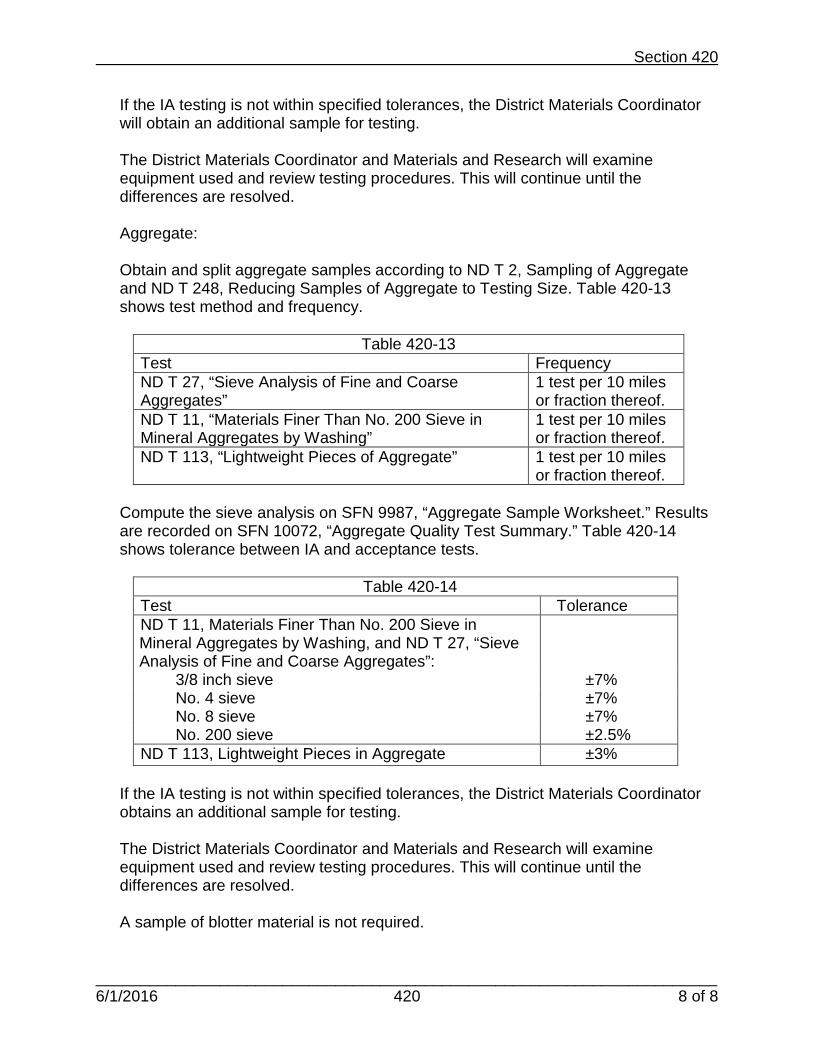
Section 420
______________________________________________________________________6/1/2016 420 8 of 8
If the IA testing is not within specified tolerances, the District Materials Coordinator will obtain an additional sample for testing.
The District Materials Coordinator and Materials and Research will examine equipment used and review testing procedures. This will continue until the differences are resolved.
Aggregate:
Obtain and split aggregate samples according to ND T 2, Sampling of Aggregate and ND T 248, Reducing Samples of Aggregate to Testing Size. Table 420-13 shows test method and frequency.
Table 420-13
Test Frequency ND T 27, “Sieve Analysis of Fine and Coarse Aggregates”
1 test per 10 miles or fraction thereof.
ND T 11, “Materials Finer Than No. 200 Sieve in Mineral Aggregates by Washing”
1 test per 10 miles or fraction thereof.
ND T 113, “Lightweight Pieces of Aggregate” 1 test per 10 miles or fraction thereof.
Compute the sieve analysis on SFN 9987, “Aggregate Sample Worksheet.” Results are recorded on SFN 10072, “Aggregate Quality Test Summary.” Table 420-14 shows tolerance between IA and acceptance tests.
Table 420-14
Test Tolerance ND T 11, Materials Finer Than No. 200 Sieve in Mineral Aggregates by Washing, and ND T 27, “Sieve Analysis of Fine and Coarse Aggregates”:
3/8 inch sieve ±7% No. 4 sieve ±7% No. 8 sieve ±7% No. 200 sieve ±2.5% ND T 113, Lightweight Pieces in Aggregate ±3%
If the IA testing is not within specified tolerances, the District Materials Coordinator obtains an additional sample for testing.
The District Materials Coordinator and Materials and Research will examine equipment used and review testing procedures. This will continue until the differences are resolved.
A sample of blotter material is not required.

Section 421
______________________________________________________________________3/13/2019 Revised 421 Page 1 of 3
Section 421 Micro Surfacing
421.01 Description. This work consists of applying a thin overlay material of modified emulsified asphalt, aggregate, water and additives over a prepared surface. 421.02 Acceptance Sampling and Testing During Stockpiling. Engineer Responsibility.
Obtain and split aggregate samples according to ND T 2, “Sampling of Aggregate,” and ND T 248, “Reducing Samples of Aggregate to Testing Size.” Obtain five independent samples from the stockpile. Each sample is tested separately. Table 421-1 shows test methods to be conducted and frequency of testing.
Table 421-1
Tests Frequency ND T 27, “Sieve Analysis of Fine and Coarse Aggregates”
Minimum of one per project
ND T 11, “Materials Finer Than No. 200 Sieve in Mineral Aggregates by Washing”
Minimum of one per project
ND T 176, “Plastic Fines in Graded Aggregates and Soils by Use of Sand Equivalent Test”
Minimum of one per project
Compute the sieve analysis results on SFN 9987, “Aggregate Sample Worksheet” and sand equivalent on SFN 51730, “Sand Equivalent of Fine Aggregate.”
421.03 Acceptance Sampling and Testing During Mix Production. A. Engineer Responsibility.
Obtain material for determining moisture content.
Table 421-2 shows test methods to be conducted and frequency of testing.
Table 421-2 Test Frequency ND T 255, “Total Evaporable Moisture Content of Aggregate by Drying”
3 test results per day.

Section 421
______________________________________________________________________3/13/2019 Revised 421 Page 2 of 3
Bitumen shall be sampled by the Contractor under the observation of the Engineer. Two samples of bitumen shall be obtained from each load delivered to the project. The Engineer shall take possession of both samples. Ensure material is sampled according to NDDOT 1, “Sampling of Bituminous Materials.” Table 421-3 shows test methods to be conducted and frequency of testing.
Submit samples to Materials and Research for testing.
B. Materials and Research Division Responsibility.
Bitumen:
Materials and Research tests the random sample from both halves of the project. If the samples pass, the entire project is accepted with no further testing.
If one sample passes from either half of the project then that half is accepted with no further testing.
If one sample fails, then all samples from that half of the project are submitted to Materials and Research for testing.
Materials and Research will inform the District when sample submittal is required due to failing tests.
Materials and Research will then test samples around the one that does not pass to determine a failing lot size. For example, using Table 421-3 there are four loads of emulsion delivered during the first half of a project and five loads for the second half of the project.
Table 421-3 First Half of Project
Sample 1 Sample 2 Sample 3 Sample 4 Second Half of Project
Sample 5 Sample 6 Sample 7 Sample 8 Sample 9
The District submits Sample 3 and Sample 7. If Sample 3 from the first half passes, all material from the first half is accepted with no further testing. If Sample 7 from the second half fails, Materials and Research will test Samples 6 and 8. If Sample 6 passes, Sample 5 is accepted with no further testing. If Sample 8 fails, Sample 9 is tested. If Sample 9 passes, the failing lot size is made up of loads 7 and 8.

Section 421
______________________________________________________________________3/13/2019 Revised 421 Page 3 of 3
421.04 Independent Assurance (IA) Samples and Tests. District Materials Coordinators Responsibility.
Obtain and split aggregate samples according to ND T 2, “Sampling of Aggregate,” and ND T 248, “Reducing Samples of Aggregate to Testing Size.” This sample shall be an equal split from the engineer’s five stockpile acceptance samples. Table 421-4 shows test methods to be conducted and frequency of testing.
Table 421-4
Tests Frequency ND T 27, “Sieve Analysis of Fine and Coarse Aggregates”
Minimum of one per project
ND T 11, “Materials Finer Than No. 200 Sieve in Mineral Aggregates by Washing”
Minimum of one per project
ND T 176, “Plastic Fines in Graded Aggregates and Soils by Use of Sand Equivalent Test”
Minimum of one per project
Compute the sieve analysis results on SFN 9987, “Aggregate Sample Worksheet” and sand equivalent on SFN 51730, “Sand Equivalent of Fine Aggregate.”
Table 421-5 shows the tolerance requirements between IA and acceptance tests.
Table 421-5
Tests Tolerance ND T 11, “Materials Finer than No. 200 Sieve in Mineral Aggregates by Washing,” ND T 27, “Sieve Analysis of Fine and Coarse Aggregates”:
• 3/8” sieve ±7% • #4 sieve ±7% • #8 - #100 sieves ±7% • #200 sieve ±2.5%
ND T 176, “Fines in Graded Aggregates and Soils by Use of Sand Equivalent Test”
±5%
If the IA testing is not within specified tolerances, the District Materials Coordinator will obtain an additional sample for testing.
The District Materials Coordinator and Materials and Research will examine equipment used and review testing procedures until the differences are resolved.

Intentionally Left Blank
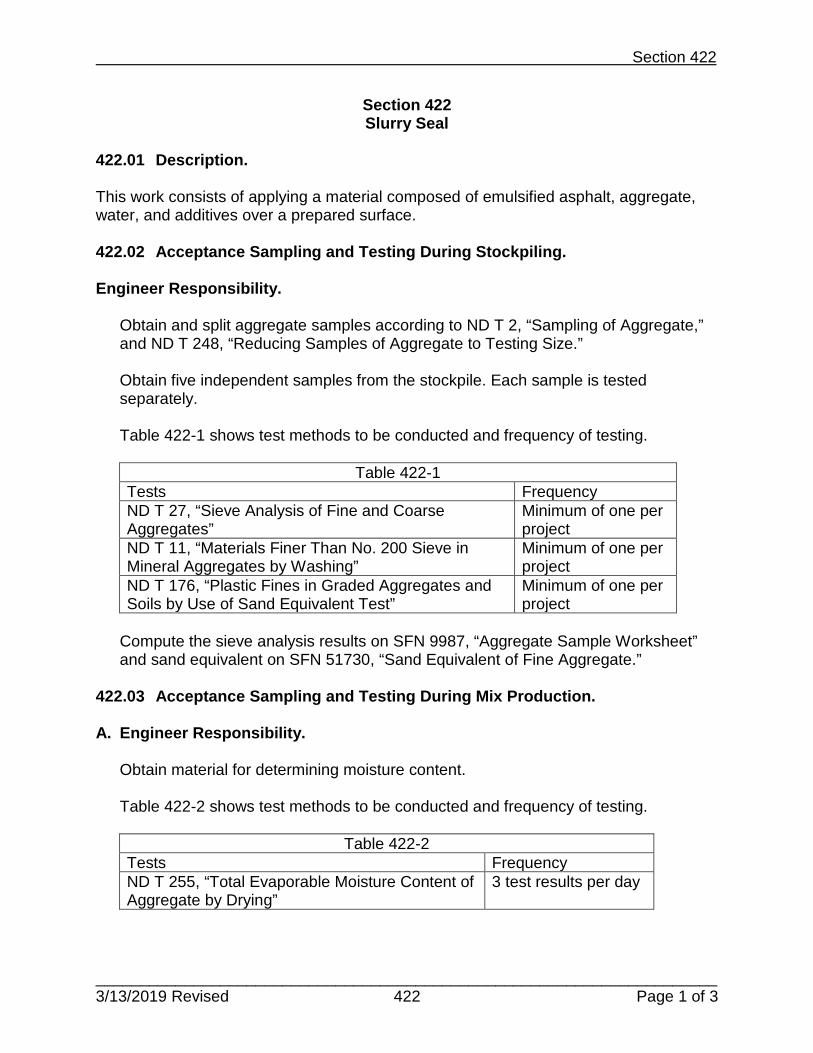
Section 422
______________________________________________________________________3/13/2019 Revised 422 Page 1 of 3
Section 422 Slurry Seal
422.01 Description. This work consists of applying a material composed of emulsified asphalt, aggregate, water, and additives over a prepared surface. 422.02 Acceptance Sampling and Testing During Stockpiling. Engineer Responsibility.
Obtain and split aggregate samples according to ND T 2, “Sampling of Aggregate,” and ND T 248, “Reducing Samples of Aggregate to Testing Size.”
Obtain five independent samples from the stockpile. Each sample is tested separately. Table 422-1 shows test methods to be conducted and frequency of testing.
Table 422-1
Tests Frequency ND T 27, “Sieve Analysis of Fine and Coarse Aggregates”
Minimum of one per project
ND T 11, “Materials Finer Than No. 200 Sieve in Mineral Aggregates by Washing”
Minimum of one per project
ND T 176, “Plastic Fines in Graded Aggregates and Soils by Use of Sand Equivalent Test”
Minimum of one per project
Compute the sieve analysis results on SFN 9987, “Aggregate Sample Worksheet” and sand equivalent on SFN 51730, “Sand Equivalent of Fine Aggregate.”
422.03 Acceptance Sampling and Testing During Mix Production. A. Engineer Responsibility.
Obtain material for determining moisture content.
Table 422-2 shows test methods to be conducted and frequency of testing.
Table 422-2 Tests Frequency ND T 255, “Total Evaporable Moisture Content of Aggregate by Drying”
3 test results per day

Section 422
______________________________________________________________________3/13/2019 Revised 422 Page 2 of 3
Bitumen shall be sampled by the Contractor under the observation of the Engineer. Two samples of bitumen shall be obtained from each load delivered to the project. The Engineer shall take possession of both samples. Ensure material is sampled according to NDDOT 1, “Sampling of Bituminous Materials.” Table 422-3 shows test methods to be conducted and frequency of testing.
Submit samples to Materials and Research for testing.
B. Materials and Research Division Responsibility.
Bitumen:
Materials and Research tests the random sample from both halves of the project. If the samples pass, the entire project is accepted with no further testing.
If one sample passes from either half of the project then that half is accepted with no further testing.
If one sample fails, then all samples from that half of the project are submitted to Materials and Research for testing.
Materials and Research will inform the District when sample submittal is required due to failing tests.
Materials and Research will then test samples around the one that does not pass to determine a failing lot size. For example, using Table 422-3 there are four loads of emulsion delivered during the first half of a project and five loads for the second half of the project.
Table 422-3 First Half of Project
Sample 1 Sample 2 Sample 3 Sample 4 Second Half of Project
Sample 5 Sample 6 Sample 7 Sample 8 Sample 9
The District submits Sample 3 and Sample 7. If Sample 3 from the first half passes, all material from the first half is accepted with no further testing.
If Sample 7 from the second half fails, Materials and Research will test Samples 6 and 8. If Sample 6 passes, Sample 5 is accepted with no further testing.
If Sample 8 fails, Sample 9 is tested. If Sample 9 passes, the failing lot size is made up of loads 7 and 8.

Section 422
______________________________________________________________________3/13/2019 Revised 422 Page 3 of 3
422.04 Independent Assurance (IA) Samples and Tests. District Materials Coordinators Responsibility.
Obtain and split aggregate samples according to ND T 2, “Sampling of Aggregate,” and ND T 248, “Reducing Samples of Aggregate to Testing Size.” This sample shall be an equal split from the Engineer’s five stockpile acceptance samples. Table 422-4 shows test methods to be conducted and frequency of testing.
Table 422-4
Tests Worksheet ND T 27, “Sieve Analysis of Fine and Coarse Aggregates”
Minimum of one per project
ND T 11, “Materials Finer Than No. 200 Sieve in Mineral Aggregates by Washing”
Minimum of one per project
ND T 176, “Plastic Fines in Graded Aggregates and Soils by Use of Sand Equivalent Test”
Minimum of one per project
Compute the sieve analysis results on SFN 9987, “Aggregate Sample Worksheet” and sand equivalent on SFN 51730, “Sand Equivalent of Fine Aggregate.”
Table 422-5 shows tolerance requirements between IA and acceptance tests.
Table 422-5
Tests Tolerance ND T 11, “Materials Finer than No. 200 Sieve in Mineral Aggregates by Washing,” and ND T 27, “Sieve Analysis of Fine and Coarse Aggregates”:
• 3/8” sieve ±7% • #4 sieve ±7% • #8 - #100 sieves ±7% • #200 sieve ±2.5%
ND T 176, “Fines in Graded Aggregates and Soils by Use of Sand Equivalent Test”
±5%
If the IA testing is not within specified tolerances, the District Materials Coordinator will obtain an additional sample for testing.
The District Materials Coordinator and Materials and Research will examine equipment used and review testing procedures until the differences are resolved.

Intentionally Left Blank

Section 430
___________________________________________________________________ 3/13/2019 Revised 430 Page 1 of 17
Section 430
Hot Mix Asphalt (HMA) Sampling and Testing Requirements 430.01 Description. This work consists of constructing one or more courses of bituminous pavement on a prepared surface. This section includes:
• Contractor Quality Control (QC) testing for pavements. • Department’s responsibilities for Quality Assurance (QA) testing. • Independent Assurance (IA) testing. • Dispute resolution requirements.
QC tests that have been verified by QA tests will be used for the acceptance of materials. 430.02 Quality Control Testing. The Contractor's QC program will be conducted by certified personnel as outlined in the NDDOT Technical Certification Program. QC samples will be split under the observation of the Engineer. A. Testing During Aggregate Production.
1. Engineer Responsibility.
Reserved.
2. Contractor Responsibility. The Contractor will obtain and reduce aggregate samples according to ND T 2, “Sampling of Aggregates,” and ND T 248, “Reducing Samples of Aggregate to Testing Size.” a. The Contractor will perform one test per 1,000 tons of material produced for each
aggregate stockpile.
Table 430-1 lists the tests to be conducted.

Section 430
___________________________________________________________________ 3/13/2019 Revised 430 Page 2 of 17
Table 430-1 Tests Worksheet ND T 27, “Sieve Analysis of Fine and Coarse Aggregates”
SFN 9987, Aggregate Sample Worksheet
ND T 11, “Materials Finer Than No. 200 Sieve in Mineral Aggregates by Washing”
SFN 9987, Aggregate Sample Worksheet
b. The Contractor will test one sample from the first 5,000 tons of material
produced from each stockpile. After the initial testing, the testing frequency will change to one sample tested for each 10,000 tons of material produced per stockpile.
Table 430-2 lists the tests to be conducted.
Table 430-2 Tests Worksheet NDDOT 4, “Percentage of Fracture Particles in Coarse Aggregate”
SFN 9987, Aggregate Sample Worksheet
ND T 113, “Lightweight Pieces in Aggregate” SFN 9987, Aggregate Sample Worksheet
ND T 304, “Fine Aggregate Angularity” SFN 51701, Uncom- pacted Void Content of Fine Aggregate
ND T 176, “Plastic Fines in Graded Aggregates and Soils by Use of the Sand Equivalent Test”
SFN 51730, Sand Equivalent of Fine Aggregate
ND D 4791, “Test Method for Flat Particles, Elongated Particles, or Flat and Elongated Particles in Coarse Aggregate”
SFN 51700, Flat or Elongated Particles in Coarse Aggregate
c. For each stockpile the Contractor will obtain a 90-pound sample for every 10,000
tons of material produced. The Contractor will split the sample and give one half of the sample to the Engineer. The sample will be obtained and split under the observation of the Engineer.
d. When a stockpile is less than 10,000 tons for the project, a minimum of two
samples per stockpile will be obtained and tests performed. Table 430-3 lists the tests to be conducted.

Section 430
___________________________________________________________________ 3/13/2019 Revised 430 Page 3 of 17
Table 430-3 Tests Worksheet ND T 84, “Specific Gravity and Absorption of Fine Aggregate”
SFN 2199, Fine Aggregate Specific Gravity Worksheet
ND T 85, “Specific Gravity and Absorption of Coarse Aggregate”
SFN 10081, Coarse Aggregate Specific Gravity Worksheet
3. District Materials Coordinator Responsibility.
This section is to determine the specific gravity of the material according to Section 430.04 C.2, “Determination of Specific Gravity” in the NDDOT Standard Specifications for Road and Bridge Construction. The District Materials Coordinator will obtain a split of the sample from the Contractor and determine the bulk (dry), apparent specific gravity, and the percent water absorption of each stockpile according to Table 430-3. The District Materials Coordinator will conduct the tests on the initial sample received. The District Materials Coordinator has the option to run tests of any additional samples that are received.
B. Mix Design Requirements.
1. Engineer Responsibility. Reserved.
2. Contractor Responsibility.
After the specific gravity of the material has been determined as specified in Section 430.04 C.2, “Determination of Specific Gravity,” NDDOT Standard Specifications for Road and Bridge Construction, the Contractor will develop a mix design. The mix design will meet all of the requirements as specified in Section 430.03 C, “Superpave Mix Properties,” NDDOT Standard Specifications for Road and Bridge Construction. The Contractor will use the Department’s mix design program available at www.dot.nd.gov. The Contractor will submit the completed mix design, including all test data, to the Engineer as specified in Section 430.04 D, “Mix Design,” of the NDDOT Standard Specifications for Road and Bridge Construction.

Section 430
___________________________________________________________________ 3/13/2019 Revised 430 Page 4 of 17
3. District Materials Coordinator Responsibility. The District Materials Coordinator will verify the Contractor mix design by using one or more of the following procedures: a. A full mix design using the materials and mix proportions supplied by the
Contractor. b. A one-point mix design using the Contractor’s optimum asphalt content, the
materials, and mix proportions supplied by the Contractor. c. NDDOT produced specimen developed from loose asphaltic concrete mix
prepared at the optimum asphalt content recommended by the Contractor mix design.
d. Historic data from past projects utilizing the same aggregate source.
The mix design will be approved if the testing is within the tolerances shown in Table 430-4.
Table 430-4 Tests Tolerance ND T 27, “Sieve Analysis of Fine and Coarse Aggregates,” and ND T 11, “Materials Finer Than No. 200 Sieve in Mineral Aggregates by Washing”:
• No. 4 sieve and larger ±5 • No. 30 sieve ±3 • No. 200 sieve ±1.5
NDDOT 4, “Percentage of Fracture Particles in Coarse Aggregate” ±5 ND T 113, “Lightweight Pieces in Aggregate” ±1.0
ND T 304, “Fine Aggregate Angularity” ±1 ND T 176, “Plastic Fines in Graded Aggregates and Soils By Use of the Sand Equivalent Test” ±5 ND D 4791, “Test Method for Flat Particles, Elongated Particles, or Flat and Elongated Particles in Coarse Aggregate” ±1 Aggregate Bulk Specific Gravity (dry), each fraction. ±0.040 Aggregate Apparent Specific Gravity, each fraction. ±0.040 Air Voids - ND T 209, “Theoretical Maximum Specific Gravity and Density of Hot Mix Asphalt,” and ND T 166, “Bulk Specific Gravity of Compacted Hot Mix Asphalt Using Saturated Surface Dry Specimens” ±1.0 ND T 209, “Theoretical Maximum Specific Gravity and Density of Hot Mix Asphalt” ±0.030

Section 430
___________________________________________________________________ 3/13/2019 Revised 430 Page 5 of 17
If the Contractor’s mix design is not approved, the Contractor will submit another mix design. An approved mix design is required before beginning production of hot bituminous pavement.
4. Materials and Research Division Responsibility. Reserved.
C. Testing During Mix Production.
1. Engineer Responsibility.
During mix production, one half of the aggregate and hot mix asphalt QC samples will be retained by the QA. These samples will be retained until QA testing confirms the validity of the QC testing.
2. Contractor Responsibility.
a. The Contractor will perform ND T 255, “Total Evaporable Moisture Content of Aggregate by Drying,” twice on the first day of mix production and once per day before plant startup of mix production thereafter. The Contractor will perform additional testing after a rain event until the test results are consistent.
b. The Contractor will obtain an aggregate sample from the cold feed belt according to ND T 2, “Sampling of Aggregates,” at times directed by the Engineer. The Contractor will obtain one sample for each 1,500 tons of material produced, with a minimum of one sample obtained per day, as directed by the Engineer. The Contractor will split the sample, under the observation of the Engineer, according to ND T 248, “Reducing Samples of Aggregate to Testing Size,” and will bag and number the samples. The Contractor will perform testing on one half of the sample and will submit the remaining half to the Engineer. Table 430-5 lists the tests to be conducted.

Section 430
___________________________________________________________________ 3/13/2019 Revised 430 Page 6 of 17
Table 430-5 Tests Worksheet ND T 27, “Sieve Analysis of Fine and Coarse Aggregates”
SFN 9987, Aggregate Sample Worksheet
ND T 11, “Materials Finer Than No. 200 Sieve in Mineral Aggregates by Washing”
SFN 9987, Aggregate Sample Worksheet
*ND T 304, “Fine Aggregate Angularity” SFN 51701, Uncom- pacted Void Content of Fine Aggregate
*One sample for each 3000 tons of material produced with a minimum of one sample per day. c. The Contractor will obtain three random aggregate samples from the cold feed
belt for each lot of 10,000 tons of mix produced. The Contractor will test each sample and the Engineer will determine acceptance of the lot based on the average of the three samples.
If the results of each sample from a lot are within the designated range, the Contractor will collect three samples from the next lot and test one of the samples. If the results of the test are within the designated range, the Engineer will accept the lot. If the results of the test are outside of the designated range, the Contractor will test the remaining two samples and the Engineer will determine acceptance of the lot based on the average of the three test results. When the average of three results is needed to determine acceptance of a lot, the Contractor will continue to test three samples for each lot of 10,000 tons of material. The Contractor may return to testing a single sample only after all three samples are within the designated range.
Table 430-6 lists the tests to be conducted.
Table 430-6 Tests Worksheet NDDOT 4, “Percentage of Fracture Particles in Coarse Aggregate”
SFN 9987, Aggregate Sample Worksheet
ND T 113, “Lightweight Pieces in Aggregate” SFN 9987, Aggregate Sample Worksheet
*ND T 176, “Plastic Fines in Graded Aggregates and Soils by Use of the Sand Equivalent Test”
SFN 51730, Sand Equivalent of Fine Aggregate
ND D 4791, “Test Method for Flat Particles, Elongated Particles, or Flat and Elongated Particles in Coarse Aggregate”
SFN 51700, Flat or Elongated Particles in Coarse Aggregate
*The test results are not averaged.

Section 430
___________________________________________________________________ 3/13/2019 Revised 430 Page 7 of 17
d. The Contractor will obtain a mix sample each time an aggregate sample is taken for sieve analysis. The sample is obtained according to NDDOT 5, “Sampling and Splitting Field Verification Hot Mix Asphalt (HMA) Samples.”
Table 430-7 lists the tests to be conducted.
Table 430-7 Tests Worksheet ND T 312, “Preparing and Determining the Density of Hot Mix Asphalt Specimens by Means of Superpave Gyratory Compactor”
SFN 50289, Maximum Density Worksheet
ND T 166, “Bulk Specific Gravity of Compacted Hot Mix Asphalt Using Saturated Surface-Dry Specimens”
SFN 50289, Maximum Density Worksheet
ND T 209, “Theoretical Maximum Specific Gravity and Density of Hot Mix Asphalt”
SFN 50289, Maximum Density Worksheet
e. Contractor will collect bituminous samples, under the observation of the Engineer, according to NDDOT 1, “Sampling of Bituminous Materials.”
Obtain one sample for every 250 tons of material for each supplier and grade of asphalt cement, or fraction thereof, randomly selected and observed by the Engineer.
3. District Materials Coordinator Responsibility.
If the project is on the NHS system the District Materials Coordinator will complete SFN 13889, Project Records Samples/Tests Report, and send a copy to the engineer at project completion. The Contractor will be required to obtain one core per mile of roadway paved at random locations selected by the District Materials Coordinator after the final HMA lift is placed. The Engineer will take width measurements at the same location that the cores are obtained.
4. Materials and Research Division Responsibility.
Tests will be run for acceptance or IA according to AASHTO M 320, “Performance-Graded Asphalt Binder.”

Section 430
___________________________________________________________________ 3/13/2019 Revised 430 Page 8 of 17
430.03 Quality Assurance Testing A. General.
Quality assurance testing will be performed during mix production.
B. Contractor Responsibility.
The Contractor will collect samples under the observation of the Engineer for bitumen and coring as required.
C. Engineer Responsibility.
1. Aggregate and Mix Testing.
The Engineer will conduct QA tests on samples collected separately from the Contractor’s sample. Aggregate samples collected at the plant, and asphalt mix samples collected at the paver will be obtained by the Contractor under the observation of the Engineer.
Aggregate samples from the cold feed belt are obtained according to ND T 2, “Sampling of Aggregates.” Asphalt mix samples are obtained according to NDDOT 5, “Procedure for Sampling and Splitting Field Verification HBP Samples.” a. The Engineer will conduct tests a minimum of four times during the Contractor’s
first 15,000 tons of mix production, and will conduct a minimum of one set of tests per production day. After the first 15,000 tons of mix has been produced, the Engineer will perform these tests at least once per day of mix production.
Table 430-8 lists the tests to be conducted.

Section 430
___________________________________________________________________ 3/13/2019 Revised 430 Page 9 of 17
Table 430-8 Tests Worksheet ND T 27, “Sieve Analysis of Fine and Coarse Aggregates”
SFN 9987, Aggregate Sample Worksheet
ND T 11, “Materials Finer than No. 200 Sieve in Mineral Aggregates by Washing”
SFN 9987, Aggregate Sample Worksheet
ND T 304, “Fine Aggregate Angularity” SFN 51701, Uncom- pacted Void Content of Fine Aggregate
ND T 312, “Preparing and Determining the Density of Hot Mix Asphalt Specimens by Means of Superpave Gyratory Compactor”
SFN 50289, Maximum Density Worksheet
ND T 209, “Theoretical Maximum Specific Gravity and Density of Hot Mix Asphalt”
SFN 50289, Maximum Density Worksheet
ND T 166, “Bulk Specific Gravity of Compacted Hot Mix Asphalt Using Saturated Surface-Dry Specimens”
SFN 50289, Maximum Density Worksheet
b. The Contractor and Engineer will compare the results from one QC test to the
QA test. Table 430-9 shows the allowable tolerance range for each test.
Table 430-9
Tests Tolerance ND T 27, “Sieve Analysis of Fine and Coarse Aggregates” and ND T 11, “Materials Finer Than No. 200 Sieve in Mineral Aggregates by Washing”:
• No. 4 sieve and larger ±7 • No. 30 sieve ±5 • No. 200 sieve ±2.5
ND T 304, “Fine Aggregate Angularity” ±1
Air Voids - ND T 209, “Theoretical Maximum Specific Gravity and Density of Hot Mix Asphalt”; and ND T 166, “Bulk Specific Gravity of Compacted Hot Mix Asphalt Using Saturated Surface Dry Specimens”
±1.0
ND T 166 “Bulk Specific Gravity of Compacted Hot Mix Asphalt Using Saturated Surface-Dry Specimens”
±0.040
ND T 209, “Theoretical Maximum Specific Gravity and Density of Hot Mix Asphalt (Max Specific Gravity)”
±0.035

Section 430
___________________________________________________________________ 3/13/2019 Revised 430 Page 10 of 17
If the comparison for a test listed in Table 430-9 leads to a result outside the ranges specified, the Engineer will request an additional test. A three-way split sample will be tested between the QC, QA, and District Materials Coordinator. Evaluation of the procedures and equipment will be conducted to determine the cause of the discrepancy. If the discrepancy cannot be rectified, the dispute resolution procedure in Section 430.04 of this document will be followed.
c. The Engineer will conduct one test for the first 10,000 tons of mix production and
one test every 30,000 tons thereafter. Table 430-10 lists the tests to be conducted.
Table 430-10
Tests Worksheet NDDOT 4, “Percentage of Fracture Particles in Coarse Aggregate”
SFN 9987, Aggregate Sample Worksheet
ND T 113, “Lightweight Pieces in Aggregate” SFN 9987, Aggregate Sample Worksheet
ND T 176, “Plastic Fines in Graded Aggregates and Soils by Use of the Sand Equivalent Test”
SFN 51730, Sand Equivalent of Fine Aggregate
ND D 4791, “Test Method for Flat Particles, Elongated Particles, or Flat and Elongated Particles in Coarse Aggregate”
SFN 51700, Flat or Elongated Particles in Coarse Aggregate
d. The Contractor and Engineer will compare the results of the QC and QA tests.
Table 430-11 shows the allowable tolerance range for each test.
Table 430-11 Tests Tolerance NDDOT 4, “Percentage of Fracture Particles in Coarse Aggregate”
±5
ND T 113, “Lightweight Pieces in Aggregate” ±3.0 ND T 176, “Plastic Fines in Graded Aggregates and Soils by Use of the Sand Equivalent Test”
±7
ND D 4791, “Test Method for Flat Particles, Elongated Particles, or Flat and Elongated Particles in Coarse Aggregate”
±3
If the test result comparisons are within the tolerances of Table 430-11 and the QC results are within specifications, than the samples in the Engineer’s possession for that lot are to be discarded.

Section 430
___________________________________________________________________ 3/13/2019 Revised 430 Page 11 of 17
If the comparison for a test listed in Table 430-11 leads to a result outside the ranges specified, the Engineer will request an additional test. A three-way split sample will be tested between the QC, QA, and District Materials Coordinator. Evaluation of the procedures and equipment will be conducted to determine the cause of the discrepancy. If the discrepancy cannot be rectified, the dispute resolution procedure in Section 430.04 of this document will be followed. If the retest also leads to a result outside the specified range, the Contractor will cease production and take corrective action. If the discrepancy cannot be rectified, the dispute resolution procedure in Section 430.04 of this document will be followed. Tests performed by the District Materials Coordinator will not be used for material acceptance.
2. In-Place Density Testing.
The Engineer will divide the pavement into lots. A lot is equal to the amount of material, in tons, placed each production day. If a shoulder, or part of a shoulder, is placed monolithically with the mainline, the shoulder quantity will be excluded from the quantity of material represented by the lot. A sublot is defined as a single lift, one paver width wide and 2,000 feet long. If a partial sublot is less than 1,000 feet, it will be included in the previous sublot. A partial sublot, greater than 1,000 feet in length will be considered a separate sublot. The Engineer will direct the Contractor to obtain two cores from each sublot. The station and offset location of each core will be determined using random numbers. If the location of the core falls within one foot of the edge of the pavement, the Engineer will adjust the location or generate new random numbers to select a different area. The Engineer will record the information on SFN 10071, “Compaction Control” and will observe the coring procedure. The Engineer will take immediate possession of the cores. The Engineer will determine the density of the cores in accordance with ND T 166, “Bulk Specific Gravity of Compacted Hot Mix Asphalt Using Saturated Surface-Dry Specimens,” and ND T 209, “Maximum Theoretical Density.” The Engineer will determine the acceptance of the sublot based on the average of the two cores. The average of the two cores is recorded on SFN 59132, Density Pay Factor.

Section 430
___________________________________________________________________ 3/13/2019 Revised 430 Page 12 of 17
The density of a lot will be determined using the recorded average densities of the sublots contained within the lot. The recorded average densities of the sublots will be totaled and divided by the number of sublots within the lot to obtain the average density of the pavement.
3. Bitumen Testing. Bituminous samples are obtained for testing according to NDDOT 1.
D. District Materials Coordinator Responsibility.
Reserved.
E. Materials and Research Division Responsibility.
Materials and Research will perform one test on a composite aggregate sample obtained during the beginning of aggregate stockpiling according to Table 430-12.
Table 430-12
Test Worksheet AASHTO T 96, “Standard Method of Test for Resistance to Degradation of Small-Size Coarse Aggregate by Abrasion and Impact in the Los Angeles Machine”
SFN 9987, Aggregate Sample Worksheet
If the aggregate source has been tested previously by the Department and the material is within allowable limits, the L.A. Abrasion test may be waived at the discretion of the District Materials Coordinator.
Bituminous samples are obtained and tested according to NDDOT 1.
430.04 Dispute Resolution If the cause of disagreement between the QC and QA results cannot be determined, a dispute resolution process will be implemented. The material remaining from retained samples will be sent to the Materials and Research Division. Materials and Research will test the material. The test results from Materials and Research will be considered final.

Section 430
___________________________________________________________________ 3/13/2019 Revised 430 Page 13 of 17
430.05 Independent Assurance (IA) Testing A. General
IA testing will occur during mix production of aggregate and mix. IA samples are a split sample tested by the Contractor, the Engineer, and the District Materials Coordinator.
Table 430-13 lists the tests to be conducted.
Table 430-13
Tests Worksheet ND T 27, “Sieve Analysis of Fine and Coarse Aggregates”
SFN 9987, Aggregate Sample Worksheet
ND T 11, “Materials Finer Than No. 200 Sieve in Mineral Aggregates by Washing”
SFN 9987, Aggregate Sample Worksheet
NDDOT 4, “Percentage of Fracture Particles in Coarse Aggregate”
SFN 9987, Aggregate Sample Worksheet
ND T 113, “Lightweight Pieces in Aggregate” SFN 9987, Aggregate Sample Worksheet
ND T 304, “Fine Aggregate Angularity” SFN 51701, Uncom- pacted Void Content of Fine Aggregate
ND T 176, “Plastic Fines in Graded Aggregates and Soils by Use of the Sand Equivalent Test”
SFN 51730, Sand Equivalent of Fine Aggregate
ND D 4791, “Test Method for Flat Particles, Elongated Particles, or Flat and Elongated Particles in Coarse Aggregate”
SFN 51700, Flat or Elongated Particles in Coarse Aggregate
ND T 312, “Preparing and Determining the Density of Hot Mix Asphalt Specimens by Means of Superpave Gyratory Compactor”
SFN 50289, Maximum Density Worksheet
ND T 209, “Theoretical Maximum Specific Gravity and Density of Hot Mix Asphalt”
SFN 50289, Maximum Density Worksheet
ND T 166, “Bulk Specific Gravity of Compacted Hot Mix Asphalt Using Saturated Surface-Dry Specimens”
SFN 50289, Maximum Density Worksheet
1. Engineer Responsibility.
IA tests run by the Engineer are additional to required QA samples.

Section 430
___________________________________________________________________ 3/13/2019 Revised 430 Page 14 of 17
2. Contractor Responsibility.
The Contractor will collect IA samples of aggregate and HMA under the observation of the District Materials Coordinator. IA tests run by the Contractor can be used for acceptance in lieu of additional QC samples.
3. District Materials Coordinator Responsibility.
The District Materials Coordinator will periodically observe tests performed by the Contractor and the QA tester and ensure that testing personnel are qualified as outlined in the NDDOT Technical Certification Program.
B. Frequency Testing
Frequency for IA testing is listed in Table 430-14.
Table 430-14 Project Tonnage
Number of Tests/Project
Frequency
<10,000 tons One IA test IA sample will be obtained during the first four tests run by the Contractor.
10,000 - 20,000 tons
One IA test IA sample will be obtained at the approximate mid-point of the project.
20,000 - 30,000 tons
Two IA tests One IA sample will be obtained during the first half of the project and again during the second half of the project.
>30,000 tons Three IA tests IA samples will be obtained during the first half, the approximate midpoint, and the second half of the project.
C. Comparison Testing
The results of the Contractor, Engineer, and District Materials Coordinator tests will be compared. The results of any test must be within the ranges specified in Table 430-15 when compared to any other test.

Section 430
___________________________________________________________________ 3/13/2019 Revised 430 Page 15 of 17
Table 430-15 Tests Tolerance ND T 27, “Sieve Analysis of Fine and Coarse Aggregates, and ND T 11, Materials Finer Than No. 200 Sieve in Mineral Aggregates by Washing”:
• No. 4 sieve and larger ±5 • No. 30 sieve ±3 • No. 200 sieve ±1.5
NDDOT T 4, “Percentage of Fracture Particles in Coarse Aggregate” ±5 ND T 113, “Lightweight Pieces in Aggregate” ±1.0 ND T 304, “Fine Aggregate Angularity” ±1 ND T 176, “Plastic Fines in Graded Aggregates and Soils by Use of the Sand Equivalent Test” ±5 ND D 4791, “Test Method for Flat Particles, Elongated Particles, or Flat and Elongated Particles in Coarse Aggregate” ±2 Air Voids - ND T 209, “Theoretical Maximum Specific Gravity and Density of Hot Mix Asphalt”; and ND T 166, “Bulk Specific Gravity of Compacted Hot Mix Asphalt Using Saturated Surface Dry Specimens.” ±1.0
If the IA testing is not within specified tolerances, the Contractor will obtain an additional sample for testing under the observations of the District Materials Coordinator. The Contractor, Engineer, and District Materials Coordinator will conduct equipment checks and review testing procedures. This will continue until the differences are resolved. The IA tester and either the QC or QA tester, whichever is not within the specified tolerances, will perform the additional IA tests.
D. Gyratory Compliance Tests
For gyratory compliance, the IA will be required to obtain one sample during the first four tests run by the Contractor (QC). This sample will be used to ensure the accuracy of the shared gyratory compactor used by the QC and QA testers. The Contractor will obtain a sample of hot mix for testing. This sample will be taken from any available location except behind the paver. The Contractor will split the sample and give half to the District Materials Coordinator.

Section 430
___________________________________________________________________ 3/13/2019 Revised 430 Page 16 of 17
The IA and QC labs will make gyratory plugs and compare the bulk specific gravity (Gmb) of their specimens. The acceptable tolerance between tests will be:
Bulk Specific Gravity of the Mix (Gmb): ± 0.040 The number and frequency of Gyratory Compliance samples will be based on project tonnage as shown in Table 430-16.
Table 430-16 Project Tonnage Frequency <10,000 No Gyratory Compliance >10,000 One Gyratory Compliance
If the initial testing is not within specified tolerances, the Contractor will obtain an additional sample for testing, under the observations of the District Materials Coordinator. The Contractor and District Materials Coordinator will conduct equipment checks, and review testing procedures. If the second sample is not within specified tolerances, a dispute resolution procedure will be implemented in which a third gyratory will be selected and a three-way split of a sample will be tested. The third gyratory can be from another district or the Materials and Research Division.
430.06 Material and Research Division Program Oversight
The District Materials Coordinator will obtain and equally split this sample. The first half of the sample will be retained and tested by the District Materials Coordinator. The second half of the sample along with test results will be submitted to Materials and Research. Table 430-17 shows test method required and frequency of samples when compared to any other test.
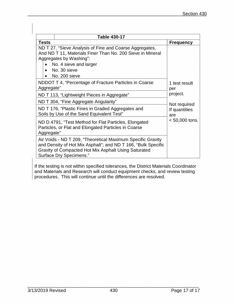
Section 430
___________________________________________________________________ 3/13/2019 Revised 430 Page 17 of 17
Table 430-17 Tests Frequency ND T 27, “Sieve Analysis of Fine and Coarse Aggregates, And ND T 11, Materials Finer Than No. 200 Sieve in Mineral Aggregates by Washing”:
1 test result per project. Not required If quantities are < 50,000 tons.
• No. 4 sieve and larger • No. 30 sieve • No. 200 sieve
NDDOT T 4, “Percentage of Fracture Particles in Coarse Aggregate” ND T 113, “Lightweight Pieces in Aggregate” ND T 304, “Fine Aggregate Angularity” ND T 176, “Plastic Fines in Graded Aggregates and Soils by Use of the Sand Equivalent Test”
ND D 4791, “Test Method for Flat Particles, Elongated Particles, or Flat and Elongated Particles in Coarse Aggregate” Air Voids - ND T 209, “Theoretical Maximum Specific Gravity and Density of Hot Mix Asphalt”; and ND T 166, “Bulk Specific Gravity of Compacted Hot Mix Asphalt Using Saturated Surface Dry Specimens.”
If the testing is not within specified tolerances, the District Materials Coordinator and Materials and Research will conduct equipment checks, and review testing procedures. This will continue until the differences are resolved.

Intentionally Left Blank

APPENDIX 400-A
______________________________________________________________________ 3/13/2019 400-A Page 1 of 1
ACCEPTANCE OF PERFORMANCE GRADED (PG) ASPHALT FOR COUNTY PROJECTS WITH FEDERAL AID
1. General Requirements. The Performance Graded (PG) Asphalt Cement acceptance requirements will apply to all county projects with federal aid.
• PG asphalt can be accepted by certification from any asphalt supplier that meets the
requirements of and is a participating member in the Combined States Binder Group (CSBG).
• For projects with over 20,000 ton of hot mix asphalt, one sample may be randomly
selected for verification testing. PG sample will be obtained according to test procedure NDDOT 1.
• The county shall send the sample to a certified private lab to verify the PG asphalt
cement meets AASHTO M 323. If necessary, a list of certified testing labs can be obtained from the Bituminous Section of the NDDOT Materials and Research Division.
2. Additional Requirements
• The North Dakota Department of Transportation may randomly select asphalt
samples from county projects with federal aid. These samples will be tested, at no cost, to ensure supplier compliance with the CSBG requirements.

Intentionally Left Blank

SECTION 400
FORMS

Intentionally Left Blank


Intentionally Left Blank


FIELD SAMPLING AND TESTING PROGRAM
SECTION 500
RIGID PAVEMENT

Intentionally Left Blank

______________________________________________________________________3/13/2019 Revised 500 1 of 1
SECTION 500 TABLE OF CONTENTS
Section 550 Concrete Pavement 550.01 Description 550.02 Acceptance Samples and Tests 550.03 Independent Assurance (IA) Testing Section 570 Portland Cement Concrete Pavement Repair 570.01 Description 570.02 Acceptance Samples and Tests 570.03 Independent Assurance (IA) Testing Section 575 Dowel Bar Retrofit 575.01 Description 575.02 Acceptance Samples and Tests Reference Forms: SFN 2455 Concrete, Sand, and Gravel Worksheet SFN 7623 Concrete Cylinders SFN 19404 Concrete Core Specimen Worksheet All test procedures used within and referred to in this section can be found under “Testing Procedures” of this manual. Form examples at end of section are for “Reference Only.” Use the most current available forms found on the NDDOT website.

Intentionally Left Blank

Section 550
______________________________________________________________________ 3/13/2019 Revised 550 1 of 7
Section 550 Concrete Pavement
550.01 Description.
This work consists of constructing concrete pavement.
550.02 Acceptance Samples and Tests.
A. Engineer Responsibility.
The Engineer will collect material and conduct testing to verify that the material meets the requirements in Sections 802, 804, 812, and 826 of the NDDOT Standard Specifications for Road and Bridge Construction.
Aggregate:
Aggregate samples will be obtained randomly and split according to ND T 2, “Sampling of Aggregates” and ND T 248, “Reducing Samples of Aggregate to Testing Size.” Table 550-1 shows test method and frequency.
Table 550-1 Test Frequency ND T 27, “Sieve Analysis of Fine and Coarse Aggregates”
1 test result per 5,000 S.Y. rural or 1,500 S.Y. urban of concrete pavement.
ND T 11, “Materials Finer Than No. 200 Sieve in Mineral Aggregates by Washing”
1 test result per 5,000 S.Y. rural or 1,500 S.Y. urban of concrete pavement.
Report results to the District Materials Coordinator on SFN 2455, “Concrete, Sand, and Gravel Worksheet.”
One composite aggregate sample will be submitted to the Materials and Research Division. The sample will be tested for L.A. abrasion and soundness during the beginning of aggregate stockpiling.
Cement:
Submit one random sample of cement per project from the silo, truck, or hopper to the Materials and Research Division. This sample shall be a minimum of 15 lbs. and placed in a moisture proof airtight container so as to avoid absorption of moisture and aeration of the sample.

Section 550
______________________________________________________________________ 3/13/2019 Revised 550 2 of 7
Mix Water:
Obtain one sample per water source according to Section 812 of the NDDOT Standard Specifications for Road and Bridge Construction and submit to the Materials and Research Division.
Concrete:
The Engineer will randomly select locations to conduct testing. Table 550-2 shows test method and frequency.
Table 550-2
Test Frequency ND T 119, “Slump of Hydraulic Cement Concrete” 1 test result per 2,000
S.Y. of concrete pavement.
ND T 152, “Air Content of Freshly Mixed Concrete by Pressure Method”
1 test result per 2,000 S.Y. of concrete pavement.
ND T 121, “Density (Unit Weight), Yield, and Air Content (Gravimetric) of Concrete”
1 test result per 2,000 S.Y. of concrete pavement.
Perform the testing a minimum of one test per day. Opening to Traffic: For determining pavement strength for opening to traffic there are three options. They are as follows:
• Maturity Curve – Verify the maturity curve from the mix design by making cylinders or beams and break near the time that the mix design criteria is met. If the results are within 50 psi flexural or 300 psi compression the curve is valid to use. If the results vary by more than 50 psi flexural or 300 psi compression than a new maturity curve must be developed.
• Cylinders or Beams – Each day make additional cylinders or beams to break to determine strength. The samples must be field cured.
• Cores – Take cores from roadway and break to determine strengths are met for opening to traffic.
Cores:
Obtain cores for thickness and strength. Measure the pavement width at all points
where cores are taken. Submit cores to the Materials and Research Division for testing, along with pertinent information on SFN 19404, “Concrete Core Specimen Worksheet.”
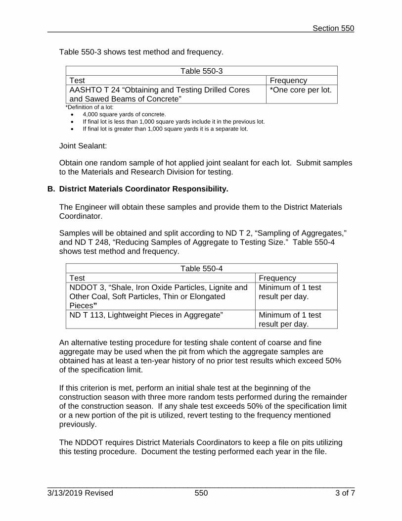
Section 550
______________________________________________________________________ 3/13/2019 Revised 550 3 of 7
Table 550-3 shows test method and frequency.
Table 550-3 Test Frequency AASHTO T 24 “Obtaining and Testing Drilled Cores and Sawed Beams of Concrete”
*One core per lot.
*Definition of a lot: • 4,000 square yards of concrete. • If final lot is less than 1,000 square yards include it in the previous lot. • If final lot is greater than 1,000 square yards it is a separate lot.
Joint Sealant:
Obtain one random sample of hot applied joint sealant for each lot. Submit samples to the Materials and Research Division for testing.
B. District Materials Coordinator Responsibility.
The Engineer will obtain these samples and provide them to the District Materials Coordinator.
Samples will be obtained and split according to ND T 2, “Sampling of Aggregates,” and ND T 248, “Reducing Samples of Aggregate to Testing Size.” Table 550-4 shows test method and frequency.
Table 550-4 Test Frequency NDDOT 3, “Shale, Iron Oxide Particles, Lignite and Other Coal, Soft Particles, Thin or Elongated Pieces”
Minimum of 1 test result per day.
ND T 113, Lightweight Pieces in Aggregate” Minimum of 1 test result per day.
An alternative testing procedure for testing shale content of coarse and fine aggregate may be used when the pit from which the aggregate samples are obtained has at least a ten-year history of no prior test results which exceed 50% of the specification limit. If this criterion is met, perform an initial shale test at the beginning of the construction season with three more random tests performed during the remainder of the construction season. If any shale test exceeds 50% of the specification limit or a new portion of the pit is utilized, revert testing to the frequency mentioned previously.
The NDDOT requires District Materials Coordinators to keep a file on pits utilizing this testing procedure. Document the testing performed each year in the file.

Section 550
______________________________________________________________________ 3/13/2019 Revised 550 4 of 7
C. Materials and Research Division Responsibility.
Aggregate:
The sample will be tested for L.A. abrasion and soundness during the beginning of aggregate stockpiling. Table 550-5 shows test method and frequency.
Table 550-5 Test Frequency AASHTO T 96, “Resistance to Degradation of Small-Size Coarse Aggregate by Abrasion and Impact in the Los Angeles Machine”
*1 test result per project.
AASHTO T 104, “Soundness” (Sodium Sulfate)” *1 test result per project.
*If the aggregate source has been tested previously by the Department and the material is within allowable limits testing will not be required.
Cement:
Test Portland cement according to Section 804 of the NDDOT Standard Specifications for Road and Bridge Construction.
Water:
Test non-potable water according to Section 812 of the NDDOT Standard Specifications for Road and Bridge Construction.
Joint Sealant:
Test joint sealant according to Section 826 of the NDDOT Standard Specifications for Road and Bridge Construction.
Cores:
Test cores submitted from the Engineer.
Table 550-6 shows test method and frequency.
Table 550-6 Test Frequency AASHTO T 22, “Compressive Strength of Cylindrical Concrete Specimens”
1 core per lot.
AASHTO T 148, “Measuring Length of Drilled Concrete Cores”
1 core per lot.
550.03 Independent Assurance (IA) Testing.

Section 550
______________________________________________________________________ 3/13/2019 Revised 550 5 of 7
A. Engineer Responsibility.
Conduct IA tests on split samples taken by the District Materials Coordinator.
Testing performed will be as directed by the District Materials Coordinator. B. District Materials Coordinator Responsibility.
The District Materials Coordinator will obtain these samples and conduct these tests. These samples will be an equal split sample with the Engineer.
Samples will be obtained and split according to ND T 2, “Sampling of Aggregates,”
and ND T 248, “Reducing Samples of Aggregate to Testing Size.” Concrete samples shall be obtained according to ND T 141, “Sampling Freshly Mixed Concrete”.
Table 550-7 shows test and frequency for IA.
Table 550-7 Test Frequency ND T 27, “Sieve Analysis of Fine and Coarse Aggregates”
1 test result per 50,000 S.Y. rural or 15,000 S.Y. urban of concrete pavement.
ND T 11, “Materials Finer Than No. 200 Sieve in Mineral Aggregates by Washing”
1 test result per 50,000 S.Y. rural or 15,000 S.Y. urban of concrete pavement.
ND T 119, “Slump of Hydraulic Cement Concrete”
1 test result per 3 miles rural or 15,000 S.Y. of concrete pavement on urban projects.
ND T 152, “Air Content of Freshly Mixed Concrete by Pressure Method”
1 test result per 3 miles rural or 15,000 S.Y. urban of concrete pavement.
ND T 121, “Density (Unit Weight), Yield, and Air Content (Gravimetric) of Concrete”
1 test result per 3 miles rural or 15,000 S.Y. urban of concrete pavement.

Section 550
______________________________________________________________________ 3/13/2019 Revised 550 6 of 7
The District Materials Coordinator and the Engineer will compare the test results for IA tolerances in Table 550-8.
Table 550-8 Test Tolerance ND T 27, “Sieve Analysis of Fine and Coarse Aggregates,” and ND T 11, “Materials Finer than No. 200 Sieve in Mineral Aggregates by Washing”:
No. 8 sieve and larger ±5 No. 50 sieve ±3 No. 200 sieve ±2
ND T 119, “Slump of Hydraulic Cement Concrete” ±1 inch ND T 152, “Air Content of Freshly Mixed Concrete by Pressure Method” ±1.0% ND T 121, “Density (Unit Weight), Yield, and Air Content (Gravimetric) of Concrete” ±2.5 lb./ft²
C. Materials and Research Division Responsibility.
The District Materials Coordinator will obtain and split this sample. Sample will be submitted to the Materials and Research Division.
Table 550-9 shows frequency for IA testing for physical properties of concrete aggregate.
Table 550-9 Test Frequency NDDOT 3, “Shale, Iron Oxide Particles, Lignite and Other Coal, Soft Particles, Thin or Elongated Pieces”
Minimum of 1 test per project.
ND T 113, “Lightweight Pieces in Aggregate” Minimum of 1 test per project.
The District Materials Coordinator will compare the test results for IA tolerances in Table 550-10.
Table 550-10 Test Tolerance NDDOT 3, “Shale, Iron Oxide Particles, Lignite and Other Coal, Soft Particles, Thin or Elongated Pieces”:
Shale, Iron Oxide Particles, Lignite and Other Coal, and Soft Particles (each) ±1.0 Thin or Elongated Pieces ±2.5

Section 550
______________________________________________________________________ 3/13/2019 Revised 550 7 of 7
If the IA testing is not within specified tolerances, the District Materials Coordinator will obtain an additional sample for testing.
The District Materials Coordinator and Materials and Research personnel will examine equipment used and review testing procedures. This will continue until the differences are resolved.

Intentionally Left Blank

Section 570
3/13/2019 570 Page 1 of 5
Section 570 Portland Cement Concrete Pavement Repair
570.01 Description. This work consists of repairing concrete pavement.
570.02 Acceptance Samples and Tests. A. Engineer Responsibility.
The Engineer will collect material and conduct testing to verify that the material meets the requirements in Section 816 of the NDDOT Standard Specifications for Road and Bridge Construction. Obtain and split samples according to ND T 2, “Sampling of Aggregates” and ND T 248, “Reducing Samples of Aggregate to Testing Size.”
Table 570-1 shows test methods and frequency of testing for aggregate produced.
Table 570-1
Tests Frequency ND T 27, “Sieve Analysis of Fine and Coarse Aggregates”
1 test result every 200 cubic yards of concrete
ND T 11, “Materials Finer Than No. 200 Sieve in Mineral Aggregates by Washing”
1 test result every 200 cubic yards of concrete
ND T 255,”Total Evaporable Moisture Content of Aggregate by Drying”
1 test result on the coarse and fine aggregate daily
Report results to the District Materials Coordinator on SFN 2455, “Concrete, Sand, and Gravel Worksheet.”
Table 570-2 shows test methods and frequency for testing concrete.
Table 570-2
Tests Frequency AASHTO T 119, “Slump of Hydraulic Cement Concrete”
1 test result from the first load each day and one every 75 cubic yards of concrete thereafter
AASHTO T 152, “Air Content of Freshly Mixed Concrete by Pressure Method”
1 test result from the first load each day and one every 75 cubic yards of concrete thereafter
AASHTO T 121, “Density (Unit Weight), Yield, and Air Content (Gravimetric) of Concrete”
1 test result from the first load each day and one every 75 cubic yards of concrete thereafter

Section 570
3/13/2019 570 Page 2 of 5
Perform this testing a minimum of one test per day.
Table 570-3 shows test methods and frequency for casting and testing concrete cylinders.
Table 570-3
Tests Frequency AASHTO T 23, “Making and Curing Concrete Specimens in the Field”
Cast one set of specimens every 250 cubic yards of concrete or a minimum of one set per day.
AASHTO T 22 “Compressive Strength of Cylindrical Concrete Specimens”
*see below
*Opening to Traffic
To determine pavement strength to open to traffic there are three options as follows:
1. Maturity Curve – Verify the maturity curve from the mix design by making
cylinders or beams and break near the time that the mix design criteria is met. If the results are within 50 psi flexural or 300 psi compression, the curve is valid to use. If the results vary by more than 50 psi flexural or 300 psi compression, then a new maturity curve must be developed.
2. Cylinders or Beams – Each day make additional cylinders or beams to break to
determine strength. The samples must be field cured.
3. Cores – Take cores from roadway and break to determine strengths are met for opening to traffic. Record information on SFN 7623, “Concrete Cylinders.”
Mix Water:
Obtain one sample per water source according to Section 812 of the NDDOT Standard Specifications for Road and Bridge Construction and submit to Materials and Research.
B. District Materials Coordinator Responsibility.
The Engineer will obtain these samples and provide them to the District Materials Coordinator.
Obtain and split samples according to ND T 2, “Sampling of Aggregates,” and ND T 248, “Reducing Samples of Aggregate to Testing Size.”

Section 570
3/13/2019 570 Page 3 of 5
Table 570-4 shows test methods and frequency of testing.
Table 570-4
Tests Frequency NDDOT 3, “Shale, Iron Oxide Particles, Lignite and Other Coal, Soft Particles, Thin or Elongated Pieces”
Minimum of 1 test result per project
ND T 113, Lightweight Pieces in Aggregate” Minimum of 1 test result per project
C. Materials and Research Division Responsibility.
Test non-potable water according to Section 812 of the NDDOT Standard Specifications for Road and Bridge Construction.
570.03 Independent Assurance (IA) Testing. A. Engineer Responsibility.
Conduct IA tests on split samples taken by the District Materials Coordinator.
Testing performed will be as directed by the District Materials Coordinator. B. District Materials Coordinator Responsibility.
The District Materials Coordinator will obtain these samples and conduct these tests. These samples will be an equal split sample with the Engineer.
Obtain and split samples according to ND T 2, “Sampling of Aggregates” and ND T 248, “Reducing Samples of Aggregate to Testing Size.”
Table 570-5 shows test methods and frequency for IA testing.
Table 570-5
Tests Frequency ND T 27, “Sieve Analysis of Fine and Coarse Aggregates”
1 test result per project
ND T 11, “Materials Finer Than No. 200 Sieve in Mineral Aggregates by Washing”
1 test result per project

Section 570
3/13/2019 570 Page 4 of 5
In Table 570-6 the District Materials Coordinator and the Engineer will compare the test results for IA tolerances.
Table 570-6
Tests Tolerance ND T 27, “Sieve Analysis of Fine and Coarse Aggregates,” and ND T 11, “Materials Finer than No. 200 Sieve in Mineral Aggregates by Washing:”
• No. 4 sieve and larger • No. 30 sieve • No. 200 sieve
±5 ±3 ±2
If the IA testing is not within specified tolerances, the Engineer will obtain an additional sample for testing under the observation of the District Materials Coordinator.
The Engineer and District Materials Coordinator will examine equipment used and review testing procedures until the differences are resolved.
The District Materials Coordinator will obtain these samples and conduct these tests.
Table 570-7 shows test methods and frequency for testing concrete.
Table 570-7
Tests Frequency AASHTO T 119, “Slump of Hydraulic Cement Concrete” 1 test result per
project. AASHTO T 152, “Air Content of Freshly Mixed Concrete by Pressure Method”
1 test result per project
AASHTO T 121, “Density (Unit Weight), Yield, and Air Content (Gravimetric) of Concrete”
1 test result per project
In Table 570-8 the District Materials Coordinator and the Engineer will compare the test results for IA tolerances.
Table 570-8
Tests Tolerance AASHTO T 119, “Slump of Hydraulic Cement Concrete” ±1 AASHTO T 152, “Air Content of Freshly Mixed Concrete by Pressure Method”
±2
AASHTO T 121, “Density (Unit Weight), Yield, and Air Content (Gravimetric) of Concrete”
±3

Section 570
3/13/2019 570 Page 5 of 5
C. Materials and Research Division Responsibility.
If necessary conduct IA tests on split samples taken by the District Materials Coordinator.
Obtain and split samples according to ND T 2, “Sampling of Aggregates,” and ND T 248, “Reducing Samples of Aggregate to Testing Size.”
Table 570-9 shows test methods and frequency for IA testing.
Table 570-9
Tests Frequency NDDOT 3, “Shale, Iron Oxide Particles, Lignite and Other Coal, Soft Particles, Thin or Elongated Pieces”
Minimum of 1 test result per project
ND T 113, Lightweight Pieces in Aggregate” Minimum of 1 test result per project
The District Materials Coordinator and Materials and Research will compare the test results for IA tolerances in Table 570-10.
Table 570-10
Tests Frequency NDDOT 3, “Shale, Iron Oxide Particles, Lignite and Other Coal, Soft Particles, Thin or Elongated Pieces”
±1.0 ±2.5
ND T 113, Lightweight Pieces in Aggregate” ±2

Intentionally Left Blank

Section 575
____________________________________________________________________________3/13/2019 575 Page 1 of 1
Section 575 Dowel Bar Retrofit
575.01 Description. This work consists of performing a dowel bar retrofit in concrete pavement.
575.02 Acceptance Samples and Tests. Engineer Responsibility.
All sampling and testing requirements can be found in Section 573.03 and 573.04 of the NDDOT Standard Specifications for Road and Bridge Construction.
Cast one set of cylinders for each four hours of production. A set consists of three concrete cylinders for the 4” x 8” size, and two concrete cylinders for the 6” x 12” size. The Engineer can adjust this rate as necessary.

Intentionally Left Blank

SECTION 500
FORMS

Intentionally Left Blank


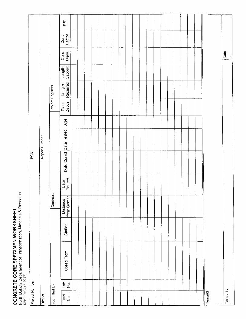
FIELD SAMPLING AND TESTING MANUAL
SECTION 600
STRUCTURES

Intentionally Left Blank

TABLE OF CONTENTS - 600
1
Section 602 CONCRETE STRUCTURES 602.01 DESCRIPTION. 602.02 REQUIRED TESTS AND FREQUENCY.
A. Acceptance Samples and Tests--Field Laboratory Testing B. Independent Assurance Samples and Tests.
1. District Laboratory Testing. 2. Materials and Research Division Testing.
C. Miscellaneous Testing. Section 650 REPAIR AND OVERLAY OF PORTLAND CEMENT CONCRETE BRIDGE
DECKS WITH LOW SLUMP CONCRETE OR LATEX-MODIFIED CONCRETE.
650.01 DESCRIPTION. 650.02 REQUIRED TESTS AND FREQUENCY.
A. Acceptance Samples and Tests--Field Laboratory Testing. B. Independent Assurance Samples and Tests.
1. District Laboratory Testing. 2. Materials and Research Division Testing.

Intentionally Left Blank

602.02 A
Revised 5-99
Section 602
CONCRETE STRUCTURES
602.01 DESCRIPTION.
This work consists of the construction of bridges, cast-in-place box culverts, retaining walls, or portions thereof as shown on the Plans.
602.02 REQUIRED TESTS AND FREQUENCY.
A. Acceptance Samples and Tests--Field Laboratory Testing. Perform one moisture test on the aggregate before the first pour each day (see Section 816.04 of this manual for procedure).
Perform one slump and one air test the first load each day (see Sections 802.03 A and 802.03 B. of this manual for procedure). After the initial load, perform air, slump, and yield tests each time a set of compression test cylinders are cast.
Cast compression test cylinders as indicated in Table 1 (see Section 802.03 E. of this manual for casting procedure). The engineer/manager decides when to cast cylinders. Perform sieve analysis tests as directed by the project engineer/manager with a minimum of two tests per project (see Section 816.04 of this manual for test procedures).
Perform sieve analysis tests (see Section 816.04 of this manual for test procedures) on both the coarse and fine aggregate at the following frequencies: three tests for the first 250 cubic yards (C.Y.) of concrete, two tests for the next 250 C.Y., and one test for each 250 C.Y. thereafter. If aggregate sources change, the testing frequency reverts back to the initial frequency of three tests for the first 250 C.Y. of concrete, two tests for the next 250 C.Y., and one test for each 250 C.Y. thereafter. Perform a minimum of two tests per project. Perform additional sieve analysis tests as directed by the project engineer/manager.
Perform aggregate sampling according to Section 816.01 of this manual.
Submit a minimum of one random sample of cement per project to the Materials and Research Division (see Section 804.02 of this manual for procedure).

602.02 B.1.
Revised 5-99
B. Independent Assurance Samples and Tests.
1. District Laboratory Testing. The District Materials Coordinator or a designated representative must obtain these samples and conduct these tests. Perform Independent assurance tests with equipment other than that used by the project personnel.
Obtain one sieve analysis and physical properties sample of both coarse and fine aggregate for the first 250 C.Y. of concrete and one sample for each 500 C.Y. thereafter (see Sections 816.01 and 816.04 of this manual for procedure). Obtain a minimum of one sample per project.
An alternative testing procedure for testing shale content of coarse and fine aggregate may be used when the pit from which the aggregate samples are obtained has at least a ten-year history of no prior test results which exceed 50% of the specification limit.
If this criteria is met, perform an initial shale test at the beginning of the construction season with three more random tests performed during the remainder of the construction season. If any shale test exceeds 50% of the specification limit or a new portion of the pit is utilized, revert testing to the frequency mentioned previously. The Department requires Materials Coordinators to keep a file on pits utilizing this testing procedure. Document the testing performed each year in the file.
Record the results of air, slump, 28-day cylinder and yield tests on SFN 10069 (see Section 802.03 of this manual for procedure). The frequency for air, slump, and yield tests is one test for every five field tests with a minimum of one test per project. Cast one set of 28-day cylinders for each 250 C.Y. of concrete with a minimum of one set per project. Additionally, perform a minimum of one set of tests per bridge deck.
2. Materials and Research Division Testing. Submit one sample from every source of water used. If the water is known to be of potable quality, it may be used without testing.
Submit one sample of both coarse and fine aggregate per project.
C. Miscellaneous Testing. Cast one set of seven-day cylinders from the first pour of a plant setup for each mix design. In addition to the following cylinder frequency for each pour, cast additional cylinders from the last deck pour for determining when the deck can be opened to traffic.

602.02 C.
Revised 5-99
TABLE 1
Cubic Yards of Concrete Number of 28-Day Cylinder Sets
0-25
1
26-50
2
51-75
3
76-100
4
101-150
5
151-200
6
201-250
7
Contact the Materials and Research Division for cylinder requirements on pours exceeding 250 C.Y.
There are a number of situations where small amounts of concrete are required for specification compliance, e.g., apron of a pipe. There is no particular requirement covering the sampling and testing in these situations. Therefore, the requirement is that the engineer/manager notify the District Laboratory to confirm that the materials used are approved materials tested in other phases of the work.

Intentionally Left Blank

650.02 B.1.
Revised 5-99
Section 650
REPAIR AND OVERLAY OF PORTLAND CEMENT CONCRETE BRIDGE DECKS WITH LOW SLUMP CONCRETE OR LATEX-MODIFIED CONCRETE.
650.01 DESCRIPTION.
This work consists of removing unsound concrete or chloride contaminated sound concrete with mechanical or hydro-demolition equipment and replacing and resurfacing the bridge deck with low-slump concrete or latex-modified concrete.
650.02 REQUIRED TESTS AND FREQUENCY.
A. Acceptance Samples and Tests--Field Laboratory Testing. Perform one moisture test on the coarse and fine aggregate before the first pour of the day (see Section 816.04 of this manual for procedure).
Obtain one sieve analysis sample of each coarse and fine aggregate per 75 C.Y. of concrete.
Perform one slump, air, and yield test from the first load each day (see Sections 802.03 A., 802.03 B., and 802.03 C. of this manual for procedure). After the initial load, perform two air, slump, and yield tests per day. Cast one set of each seven- and 28-day compression test cylinders per lane or per 500 S.Y. of overlay, whichever is less (see Section 802.03 E. of this manual for procedure). A set is defined as two cylinders. Cast these cylinders from concrete placed at approximately the 1/3 and the 2/3 points of the placement area.
Submit one random sample of cement per project to the Materials and Research Division (see Section 804.02 of this manual for procedure).
For latex modified concrete, the latex modifier is accepted by certification.
B. Independent Assurance Samples and Tests.
1. District Laboratory Testing. The District Materials Coordinator or a designated representative must obtain these samples and conduct these tests.
Submit one sieve analysis and physical properties sample of both coarse and fine aggregate for every 1,000 S.Y. of overlay.

650.02 B.1.
Revised 5-99 Revised 5-99
Perform Independent Assurance tests with equipment other than that used by project personnel. Record the results of air, slump, and yield tests on SFN 10069. The frequency for the Independent Assurance tests is one air, slump, and yield test per deck overlay.
2. Materials and Research Division Testing. Submit one sample of both coarse and fine aggregate per project.

FIELD SAMPLING AND TESTING MANUAL
SECTION 700
MISCELLANEOUS CONSTRUCTION


TABLE OF CONTENTS - 700
Section 704 TRAFFIC CONTROL
704.01 DESCRIPTION. 704.02 ACCEPTANCE.
Section 708 EROSION CONTROL 708.01 DESCRIPTION. 708.02 GENERAL.
A. Seeding. B. Mulching.
C. Fabric Formed Slope Protection. D. Concrete Slope Protection.
1. Required Tests and Frequency. a. Acceptance Samples and Testing--Field Laboratory Testing. b. Independent Assurance Samples and Testing.
1. District Laboratory Testing. 2. Materials and Research Division Testing.
2. Reinforcing Steel and Welded Wire Fabric. 3. Preformed Expansion Joint Material.
Section 709 GEOTEXTILE MATERIALS 709 Description 709.1 Definitions 709.2 Documentation 709.3 General Procedures
Section 714 CULVERTS, STORM DRAINS, EDGE DRAINS, AND UNDERDRAINS 714 Description 714.1 Acceptance Samples and Tests 714.2 Acceptance Samples and Tests for Compaction Control for Pipe Backfill 714.3 Independent Assurance Samples and Tests Compaction Control for Pipe
Backfill 714.4 Independent Assurance (IA) Samples and Tests for Underdrain
Section 720 MONUMENTS AND RIGHT OF WAY MARKERS 720.01 DESCRIPTION. 720.02 ACCEPTANCE.
Section 722 MANHOLES, CATCH BASINS, AND INLETS 722.01 DESCRIPTION. 722.02 ACCEPTANCE.
Revised 6/26/2014 1

TABLE OF CONTENTS - 700 Section 724 WATER MAINS, WATER LINES, AND SEWER LINES
724.01 DESCRIPTION. 724.02 ACCEPTANCE.
Section 740 DAMPPROOFING AND FABRIC WATERPROOFING 740.01 DESCRIPTION. 740.02 ACCEPTANCE.
Section 744 INSULATION BOARD (POLYSTYRENE) 744.01 DESCRIPTION. 744.02 ACCEPTANCE.
Section 748 CURB AND GUTTER 748.01 DESCRIPTION. 748.02 REQUIRED TESTS AND FREQUENCY.
A. Acceptance Samples and Tests--Field Laboratory Testing. B. Independent Assurance Samples and Tests
1. District Laboratory Testing. 2. Materials and Research Division Testing.
C. Other. Section 750 SIDEWALKS AND DRIVEWAYS
750.01 DESCRIPTION. 750.02 ACCEPTANCE.
Section 752 FENCING--INSTALLATION AND RESETTING 752.01 DESCRIPTION. 752.02 REQUIRED TESTS AND FREQUENCY.
A. Acceptance Samples and Tests--Field or District Laboratory Testing. Section 754 HIGHWAY SIGNS
754.01 DESCRIPTION. 754.02 ACCEPTANCE.
A. Concrete Testing. 1. Field Tests. 2. District Laboratory Tests. 3. Materials and Research Division Tests.
Section 762 PAVEMENT MARKING 762.01 DESCRIPTION. 762.02 REQUIRED TESTS AND FREQUENCY.
A. Acceptance Samples and Tests--Field or District Laboratory Testing. B. Materials and Research Division Testing.
762.03. SAMPLING, TESTING, AND ACCEPTANCE. A. Sampling Pavement Marking Paint from 55-Gallon Drums.
1. Conditions. 2. Sampling.
B. Glass Beads Sampling and Testing. 1. Sampling.
Revised 2-98 2

TABLE OF CONTENTS - 700 Section 764 GUARDRAIL
764.01 DESCRIPTION. 764.02 ACCEPTANCE.
Section 770 HIGHWAY LIGHTING 770.01 DESCRIPTION. 770.02 REQUIRED TESTS AND FREQUENCY.
A. Acceptance Samples and Tests--Field or District Laboratory Testing. Section 772 HIGHWAY TRAFFIC SIGNALS
772.01 DESCRIPTION. 772.02 REQUIRED TESTS AND FREQUENCY.
A. Acceptance Samples and Tests--Field or District Laboratory Testing.
Revised 2-98 3


704.01
Section 704
TRAFFIC CONTROL 704.01 DESCRIPTION.
This work consists of furnishing, installing, and maintaining all required traffic control devices according to the traffic control details shown on the Plans. This includes Specifications providing for watch persons, flaggers, pilot cars, and all necessary precautions for protecting the public, the workers, and the work.
704.02 ACCEPTANCE.
This work is accepted by certification stating that all traffic control devices meet the NDDOT Specifications.


708.01
Section 708
EROSION CONTROL 708.01 DESCRIPTION.
This work consists of furnishing and installing erosion control measures which include seeding, placing sod, mulch cover, soil retention blankets, riprap, formed fabric, concrete slope protection and other measures as specified.
708.02 GENERAL.
A. SEEDING.
All seed is accepted on certification after testing at an approved laboratory. Retest seed not used for nine months after original testing. A new certification is required.
B. MULCHING.
Obtain two samples of the emulsion from every load delivered to the project and submit these to the District Laboratory (the contractor obtains these).
C. FABRIC FORMED SLOPE PROTECTION.
Cast one set of 28-day cylinders (one at approximately the 1/3 point and the other at approximately the 2/3 point) from each day's pour. Perform air tests when cylinders are cast.
The contractor supplies the Department with a copy of the manufacturer's recommended installation procedure along with a certification for the fabric.
D. CONCRETE SLOPE PROTECTION.
1. Required Tests and Frequency.
a. Acceptance Samples and Testing--Field Laboratory Testing. Perform
sieve analysis tests as aggregate is delivered to the site, or ready mix plant (see Section 816.04 of this manual for procedure). The aggregate may be sampled when charging the aggregate bins.
Cast compression test cylinders at the rate required in Table 1 of Section 602.2 (see Section 802.03 E. of this manual for casting procedure).
Revised 5-99

708.02 D.3.
Perform one slump and air test from the first load each day (see Section 802.03 of this manual for procedure). After the initial load, perform air, slump, and yield tests each time a compression test cylinder is cast.
Submit a minimum of one random cement sample per project to the Materials and Research Division (see Section 804.02 for procedure).
Perform at least one moisture test on the coarse and fine aggregate before the first pour each day (see Section 816.04 of this manual for procedure).
Submit SFN 10072 to the District Materials Coordinator.
b. Independent Assurance Samples and Testing.
1. District Laboratory Testing. Obtain one sample of both fine and
coarse aggregate for each 150 C.Y. of concrete. Perform Independent Assurance tests with equipment other than that used by the project personnel. Record the results of air, slump, and yield tests on SFN 10069.
2. Materials and Research Division Testing. Submit one sample of
every source of water used. Water known to be of potable quality may be used without testing.
Submit one sample of both coarse and fine aggregate per project.
2. Reinforcing Steel and Welded Wire Fabric. Refer to Section 836 for
acceptance.
3. Preformed Expansion Joint Material. Preformed expansion joint material is accepted by certification.
Revised 5-99

Revised 6/26/2014 709
SECTION 709
GEOTEXTILE MATERIALS 709 DESCRIPTION
This section relates to field sampling of geotextile material.
709.1 DEFINITIONS
1. Lot: The NDDOT considers a lot to be a shipment of material delivered to the
location of work. If there is documentation showing that the shipment came from different production plants or was manufactured using different materials or procedures, the different parts of the shipment will be considered separate lots.
2. Samples: For geotextile, the samples are taken from the shipping units (i.e.,
rolls of fabric) making up a lot. The property variables of the samples must represent the entire lot. These samples will be submitted for acceptance testing.
3. Certificate of Compliance: As outlined and detailed in Section 106.01 of
NDDOT Standard Specifications, it states that the material fully comply with the Contract requirements.
709.2 DOCUMENTATION
The Engineer or designated field personnel shall obtain a valid Certificate of Compliance from the contractor and verify that it meets the requirements in Section 858 of NDDOT Standard Specifications. If the material properties stated on the Certificate do not meet the specifications, the material is not acceptable. If it is verified that the properties stated on the Certificate comply with Section 858, the Engineer shall contact Materials and Research for inquires on historical test information. If any of the criteria listed below are met, then the Engineer may elect to proceed with sampling.
• If the material is unknown to the NDDOT, or has a history of test failures,
samples will be required. • If a significant quantity of geotextile material is being used, or the project has
been selected for random testing, samples may be required. • If the Engineer is concerned about the quality of the geotextile, or that the
Certificate does not represent the material on site, sampling and testing may be ordered at the direction of the Engineer.
709 1

Revised 6/26/2014 709 709.3 GENERAL PROCEDURES
A. Sampling Overview
1. Sampling Frequency: To determine the number of samples to obtain for
acceptance testing, consider the total units (i.e., rolls) of the lot or lots delivered to the work location. All geotextiles shall be sampled randomly. Refer to the following table (Table A) for lot sampling frequency.
Table A
Numbers of Rolls in the Lot Number of Samples Selected
1 to 2 1 3 to 8 2
9 to 27 3 28 to 64 4
65 to 125 5 126 to 216 6 217 to 343 7 344 to 512 8 513 to 729 9 730 to 1000 10
1000 or more 11
2. Sample Size: When cutting a sample from a geotextile roll, do not sample the first 3 feet or the last 3 feet of the roll. Obtain a sample extending the width of the roll and approximately 6 feet in length.
B. Sewn Geotextiles
• Samples shall be taken of geotextiles which have been joined by a sewn-
seam. Tests will be completed to verify that the requirements stated in Section 858 of NDDOT Standard Specifications are met.
• Sample size shall be a minimum 6 feet in length and 3 feet on each side of
the sewn-seam.
• Sampling frequency: Take a minimum of one sample per project. Further sampling shall be at the discretion of the Project Engineer.
C. Precut Geotextiles
• Individual rolls may be cut to pre-selected widths prior to delivery to the
project. Each of these cut portions must be labeled in a manner that allows identification of its original position within the previous full-width roll.
709 2

Revised 6/26/2014 709
The contractor shall provide lists identifying the original full-width rolls and the portions cut from those rolls.
• The contractor is responsible for assuring all portions of the original rolls
are readily accessible and identifiable for sampling. Sampling is conducted by taking the required sample length of each portion as if it were the original roll. The composition of these cut portions are considered one sample.
• The total number of original rolls shall be used to determine how many
samples are needed and is determined from Table A.
D. Sample Identification
Field samples submitted to Materials and Research for testing shall include the following:
1. A valid Certificate of Compliance conforming to Section 106.01 of NDDOT
Standard Specifications.
2. Samples shall have the following information physically attached to each sample.
a) Project number b) Sampled by c) Date sampled d) Manufacturer’s name e) Product name or style f) Assign a unique number to identify the sample (whether provided or
created). 709 3


Revised 3/19/2014 714
SECTION 714
CULVERTS, STORM DRAINS, EDGE DRAINS, AND UNDERDRAINS 714 DESCRIPTION
This work consists of constructing culverts, storm drains, edge drains, and underdrains and shall include excavation and backfilling.
714.1 ACCEPTANCE SAMPLES AND TESTS
Metallic (Zinc or Aluminum) Coated Corrugated Steel Culverts, Corrugated
Aluminum Alloy Culverts, and Smooth-Wall Steel Pipe Culverts: Accept all of these materials by certification. The certification must show the project number, contractor, kind of material, size, gauge, quantity of material, and must state that the listed materials conform to the requirements outlined in the applicable specifications. Do not install pipe that is not covered by an approved certification. After the material has been delivered to the project, the Engineer will examine it for the following markings and record the information in his diary or the Pipe Book:
1. Location of the installation - Sta., etc. 2. Name of sheet manufacturer. 3. Brand name and type of base material. 4. Galvanized sheet thickness. 5. Weight of coating. 6. Coating lot numbers. 7. AASHTO or ASTM specification number. 8. Diameter and lengths.
Also examine each item for damage in transit and general workmanship. Document the reason for rejection. The following defects are specified as constituting poor workmanship and the presence of any or all of them in any individual culvert pipe constitute rejection:
1. Uneven laps. 2. Elliptical shaping - unless ordered in this shape. 3. Variation from straight centerline. 4. Ragged or diagonal sheared edges. 5. Loose, unevenly lined or spaced rivets or spot welds. 6. Poorly formed rivet heads or loose seams. 7. Unfinished ends. 8. Illegible brands. 9. Lack of rigidity.
10. Bruised, sealed, or broken spelter coating. 11. Dents, bends, or holes in the metal itself.
714 1

Revised 3/19/2014 714 Concrete Pipe: Refer to the section “Quality Assurance Program for
Prestressed and Precast Concrete Products” in this manual. Plastic, PVC, and Polyethylene Pipe: Pipes manufactured from these
materials are accepted by certification. Underdrain Granular Fill Material:
Field Laboratory Testing: The Engineer obtains one sample for every 15,000 lineal feet placed for sieve analysis. Obtain the sample according to AASHTO T 2, “Sampling of Aggregate,” split the sample according to AASHTO T 248, “Reducing Samples of Aggregate to Testing Size,” and run the sieve analysis according to AASHTO T 11, “Materials Finer than No. 200 Sieve in Mineral Aggregate by Washing,” and AASHTO T 27, “Sieve Analysis of Fine and Coarse Aggregates.” Obtain a minimum of two samples per project.
Grates, Frames, and Boxes: These items are accepted by certification.
714.2 ACCEPTANCE SAMPLES AND TESTS FOR COMPACTION CONTROL FOR
PIPE BACKFILL
The Engineer, or Representative, must obtain one aggregate sample for sieve analysis of select backfill or foundation fill for every source used. The samples are obtained according to AASHTO T 2, “Sampling of Aggregates,” and tested according to AASHTO T 27, “Sieve Analysis of Fine and Coarse Aggregates.” Compute the sieve analysis results on SFN 9987, “Aggregate Sample Worksheet.”
The Engineer, or Representative, must conduct a minimum of one moisture and density test for each layer of compacted aggregate. A layer of compacted aggregate is defined by a thickness of 12 inches and a maximum length of 200 lineal feet. The width shall be defined by the trench width except each side of the pipe shall be considered as separate layers.
The sketch on page 3 of this section illustrates the testing and compaction intervals.
714 2
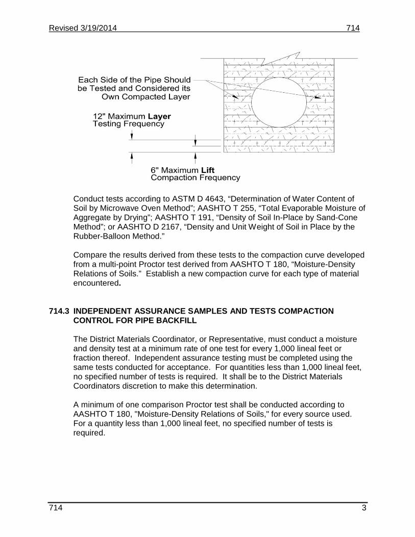
Revised 3/19/2014 714
Conduct tests according to ASTM D 4643, “Determination of Water Content of Soil by Microwave Oven Method”; AASHTO T 255, “Total Evaporable Moisture of Aggregate by Drying”; AASHTO T 191, “Density of Soil In-Place by Sand-Cone Method”; or AASHTO D 2167, “Density and Unit Weight of Soil in Place by the Rubber-Balloon Method.”
Compare the results derived from these tests to the compaction curve developed from a multi-point Proctor test derived from AASHTO T 180, “Moisture-Density Relations of Soils.” Establish a new compaction curve for each type of material encountered.
714.3 INDEPENDENT ASSURANCE SAMPLES AND TESTS COMPACTION
CONTROL FOR PIPE BACKFILL
The District Materials Coordinator, or Representative, must conduct a moisture and density test at a minimum rate of one test for every 1,000 lineal feet or fraction thereof. Independent assurance testing must be completed using the same tests conducted for acceptance. For quantities less than 1,000 lineal feet, no specified number of tests is required. It shall be to the District Materials Coordinators discretion to make this determination.
A minimum of one comparison Proctor test shall be conducted according to AASHTO T 180, "Moisture-Density Relations of Soils," for every source used. For a quantity less than 1,000 lineal feet, no specified number of tests is required.
714 3

Revised 3/19/2014 714 714.4 INDEPENDENT ASSURANCE (IA) SAMPLES AND TESTS FOR
UNDERDRAIN
Granular Fill Material:
District Laboratory Testing: The District Materials Coordinator obtains one sample from each project for sieve analysis. Obtain the sample according to AASHTO T 2, “Sampling of Aggregate,” split the sample according to AASHTO T 248, “Reducing Samples of Aggregate to Testing Size,” and run the sieve analysis according to AASHTO T 11, “Materials Finer than No. 200 Sieve in Mineral Aggregate by Washing,” and AASHTO T 27, “Sieve Analysis of Fine and Coarse Aggregate.”
714 4

720.01
Section 720
MONUMENTS AND RIGHT OF WAY MARKERS
720.01 DESCRIPTION.
This work consists of furnishing and installing concrete monuments and right of way markers.
720.02 ACCEPTANCE.
Material covered by this section is accepted by certification.

722.02
Section 722
MANHOLES, CATCH BASINS, AND INLETS
722.01 DESCRIPTION.
This work consists of constructing and adjusting manholes, catch basins, and inlets, including the furnishing or resetting of necessary metal frames, covers or grates, valve boxes, or other accessories to new lines and grades where such accessories are public property.
722.02 ACCEPTANCE.
Acceptance procedures for cast-in-place concrete are outlined in Section 602 of this manual.
If precast concrete, see Quality Assurance Program for Prestressed and Precast Concrete Products in Appendix A of this manual.
The brick and block are accepted by certification. Examine in the field for freedom from cracks, warpage, stones, pebbles, or particles of lime that would affect the serviceability of the brick . Check brick for a rectangular cross section with substantially square corners.
Reinforcing steel is accepted by certification.
Cast iron frames, tops, covers and grates are accepted by certification.
Revised 5-99

724.01
Section 724
WATER MAINS, WATER LINES, AND SEWER LINES
724.01 DESCRIPTION.
This work consists of furnishing and installing water and sewer lines and appurtenances of the types and sizes required, in full compliance with the requirements of the North Dakota State Plumbing Code, the North Dakota State Health Department, and applicable City ordinances.
724.02 ACCEPTANCE.
All materials (other than concrete) are accepted by certification.

740.02
Section 740
DAMPPROOFING AND FABRIC WATERPROOFING
740.01 DESCRIPTION.
This work consists of furnishing materials and placing dampproofing and fabric waterproofing on surfaces and areas specified.
740.02 ACCEPTANCE.
All materials are accepted by certification.

744.01
Section 744
INSULATION BOARD (POLYSTYRENE)
744.01 DESCRIPTION.
This work consists of furnishing and installing extruded polystyrene insulation board.
744.02 ACCEPTANCE.
The insulation board is accepted by certification.

Section 748
Section 748
CURB AND GUTTER
748.01 DESCRIPTION.
This work consists of constructing curb, gutter, or combination curb and gutter.
748.02 REQUIRED TESTS AND FREQUENCY.
A. Acceptance Samples and Tests--Field Laboratory Testing. Perform sufficient sieve analysis of aggregates taken at an appropriate stage to ensure the continuing quality as specified (see Section 816.4 of this manual for procedures). The type of mixing operation determines the sample timing, place, and frequency. This is at the discretion of the engineer/manager.
Report the results on SFN 10072 and submit to the District Materials Coordinator.
Perform one moisture test on aggregates per day (see Section 816.04 A. of this manual for procedure).
Submit a minimum of one random sample of cement per project to the Materials and Research Division.
B. Independent Assurance Samples and Tests
1. District Laboratory Testing. The District Materials Coordinator or adesignated representative must obtain these samples and conduct thesetests.
Obtain one sieve analysis and physical properties sample of coarse andone sample of fine aggregate for each 150 C.Y. of concrete.
Cast one set of compression test cylinders for each 200 C.Y. of concrete(see Section 802.03 E. of this manual for procedure).
Revised 3-2000

748.02 C.
2. Materials and Research Division Testing. Submit one sample for everysource of water used. Water known to be of potable quality may be usedwithout testing.
Submit one sample for each lot of hot applied joint sealant used.
C. OTHER. The precast concrete curbing is accepted by certification. Inspect each section for damage from transit. Do not install any section that has serious damage.
Reinforcing steel, cold applied joint material, joint filler, and curing materials are accepted by certification.
Revised 3-2000

750.02
SECTION 750
SIDEWALKS AND DRIVEWAYS
750.01 DESCRIPTION.
This work consists of constructing concrete sidewalks and driveways.
750.02 ACCEPTANCE.
These items are cast in-place. The acceptance procedures are the same as for cast in-place concrete curbing outlined in Section 748 of this Manual.

Section 752
FENCING--INSTALLATION AND RESETTING
752.01 DESCRIPTION.
This work consists of constructing fences and gates including the removal of existing fences and resetting of fences in locations shown on the Plans or as directed by the engineer/manager.
752.02 REQUIRED TESTS AND FREQUENCY.
A. Acceptance Samples and Tests--Field or District Laboratory Testing. Chain link fence, barbed wire, woven wire, staples, and posts (both steel and wood) are accepted by certification.
Examine each spool of barbed wire for the following markings: 1. Style of barbed wire.2. Class of coating3. Length4. ASTM A 1215. Name or mark of manufacturer.
If this information is lacking, do not install the wire until a determination is made that it meets specification requirements.
Inspect the steel posts for damaged coating. Touch up damaged coatings. Inspect wood posts for size, soundness, and straightness as outlined in Section 860 of the Standard Specifications.
The woven wire and chain link fencing must be tightly rolled and firmly tied. Each roll must carry a tag showing:
1. Style of fence.2. Length of fencing on the roll.3. Class of coating.4. ASTM or AASHTO designation.5. Name or mark of the manufacturer.
754.02 A.3
Section 754
HIGHWAY SIGNS
754.01 DESCRIPTION.
This work consists of furnishing, fabricating, and installing highway signs, delineators, and supporting structures.
754.02 ACCEPTANCE.
All metal items and sheeting are accepted by certification and inspected for compliance according to Section 754 of the Standard Specifications.
A. Concrete Testing.
1. Field Tests. Obtain one sieve analysis sample of each size aggregate for
each 150 C.Y. of concrete.
Perform one air, slump, and yield test near the beginning of the operation and when approximately one-half of the Plan quantity of concrete has been placed.
Cast compression test cylinders per Table 1 in Section 602 of this Manual.
A delivery ticket must accompany each load of concrete. The producer must state the class of concrete being furnished, and the weights of cement, aggregate, and water used in the batch at the time of batching.
Submit one random sample of cement per project to the Materials and Research Division.
2. District Laboratory Tests. Obtain one sieve analysis and physical properties
sample of both fine and coarse aggregate for each 150 C.Y. of concrete.
3. Materials and Research Division Tests. Obtain one sample for each source of water used. Water known to be of potable quality may be used without testing.
Reinforcing steel is accepted by certification.
Revised 5-99

762.01
Section 762
PAVEMENT MARKING
762.01 DESCRIPTION.
This work shall consist of furnishing and installing specified pavement markings at the designated locations.
762.02 REQUIRED TESTS AND FREQUENCY.
A. Acceptance Samples and Tests--Field or District Laboratory Testing. All items
are accepted by certification. B. Materials and Research Division Testing. Submit to the Materials and
Research Division for testing 100 pounds of glass beads for every 10,000 pounds shipped. Submit Glass bead samples in unopened bags.
762.03 SAMPLING, TESTING, AND ACCEPTANCE.
A. Sampling Pavement Marking Paint from 55 gallon Drums.
1. Conditions. Temperature range of 60° to 80°F.
2. Sampling. All sampling equipment, sample cans, and labor is provided by
the Contractor. Randomly select the two 55-gal drums from each lot to be sampled. Record the date of manufacture and the lot number.
Open the selected drums and stir any settlings with a boat paddle, making sure to loosen the settlings on the bottom of each drum.
Mix the paint for 5 minutes with an electric or air-driven mechanical mixer affixed to the drum. After the 5-minute mixing period, check for settlings on the bottom of the drum by stirring with a boat paddle.
If no settlings are present, obtain a 1-pt paint sample from each drum. When sampling water-borne paint use epoxy-lined cans.
If settlings are present, continue to stir with the paddle to loosen the settlings and engage the mechanical mixer for an additional 5 minutes of mixing. Obtain samples after this mixing.
Ship the samples in well sealed cans to the Materials and Research Division.
Revised 4-97

762.03 B.1. B. Glass Beads Sampling and Testing. Conduct sampling and testing according
to AASHTO M 247. The summary and exceptions follow:
1. Sampling. If packaged in 50-lb bags, sample the glass beads randomly at a ratio of 100 lbs of sample (in full bags) per 10,000 lbs shipped. Submit the total sample or reduce with a sample splitter to an approximate size of one liter.
When beads are delivered in drums, obtain one sample per 10,000 lbs shipped or fraction thereof. Randomly select drums for testing. Obtain the sample by inserting a sample probe vertically into the drum. Insert the probe as many times as necessary to obtain a sample approximately one liter in size.
Submit the samples and certification to the Materials and Research Division.
Revised 4-97

764.01
Section 764
GUARDRAIL
764.01 DESCRIPTION.
This work consists of installing, removing, and resetting guardrail and box beam median barrier.
764.02 ACCEPTANCE.
All materials covered by this Section are accepted by certification.

770.02 A.
Section 770
HIGHWAY LIGHTING 770.01 DESCRIPTION.
This work consists of furnishing and installing highway and street lighting.
770.02 REQUIRED TESTS AND FREQUENCY.
A. Acceptance Samples and Tests--Field or District Laboratory Testing. Shop
drawings are required for the following items:
1. Conductors. 2. Pull Boxes. 3. Feed Point Equipment including:
a. Circuit breakers (enclosed in a load center-type panel board). b. Enclosed relay (normally open). c. Cabinet. d. Photoelectric cell.
4. Light Standard including: a Luminaries b. Fusehold. c. All necessary calculations and drawings used in the design of these
poles. 5. Sign Lighting including:
a. Loadcenter. b. Luminaire. c. Ballast.
6. High Mast Lighting Assembly including: a. Pole. b. Lowering Device. c. Head Frame Assembly d. Luminaire Ring Assembly e. Winch and Hoisting Assembly including all cables. f. Portable Power Unit. g. Luminaries. h. All necessary calculations and drawings used in designing high mast
poles.
The shop drawings are to indicate the quality of the proposed material. The materials are considered for Specification compliance after review by the project engineer/manager.

772.01
Section 772
HIGHWAY TRAFFIC SIGNALS
772.01 DESCRIPTION.
This work consists of furnishing and installing flashing beacons and traffic signals.
772.02 REQUIRED TESTS AND FREQUENCY.
A. Acceptance Samples and Tests--Field or District Laboratory Testing. Shop drawings are required for the following items:
1. Conductors.2. Pull Box.3. Saw Slot Sealant.4. Feed Point Equipment including:
a. Safety switch and lighting protection device.b. Flasher.c. Time Clock.d. Cabinet.
5. Traffic Signal Standards including all necessary calculations and drawingsused in designing these poles.
6. Combination Standards including all necessary calculations and drawingsused in designing these poles.
7. Traffic Signal Heads.8. Beacon Heads.9. Pedestrian Signal Heads.10. Pedestrian Push Button.11. Detector Cabinet.12. Traffic Signal Controller with all components including, when required:
a. Controller.b. Flasher.c. Conflict Monitor.d. Coordination Equipment.e. External Logic Unit.f. Solid State Load Switches.g. Detector Amplifier.h. Lightning Protection Device.i. Cabinet.
13. Emergency Vehicle Pre-Emotion Equipment.
The shop drawings are to indicate the quality of the proposed materials. The materials are considered for Specification compliance after review by the construction engineer. An approved shop drawing or catalog description is

772.02 A.
considered acceptance of each respective material. Inspect for obvious defects on the project.
Conduit is accepted by certification.
Paint for traffic signals, conduit and saw slot sealant are accepted by certification.
Revised 6-97


Intentionally Left Blank


Intentionally Left Blank


Intentionally Left Blank


Intentionally Left Blank


Intentionally Left Blank


FIELD SAMPLING AND TESTING MANUAL
TESTING PROCEDURES FOR ALL TESTS

Intentionally Left Blank

______________________________________________________________________ 3/13/2019 Revised Procedures Page 1 of 2
TESTING PROCEDURES FOR ALL TESTS
TABLE OF CONTENTS
ND T 2 Sampling Of Aggregates ND T 11 Materials Finer than No. 200 Sieve in Mineral Aggregates by Washing ND T 23 Making and Curing Concrete Test Specimens in the Field ND T 27 Sieve Analysis of Fine and Coarse Aggregates ND T 84 Specific Gravity and Absorption of Fine Aggregate ND T 85 Specific Gravity and Absorption of Coarse Aggregate ND T 87 Dry Preparation of Disturbed Soil and Soil Aggregate Samples for Test ND T 89 Determining the Liquid Limit of Soils ND T 90 Determining the Plastic Limit and Plasticity Index of Soils ND T 99/T 180 Moisture-Density Relations of Soils ND T 113 Lightweight Pieces in Aggregate ND T 119 Slump of Hydraulic Cement Concrete ND T 121 Density (Unit Weight), Yield, and Air Content (Gravimetric) of Concrete ND T 141 Sampling Freshly Mixed Concrete ND T 152 Air Content of Freshly Mixed Concrete by the Pressure Method ND T 166 Bulk Specific Gravity of Compacted Asphalt Mixtures Using Saturated Surface-Dry Specimens ND T 176 Plastic Fines in Graded Aggregates and Soils by Use of the Sand Equivalent Test ND T 191 Density of Soil In-Place by the Sand-Cone Method ND T 209 Theoretical Maximum Specific Gravity and Density of Hot Mix Asphalt

______________________________________________________________________ 3/13/2019 Revised Procedures Page 2 of 2
ND T 217 Determination of Moisture in Soils by Means of a Calcium Carbide Gas Pressure Moisture Tester (Speedy) ND T 224 Correction for Coarse Particles in the Soil Compaction Test ND T 245 Resistance to Plastic Flow of Bituminous Mixtures Using Marshall Apparatus ND T 248 Reducing Samples of Aggregate to Testing Size ND T 255 Total Evaporable Moisture Content of Aggregate by Drying ND T 265 Laboratory Determination of Moisture Content of Soils ND T 304 Uncompacted Void Content of Fine Aggregate ND T 309 Temperature of Freshly Mixed Hydraulic Cement Concrete ND T 312 Preparing and Determining Density of Hot Mix Asphalt (HMA) Specimens by Means of the Superpave Gyratory Compactor ND T 318 Water Content of Freshly Mixed Concrete Using Microwave Oven Drying ND D 2167 Density and Unit Weight of Soil in Place by the Rubber-Balloon Method ND D 4643 Microwave Method of Drying Soils ND D 4791 Flat Particles, Elongated Particles, or Flat and Elongated Particles in Coarse Aggregate NDDOT 1 Sampling of Bituminous Materials NDDOT 2 DELETED 3/13/2019 NDDOT 3 Shale, Iron Oxide Particles, Lignite and Other Coal, Soft Particles, Thin or Elongated Pieces NDDOT 4 Percentage of Fractured Particles in Coarse Aggregate NDDOT 5 Sampling and Splitting Field Verification Hot Mix Asphalt (HMA) Samples NDDOT 6 Settlement Test for Liquid Membrane Curing Compound

________________________________________________________________ND T 2
___________________________________________________________________ 3/13/2019 Revised ND T 2 Page 1 of 4
ND T 2 – SAMPLING OF AGGREGATES SCOPE
This test defines the procedures used to obtain samples that will show the nature and condition of the materials which they represent. For equipment specification details consult the current AASHTO edition.
REFERENCED DOCUMENTS
AASHTO T 2, Sampling of Aggregates ND T 248 and AASHTO T 248, Reducing Samples of Aggregate to Testing Size
TERMINOLOGY
Maximum Size of Aggregate – the smallest sieve opening through which the entire amount of aggregate is required to pass. Nominal Maximum Size – the smallest sieve opening through which the entire amount of the aggregate is permitted to pass. Maximum Aggregate Size (SuperPave) – one size larger than the nominal maximum aggregate size. Nominal Maximum Aggregate Size (SuperPave) – one size larger than the first sieve that retains more than 10% aggregate.
APPARATUS
Containers, pails or bags Shovel Scoop or spoon Brush Sampling tubes
TEST SPECIMEN
The sample size is based on the type and number of tests to be performed. The following table gives the approximate sample size required for different aggregate sizes.

________________________________________________________________ND T 2
___________________________________________________________________ 3/13/2019 Revised ND T 2 Page 2 of 4
SIZE OF SAMPLE Nominal Size of
AggregateA Approximate Minimum Mass of
Field SamplesB Fine Aggregate
No. 8 (2.36 mm) 25 lbs (10 kg)
No. 4 (4.74 mm) 25 lbs (10 kg)
Coarse Aggregate
3/8" (9.5 mm) 8 lbs ( 4 kg)
1/2" (12.5 mm) 16 lbs ( 8 kg)
5/8" (16.0 mm) 30 lbs (15 kg)
3/4" (19.0 mm) 44 lbs (20 kg)
1" (25.0 mm) 88 lbs (40 kg)
1½" (37.5 mm) 132 lbs (60 kg) A For processed aggregate, use the nominal maximum size
as indicated by the appropriate specification or description. If the specification or description does not indicate a nominal maximum size, use the maximum size (sieve indicating 100% passing).
B For combined coarse and fine aggregates, e.g., base or
subbase, the minimum weight shall be the coarse aggregate minimums plus 25 lbs (10 kg).
PROCEDURE
When practicable, samples shall be obtained from the finished product. Sampling requires a number of individual samples that are combined to make a composite sample. Reduce the sample to the required size by quartering or splitting in accordance with ND T 248.

________________________________________________________________ND T 2
___________________________________________________________________ 3/13/2019 Revised ND T 2 Page 3 of 4
• SAMPLING FROM ROADWAY:
When sampling from the roadway material or in-place, take samples from at least three approximately equal increments across the roadway. Obtain samples from the full depth of the course. Take care to avoid including material from the underlying subgrade or base course. Combine the samples to form a composite sample.
• SAMPLING FROM A FLOWING AGGREGATE STREAM:
Obtain at least three approximately equal increments and combine to form the required size sample. Collect the samples in a pan or by use of a sampling device. Take the samples from the entire cross section as it is being discharged. The receptacle should be of sufficient size to intercept the entire stream and hold the material without overflowing.
• SAMPLING FROM A WINDROW:
Sample the windrow by removing the top one-foot of material and obtain part of the sample from each side. Avoid the segregated coarser material at the bottom of the side slope. Combine three samples to form a composite sample.
• SAMPLING FROM A CONVEYOR BELT:
Obtain at least three approximately equal increments and combine to form the required size sample. Stop the conveyor belt and clean off a section of material from the belt. Insert a template that conforms to the shape of the belt. Carefully remove all the material from the template. Use a scoop to remove as much of the material as possible. A brush and dustpan may be used to remove the fine material. Make sure to include all of the fine material. Space the three samples apart.
• SAMPLING FROM A STOCKPILE:
Segregation often occurs when materials are stockpiled; therefore, it is difficult to ensure unbiased samples from stockpiles. For coarse or mixed coarse and fine aggregate, make every effort to enlist the services of power equipment to develop a separate, small sampling pile composed of material from various levels and locations in the main pile. Combine several increments to compose the sample.
Where power equipment is not available, combine material from at least three increments: the top third, middle third, and bottom third of the pile. Insert a board vertically into the pile just above the sampling point to aid in preventing further segregation. Remove the outer layer, which may be segregated, and sample the material beneath.

________________________________________________________________ND T 2
___________________________________________________________________ 3/13/2019 Revised ND T 2 Page 4 of 4
An alternate sampling method is to insert a sampling tube into the pile at a minimum of five random locations to extract material to form a sample. Sampling tubes are approximately 1¼" (minimum) in diameter by 6' (minimum) in length
• SAMPLING FROM A TRUCK:
For coarse aggregate or composite of coarse and fine aggregate, sample from trucks. Take samples from a minimum of three trenches. Dig trenches across the truck box at points on the surface that appear to be representative of the material. Make the trench bottom approximately level, at least one-foot wide and one-foot below the surface of the aggregate. Take equal portions of material by pushing the shovel downward into the material in the bottom of the trench at three equally spaced locations. Do not scrape the material horizontally. Combine the nine portions (minimum) to form the combined sample from the truck.
For sampling the fine aggregate, insert a sampling tube at a minimum of five locations. Sampling tube should be a minimum of 1¼" in diameter by 6' in length.
NOTES
It is desirable to sample any material as near as possible to, if not at, the final in-place position. Hierarchies of preferred sampling locations are in-place, windrow, conveyor belt, flowing stream, truck box, or stockpile.

2/13/2015 Revised ND T 11
______________________________________________________________________ ND T 11 Page 1 of 3
ND T 11 - MATERIALS FINER THAN NO. 200 (75 µm) SIEVE IN MINERAL AGGREGATES BY WASHING
Conduct this procedure according to ND T 11.
The AASHTO standard test procedure reports the percentage of material finer than the No. 200 sieve to the nearest 0.1%, except if the result is 10% or more, than it reports to the nearest whole number. The NDDOT modification reports the accuracy to the same significant digit as the specification for the class of aggregate.
Consult the current edition of AASHTO for procedure in its entirety and the equipment specification details.
SCOPE
This test method determines the amount of material finer than the No. 200 sieve in aggregate by washing. Procedure A shall be used unless otherwise specified.
When accurate determinations of material finer than the No. 200 in fine or coarse aggregate are desired, this test method is used on the aggregate sample prior to dry sieving according to ND T 27. The results of this procedure are included in the calculations for ND T 27.
REFERENCED DOCUMENTS
ND T 2 and AASHTO T 2, Sampling Aggregates AASHTO T 11, Materials Finer than No. 200 Sieve by Washing ND T 27 and AASHTO T 27, Sieve Analysis of Fine and Coarse Aggregate ND T 248 and AASHTO T 248, Reducing Samples of Aggregate to Testing Size ND T 255 and AASHTO T 255, Total Evaporable Moisture Content of Aggregate by Drying
APPARATUS
Balance Sieves: No. 16 and No. 200 Sample splitter Oven Washing container
Spoon

2/13/2015 Revised ND T 11
______________________________________________________________________ ND T 11 Page 2 of 3
TEST SPECIMEN
Obtain sample according to ND T 2. Thoroughly mix and reduce according to ND T 248. Test specimen shall be a representative sample based on the following table.
Nominal Maximum Size Minimum Mass
No. 4 (4.75 mm) or smaller 300 g
3/8" (9.5 mm) 1000 g
3/4" (19.0 mm) 2500 g
1½" (37.5 mm) 5000 g
The sample size required for this test is a minimum after drying.
PROCEDURE
Record all information on SFN 9987 or SFN 2455. Weights are recorded to the nearest 0.1 g. Oven dry the sample according to ND T 255 at a temperature of 230 ± 9°F (110 ± 5°C). Weigh and record as original weight of sample.
Place the sample into the washing container and add sufficient water to cover. Stir and agitate the sample with the spoon until all fines are in suspension. Slowly decant the water into the stacked No. 16 and No. 200 sieves being careful not to lose the coarser material of the sample.
Add a second charge of water to the sample in the washing container and stir, agitate, and decant. Repeat this process until the wash water is clear. Wash any remaining material on the sieve back into the sample. Do not decant any water from the container except through a No. 200 sieve to avoid loss of material. Any remaining water should be evaporated by the drying procedure. Oven dry the sample according to ND T 255 at a temperature of 230 ± 9°F (110 ± 5°C). Weigh and record as weight after wash.

2/13/2015 Revised ND T 11
______________________________________________________________________ ND T 11 Page 3 of 3
CALCULATIONS
If this test has been ran for the purpose of accurate determination of material finer than the No. 200 in fine or coarse aggregate, the results of this procedure are determined by the calculations for ND T 27 on SFN 9987. To calculate material passing the No. 200 sieve as percent of the total sample for coarse aggregate for concrete, subtract dry weight after washing from weight of total sample and divide result by weight of total sample. Multiply this result by 100 and record as material passing No. 200 sieve as percent of total sample. The equation is as follows:
A = [(B-C)/B] x 100 A = percent of material finer than No. 200 sieve by washing B = weight of total sample before washing C = weight of dry sample after washing REPORT
Report the percent of material finer than the No. 200 sieve to the same significant digit as the specification for the class of aggregate.
NOTES
A piece of rubber tubing may be attached to a water faucet and be used to rinse material from the sieves. The velocity of the water, which may be increased by pinching the tubing, should not be sufficient to cause splashing of the sample over the sides of the sieve.
CALIBRATION A calibration check of the equipment should be performed annually as a
minimum, or whenever damage or repair occurs.

Intentionally Left Blank

2/13/2015 Revised ND T 23
ND T 23 Page 1 of 6
ND T 23 - MAKING AND CURING CONCRETE TEST SPECIMENS IN THE FIELD
Conduct this procedure according to ND T 23.
Consult the current edition of AASHTO standard procedure in its entirety and equipment specification details.
SCOPE
This method covers procedures for making, curing, and transporting cylinder or flexural beam specimens made from representative samples of fresh concrete under field conditions.
REFERENCED DOCUMENTS
AASHTO T 23, Making and Curing Concrete Test Specimens in the Field ND T 141 and AASHTO T 141, Sampling Freshly Mixed Concrete ND T 309 and AASHTO T 309, Temperature of Freshly Mixed Hydraulic-Cement Concrete ND T 119 and AASHTO T 119, Slump of Hydraulic Cement Concrete ND T 152 and AASHTO T 152, Air Content of Freshly Mixed Concrete by Pressure Method AASHTO M 201, Mixing Rooms, Moist Cabinets, Moist Rooms, and Water Storage Tanks Used in the Testing of Hydraulic Cements and Concretes
APPARATUS
Cylinder molds Beam molds Tamping rods Internal vibrator Mallet Wood float Trowel Scoop Shovel Sampling and mixing receptacle Calcium hydroxide storage tank
SAMPLING AND PREPARING CONCRETE SAMPLE
Obtain a concrete sample according to ND T 141. Obtain at least a 1-cu.ft. sample.

2/13/2015 Revised ND T 23
ND T 23 Page 2 of 6
Transport the sample to the test specimens molding site and re-mix with a shovel to assure maximum uniformity. Protect the sample from moisture loss from the time the sample is taken to the time it is molded. Do not exceed 15 minutes. Determine the temperature according to ND T 309, slump to ND T 119 and air content according to ND T 152. The results of the slump test will determine the method of consolidation. Rod or vibrate concrete with a slump greater than 1" (25 mm). Vibrate concrete with a slump of 1" (25 mm) or less.
MOLDING AND CURING - GENERAL
Mold specimens on a level, rigid, horizontal surface that is free from vibration and other disturbances, and as near as practical to the place where they will be stored for the initial curing period. The supporting surface on which specimens will be stored for initial curing must be level to within 1/4" (6 mm) per foot. Remix the concrete before molding. Mold the specimens by placing the concrete in the number of layers indicated by the consolidation method. Move the scoop or shovel around the perimeter of the mold opening to distribute the concrete uniformly. Further distribute the concrete with a tamping rod. Attempt to place the final layer to exactly fill the mold after compaction. If casting the specimens at the place of initial curing is not practicable, move them to the place of storage immediately after being struck off. Take care to avoid marring the surface when moving the specimen. If cylinders in single-use molds are moved, support the bottom. Immediately refinish if necessary.
PROCEDURE – CYLINDERS: Consolidation by Rodding:
Specimen Type and Size
Number of Layers of Approximately Equal
Depth
Number of Insertions per
Layer Cylinder Diameter:
4" (100 mm) 2 25 6" (150 mm) 3 25

2/13/2015 Revised ND T 23
ND T 23 Page 3 of 6
Tamping Rod Requirements for Cylinder and Beam Molds:
Cylinder Mold Diameter or Beam
Mold Width
Tamping Rod
Diameter
Tamping Rod
Length < 6" (< 150 mm) 3/8" (10 mm) 12" (300 mm)
6" (150 mm) 5/8" (16 mm) 20" (500 mm)
Mold the test specimen in layers of approximately equal volume dependent of mold size. Rod each layer with 25 strokes of the tamping rod. Evenly distribute the strokes over the cross section of the mold. Add representative concrete to fill any surface voids during final consolidation.
Rod the first layer throughout its depth. For the following layers, penetrate the underlying layer about 1" (25 mm) with each stroke. After each layer is rodded, tap the outside of the mold 10 to 15 times with a mallet to close any voids. If using a single-use mold, tap with an open hand.
Consolidation by Internal Vibration:
Specimen Type and Size
Number of Layers of Approximately
Equal Depth Number of
Insertions per Layer Cylinder Diameter:
4" (100 mm) 2 1 6" (150 mm) 2 2
Fill molds in two approximately equal layers. Do not overfill the second layer by more than 1/4" (6 mm). After each layer is added insert the vibrator at two different points. Allow to penetrate through the first layer. Do not allow the vibrator to rest on the bottom or sides of the mold. Take care when removing to avoid leaving air pockets. The second layer vibration should penetrate the first layer approximately 1" (25 mm). Follow each layer by tapping the outside of mold at least 10 times with mallet. Tap single-use molds with an open hand. Add representative concrete to fill any surface voids during final consolidation.
Vibrate only long enough to achieve proper consolidation. Generally no more than 5 seconds should be required for each insertion.
Finishing: After consolidating the top layer, strike off any excess concrete with the tamping rod when possible, or a wood float or trowel. The finished surface should have

2/13/2015 Revised ND T 23
ND T 23 Page 4 of 6
no projections or depressions greater than 1/8" (3 mm). Cover the cylinder with a mold cover or a plastic bag drawn down snugly and fastened with a rubber band or string.
PROCEDURE - BEAMS Consolidation by Rodding:
Specimen Type and Size
Number of Layers of Approximately
Equal Depth Number of Insertions
per Layer Beam Width: 6" to 8" (150 to 200 mm) 2 1 insertion per 2 sq.in.
> 8" (> 200 mm) 3 1 insertion per 2 sq.in.
Form the test specimen with its long axis horizontal. Place the concrete in two approximately equal layers. Move the scoop or shovel around the perimeter of the mold to ensure an even distribution.
Rod each layer once for every 2 sq.in. (13 sq.cm.) of concrete surface area. Rod the first layer through its depth. Rod the second layer through its depth and approximately 1" (25 mm) into the first layer. Tap the outside of the mold lightly 10 to 15 times with a mallet after each layer. After tapping, spade the concrete along the sides and ends of the molds with a trowel. Slightly overfill the top layer.
Consolidation by Internal Vibration:
Specimen Type and Size
Number of Layers of Approximately
Equal Depth Number of Insertions
per Layer Beam Width: 6" to 8" (150 to 200 mm) 1 6" intervals
> 8" (> 200 mm) 2 or more 6" intervals
Form test specimen with its long axis horizontal. Fill the mold in one layer. Insert the vibrator at no more than 6" (150 mm) intervals along the centerline of the length. The initial insertion point shall be a minimum of 3" (75 mm) from the end of the mold. The shaft of the vibrator shall not contact bottom or sides of the mold. Take care not to over vibrate. When removing, withdraw slowly to avoid air voids. Tap the outside of the mold at least 10 times after vibration has been completed.

2/13/2015 Revised ND T 23
ND T 23 Page 5 of 6
Finishing:
A wood float or trowel may be used to strike off the top after completing vibration. Finished surface should be level with the rim of the mold and have no projections or depressions greater than 1/8" (3 mm).
INITIAL CURING PROCEDURE
During the initial curing of up to 48 hours keep test specimens moist and at a temperature between 60° to 80°F (16° to 27°C). Appropriate temperatures may be maintained by various methods, such as if the weather is hot, cover with wet burlap or wet sand. Check the temperature several times. In cold weather some means of heating may be required. Protect test specimens from damage at all times. Cylinders may be kept moist by covering with plastic lids and placing in wood boxes or structures. If the concrete is for a specified strength of 6000 psi or greater, the initial curing temperature is between 68° and 78°F (20° and 26°C).
FINAL CURING Compression Test Cylinders:
After the initial curing remove cylinders from the molds. Within 30 minutes of removal, store in a water storage tank or moist room complying with the requirements of AASHTO M 201 for remainder of curing time. Temperatures in the required range are easy to maintain at certain times of the year. Take extra care during the heat of summer or the cold of fall and winter to maintain the specified temperature. Deliver specimens to the testing laboratory in time for them to be stored under laboratory conditions for at least 24 hours.
Field Curing: Remove the molds from the test specimens for determining when a structure may be put into service at the end of initial curing time. Store as near to the point of sampling as possible so the specimens receive the same protection from environmental elements as the portions of the structure which they represent for the remainder of their curing time.

2/13/2015 Revised ND T 23
ND T 23 Page 6 of 6
Flexural Test Beams:
Beams shall be cured the same as compression cylinders, except that they shall be stored in water saturated with calcium hydroxide at 73 ± 3°F (23 ± 2°C) for 20 hours prior to testing.
Field Curing: Cure test specimens for determining when a structure may be put into service in the same manner as the concrete in the structure. At the end of the initial 48 ± 4 hours cure time, take the specimens, still in the molds, to a location near the field laboratory. Remove the test specimens from the molds and store by placing them on the ground with their top surface up. Bank the sides and ends with earth or sand and keep damp, leaving the top surface exposed to the specified curing treatment. For 24 ± 4 hours immediately before time of testing, remove all beams from field storage and store in water saturated with calcium hydroxide at 73 ± 3°F (23 ± 2°C) to ensure uniform moisture condition.
NUMBERING AND IDENTIFYING SAMPLES
The cylinder or beam is a representation of the in-place concrete. Note the location of the concrete. Use a permanent marker to mark all cylinders and beams with numeric/alpha identification. All cylinders cast from the same concrete sample are called a set. Assign a numeric designation to each set followed by a letter designation that changes with each cylinder or beam within the set (example: a set of two 7-day and two 28-day cylinders from the same concrete sample could be numbered 1-A, 1-B, 1-C, and 1-D. The next set would be 2-A, 2-B, 2-C, etc.).
TRANSPORTATION OF SPECIMENS
Specimens must be cured and protected prior to transportation. Specimens shall not be transported until at least 8 hours after final set. Specimens must be cushioned to prevent damage from jarring. In cold weather, the specimens shall be protected from freezing. Prevent moisture loss by either wrapping in plastic or wet burlap; surrounding with wet sand; or using tight-fitting plastic caps on plastic molds. Transportation time shall not exceed four hours.
CALIBRATION
A calibration check of the equipment should be performed annually as a minimum or whenever damage or repair occurs.

2/13/2015 Revised ND T 27
______________________________________________________________________ ND T 27 Page 1 of 5
ND T 27 – SIEVE ANALYSIS OF FINE AND COARSE AGGREGATES
Conduct this procedure according to ND T 27. The AASHTO standard test procedure reports the percentage of material finer than the No. 200 sieve to the nearest 0.1%; except if the result is 10% or more, than report to the nearest whole number. The NDDOT modification is for accuracy and reports to the same significant digit as specified in the specifications for the class of aggregate.
Consult the current edition of AASHTO for procedure in its entirety and equipment specification details.
SCOPE
This test method determines the particle size distribution of fine and coarse aggregates by sieving. The No. 4 sieve is designated as the division between the fine and coarse aggregate.
REFERENCED DOCUMENTS ND T 2 and AASHTO T 2, Sampling Aggregates ND T 11 and AASHTO T 11, Materials Finer than No. 200 (75 µm) Sieve in Mineral Aggregates by Washing AASHTO T 27, Sieve Analysis of Fine and Coarse Aggregates ND T 89 and AASHTO T 89, Determining the Liquid Limit of Soils ND T 90 and AASHTO T 90, Determining the Plastic Limit and Plasticity Index of Soils ND T 248 and AASHTO T 248, Reducing Samples of Aggregate to Testing Size ND T 255 and AASHTO T 255, Total Evaporable Moisture Content of Aggregate by Drying
APPARATUS
Balance Sieves: 8" round, 12" round, or 14" square Mechanical sieve shaker Oven Bronze brush Paint brush, approximately 1" wide Sample splitters, small and large Mortar and rubber tipped pestle Spoons Large pans required for drying and handling sample

2/13/2015 Revised ND T 27
______________________________________________________________________ ND T 27 Page 2 of 5
TEST SPECIMEN
Obtain sample according to ND T 2. Thoroughly mix and reduce according to ND T 248.
PROCEDURE
Use SFN 9987 or SFN 2455 to record all information. All weights are recorded to the nearest 0.1 g. Dry the sample according to ND T 255 at a temperature of 230 ± 9°F (110 ± 5°C).
Select sieves to furnish the information required by the specifications covering the material to be tested. Use of additional sieves may be desirable to prevent the required sieves from becoming overloaded.
At the completion of the sieving operation, the quantity retained on any sieve with openings smaller than the No. 4 sieve shall not exceed 4 g/sq.in. of sieving surface area. If this occurs it is considered overloading of the sieve. The overload amount for an 8" diameter sieve is 200 g.
At the completion of the sieving operation, the quantity retained on any sieve with openings of No. 4 and larger shall not exceed 2.5 times sieve opening times effective sieve area. If this occurs, it is considered overloading of the sieve. The following table shows the maximum amount of material to be retained on a sieve before being considered overloaded.
Maximum Allowable Quantity Of Material Retained*
Sieve Opening Size 8" Diameter Sieve 14" Square Sieve
2" (50 mm) 7.9 lbs (3.6 kg) 33.7 lbs (15.3 kg)
1½" (37.5 mm) 6.0 lbs (2.7 kg) 25.4 lbs (11.5 kg)
1" (25.0 mm) 4.0 lbs (1.8 kg) 17.0 lbs (7.7 kg)
3/4" (19.0 mm) 3.1 lbs (1.4 kg) 12.8 lbs (5.8 kg)
1/2" (12.5 mm) 2.0 lbs (0.89 kg) 8.4 lbs (3.8 kg)
3/8" (9.5 mm) 1.5 lbs (0.67 kg) 6.4 lbs (2.9 kg)
No. 4 (4.75 mm) 0.7 lbs (0.33 kg) 3.3 lbs (1.5 kg) *Table 1 of the current AASHTO T 27 standard shows a complete table of different size sieves of the maximum allowable quantities of material retained on a sieve.
2/13/2015 Revised ND T 27
______________________________________________________________________ ND T 27 Page 3 of 5
Preventing overloading of material on an individual sieve can be accomplished by one of the following methods:
• Insert an additional sieve with opening size intermediate between the
sieve that may be overloaded and the sieve immediately above that sieve. • Split the sample into two or more portions, sieve each portion individually
and combine the portions retained on the sieve before calculating the percentage of the sample on the sieve.
• Use sieves having a larger frame size and providing a greater sieving
area. The portion finer than the No. 4 sieve may be reduced using a mechanical splitter. Nest the sieves in order of decreasing size of opening from top to bottom and place the sample on the top sieve. Agitate the sieves by hand or by mechanical apparatus until meeting the criteria for adequacy of sieving.
When using a mechanical shaker, place the sample in the stack of sieves and shake until not more than 0.5% by weight of the total sample passes any sieve during one minute. Approximately 10 minutes will be sufficient for most material. Use manual shaking of the material on any one sieve to check on the thoroughness of sieving by any mechanical shaker.
Remove the top sieve, brush the retained material into a pan, weigh and record. Be sure to thoroughly clean each sieve. Repeat this process with each succeeding sieve, brushing the material into individual pans, and record the non-cumulative weights.
CALCULATIONS
Add the non-cumulative weight retained on the largest sieve to the weight retained on the next smallest sieve and record in the cumulative column.
Calculate the percent retained on each sieve by dividing each weight by the original total dry weight and multiplying by 100. This is the percent retained. Subtract each of these values from 100 to obtain the percent passing each sieve. Continue this process for each sieve. The equations are as follows:
% retained on sieve = (Cumulative weight/Total weight) x 100 % passing = 100 - % retained on sieve
This calculation is completed for both the coarse and fine aggregate.

2/13/2015 Revised ND T 27
______________________________________________________________________ ND T 27 Page 4 of 5
If an accurate determination of the amount of material passing the No. 200 was accomplished by performing ND T 11, subtract the weight after wash from the original weight and record as wash loss.
Add together the cumulative weight retained on the No. 200, the weight of the Minus No. 200 material, and the wash loss, and record as the weight check.
To calculate the percent passing of the total sample for the fine portion of the aggregate, multiply the percent passing the No. 4 times the percent passing on each individual sieve in the fine aggregate portion and divide by 100. The equation is as follows:
% total sample = [(% passing No.4) x (% passing smaller sieve)]/100 Final calculations of percentages passing are reported to the nearest whole number with the exception of the No. 200, which is reported to same significant digit as specified by the specification for the class of aggregate.
For both the Plus No. 4 and Minus No. 4, compare the original weight to the weight check. Subtract the smaller value from the larger value, divide the result by the original weight, and multiply by 100, to obtain the percent difference. For acceptance purposes, the two must not differ by more than 0.3%.
NOTES
Accurate determination of material finer than the No. 200 sieve cannot be achieved by using this method alone. Test method ND T 11 for material finer than the No. 200 sieve by washing should be employed.
Sieves mounted in frames larger than standard 8" diameter are used for testing coarse aggregate to reduce the possibility of overloading the sieves.
When working with mixed materials that are coated, lumpy, or baked together, the material must be pulverized enough to separate the particles and remove the coating as much as possible. The idea is to pulverize enough to separate most of the particles, without breaking up any appreciable amount of individual material particles.
In brushing the material out of the sieves, use the bronze brush for approximately the No. 30 sieve and coarser, and the paintbrush for the finer sieves. Tapping the sieves lightly with a stick of wood on the retaining ring to facilitate removal of the particles is acceptable. Do not attempt to completely remove all the particles, but examine each sieve visually before and after sieving. The amount of aggregate particles stuck in the mesh must appear to remain approximately the same for accurate results.

2/13/2015 Revised ND T 27
______________________________________________________________________ ND T 27 Page 5 of 5
Examine the sieves constantly for damage, which will affect the test results. A common occurrence is the separation of the mesh from the side of the sieve, especially in the finer sieves. Hold the sieves up to a light to inspect for damages.
Dry the sample according to ND T 255 using an oven at a temperature of 230 ± 9°F (110 ± 5°C). If the sample is used to determine ND T 89 for liquid limit, and ND T 90 for plastic limit, the sample must be dried using an oven at a temperature of 140°F (60°C).
CALIBRATION
A calibration check of the equipment should be performed annually as a minimum, or whenever damage or repair occurs.

Intentionally Left Blank

2/13/2015 Revised ND T 84
_____________________________________________________________________ ND T 84 Page 1 of 5
ND T 84 – SPECIFIC GRAVITY AND ABSORPTION OF FINE AGGREGATE
Conduct this procedure according to ND T 84. The AASHTO standard test procedure uses a 500 mL pycnometer (flask) while the NDDOT modification uses a 1000 mL pycnometer and a glass cover plate. AASHTO uses a 1000 g sample which is soaked 15 to 19 hours. NDDOT uses an 1100 g sample which is soaked for 17±1 hours.
AASHTO specifies the aggregate is in a surface dry condition and the aggregate slumps slightly when the mold is removed. NDDOT specifies the aggregate is in a surface dry condition and 25% to 75% of the top diameter of the surface slumps when the mold is removed. AASHTO specifies the sample in the pycnometer may be immersed in circulating water to adjust its temperature to 73.4°±3°F (23±1.7°C). NDDOT requires placement of the sample in the pycnometer in a water bath for 60±15 minutes.
AASHTO specifies the calculated specific gravity be recorded to the hundredth and the calculated absorption to the tenth of a percent. NDDOT specifies the calculated specific gravity be recorded to the thousandths and the calculated absorption to the hundredth of a percent.
Consult the current edition of AASHTO for procedure in its entirety and equipment specification details.
SCOPE
This test method covers the determination of the bulk specific gravity and the apparent specific gravity on the basis of mass of saturated surface dry aggregate and absorption of a fine aggregate sample. Fine aggregate is defined as material that passes the No. 4 sieve.
REFERENCED DOCUMENTS
ND T 2 and AASHTO T 2, Sampling of Aggregates AASHTO T 84, Specific Gravity and Absorption of Fine Aggregate ND T 248 and AASHTO T 248, Reducing Samples of Aggregate to Testing Size ND T 255 and AASHTO T 255, Total Evaporable Moisture Content of Aggregate by Drying

2/13/2015 Revised ND T 84
_____________________________________________________________________ ND T 84 Page 2 of 5
APPARATUS Balance Pycnometer (1000 mL flask) and glass cover plate Metal mold in the form of a frustum of a cone Metal tamper with a mass of 340 ± 15 g and tamping face 25 ± 3 mm in diameter Pan Spoon Small fan Temperature-controlled water bath Sieves: No. 4 (4.75 m) Oven TEST SPECIMEN
Obtain sample according to ND T 2. Thoroughly mix and reduce to testing size according to ND T 248.
Test specimen shall be a representative sample of approximately 1100 g of material passing the No. 4 sieve.
FLASK CALIBRATION
Calibrate the flask by determining the weight of the flask full of distilled water at 73.4 ± 3°F (23 ± 1.7°C). Overfill the flask so the water is convexed above the brim. Very carefully slide a cover plate over the brim of the flask. The flask should be free of any air bubbles. Wipe any moisture on the outside of the flask and weigh the flask, water, and cover plate. Record this weight as weight of flask, cover plate, and water. Empty the flask and repeat the calibration. Repeated weights should agree within 0.2 g.
PROCEDURE
Record all information on SFN 2199. Weights are recorded to the nearest 0.1 g. Dry the sample according to ND T 255, at a temperature of 230 ± 9°F (110 ± 5°C). Allow the sample to cool to a comfortable handling temperature.
Place the sample in a pan, cover with distilled water, and soak for 17 ± 1 hours. After the soak period carefully remove excess water. Take care to avoid loss of any fines.

2/13/2015 Revised ND T 84
_____________________________________________________________________ ND T 84 Page 3 of 5
Spread the entire sample on a flat, non-absorbent surface and expose it to a gently moving current of warm air produced by the fan set at a low speed. Stir the sample frequently to obtain uniform drying.
The purpose of the slow, uniform drying is to bring the fines to a saturated surface dry condition. In this condition moisture fills the pores of each particle while the surface of the particle is dry. If non-uniform drying is allowed, the results may be in error because over-dried portions of the aggregate will not be saturated. Continue the process until the sample approaches a free flowing condition. It is intended the first trial of the cone test be made with some surface water in the sample.
Place the mold (large diameter down) on a smooth, level, firm, non-absorbent surface and fill with the partially dried material. Fill the cone to overflowing. Heap additional material above the top of the mold by holding the mold with cupped fingers and pouring material on top of the mold. Tamp the surface of the material in the mold 25 times with the tamper. Each drop of the tamper should start 0.2" (5 mm) above the top of the fine aggregate. Allow the tamper to fall freely during each drop. Adjust the starting height after each drop. Distribute the drop evenly over the entire surface.
Remove the material spilled around the mold and slowly lift the mold vertically.
If surface moisture is still present in the sample, the fine aggregate will retain the molded shape and additional drying is required. If the sample slumps on the first try, the material has dried past the saturated surface dry state. It is possible to get the fine aggregate too dry on the first attempt, but the test can be saved by adding a few mL of water to the sample, mixing it, covering, and allowing the sample to set for 30 minutes before rechecking. Only one recheck is permitted. Test the tamped fine aggregate at frequent intervals until 25% to 75% of the top diameter of the cone slumps. At this point the material has reached the saturated surface dry condition. Immediately weigh out exactly 500 g of the saturated surface dry material for introduction into the flask. Partially fill the flask with distilled water. Immediately introduce 500 g of the saturated surface dry material into the flask. Add distilled water until the neck of the flask is partially filled. Roll and agitate the flask to eliminate the air bubbles. Periodically stop agitating and rolling the flask to allow the air bubbles to rise to the top and be eliminated. Continue the agitating, rolling, and bubble elimination procedures until all the bubbles are eliminated. It normally takes about 15 to 20 minutes to eliminate the air bubbles.
Place the flask in a water bath at 73.4 ± 3°F (23 ± 1.7°C) for 60 ± 15 minutes. To eliminate air bubbles, periodically remove the flask from the water bath, gently agitate it, and place it back in the water bath. All the air bubbles must be removed. This requires good technique and judgment. If the air bubbles are not

2/13/2015 Revised ND T 84
_____________________________________________________________________ ND T 84 Page 4 of 5
completely removed, the results will be erratic. After the flask has been in the water bath for the specified time, remove.
After removal from the water bath, add distilled water to bring the level to the top of the flask. Overfill the flask so that the water is convexed over the brim and slide the glass cover plate along the brim. The flask should be free of any air bubbles. Wipe any moisture from the flask and weigh the flask, cover plate, sample and water. Record this weight as weight of flask, cover plate, sample, and water to top of flask.
Carefully pour the sample and the water into a tarred pan. Rinse the residue from the flask into the pan with a squeeze bottle. Oven dry the sample according to ND T 255 at a temperature of 230 ± 9°F (110 ± 5°C). Cover and allow the sample to cool to room temperature for 30 to 90 minutes. Weigh and record as weight of oven dry sample.
CALCULATIONS AND REPORTING
To calculate bulk specific gravity, divide the dry weight in air by the results of the flask filled with water plus weight of the saturated surface dry sample minus the weight of the flask with sample and water to top of flask. The equation is as follows:
Bulk Specific Gravity = A/(B + S - C) A = weight of oven dry sample B = weight of flask and cover plate filled with water C = weight of flask, cover, sample and water to top of flask S = weight of saturated surface dry sample (500 g)
Report the result to the 0.001.
To calculate bulk specific gravity (Saturated Surface Dry), divide the weight of saturated surface dry sample by the results of the flask filled with water plus weight of the saturated surface dry sample minus the weight of the flask with sample and water to top of flask. The equation is as follows:
Bulk Specific Gravity (Saturated Surface Dry) = S/(B + S - C) Report the result to the 0.001.

2/13/2015 Revised ND T 84
_____________________________________________________________________ ND T 84 Page 5 of 5
To calculate apparent specific gravity, divide the weight of oven dry sample in air by the results of the flask filled with water plus weight of oven dry sample in air minus the weight of the flask with sample and water to top of flask. The equation is as follows:
Apparent Specific Gravity = A/(B+A-C) Report the result to the 0.001.
To calculate absorption, subtract the weight of oven dry sample in air from the weight of saturated surface dry sample and divide the result by the weight of oven dry sample in air. Multiply this result by 100. The equation is as follows:
Absorption = [(S-A)/A] x 100 Report the result to the nearest 0.01%. NOTES
Dipping the tip of a paper towel into the pycnometer has been found to be useful in dispersing the foam that sometimes builds up when eliminating the air bubbles.
CALIBRATION
A calibration check of the equipment should be performed annually as a minimum, or whenever damage or repair occurs.

Intentionally Left Blank
2/13/2015 Revised ND T 85
______________________________________________________________________ ND T 85 Page 1 of 4
ND T 85 – SPECIFIC GRAVITY AND ABSORPTION OF COARSE AGGREGATE
Conduct this procedure according to ND T 85. The AASHTO standard test procedure soaks the sample for 15 to 19 hours. The NDDOT modification soaks the sample for 17±1 hours. AASHTO specifies the calculated specific gravities be recorded to the hundredth and the calculated absorption be recorded to the tenth of a percent. NDDOT specifies the calculated specific gravity to be recorded to the thousandths and the calculated absorption to the hundredth of a percent. Consult the current edition of AASHTO for procedure in its entirety and equipment specification details.
SCOPE
This test method for coarse aggregate covers the determination of bulk specific gravity, bulk specific gravity saturated surface dry, apparent specific gravity, and water absorption of coarse aggregates. Material retained on the No. 4 sieve and above is considered coarse.
REFERENCED DOCUMENTS
ND T 2 and AASHTO T 2, Sampling of Aggregates ND T 27 and AASHTO T 27, Sieve Analysis of Fine and Coarse Aggregate AASHTO T 85, Specific Gravity and Absorption of Coarse Aggregate ND T 248 and AASHTO T 248, Reducing Samples of Aggregate to Testing Size ND T 255 and AASHTO T 255, Total Evaporable Moisture Content of Aggregate by Drying
APPARATUS
Balance, equipped with apparatus for suspending sample container Suspended apparatus of the smallest practical size Water tank with overflow outlet Sieves: No. 4 (4.75 mm) or other sizes as needed Oven Thermometer Absorbent towels Sample container, either a wire basket made with No. 6 wire or finer mesh, or a bucket

2/13/2015 Revised ND T 85
______________________________________________________________________ ND T 85 Page 2 of 4
TEST SPECIMEN
Obtain sample according to ND T 2. Thoroughly mix and reduce according to ND T 248. Determine sample size needed from the following table.
Nominal Maximum Size Minimum Mass of Test Sample
1/2" (12.5 mm) 4 lbs (2 kg)
3/4" (19.0 mm) 7 lbs (3 kg)
1" (25.0 mm) 9 lbs (4 kg)
1½" (37.5 mm) 11 lbs (5 kg)
2" (50 mm) 18 lbs (8 kg)
PROCEDURE
Record all information on SFN 10081. All weights are recorded to the nearest 0.1 g.
Dry sieve all material on the No. 4 sieve. Discard all material passing the No. 4 sieve. Wash the remaining sample to remove any dust or other coatings from the surface.
Dry the sample according to ND T 255 at a temperature of 230 ± 9°F (110 ± 5°C). Then allow the sample to cool to a comfortable handling temperature. Immerse the aggregate in water at room temperature for a period of 17 ± 1 hour.
Remove the sample from the water and roll in a large absorbent cloth until all visible films of water are removed. At this point the sample is in a saturated surface dry condition (SSD). Place the sample in a container. Weigh, and record as weight of saturated surface dry sample in air. Record to 0.1% of sample mass.
After weighing, place the saturated surface dry sample in the sample basket. Immerse in water that is at a temperature of 73.4 ± 3°F (23.0 ± 1.7°C). Take care to remove all entrapped air before weighing by shaking the basket while immersed. Determine the weight and record as weight of saturated sample in water.
Remove the sample from water and place in a pan.

2/13/2015 Revised ND T 85
______________________________________________________________________ ND T 85 Page 3 of 4
Dry the sample according to ND T 255 at a temperature of 230 ± 9°F (110 ±5°C). Allow the sample to cool until comfortable to handle. Weigh and record as weight of oven dry sample in air.
CALCULATIONS AND REPORTING
• To calculate bulk specific gravity, divide the dry weight in air by the results of the saturated surface dry weight minus the weight in water. The equation is as follows:
Bulk Specific Gravity = A/(B - C) A = Weight of oven dry sample in air B = Weight of saturated surface dry sample in air C = Weight of saturated sample in water Report the result to 0.001.
• To calculate bulk specific gravity SSD, divide the saturated surface dry weight by the results of the saturated surface dry weight minus the weight in water. The equation is as follows:
Bulk Specific Gravity SSD = B/(B - C) Report the result to 0.001.
• To calculate apparent specific gravity, divide the dry weight in air by the results of the dry weight in air minus the weight in water. The equation is as follows:
Apparent Specific Gravity = A/(A - C) Report the result to 0.001.
• To calculate absorption, subtract the weight of oven dry sample in air from the saturated surface dry sample in air and divide result by the weight of oven dry sample in air. Multiply this result by 100.
• The equation is as follows: Absorption = [(B - A)/A] x 100 Report the result to the nearest 0.01%.

2/13/2015 Revised ND T 85
______________________________________________________________________ ND T 85 Page 4 of 4
NOTES
If the sample is for use in concrete mixtures in which they will be used in their natural condition, the initial drying requirement is eliminated. Also, if the surfaces have been kept continuously wet until the test, the soaking time may also be eliminated.
CALIBRATION
A calibration check of the equipment should be performed annually as a minimum, or whenever damage or repair occurs.

2/13/2015 Revised ND T 87
______________________________________________________________________ ND T 87 Page 1 of 3
ND T 87 - DRY PREPARATION OF DISTURBED SOIL AND SOIL AGGREGATESAMPLES FOR TEST
Conduct this procedure according to ND T 87.
Consult the current edition of AASHTO for procedure in its entirety and equipment specification details.
The following describes the “Alternate Method” using the No. 4 and 10 sieves. SCOPE Dry preparation of soil and soil-aggregate is used to prepare samples received
from the field for mechanical analysis, physical tests, or moisture-density relation tests.
APPARATUS Balance Oven Sample splitter Pan Pulverizing apparatus - mortar and rubber-covered pestle, or mechanical device
Sieves: 3/4" (19.0 mm), 3/8" (9.5 mm), No. 4 (4.75 mm), No. 10 (2.00 mm), No. 40 (0.425 mm)
SAMPLE SIZE The initial sample size needed will be dependent upon the tests required. For Particle Size Analysis: Material passing the No. 10 sieve is required in the amount of 110 g for sandy
soil and 60 g for silty or clayey soil. A sufficient amount of material retained on the No. 4 or No. 10 sieve is necessary to obtain a representative gradation. If the material is not being used in a base or subbase the following table (page 2) may not be needed.

2/13/2015 Revised ND T 87
______________________________________________________________________ ND T 87 Page 2 of 3
Diameter of Largest Particle Approximate Minimum Mass of Portion
3/8" (9.5 mm) 1 lb (0.5 kg)
1" (25 mm) 4.25 lbs (2.0 kg)
2" (50 mm) 8.5 lbs (4.0 kg)
3" (75 mm) 11 lbs (5.0 kg) For Physical Tests: The final amount needed is approximately 300 g of material passing the No. 40
sieve. The breakdown for each physical test is listed below.
Test Sample Size Needed
Liquid Limit ND T 89 100 g
Plastic Limit ND T 90 20 g
Shrinkage Factors 30 g
Check and Referee Tests 100 g For Moisture Density Tests: The amount needed for a sample is approximately 7 lbs (3.2 kg) or more passing
the No. 4 sieve. PROCEDURE Dry the material in air or by oven at a temperature that does not exceed
140°F (60° C). Break up the clumps of soil with a mortar and rubber covered pestle without
reducing the size of the individual grains. Split the material with a sample splitter or by quartering to obtain a representative
sample in the desired amount for testing. Weigh portion selected and record as weight of total sample. Method using No. 4 and No. 10 sieves: Separate the sample into two portions by sieving through the No. 4 sieve. Set
aside material that passes the sieve.

2/13/2015 Revised ND T 87
______________________________________________________________________ ND T 87 Page 3 of 3
Pulverize the material remaining on the No. 4 sieve until the particles are broken into separate grains.
Separate again on the No. 4 sieve. When repeated grinding produces only a
small amount of material passing the sieve, the retained material is set aside for use in coarse sieve analysis. The material passing the No. 4 sieve is added to the previously sieved material. Mix together all material passing the No. 4 sieve. Again split by the sample splitter or quartering to obtain a representative portion for the required tests.
Once again separate the material passing the No. 4 sieve into two portions by
sieving through the No. 10 sieve. Set aside material that passes the sieve. Pulverize the material remaining on the No. 10 sieve until the particles are
broken into separate grains. Separate again on the No. 10 sieve. When repeated grinding produces only a
small amount of material passing the sieve, the retained material is set aside for use in coarse sieve analysis. The material passing the No. 10 sieve is added to the previously sieved material. Mix together all material passing the No. 10 sieve.
Again split by the sample splitter or quartering to obtain a representative sample
in the desired amount for testing. Once again separate the material passing the No. 10 sieve into two portions by
sieving through the No. 40 sieve. Set aside material that passes the sieve. Pulverize the material remaining on the No. 40 sieve until the particles are
broken into separate grains. Separate again on the No. 40 sieve. When repeated grinding produces only a
small amount of material passing the sieve, discard the material that is retained on the sieve. The material passing the No. 40 sieve is added to the previously sieved material. Mix together all material passing the No. 40 sieve.
Again split by the sample splitter or quarter to obtain a representative sample in
the desired amount for testing. CALIBRATION A calibration check of the equipment should be performed annually as a
minimum, or whenever damage or repair occurs.

Intentionally Left Blank

2/13/2015 Revised ND T 89
___________________________________________________________________ ND T 89 Page 1 of 4
ND T 89 - DETERMINING THE LIQUID LIMIT OF SOILS Conduct this procedure according to ND T 89, Method B. Consult the current edition of AASHTO for procedure in its entirety and
equipment specification details. SCOPE The liquid limit of a soil is the moisture content at which the soil passes from a
plastic to a liquid state. The numerical difference between the liquid limit and the plastic limit is the
plasticity index. REFERENCED DOCUMENTS ND T 87 and AASHTO T 87, Dry Preparation of Disturbed Soils and Soil-
Aggregate Samples for Test AASHTO T 89, Determining the Liquid Limit of Soils ND T 265 and AASHTO T 265, Laboratory Determination of Moisture Content of
Soils APPARATUS Mixing dish Spatulas Liquid limit device, manual or mechanical Gauge for the liquid limit device Moisture proof container with covers Balance Oven Distilled water
Grooving tool (Either a flat or curved grooving tool may be used but interchanging grooving tools during testing is prohibited.)
PROCEDURE Take a sample of approximately 50 g from the thoroughly mixed portion of the
100 g obtained in accordance with ND T 87. The portion of the material used passes the No. 40 (0.425 mm) sieve.

2/13/2015 Revised ND T 89
______________________________________________________________________ ND T 89 Page 2 of 4
Place the sample in the mixing dish and thoroughly mix with 8 to 10 mL of distilled water by alternately and repeatedly stirring, kneading, and chopping with a spatula. Add additional water in increments of 1 to 3 mL and thoroughly mix until a stiff uniform mass of soil and water is achieved. Once testing begins, do not add additional dry soil to the moistened soil. Do not use the cup of the liquid limit device to mix the soil and water. If too much moisture has been added to the sample, the sample is to be discarded or mixed and kneaded until natural evaporation lowers the moisture content into an acceptable range.
After obtaining a uniform mass of soil and water, place a sufficient quantity of the
mixture in the cup above the spot where the cup rests on the base. Squeeze and spread the mixture level with the spatula and at the same time trim the material to a depth of 10 mm at the point of maximum thickness. Use as few strokes of the spatula as possible. Use care to prevent the entrapment of air bubbles within the mass. Return the excess soil to the mixing dish and cover to retain the moisture in the sample.
Divide the soil with a firm stroke of the grooving tool along the diameter through
the centerline of the cam follower so that a clean, sharp groove is formed. Up to six strokes from the back to front are permitted to avoid tearing the sides of the groove or slipping of the soil cake on the cup. Increase the depth of the groove with each stroke and scrape the bottom of the cup with only the last stroke.
Lift and drop the cup containing the prepared sample by turning the crank at a
rate of approximately two revolutions per second for 22 to 28 blows. If the two sides of the sample come in contact at the bottom of the groove along a distance of approximately 1/2" (13 mm) within 22 to 28 blows, stop and record the preliminary closure blow count.
Return the soil to the mixing dish, remix, and then repeat the procedure. If the
second closure occurs in the acceptable range and is within two blows of the first, record the blow count and obtain a moisture content sample. This blow count will be used in the correction calculation.
If the two sides fail to come in contact at approximately 1/2" (13 mm) by 28
blows, return the soil to the mixing dish and add additional water in increments of 1 to 3 mL. If the sides come together at approximately 1/2" (13 mm) in less than 22 blows, the soil is too wet. Discard and start over with a new 50-g sample using less water or knead the sample until natural evaporation lowers the moisture content to an acceptable range.
Observe at least two groove closures before accepting the test results as the
liquid limit. This is to ensure the accepted number of blows is truly characteristic of the soil under test.

2/13/2015 Revised ND T 89
___________________________________________________________________ ND T 89 Page 3 of 4
When two groove closures have been achieved within the requirements of the test, obtain a moisture content sample.
To obtain the moisture content sample, remove a slice of soil approximately as
wide as the spatula extending from edge to edge at right angles to the groove. Include that portion of the groove in which the material flowed together. Place in a suitable tared container and cover.
Weigh and record to the nearest 0.01 g. Return the remaining soil to the mixing dish. Determine moisture content of the
sample according to ND T 265. CALCULATIONS Calculate the percent moisture as follows:
A = [(B - C)/C] x 100 A = Percent moisture B = Mass of original sample C = Mass of dry sample Calculate moisture to the nearest 0.1%. The percent moisture is the liquid limit. Upon completion of the calculation, a correction factor is applied to determine the
liquid limit at 25 blows. The correction factor uses the percent of moisture multiplied by a factor (k) of the
second closure blow count. Calculation of the liquid limit is shown at top of next page.
Number of Blows N
Factor for Liquid Limit k
22 0.985 23 0.990 24 0.995 25 1.000 26 1.005 27 1.009 28 1.014

2/13/2015 Revised ND T 89
______________________________________________________________________ ND T 89 Page 4 of 4
Liquid Limit corrected for closure at 25 blows = (k) x (WN) k = Factor given in the table WN = Moisture content at number of blows Report the corrected liquid limit to the nearest whole number. NOTES If soil slides on the liquid limit cup surface instead of flows, return the sample to
the mixing dish, add more water, re-mix and return to the cup. Cut with the grooving tool. If the sample continues to slide on the cup at less than 25 blows, the test is not applicable and a note should be made that the liquid limit cannot be determined.
The amount of time needed for a material to absorb the water will depend on the
material being tested. Some soils are slow to absorb water and it is possible to add water so fast that a false liquid limit value is obtained.
Sandy or silty material may require less water than the initial amount of 8 to
10 mL of water, and increments of 1 to 3 mL. CALIBRATION Calibration is to be done annually as a minimum and whenever damage or repair
is needed. The center of the point of the cup, which comes in contact with the base, must be
10 ± 2 mm, above the base. The gauge is used for this measurement. Secure the adjustment plate by tightening the screws. With the gauge in place, check the adjustment by revolving the crank rapidly several times. If the adjustment is correct, a slight ringing sound will be heard when the cam strikes the cam follower. If the cup is raised off the gauge or no sound is heard, further adjustment is necessary.

2/13/2015 Revised ND T 90
______________________________________________________________________ ND T 90 Page 1 of 3
ND T 90 – DETERMINING THE PLASTIC LIMIT AND PLASTICITY INDEX OF SOILS
Conduct this procedure according to ND T 90.
Consult the current edition of AASHTO for procedure in its entirety and equipment specification details.
SCOPE The plastic limit of a soil is the lowest water content at which the soil remains
plastic.
The plasticity index of a soil is the numerical difference between the liquid limit and the plastic limit. It is the moisture content at which the soil is in a plastic state.
REFERENCED DOCUMENTS ND T 87 and AASHTO T 87, Dry Preparation of Disturbed Soil and Soil
Aggregate Samples for Test ND T 89 and AASHTO T 89, Determining the Liquid Limit of Soils
AASHTO T 90, Determining the Plastic Limit and Plasticity Index of Soils ND T 265 and AASHTO T 265, Laboratory Determination of Moisture Content of Soils
APPARATUS Mixing dish Spatula Ground glass plate or unglazed paper Plastic Limit Rolling device with unglazed paper (optional) Moisture proof sample cans (3 oz. capacity) Balance Oven Distilled water PROCEDURE Record information on SFN 9987 or SFN 10086. Material passing the No. 40 (0.425 mm) sieve prepared according to ND T 87 is
needed for this test.
2/13/2015 Revised ND T 90
______________________________________________________________________ ND T 90 Page 2 of 3
If both the liquid and the plastic limits are required, take a test sample of approximately 8 g from the thoroughly wet and mixed portion of the soil prepared for ND T 89, the liquid limit. Take the sample at any stage the sample is plastic enough to be shaped into a ball without sticking to the fingers. Set aside and allow to air dry until completion of the liquid limit test. If the sample is too dry, add more water and re-mix.
If only the plastic limit is required, take a quantity of air-dried soil weighing about
20 g and mix with distilled or tap water in the mixing dish until the sample becomes plastic enough to be easily shaped into a ball. Use a portion of this ball that weighs approximately 8 g for the test sample.
Squeeze and form the 8-g test sample into an ellipsoidal-shaped mass. Sub-
sample to 1.5g to 2 g portions and roll between the palm or fingers and the ground glass plate or piece of paper with sufficient pressure to roll the sample into a uniform thread about 1/8" in diameter throughout its length. Roll at a rate of 80 to 90 strokes per minute. A stroke is a complete forward and back motion, returning to the starting place. A plastic limit rolling device may also be used. The rolling procedure should be completed in two minutes.
When the diameter of the thread reaches 1/8", break the thread into six or eight
pieces and squeeze the pieces together between the thumbs and fingers of both hands into a roughly uniform ellipsoidal shape and re-roll. Continue this procedure until the thread crumbles under the pressure required for rolling and the soil can no longer be rolled into a thread. The crumbling may occur when the thread has a diameter greater than 1/8". This is considered a satisfactory end point provided that the soil has been previously rolled into a thread 1/8" in diameter.
Do not attempt to produce failure at exactly 1/8" in diameter by allowing the
thread to reach 1/8", then reducing the rate of rolling or the hand pressure, or both, and continuing the rolling without further deformation until the thread falls apart. It is permissible to reduce the total amount of deformation for feeble plastic soils by making the initial diameter of the ellipsoidal shaped mass near the required 1/8" final diameter.
Gather the portion of the crumbled soil together and place in a container and
cover.
Repeat this procedure until the entire 8-g specimen is completely tested. Weigh to the nearest 0.01 g and record. Determine the moisture content according to ND T 265.

2/13/2015 Revised ND T 90
______________________________________________________________________ ND T 90 Page 3 of 3
CALCULATIONS Calculate the percent moisture as follows: A = [(B – C)/C] x 100 A = Percent moisture B = Mass of original sample C = Mass of dry sample Calculate moisture to the nearest 0.1%. The percent moisture is the plastic limit. Report the plastic limit to the nearest whole number. PLASTICITY INDEX CALCULATION The plasticity index of soil is the difference between its liquid limit and its plastic
limit. Plasticity Index = Liquid Limit - Plastic Limit Report the plasticity index to the nearest whole number. NOTES
Report the plastic limit as non plastic (NP) when the plastic limit is equal to or greater than the liquid limit, or when the liquid limit or plastic limit cannot be determined.
CALIBRATION
A calibration check of the equipment should be performed annually as a minimum, or whenever damage or repair occurs.

Intentionally Left Blank

2/13/2015 Revised ND T 99 and ND T 180
____________________________________________________________________ ND T 99 and ND T 180 Page 1 of 8
ND T 99 AND ND T 180 MOISTURE-DENSITY RELATIONS OF SOILS
Conduct this procedure according to ND T 99 or ND T 180.
The NDDOT modifies this standard to only allow the use of Method A and D. Method D shall only be used in lieu of Method A when there is more than 5% by weight of material retained on the No. 4 sieve.
Method D shall be used without correction for all soil-aggregates which have all materials passing the 3/4" sieve. Corrections must be made according to ND T 224 for all materials which have 30% or less retained on the 3/4" sieve.
If the specified oversized maximum of 30% is exceeded, other methods of compaction control must be used. Consult the current edition of AASHTO for procedure in its entirety and equipment specification details.
SCOPE
The moisture-density relationship test is also called the Proctor test. This test method determines the relationship between the moisture content and the density of soils compacted in a mold. Two different standards of moisture-density relationships are presently in use by the NDDOT. They vary mainly in the compaction energy applied to the soil in the mold. The two standards and their features are summarized below.
METHOD A
FEATURE ND T 99 ND T 180
Weight of Compaction Rammer 5.5 lbs 10 lbs
Distance of Drop 12" 18"
Number of Soil Layers 3 5
Diameter of Mold 4" 4"
Soil Passing Sieve Size No. 4 No. 4
Rammer, Blows/Layer 25 25

2/13/2015 Revised ND T 99 and ND T 180
____________________________________________________________________ ND T 99 and ND T 180 Page 2 of 8
METHOD D
FEATURE ND T 99 ND T 180
Weight of Compaction Rammer 5.5 lbs 10 lbs
Distance of Drop 12" 18"
Number of Soil Layers 3 5
Diameter of Mold 6" 6"
Soil Passing Sieve Size 3/4" 3/4"
Rammer, Blows/Layer 56 56 REFERENCED DOCUMENTS AASHTO T 99 and T 180 – Moisture Density Relations of Soils
ND T 217 and AASHTO T 217 - Determination of Moisture in Soil by Means of Calcium Carbide Gas Pressure Moisture Tester (Speedy)
ND T 265 and AASHTO T 265 - Laboratory Determination of Moisture Content of Soils ND D 2167 and ASTM D 2167 - Density and Unit Weight of Soil in Place by the Rubber-Balloon Method
ND D 4643 and ASTM D 4643 - Determination of Moisture Content of Soil by Microwave Oven Heating
APPARATUS
Balance, readable to 0.01 lbs. (5 g) Oven No. 4 (4.75 mm) sieve Mixing tools Moisture sample cans with lids Straightedge, 10" long Knife Compaction equipment including density mold, base and collar, and compacting rammer and guide
SAMPLE SIZE
Method A - A representative soil sample of approximately 35 lbs (15.9 kg) is required for the Multi-Point Moisture Density Relationship Test, and approximately 7 lbs (3.2 kg) is required for the One-Point Moisture Density Relationship Test.

2/13/2015 Revised ND T 99 and ND T 180
____________________________________________________________________ ND T 99 and ND T 180 Page 3 of 8
Method D - A representative soil sample of approximately 125 lbs (55 kg) is required for the Multi-Point Moisture Density Relationship Test, and approximately 25 lbs (11 kg) is required for the One-Point Moisture Density Relationship Test.
PROCEDURE
Multi-Point Moisture Density Relationship - Mechanical and Manual
Record this information on SFN 10063, "Moisture Density Relationship Test." Calculate and record to the accuracy indicated.
If the soil is damp when received, dry until it is easily crumbled under a trowel. It can be air dried or oven dried at a temperature up to 140°F (60°C). Break up the soil chunks so that the entire sample passes through the No. 4 sieve. Avoid reducing the natural size of the particles. Discard any individual particles of material retained on the No. 4 sieve or organic material. Divide the sample into five representative samples of 7 lbs each.
Thoroughly mix the first test sample with water to dampen it approximately four percentage points below optimum moisture. A good indication of a soil being right for the first point is if the soil barely forms a “cast” when squeezed together. Specimen shall be placed in moisture proof container and covered to prevent moisture loss. Mix remaining specimens in the same manner as test sample one, increasing water content by approximately one or two percentage points (not exceeding 2.5%) over each preceding specimen. This can be accomplished by adding approximately 60 mL* of water. Allow soil samples to cure in moisture proof containers for a minimum of 12 hours.
*If using Method D, the water added to the sample must be increased from approximately 60 mL to approximately 215 mL.
Weigh the empty mold without the base plate or collar and record to the nearest 0.01 lb (5 g).
From test sample one: add sufficient material to the mold to produce a compacted layer of approximately 1-3/4" for ND T 99, or 1" for ND T 180. Gently level the soil surface in the mold. *Using a manual compaction rammer or a similar device with a 2" face (50 mm), lightly tamp the soil until it is no longer loose or fluffy. Compact the soil with **25 evenly distributed blows of the compaction rammer. After each layer, trim any soil along the mold walls that has not been compacted with a knife and distribute on top of the layer.
*When completing this process using a mechanical compactor, it is recommended to use a spare or extra replacement rammer.

2/13/2015 Revised ND T 99 and ND T 180
____________________________________________________________________ ND T 99 and ND T 180 Page 4 of 8
**If using Method D, compact the soil with **56 evenly distributed blows. When using a manual compactor, remember to hold the rammer perpendicular to the base of the mold and lift the rammer to its maximum upward position.
Repeat this procedure adding more soil from the same sample each time so that at the end of the last cycle, the top surface of the compacted soil is above the top rim of the mold when the collar is removed.
Remove the collar and trim off the extruding soil level with the top of the mold. In removing the collar, rotate it to break the bond between it and the soil before lifting it off the mold. This prevents dislodging chunks of compacted soil when lifting the collar off. The trimming consists of many small scraping motions with a knife or straightedge. After trimming the soil level with the top of the mold, clean all loose material from the outside of the mold. Weigh the soil and mold to the nearest 0.01 lb (5 g) and record. Subtract the weight of the mold from this weight and divide the result by the volume of the mold. Record results as wet density in pounds per cubic foot (pcf). Compute and record wet density to the nearest 0.1 pcf.
Wet Weight of Soil = Weight of Mold + Soil – Weight of Mold Wet Density, pcf = Wet Weight of Soil/Volume of Mold
Remove the soil from the mold and slice through the center vertically. Obtain a representative sample of approximately 100 g from one of the cut faces. Take the sample from the full length of the inside of the soil cylinder. Place the moist sample in a container, cover and weigh. Record the weight of the wet soil. Record this and all moisture weights to the nearest 0.1 g.
Dry the sample to a constant weight according to ND T 265, Laboratory Determination of Moisture Content of Soils. Calculate the percent moisture to the nearest 0.1%. Compute and record dry density to the nearest 0.1 pcf. The formula is as follows:
Dry Density, pcf = (Wet Density X 100)/(100 + % Moisture)
Using specimen number two, repeat the compaction procedure previously described. Continue this process, with the remaining samples, until there is a decrease in the wet density per cubic foot.

2/13/2015 Revised ND T 99 and ND T 180
____________________________________________________________________ ND T 99 and ND T 180 Page 5 of 8
GRAPH
The objective of this procedure is to determine the maximum dry density and optimum moisture content for this particular soil. Based on the results obtained from conducting consecutive Proctors with changes in moisture, plot each test result on the cross-ruled area on the form with the moisture content plotted on the abscissa (x) and the density on the ordinate (y).
After all the results are plotted, draw a smooth flowing curve through or close to the plotted points. From the peak of the curve, select the maximum dry density and optimum moisture. Report the maximum dry density to the nearest 1-lb./cu.ft. and the optimum moisture to the nearest 0.1%.
NOTES
During compaction, the mold shall rest firmly on a dense, uniform, rigid, and stable foundation or base. This base shall remain stationary during the compaction process. Each of the following has been found to be a satisfactory base on which to rest the mold during compaction of the soil: (1) a block of concrete with a mass not less than 200 lbs (90 kg) supported by a relatively stable foundation; (2) a sound concrete floor; and (3) for field applications such surfaces are found in concrete box culverts, bridges, and pavements.
The moisture-density test is used to establish a value of density on which construction requirements can be based. It is a test conducted on a single identifiable soil and results may vary considerably between different soils.
Make every effort to space the moisture contents no further apart than 2.5% in order to accurately determine the maximum dry density and optimum moisture content.
CALIBRATION
A calibration check of the equipment should be performed annually as a minimum, or whenever damage or repair occurs.
One-Point Moisture Density Relationship with Typical Moisture-Density Curve Method
After analyzing a large number of both ND T 99 and ND T 180 moisture-density curves that generally represent statewide soil types, it was found the curves follow the trends shown on the graphs on the following pages. The graphs with the following procedure may be used in place of performing the entire moisture-density relationship test. It is recommended that the Multi-Point Moisture Density Relationship be used whenever possible.

2/13/2015 Revised ND T 99 and ND T 180
____________________________________________________________________ ND T 99 and ND T 180 Page 6 of 8
PROCEDURE The procedure that follows is written for a test using one sample of approximately
7 lbs (3.2 kg) of material. Thoroughly mix the soil sample with water and dampen it approximately to, but not over, Optimum Moisture. Conduct a Proctor test as previously described in the Multi-Point Moisture Density Relationship.
GRAPH
Use either of the following graphs, ND T 99 or ND T 180, whichever is appropriate, to locate the point defined by the two values obtained from the Proctor.
If the point lies directly on a curve, follow this curve to its peak and read off the maximum dry density and optimum moisture content. If the point lays in-between two curves, follow the two curves to their peaks and interpolate the maximum dry density and optimum moisture content. Report the maximum dry density to the nearest 1-lb./cu.ft. and report the optimum moisture to the nearest 0.1%.
NOTES
When the rubber balloon method is used for the density test, use the same material from the hole for the one-point determination. To get sufficient material, enlarge the hole after the rubber balloon test is complete and use the additional material collected.
In order to perform the test in conjunction with and at the same location as the in-place density test, there are steel-capped, wooden pedestals available to support the mold base plate. During compaction, place the mold and pedestal on firm level ground.
Perform moisture content test according to ND T 217, Determination of Moisture in Soil by Means of Calcium Carbide Gas Pressure Moisture Tester (Speedy). Or, if there is a field lab available to conduct the moisture determination, obtain the sample in the same manner described previously according to ND D 4643, Determination of Moisture Content of Soil by Microwave Oven Heating, and ND T 265, Laboratory Determination of Moisture Content of Soils. When using the graphs, a soil on the wet side of optimum could result in a substantial error when selecting the maximum dry density. Most specifications require the moisture content to be at or above optimum, thus it can be assumed that this is the condition that most samples are in. If the sample is judged to be slightly wetter than optimum, dry it to a condition slightly drier than optimum before compacting.

114
110
106
102
98
94
90
86
82
78
74
704 8 12 16 20 24 28 32 36 38
Moisture Content PercentTypical Moisture-Density Relationship Curves for ND T 99 Compaction
DryDensityPCF
100% SaturationSpecific Gravity
2.65
______________________________________________________________________ND T 99 and ND T 180
______________________________________________________________________ ND T 99 and ND T 180 Page 7 of 8

100% SaturationSpecific Gravity
2.65
134
130
126
122
118
114
110
106
102
98
94
90
864 8 12 16 20
Moisture Content Percent
24 28 32
Typical Moisture-Density Relationship Curves for ND T 180 Compaction
DryDensityPCF
2/13/2015 Revised ND T 99 and ND T 180
______________________________________________________________________ ND T 99 and ND T 180
Page 8 of 8

2/13/2015 Revised ND T 113
______________________________________________________________________ ND T 113 Page 1 of 5
ND T 113 – LIGHTWEIGHT PIECES IN AGGREGATE Conduct this procedure according to ND T 113.
The AASHTO standard test procedure uses saturated surface dry material. The NDDOT modification uses material that is dried to a constant weight. AASHTO uses material for the fine aggregate that passes the No. 4 and is retained on the No. 50 sieve. NDDOT uses material for the fine aggregate that passes the No. 4 and is retained on the No. 30 sieve. AASHTO uses a heavy liquid with a specific gravity of 2.00±0.01. NDDOT uses a heavy liquid with a specific gravity of 1.95±0.01. AASHTO does not indicate a time period for stirring and resting the sample. NDDOT agitates the fine aggregate sample for 15 seconds and then allows resting for 30 seconds before removing the lightweight pieces. This is done a maximum of three times. Consult the current edition of AASHTO for procedure in its entirety and equipment specification details.
SCOPE
This test method determines the percentage of lightweight pieces in aggregate by means of sink-float separation in a heavy liquid with a specific gravity of 1.95 ± 0.01. This test is performed separately on the coarse and fine portions of aggregate. The No. 4 sieve is designated as the division between the fine and coarse aggregate.
REFERENCED DOCUMENTS
ND T 2 and AASHTO T 2, Sampling Aggregates ND T 27 and AASHTO T 27, Sieve Analysis of Fine and Coarse Aggregate AASHTO T 113, Lightweight Pieces in Aggregate ND T 248 and AASHTO T 248, Reducing Samples of Aggregate to Testing Size ND T 255 and AASHTO T 255, Total Evaporable Moisture Content of Aggregate by Drying

2/13/2015 Revised ND T 113
______________________________________________________________________ ND T 113 Page 2 of 5
APPARATUS Balance Sieves: No. 4 (4.75 mm) and No. 30 (600 µm) Specific gravity hydrometer Zinc chloride Enamel pans Glass beaker Fine strainer Spoon Oven TEST SPECIMEN Obtain a sample according to ND T 2 and reduce according to ND T 248. Test specimen shall be a representative sample determined from the following
table:
Nominal Maximum Size of Aggregate Minimum Mass of Sample No. 4 (4.74 mm) 200 g
3/4" (19.0 mm) 3000 g
1½" (37.5 mm) 5000 g
3" (75 mm) 10,000 g
If the nominal maximum size of the aggregate to be tested is not listed above,
use the next larger size to determine the sample size. Dry the sample according to ND T 255 at a temperature of 230 ± 9°F
(110 ± 5°C). Cover the sample and cool to room temperature. Perform sieve analysis according to ND T 27. The material retained on the No. 4
sieve will be used for the coarse aggregate portion. The material passing the No. 4 and retained on the No. 30 sieve will be used for the fine aggregate portion.
PROCEDURE
Record all information on SFN 9987. All weights are recorded to the nearest 0.1 g.
Coarse Aggregate:
Weigh the sample and record as weight of Plus No. 4 material.

2/13/2015 Revised ND T 113
______________________________________________________________________ ND T 113 Page 3 of 5
Place the coarse portion into the zinc chloride solution. The volume of the liquid should be three times the volume of the aggregate. Using the strainer, skim off floating particles and place the lightweight pieces into a pan. Repeatedly agitate, rest, and remove the floating particles from the sample until no additional particles float to the surface. Use hot water to wash the zinc chloride solution from the lightweight pieces. Dry according to ND T 255 at a temperature of 230 ± 9°F (110 ± 5°C). Weigh and record as weight of lightweight pieces in Plus No. 4 material.
Fine Aggregate:
Weigh the sample and record as weight of Minus No. 4 Plus No. 30 material. Place the fine aggregate portion in a nonabsorbent container, preferably a glass beaker. Pour zinc chloride solution in with the sample. The volume of liquid should be three times the volume of the aggregate. Agitate to bring all particles into suspension by stirring for a period of 15 seconds. Allow the sample to rest for 30 seconds. After the rest period, decant the floating lightweight pieces onto a No. 30 sieve or smaller. Repeatedly agitate, rest, and remove the floating particles from the sample until no additional particles float to the surface. This process may be completed up to a maximum of three times. Use hot water to wash the zinc chloride solution off the lightweight pieces. Dry according to ND T 255 at a temperature of 230 ± 9°F (110 ± 5°C). Weigh and record as weight of lightweight pieces Minus No. 4 Plus No. 30 material.
CALCULATIONS Coarse Aggregate:
• To calculate the percent of lightweight pieces in the coarse aggregate portion, divide the weight of material that floats by the weight of the Plus No. 4 material.
The equation is as follows: A = (B/C) x 100
A = Percent of lightweight pieces in the coarse aggregate B = Weight of coarse lightweight pieces C = Weight of sample of the coarse aggregate

2/13/2015 Revised ND T 113
______________________________________________________________________ ND T 113 Page 4 of 5
• To determine the percent of coarse lightweight pieces in the total sample, multiply the percent of lightweight pieces in the coarse portion times the percent of the total sample retained on the No. 4 sieve. Multiply this result by 100. The equation is as follows:
D = (A x E)/100 D = Percent coarse lightweight pieces, total sample
A = Percent of lightweight pieces in the coarse aggregate E = Percent of total sample retained on the No. 4
Fine Aggregate:
• To calculate the percent of lightweight pieces in the fine aggregate portion, divide the weight of material that floats by the total weight of the fine portion. Multiply this result by 100.
The equation is as follows:
F = (G/H) x 100
F = Percent of lightweight pieces in fine aggregate G = Weight of fine lightweight pieces H = Weight of sample of the fine aggregate
• To determine the percent of fine lightweight pieces in the total sample, multiply
the percent of lightweight pieces in the fine portion times the result of the percent of the total sample passing the No. 4 sieve minus the percent passing the No. 30 total sample. Multiply this result by 100. The equation is as follows:
I = (F x J)/100 I = Percent fine lightweight pieces, total sample F = Percent of lightweight pieces in fine aggregate J = Result of the percent passing No. 4 minus the percent passing No. 30 total sample Report individual results to the nearest 0.01%.

2/13/2015 Revised ND T 113
______________________________________________________________________ ND T 113 Page 5 of 5
Lightweight Pieces Total Sample:
• To determine the lightweight pieces in total sample combine the percent fine lightweight pieces total sample and percent coarse lightweight pieces total sample.
The equation is as follows:
H = D + I H = Percent lightweight pieces total sample D = Percent coarse lightweight pieces, total sample I = Percent fine lightweight pieces, total sample
Report to the nearest 0.1%.
NOTES
Zinc chloride is a poison. Handle and store accordingly. Avoid zinc chloride dust or vapor from the solution by wearing an appropriate mask or work under a vent hood. The zinc chloride solution is corrosive to skin and clothing. Use safety goggles, rubber gloves, and a rubberized apron to avoid contact with skin or clothing. To prepare a zinc chloride solution, mix zinc chloride with water at room temperature at a rate of approximately 3 parts zinc chloride to 1 part water. This would be a mix proportion of about 2800 g of zinc chloride to about 1100 mL of water. During mixing the solution heats up considerably so allow time for the solution to cool to room temperature. Use a specific gravity hydrometer to adjust the specific gravity to 1.95 ± 0.01 by adding water or zinc chloride in small quantities. Adding an additional amount of zinc chloride will increase the specific gravity or adding water will decrease the specific gravity. To reuse the zinc chloride solution, check the specific gravity and adjust before each use.
CALIBRATION A calibration check of the equipment should be performed annually as a
minimum, or whenever damage or repair occurs.

Intentionally Left Blank

2/13/2015 Revised ND T 119
___________________________________________________________________ ND T 119 Page 1 of 3
ND T 119 - SLUMP OF HYDRAULIC CEMENT CONCRETE
Conduct this procedure according to ND T 119.
Consult the current edition of AASHTO for procedure in its entirety and equipment specification details.
SCOPE
A sample of freshly mixed concrete is placed and compacted by rodding in a slump cone. The mold is raised and the concrete allowed to slump. The distance between the original and displaced position of the center of the top surface is measured and reported as the slump of the concrete. The slump measurement is used as an indicator of consistency. This test is not considered applicable to non-cohesive (slumps greater than 9" or 230 mm) and non-plastic (slumps less than 1/2" or 15 mm) concrete or concrete batched with coarse aggregate over 1½" (38 mm) in size.
REFERENCED DOCUMENTS
AASHTO T 119, Slump of Hydraulic Cement Concrete ND T 141 and AASHTO T 141, Sampling Freshly Mixed Concrete
APPARATUS
Slump cone and base plate, or nonabsorbent, rigid, flat surface Scoop Ruler Sponge or brush Tamping rod, 24" (600 mm) length, and 5/8" (16 mm) diameter, rounded to a hemispherical tip
TEST SPECIMEN
Obtain a concrete sample according to ND T 141. Test must be started within five minutes of obtaining the final portion of the composite sample.
The entire test from the start of the filling through removal of the mold must be completed, without interruption, in 2½ minutes.

2/13/2015 Revised ND T 119
ND T 119 Page 2 of 3
PROCEDURE
Dampen the mold and place it on a level nonabsorbent rigid surface or the base plate provided with the cone. Hold mold in place by standing on the 2-foot pieces or by clamps if using a base plate. Immediately fill the cone in three layers. Each layer should be approximately 1/3 the volume of the cone. One third is approximately 2-5/8" (65 mm) depth; two thirds is approximately 6-1/8" (155 mm) depth. Move each full scoop around the top edge of the cone as the concrete slides from it to ensure even distribution of the concrete within the cone. Consolidate each layer of concrete 25 times with the tamping rod, rounded end down. Distribute the strokes in a uniform manner over the cross section of the cone. Incline the rod slightly to reach the perimeter. Distribute approximately half the strokes near the perimeter and progress to vertical strokes toward the center. Use a spiral pattern. Tamp the bottom layer through its full depth. Fill the second layer. Consolidate 25 times with the tamping rod. Rod the layer through its full depth and just penetrate the first layer.
Fill the final layer. Keep the concrete above the top edge of the mold at all times when rodding the third layer. Add additional concrete if needed and continue rodding. Rod through the layer but just penetrate the previous layer. After the consolidation of the top layer has been completed, strike-off the surface of the concrete with the tamping rod using a screeding and rolling motion. Continue to hold mold down firmly and remove any excess concrete from the area surrounding the base of the mold.
Loosen the clamps on the base plate if necessary, or step off the foot pieces. Remove the mold by pulling straight up and off with a steady lift. Do not use any lateral or twisting motion. The mold must be removed in 5 ± 2 seconds.
Immediately measure the slump by determining the vertical difference between the top of the mold and the displaced original center of the top surface of the specimen. If you are using a slump cone without a base plate, turn the mold upside down and lay the tamping rod across its base extending over the slumped specimen. If using a base plate, lift the handle on the base plate.
If a decided falling away or shearing off of concrete from one side or portion of the mass occurs, disregard the test and make a new test on another portion of the sample.

2/13/2015 Revised ND T 119
___________________________________________________________________ ND T 119 Page 3 of 3
REPORT Report the slump to the nearest 1/4" (5 mm).
CALIBRATION As a minimum, slump cone measurements should be verified prior to use on a
project for acceptance testing, or whenever damage or repair occurs. For independent assurance, an annual verification should be completed as a
minimum, or whenever damage or repair occurs.

Intentionally Left Blank

2/13/2015 Revised ND T 121
___________________________________________________________________ ND T 121 Page 1 of 4
ND T 121 – DENSITY (UNIT WEIGHT), YIELD, AND AIR CONTENT (GRAVIMETRIC) OF CONCRETE
Conduct this test according to ND T 121.
Consult the current edition of AASHTO for procedure in its entirety and equipment specification details.
SCOPE
This test method determines the weight per cubic foot of freshly mixed concrete and gives formulas for calculating the yield and cement content.
REFERENCED DOCUMENTS AASHTO T 19, Bulk Density (“Unit Weight”) and Voids in Aggregate ND T 119 and AASHTO T 119, Slump of Hydraulic Cement Concrete AASHTO T 121, Density, Yield, and Air Content of Concrete ND T 141 and AASHTO T 141, Sampling Freshly Mixed Concrete ND T 152 and AASHTO T 152, Air Content of Freshly Mixed Concrete by the Pressure Method APPARATUS
Balance Strike-off plate Mallet Scoop Internal vibrator Tamping rod - 24" (60 mm) in length, and 5/8" (16 mm) in diameter, rounded to a hemispherical tip Volume measure bucket - when Size 3, 4, or 5 aggregate is used in the mix, either use a 0.5 cu.ft (14 L) bucket or the air meter bowl
PROCEDURE
Sample concrete according to ND T 141. The test must be started within 5 minutes after the last sub-sample is added to the composite sample.
Slump is determined according to ND T 119. Rod concrete with a slump greater than 3". Rod or vibrate concrete with a slump of 1" to 3" (25 mm to 75 mm). Consolidate by vibrating concrete with a slump less than 1" (25 mm).

2/13/2015 Revised ND T 121
___________________________________________________________________ ND T 121 Page 2 of 4
Dampen the inside of the bucket and place on a level, firm surface. Consolidation by Rodding: Fill the bucket with concrete in three equal layers. Rod the first layer through its depth but do not forcibly strike the bottom of the bowl. Rod the following layers, penetrating approximately 1" (25 mm) into the previous layer. Uniformly rod each layer 25 times with the tamping rod, rounded end down. Follow the rodding of each layer by tapping the sides of the bowl 10 to 15 times with the mallet until the voids left by rodding are closed and to release any large air bubbles that may have been trapped. Add the final layer carefully to avoid overfilling. Take care to leave the bucket level full after rodding is complete.
Consolidation by Internal Vibration: Fill and consolidate concrete in two layers. Place all concrete in each layer before vibrating. Insert the vibrator in three different locations of each layer. Do not touch or rest on the bottom or sides of the bowl. Carefully withdraw the vibrator making sure no air pockets are left. For the second layer, the vibrator should penetrate into the first layer by about 1" (25 mm). Length of consolidation will vary depending on concrete. Do not over consolidate as it may cause segregation. Usually sufficient consolidation has occurred when the surface of the concrete becomes smooth. Take care to leave the bucket level full. Strike Off Procedure: After consolidation of the concrete, the top surface shall be struck off. A small quantity of concrete may be added to correct a deficiency. If the bucket contains a large excess, remove a portion with a trowel or scoop before striking off. Place the strike-off plate on approximately two-thirds of the surface area. Withdraw the plate with a sawing motion to finish the area originally covered. Again place the plate on the bowl covering the original area only. Advance it with a sawing motion and vertical pressure until the plate completely slides off the measure. You may use the inclined edge of the plate to produce a smooth finished surface. Clean all excess concrete from the exterior of the filled bucket and weigh to the nearest 0.1 lbs (45 g).

2/13/2015 Revised ND T 121
___________________________________________________________________ ND T 121 Page 3 of 4
CALCULATIONS
The buckets are calibrated and the multiplication factor is printed on the outside of the buckets. The volume of the bucket, instead of the multiplication factor, may be printed on some buckets. In this case divide the volume into one to get the multiplication factor.
• UNIT WEIGHT: Calculate the weight of concrete by subtracting the weight of the bucket from the weight of concrete and bucket. C = A – B A = Concrete and bucket (lbs) B = Weight of bucket (lbs) C = Weight of concrete (lbs) Calculate unit weight in lbs/cu.ft. by multiplying the weight of concrete by the multiplication factor.
D = C x Multiplication Factor
D = Unit weight (lbs/cu.ft.) C = Weight of concrete (lbs)
Or the volume of the bucket may be used. Weight of concrete divided by volume of bucket = unit weight D = C/Volume of bucket C = Weight of concrete (lbs) D = Unit weight (lbs/cu.ft.)
Report unit weight to the nearest 0.1 lbs/cu.ft. • YIELD:
Calculate the yield in terms of cu.ft. per batch as follows:
Yield = Total weight of batch*/unit weight
*Obtain the total weight of batch from the mix design on form SFN 9311. Report yield to the nearest 0.01 cu.ft.

2/13/2015 Revised ND T 121
___________________________________________________________________ ND T 121 Page 4 of 4
• CEMENT CONTENT: Calculate the cement content in sacks per cu.yd. of concrete as follows:
Cement Content = 27 x Sacks per batch/Yield Report the cement content to the nearest whole number.
• AIR CONTENT:
Determine air content according to ND T 152.
CALIBRATION
Calibration is to be done annually, as a minimum, and whenever damage or repair occurs.
Calibrate unit weight buckets for volume according to AASHTO T 19. Air meter buckets must conform to the requirements of ND T 152. The top rim shall be smooth and plane within 0.01" (0.25 mm). Other containers must meet the requirements of AASHTO T 19.

2/13/2015 Revised ND T 141
___________________________________________________________________ ND T 141 Page 1 of 2
ND T 141 - SAMPLING FRESHLY MIXED CONCRETE
Conduct this procedure according to ND T 141.
The NDDOT modification allows procedures for sampling from a pump or conveyor placement system. Consult the current edition of AASHTO for procedure in its entirety and equipment specification details.
SCOPE
This method covers the procedures for obtaining representative samples of freshly mixed concrete from the project site.
APPARATUS
Buckets Wheelbarrow Cover for wheelbarrow (plastic sheeting or canvas) Shovel Cleaning Equipment
PROCEDURE
The elapsed time between obtaining the first and final portions of the sample should not exceed 15 minutes. Transport the individual samples of concrete to the site where freshly mixed concrete tests are being performed or specimens molded. Combine and mix with a shovel.
Obtain at least 1 cu.ft. of concrete for strength tests. Smaller samples may be allowed for air content and slump tests as determined by the maximum aggregate size.
Start tests for slump, temperature, or air content within 5 minutes of obtaining the final sample for the composite. Start mold specimens for strength tests within 15 minutes of creating the composite sample.
Keep elapsed time between obtaining and using a sample as short as possible. Protect samples from sources of rapid evaporation (i.e., sun and/or wind), or any other contaminating elements.

2/13/2015 Revised ND T 141
___________________________________________________________________ ND T 141 Page 2 of 2
• SAMPLING FROM STATIONARY MIXERS EXCEPT PAVING MIXERS Do not sample from the very first or last portion of the batch discharge. Sample the concrete at two or more regularly spaced intervals during discharge of the middle portion of the batch and composite into one sample. Sample the concrete by repeatedly passing a receptacle through the entire discharge stream or by completely diverting the discharge into a sample container. Do not restrict the flow of concrete.
• SAMPLING FROM A PAVING MIXER After discharge obtain at least five samples from different portions of the pile. Make one composite sample from the samples obtained. Avoid contamination with subgrade material or prolonged contact with an absorptive subgrade. Another method of sampling is to place three shallow containers on the subgrade and discharge across the containers. The containers must be large enough to result in the necessary size composite sample based on the maximum aggregate size.
• SAMPLING FROM A REVOLVING DRUM TRUCK MIXER OR AGITATOR
Do not sample until after all of the water has been added to the mixer. Do not obtain samples from the first or last portion of the batch. Sample at two or more regularly spaced intervals during discharge from the middle of the batch. Make one composite sample from the samples obtained. To sample, repeatedly pass a receptacle through the entire discharge stream or by completely diverting the discharge into a sample container. Regulate the rate of discharge by rate of revolution of drum, not gate opening size.
• SAMPLING FROM OPEN-TOP TRUCK MIXERS, AGITATORS, NON-
AGITATING EQUIPMENT OR OTHER TYPES OF OPEN-TOP CONTAINERS Sample by the most applicable methods previously mentioned.
• SAMPLING FROM A PUMP OR CONVEYOR PLACEMENT SYSTEM
Sample after a minimum of a half cubic yard has been discharged and all pump slurry has been eliminated. Do not obtain samples from the very first or last portions of the batch or load. Do not lower pump from placement position to ground level for ease of sampling. Sample should be obtained from the point of final discharge. Obtain sample by repeatedly passing container through the entire discharge or by completely diverting the discharge without lowering it.

2/13/2015 Revised ND T 152
______________________________________________________________________ ND T 152 Page 1 of 7
ND T 152 - AIR CONTENT OF FRESHLY MIXED CONCRETE
Conduct this procedure according to ND T 152.
Consult the current edition of AASHTO for procedure in its entirety and equipment specification details.
SCOPE
This procedure describes test methods for determining the air content of freshly mixed concrete using Type A "Acme" air meter and the Type B "Forney" air meter methods.
REFERENCED DOCUMENTS ND T 119 and AASHTO T 119, Slump of Hydraulic Cement Concrete ND T 141 and AASHTO T 141, Sampling Freshly Mixed Concrete APPARATUS
Air meter Trowel Tamping rod, 20" long, 5/8" diameter, with rounded end, or internal vibrator Rubber mallet Strike off bar or plate Funnel A measure for water A rubber bulb syringe (type B meter) Small scoop
PROCEDURE
Obtain sample of concrete according to ND T 141. Determine slump according to ND T 119. Rod the concrete with a slump greater than 3". Rod or vibrate the concrete for a slump of 1" to 3". Consolidate by vibration for a slump less than 1".

2/13/2015 Revised ND T 152
______________________________________________________________________ ND T 152 Page 2 of 7
Type A Meter: Calibration instructions can be found at the end of this procedure.
• Consolidation by Rodding:
Dampen the interior of the bowl. Place on a firm, level surface. Fill the bowl with concrete in three layers of approximately equal volume. Avoid overfilling the final layer. Rod each layer 25 times with the tamping rod. Rod the bottom layer through its full depth but do not forcibly strike the bottom. Rod the other two layers so that the rod penetrates approximately 1" through the layer below. Follow the rodding of each layer by sharply tapping the sides of the bowl 10 to 15 times with the mallet until the cavities left by rodding are leveled out and no large air bubbles appear on the surface of the rodded layer.
• Consolidation by Vibration:
Place the concrete in the dampened measuring bowl in two equal layers. Place all concrete for each layer before vibrating. Avoid overfilling the final layer. Consolidate by three separate, evenly spaced insertions of the vibrator. Use care when removing the vibrator to avoid causing air pockets. Do not touch the bottom of the bowl when consolidating the first layer. The length of vibration needed will vary by workability of the concrete and equipment used. Do not over vibrate. Over vibration may cause segregation or loss of entrained air.
• Strike-Off Procedure:
Either a strike-off plate or bar may be used to finish the surface. If using the strike-off bar, slide across the top flange using a sawing motion until the bowl is just full. Removing 1/8" is optimum. If the measure contains a large amount of concrete, use a scoop or trowel to remove a portion before striking off. A small quantity of representative concrete may be added to correct a deficiency.
For the plate, place the strike-off plate on approximately two-thirds of the surface area, pull back and off using a sawing motion to finish only the area originally covered. Again place the plate on the bowl, covering the original area, and remove by pulling across untouched area.
• Preparation for Test:
Thoroughly clean the flanges or rim of the bowl. Dampen the cover assembly to help ensure a pressure-tight seal is obtained.

2/13/2015 Revised ND T 152
______________________________________________________________________ ND T 152 Page 3 of 7
Close the petcock at the bottom of the water glass and open the petcock and the funnel valve at the top. Add water over the concrete through the tube to the halfway mark in the standpipe. Incline the meter about 30° and pivot on the bottom of the bowl. Make several complete circles. Lightly tap the cover to remove air bubbles. Return to upright position and fill the water to slightly above the zero mark while tapping the sides of the bowl. Bring the water level to zero mark before closing the vent at the top of the water column.
Apply pressure with the pump and tap the sides of the measure sharply. When the gauge reads exactly the desired value as determined in the calibration section, read the subsidence of the water level and subtract the aggregate correction factor. The resulting value is the percentage of air in the concrete.
Gradually release the pressure by opening the top petcock and tap the sides of the bowl lightly for about 1 minute. Record the water level to the nearest division or half division.
• Retest:
Repeat the steps without adding water to re-establish the water level at the zero mark. Two tests should be within 0.2% and shall be averaged. Remove the top and clean the apparatus at once and permit it to dry. It may be necessary to clean the water glass occasionally which, after removing the valve from the funnel valve assembly, may be done with a strip of cloth and one of the wire guards of the water glass. Oil the threads on the thumb screws and on the funnel valve occasionally.
• Record reading as apparent air content to nearest 0.1%. Type B Air Meter
• Consolidation by Rodding:
Dampen the interior of the bowl. Place on a firm, level surface. Fill the dampened container with concrete in three equal layers. For each layer, rod 25 times with the tamping rod. Rod the bottom layer through its full depth but do not forcibly strike the bottom. Rod the other two layers so that the rod penetrates approximately 1" through the layer below. Follow the rodding of each layer by tapping the sides of the bowl 10 to 15 times with the mallet until the cavities left by rodding are leveled out and no large air bubbles appear on the surface of the rodded layer.

2/13/2015 Revised ND T 152
______________________________________________________________________ ND T 152 Page 4 of 7
• Consolidation by Vibration: Place the concrete in the dampened measuring bowl in two equal layers. Place all concrete for each layer then vibrate that layer. Consolidate by three separate, evenly spaced insertions of the vibrator. Use care when removing the vibrator to avoid causing air pockets. Do not touch the bottom of the bowl when consolidating the first layer. The length of vibration needed will vary by workability of the concrete and equipment used. Do not over vibrate. Over vibration may cause segregation or loss of entrained air.
• Strike-Off Procedure: Either a strike-off plate or bar may be used to finish the surface. If using the strike-off bar, slide across the top flange using a sawing motion until the bowl is just full. Removing 1/8" is optimum. If the measure contains a large amount of concrete, use a scoop or trowel to remove a portion before striking off. A small quantity of representative concrete may be added to correct a deficiency.
For the plate, place the strike-off plate on approximately two-thirds of the surface area, pull back and off using a sawing motion to finish only the area originally covered. Again place the plate on the bowl, covering the original area, and remove by pulling across untouched area.
• Preparation for Test: Wipe the contact surface clean, dampen, and clamp the top section of the apparatus firmly to the container. Close the air valve between the air chamber and the measuring bowl. Open both petcocks.
Use a rubber syringe to inject water through one petcock until water comes through other petcock. Jar the meter gently to dispel all air from the same petcock. Close the air bleeder valve.
Pump the air into the chamber until gauge hand is on the initial pressure line.
Wait a few seconds and adjust the needle on the gauge to the initial pressure line by pumping up or bleeding off with the air release valve as needed and tapping the gauge lightly by hand.
Close both petcocks. Open the air valve between the air chamber and the measuring bowl. Tap the sides of the bowl sharply with a mallet. Lightly tap the gauge by hand to stabilize the gauge hand.

2/13/2015 Revised ND T 152
______________________________________________________________________ ND T 152 Page 5 of 7
Read the dial. Subtract the aggregate correction factor and record the results. The resulting value is the percentage of air in the concrete. Close the main valve. Release the pressure. Empty and thoroughly clean the bowl, cover, and petcock openings. Record reading as apparent air content to nearest 0.1%.
DETERMINATION OF AGGREGATE CORRECTION FACTOR Determine the correction for air held within the particles of the aggregate at the
beginning of the job. Although sufficiently accurate for the duration of work, "Check Determinations" from time to time are desirable. Determine the aggregate correction factor of the combined fine and coarse aggregate in approximately the same moisture condition, amount, and proportions occurring in the concrete. Prepare a sufficient amount of aggregate to fill the container and proceed as follows:
Fill the container about one-third full of water. Use a scoop to slowly pour a small amount of aggregate into the container. Add slowly to avoid trapping air. Additional water may be added if needed to keep all the aggregate covered. Tap the sides of the bowl and lightly rod the upper 1" of the aggregate about 8 to12 times. Stir after each addition of aggregate to eliminate entrapped air. If air is entrapped between the particles, this test will show erroneous results. Fill the container with water. Wipe the contact surfaces clean and clamp the top section of the apparatus firmly to the container.
Proceed according to instructions for the type of air meter you are using.
Read and record the subsidence of the water level. The subsidence of the water level is due to the air within the aggregate particles and is the correction factor to be applied in determining the air content of the concrete.
CALCULATION OF AIR CONTENT
Calculate the air content of concrete by subtracting the aggregate correction factor from the apparent air content. C = A – B A = Apparent Air Content of Sample Tested (%) B = Aggregate Correction Factor (%) C = Air content of sample tested (%)

2/13/2015 Revised ND T 152
______________________________________________________________________ ND T 152 Page 6 of 7
CALIBRATION - TYPE A "ACME" AIR METER The "Acme" air meter is designed to read in percentage of air entrained when the
pressure gauge reads 15 psi. In cases where the pressure gauge is in error, however, determine a new pressure other than 15 psi to get the correct air content of the concrete.
To check if the pressure gauge is correct, first note the number and percentage value stamped on the calibration cylinder. Each air meter is furnished with a companion check cylinder. Both the cylinder and air meter have the same number and, to assure correct calibration, the cylinder from one air meter may not be used with any other air meter. Place the cylinder in the air meter pot with the open end down. Fill the container with water, clamp on the top of the air meter, and fill with water to the arrow mark.
Apply 15 psi pressure. The balance reading on the water glass should be within ±0.1% of that stamped on the calibration cylinder. If it is not, the pressure must be adjusted until the cylinder value is obtained. This pressure is noted and is used for all following air content determinations.
CALIBRATION - TYPE B "FORNEY" AIR METER Supplied with each "Forney" air meter is a short piece of threaded straight tubing, a threaded curved tube, and a metal calibration vessel.
Fill the container full of water. Screw the short piece of straight tubing into the threaded petcock hole on the underside of the cover. Clamp the cover on the base with the tube extending down into the water.
With both petcocks open, add water with the syringe through the petcock having the pipe extending below until all water is forced out the opposite petcock. Jar gently until all air is expelled. Leave both petcocks open. Pump up the air pressure to a little beyond the predetermined initial pressure line on the gauge. Wait a few seconds for the compressed air to cool to normal temperature and then stabilize the gauge hand at the proper initial pressure line by pumping or bleeding off air as needed.
Close both petcocks and immediately press down on the thumb lever exhausting air into the base. Wait a few seconds until the gauge is stabilized. If all the air was eliminated and the initial pressure line was correctly selected, the gauge

2/13/2015 Revised ND T 152
______________________________________________________________________ ND T 152 Page 7 of 7
should read 0%. If two or more tests show a consistent variation from 0% in the result, then change the initial pressure line to compensate for the variation. Use the newly established initial pressure line for subsequent tests.
Screw the curved tube into the outer end of the petcock, and by pressing on the thumb lever and controlling the flow with the petcock lever, fill the 5% calibrating vessel (345 mL) level full with water from the base.
Release the air at the free petcock. Open the other petcock and let the water in the curved pipe run back into the base. There is now 5% air in the base. With the petcocks open, pump the air pressure in the exact manner as outlined in paragraph 4. Close the petcocks and immediately press the thumb lever. Wait a few seconds for the needle to stabilize. The dial should now read 5%.
If two or more readings show that the gauge reads incorrectly at 5% air in excess of 0.2%, then remove the gauge glass and readjust the gauge to 5% by turning the recalibrating screw located just below the center of the dial.
When the gauge reads correctly at 5%, additional water may be withdrawn in the same manner to check results at 10%, 15%, 20%, etc.

Intentionally Left Blank

2/13/2015 Revised ND T 166
___________________________________________________________________ ND T 166 Page 1 of 3
ND T 166 - BULK SPECIFIC GRAVITY OF COMPACTED ASPHALT MIXTURES USING
SATURATED SURFACE-DRY SPECIMENS Conduct this procedure according to ND T 166, Method A. The AASHTO standard test procedure specifies cores to be immersed for 4±1
minutes. The NDDOT modification specifies cores to be immersed for 3 to 3½ minutes.
Consult the current edition of AASHTO for procedure in its entirety and
equipment specification details. SCOPE This test procedure determines the bulk specific gravity of specimens of
compacted asphalt mixtures. REFERENCED DOCUMENTS AASHTO T 166, Bulk Specific Gravity of Compacted Asphalt Mixtures Using
Saturated Surface-Dry Specimens AASHTO T 275, Bulk Specific Gravity of Compacted Bituminous Mixtures Using
Paraffin-Coated Specimens AASHTO T 331, Bulk Specific Gravity and Density of Hot Mix Asphalt Using
Automatic Vacuum Sealing Method APPARATUS
Balance, readable to 0.1% of the sample weight Suspension apparatus Water bath with overflow outlet Damp towel TEST SPECIMEN Test specimens may be either laboratory molded or cores taken from HMA
pavements. They shall be free from foreign material such as seal coat, tack coat, or foundation material. Layers may be separated by sawing or other suitable means with care taken not to damage the specimen. Laboratory molded specimens may be cooled by a fan.

2/13/2015 Revised _________ ND T 166
___________________________________________________________________ ND T 166 Page 2 of 3
PROCEDURE Record all weights to the nearest 0.1 g. Dry the specimens to constant weight. Samples saturated with water shall be initially dried overnight at 125 ± 5°F
(52 ± 3°C) then weighed at two-hour intervals. Recently molded laboratory specimens which have not been exposed to moisture do not require drying.
Cool the specimens to 77 ± 9°F (25 ± 5°C) and weigh each specimen. Record
this mass as specimen in air. Immerse each specimen in water at 77 ± 1.8°F (25 ± 1°C) suspended beneath a
balance for a period of 3 to 3½ minutes. Record this mass as specimen in water. Remove the specimen from the water and surface dry by blotting with a damp
towel. Weigh the mass as quickly as possible and record as surface-dry specimen in air.
CALCULATIONS To calculate the bulk specific gravity, use the following formula: Bulk Specific Gravity (Gmb) = [A/(B - C)] A = Weight in grams of the specimen in air B = Weight in grams, surface dry C = Weight in grams, in water Report the bulk specific gravity to the nearest 0.001. The bulk specific gravity may be used to calculate the unit weight of the
specimens by multiplying by 62.4. The results are in lbs/cu.ft. Calculate the percent of water absorbed by the specimen (on a volume basis) as
follows:
Percent of water absorbed by volume = [(B - A)/(B - C)] x 100 If the percent of water absorbed by the specimen exceeds 2%, use AASHTO
T 275 or AASHTO T 331 to determine the bulk specific gravity.

2/13/2015 Revised ND T 166
___________________________________________________________________ ND T 166 Page 3 of 3
NOTES Constant weight is defined as when further drying does not change the weight by
more than 0.05% at two-hour intervals. Terry cloth has been found to work well for an absorbent cloth. Damp is
considered to be when no water can be wrung from the towel. CALIBRATION A calibration check of the equipment should be performed annually as a
minimum, or whenever damage or repair occurs.

Intentionally Left Blank

ND T 176
___________________________________________________________________ 3/13/2019 Revised ND T 176 Page 1 of 4
ND T 176 – PLASTIC FINES IN GRADED AGGREGATES AND SOILS BY USE OF THE SAND EQUIVALENT TEST
SCOPE
This test is intended to serve as a rapid field test to show the relative proportions of fine dust or claylike material in soils or graded aggregates.
For equipment specification details, consult the current edition of AASHTO.
REFERENCED DOCUMENTS
ND T 2 and AASHTO T 2, Sampling of Aggregates AASHTO T 176, Plastic Fines in Graded Aggregates and Soils by Use of the Sand Equivalent Test ND T 248 and AASHTO T 248, Reducing Samples of Aggregate to Testing Size
APPARATUS
Pan Trowel Damp cloth Plastic splitting cloth 3-oz. sample tins Spatula or straightedge Graduated plastic cylinder Stock calcium chloride solution
Funnel Clock or stop watch Rubber stopper Mechanical sand equivalent Shaker Irrigation tube Weighted foot assembly No. 4 sieve (4.75 mm)
TEST SPECIMEN
Obtain a sample according to ND T 2. Thoroughly mix and reduce according to ND T 248. Dry the sample according to ND T 255 at a temperature of 230 ± 9°F (110 ± 5°C). Test specimen should be approximately 1000 to 1500 g of unwashed soil or graded aggregate that passes the No. 4 sieve. All aggregations of fine grained soil should be pulverized to pass the sieve and all fines shall be cleaned from the particles retained on the sieve and then included with the material passing.

ND T 176
___________________________________________________________________ 3/13/2019 Revised ND T 176 Page 2 of 4
SAMPLE PREPARATION
Place oven-dried sample in the pan and use a trowel to mix. Add just enough water so that when a small portion of the sample is squeezed tightly a cast is formed. If the cast can be carefully handled without breaking, the correct moisture has been obtained. If the cast crumbles it will be necessary to add water and remix. If free water is visible the sample is too wet and must be drained and air dried.
Cover the sample with a damp cloth and let stand for a minimum of 15 minutes. Do not allow the cloth to touch the material.
After the standing period, place the sample on a splitting cloth and mix by alternately lifting each corner of the cloth and pulling it over the sample toward the diagonally opposite corner, causing the material to be rolled. When the material appears homogeneous, finish the mixing with the sample in a pile near the center of the cloth.
Using one hand, push the 3-oz. tin through the base of the pile. Hold the other hand on the opposite side of the pile to cause the material to fill the tin. Press firmly with the palm to compact the maximum amount into the tin. Strike off the top of the tin with a spatula or straightedge to create a level surface. Cover the sample.
Mix the remaining material on the splitting cloth as previously mixed, and again finish the mixing with the sample in a pile near the center of the cloth. Obtain a second sample using the same procedure as used to obtain the first sample.
Siphon 4 ± 0.1" (101.6 ± 2.5 mm) of calcium chloride solution into the graduated cylinder.
PROCEDURE
Record all information on SFN 51730. Record readings to 0.1. The complete procedure will be run twice. The results of each test will be averaged. The average is reported as the sand equivalent.
Using a funnel, pour the sample from the tin into the cylinder. Tap the bottom of the cylinder sharply with the heel of the hand several times to remove air bubbles. Allow the wetted specimen to stand undisturbed for 10 ± 1 minutes.
Stopper the cylinder and shake gently to loosen the material. This can be achieved by partially inverting the cylinder and shaking it simultaneously. After

ND T 176
___________________________________________________________________ 3/13/2019 Revised ND T 176 Page 3 of 4
loosening the material, place the cylinder in a mechanical shaker for 45 ± 1 seconds.
Following the shaking, set the cylinder upright and remove the stopper. Using the irrigation tube, rinse material on the cylinder wall down with the calcium chloride solution as the irrigation tube is being lowered in the cylinder. Force the irrigation tube through the material to the bottom of the cylinder using a gentle stabbing and twisting motion. Continue to gently stab and twist the irrigation tube until the calcium chloride solution approaches the 15" (381 mm) mark. Then raise the irrigation tube slowly at a rate that maintains the liquid level at about the 15" (381 mm) mark as the irrigation tube is being removed. Stop the flow of the calcium chloride solution just before the irrigation tube is entirely withdrawn. Adjust the calcium chloride solution level to 15".
Allow the cylinder to sit undisturbed for 20 minutes ± 15 seconds. Read the level of the top of the clay suspension. This is referred as the clay reading. If no clear line is visible, allow the sample to stand for up to 10 more minutes. If the line is still not clear, discard the sample and rerun the test with three samples from the same material. Read and record the clay column height requiring the shortest sedimentation period only.
Next determine the sand reading. This is done by gently lowering the weighted foot into the cylinder until it comes to rest. Take the reading of the extreme top edge of the indicator and subtract 10" from this value to obtain the sand reading. Record this as the sand reading.
Report the clay and sand readings to the nearest 0.1 of an inch. If the reading falls between the 0.1 of an inch graduations, report to the next higher reading.
Repeat this process for the second sample obtained and record the clay and sand readings.
CALCULATIONS
Calculate the sand equivalent by dividing the sand reading by the clay reading and multiply the results by 100. The equation is as follows:
Sand Equivalent = (Sand reading/Clay reading) x 100
Complete the calculations for both tests. If the calculated sand equivalent is not a whole number, round up to the next higher whole number.

ND T 176
___________________________________________________________________ 3/13/2019 Revised ND T 176 Page 4 of 4
REPORT Average the two test results. If the average is not a whole number, raise it to the next whole number.
NOTES
A one-gallon bottle of calcium chloride solution shall be placed on a shelf 36 ± 1" above the work surface. Prepare the calcium chloride solution by diluting one measuring tin (85 ± 5 mL) of stock calcium chloride to 1 gal. (3.8 L) of distilled or demineralized water. The working solution has a maximum shelf life of 30 days. The temperature of the calcium chloride solution should be maintained at 72 ± 5°F (22 ± 3°C).
CALIBRATION A calibration check of the equipment should be performed annually as a
minimum, or whenever damage or repair occurs.

2/13/2015 Revised ND T 191
ND T 191 Page 1 of 4
ND T 191 – DENSITY OF SOIL IN-PLACE BY THE SAND CONE METHOD Conduct this procedure according to ND T 191.
Consult the current edition of AASHTO for procedure in its entirety and equipment specification details
SCOPE This method covers the determination of the in-place density of compacted soil or
soil-aggregate mixtures. The in-place dry density is expressed as a percentage of the soils maximum dry density and can be compared to specification requirements.
REFERENCED DOCUMENTS AASHTO T 19, Bulk Density (“Unit Weight”) and Voids in Aggregate AASHTO T 191, Density of Soil In-Place by the Sand Cone Method ND T 265 and AASHTO T 265, Laboratory Determination of Moisture Content of Soils ASTM D 4643, Determination of Moisture Content of Soil by the Microwave Oven Method APPARATUS Sand density apparatus and base plate Clean, free-flowing sand consisting of -No.10 +No.200 Balance, readable to 0.1 grams Pins, shovel, trowel, spoon, hammer, and knife Auger, 4" diameter Sealable container EQUIPMENT PREPARATION Filling the apparatus
1. Place the empty apparatus upright on a firm level surface, close the valve and fill the funnel with sand.
2. Open the valve and keep the funnel at least half full with sand during filling.
When the sand stops flowing into the apparatus, close the valve sharply and empty the excess sand.
3. Determine and record the mass of the apparatus filled with sand (m1).

2/13/2015 Revised ND T 191
ND T 191 Page 2 of 4
Determining the mass of sand required to fill the funnel and base plate (Cone Correction)
1. Place the base plate on a clean, level, plane surface. Invert the sand cone filled with sand, and seat the funnel in the recess of the base plate.
2. Open the valve fully and allow the sand to flow until the sand stops flowing.
3. Close the valve sharply, remove the apparatus, and determine the mass of
the apparatus and the remaining sand (m2).
4. The mass of sand required to fill the cone and base plate is calculated by the difference between the initial mass and final mass. Record this mass as the cone correction:
(Cc = m1 – m2).
Where:
CC = Cone correction m1 = Mass of the apparatus filled with sand m2 = Mass of the apparatus and remaining sand
Notes:
For each container/bag of sand there will be a unique cone correction and sand calibration factor. Each sand-cone and matched base plate will also have a set of unique cone corrections and bulk sand densities. If more than one sand-cone apparatus is available, the sand-cone and base plate should be marked and the associated correction/density factors recorded.
Vibration of the sand during any mass-volume determination may increase bulk density of the sand and decrease the accuracy of the determination. Appreciable time intervals between the bulk density determination of the sand and its use in the field may result in change in the bulk density caused by a change in the moisture content or effective gradation.
Determining the bulk density of sand (DB)
1. Replace the sand removed in the funnel determination according to the procedure for filling the apparatus, close the valve, and determine the mass of the apparatus and sand (m3).
2. Position the calibration container on a clean, level, plane surface. Place the
base plate on the calibration container. Invert the apparatus and seat the funnel in the recess of the base plate.
3. Open the valve fully and keep open until the sand stops flowing.

2/13/2015 Revised ND T 191
ND T 191 Page 3 of 4
4. Close the valve sharply, remove the apparatus and determine the remaining mass of the apparatus and sand (m4).
5. Calculate the mass of the sand needed to fill the container, funnel and base
plate. Subtract the final mass (Step 4), from the initial mass (Step 1).
6. The mass of the sand needed to fill the container only is determined by subtracting the mass of the cone correction (Step 4) from the total mass required to fill the container with the funnel and base plate (Step 5).
7. Determine the bulk density of the calibration sand (sand calibration factor).
Divide the mass of the sand needed to fill the container (Step 6), by the volume of the calibration container as determined according to AASHTO T 19.
DB = (m3 – m4 – CC)/VC
Where:
DB = Bulk density of the sand in g/cm3 m3 = Mass of the apparatus and sand m4 = Remaining mass of the apparatus and the sand CC = Cone correction VC = Volume of the calibration container
8. Record this factor for future reference.
PROCEDURE All information is recorded on SFN 59725 and SFN 59724. Fill testing apparatus with sand and record the total mass. Select the area of compacted lift to be tested. Because the surface of a
compacted area is generally loose or disturbed due to compaction operations, remove loose material and level off an area slightly larger than the base plate.
Place the base plate over the smoothed area and fasten down with the
accompanying pins. Plate must stay in this position and be stable throughout the test.
Dig a test hole within base plate opening, with the auger, trowel, or other tools.
Soils that are granular require extreme care and may require the digging of a conical-shaped hole. Place all of the loosened material from the hole into an aggregate balance pan, or a moisture-tight container if not weighed right away.

2/13/2015 Revised ND T 191
ND T 191 Page 4 of 4
Minimum Test Hole Volumes and Moisture Content Samples Based on Maximum Size
Maximum
Particle Size Minimum Test Hole
Volume Minimum Sample Size for Moisture Content
No. 4 (4.75 mm) 0.025 ft3 100 g
1/2" (12.5 mm) 0.050 ft3 250 g
1" (25.0 mm) 0.075 ft3 500 g
2" (50.0 mm) 0.100 ft3 1000 g
Place testing apparatus on the base plate and open valve. After the sand has
stopped flowing, close the valve; remove apparatus, and record final mass. Weigh the wet soil or soil-aggregates removed from the hole to the nearest 0.01
lbs and record. Use a representative portion of the soil for moisture determination. Do not use
material containing particles large enough to be retained on the No. 4 (4.75 mm) sieve. Moisture can be determined by the use of ND T 265 or ND D 4643. Calculate moisture to nearest 0.1%.
CALCULATIONS Complete calculations as follows:
• (VH) Volume of Test Hole = (Initial Mass - Final Mass - CC)/DB
Calculate the volume of test hole to the nearest 0.0001 ft3.
• (MDS) Dry Mass of Material removed from test hole = (Moist Mass removed from test hole/[1 + (% moisture /100)]
Calculate dry mass of material to the nearest 0.01 lbs.
• (DD) Dry Density = MDS/VH
Calculate in-place dry density to the nearest 0.1 lbs/ft3.
CALIBRATION All new devices should be calibrated prior to being used. A calibration check
should be performed annually as a minimum, or whenever damage or repair occurs.

2/13/2015 Revised _______________ ND T 209
___________________________________________________________________ ND T 209 Page 1 of 4
ND T 209 - THEORETICAL MAXIMUM SPECIFIC GRAVITY AND DENSITY OF HOT MIX ASPHALT
Conduct this procedure according to ND T 209. The AASHTO standard test procedure specifies flasks are agitated for 15 ± 2 minutes and, after agitation, the flasks are immersed in water for 10 ± 1 minutes. The NDDOT modification specifies flasks to be agitated for 15 minutes ± 30 seconds and, after agitation, the flasks are immersed in water for 10 minutes ± 30 seconds.
AASHTO allows for a wetting agent such as Aerosol OT to facilitate the release of entrapped air. NDDOT does not allow any wetting agent. Consult the current edition of AASHTO for procedure in its entirety and equipment specification details.
SCOPE This test determines the theoretical maximum specific gravity and density of
uncompacted bituminous paving mixtures at 77°F (25°C). REFERENCED DOCUMENTS NDDOT 5, Sampling and Splitting Field Verification Hot Mix Asphalt (HMA)
Samples AASHTO T 209, Theoretical Maximum Specific Gravity and Density of Hot Mix
Asphalt APPARATUS Vacuum container Volumetric flasks,* two at 2000 mL each Vacuum gage, capable of measuring 30 mm Hg (4 kPa) Vacuum pump, capable of evacuating air from a flask to a pressure of 30 mm Hg (4 kPa) Thermometers Water bath Orbital shaker Pan Glass cover plate Balance
*Flasks shall be sufficiently strong to withstand a partial vacuum and shall have a cover fitted with a rubber stopper with a hose connection. A smooth

2/13/2015 Revised _______________ ND T 209
___________________________________________________________________ ND T 209 Page 2 of 4
piece of fine wire mesh covering the hose opening will minimize the possibility of loss of fine material. The top surfaces of the flasks shall be smooth and substantially plane.
TEST SPECIMEN Material used for this test procedure may be obtained from behind the paver
as outlined in NDDOT 5, or from laboratory prepared samples. An approximate 2000 g sample of hot mix asphalt is needed.
PROCEDURE Weigh and record all masses to the nearest tenth of a gram on SFN 7925. Cure laboratory prepared samples in an oven at 275 ± 9°F (135 ± 5°C) for a
minimum of 2 hours or until constant** mass is achieved. Paving mixtures that have not been prepared in a laboratory with oven-dried
aggregates shall be dried to constant** mass at a temperature of 221 ± 9°F (105 ± 5°C).
**Constant is defined as when mass repeats within 0.1%.
Determine the weight of each flask full of distilled water, with a matching glass plate, at a temperature of 77 ± 1°F (25 ± 0.5°C). To obtain the weight, overfill the flask so the water is convexed above the brim. Then slide the cover plate over the brim of the flask. The flask should be free of any air bubbles. Dry the outside. Weigh and record.
Spread in a large pan. Cool to room temperature. While this mixture is
cooling, periodically, carefully separate the particles so that clumps of the fine aggregate portion are no larger than 1/4" (6.3 mm).
Place the flask on a scale and tare the scale. Place half of the hot mix asphalt
sample in the flask and weigh. After recording weight, add sufficient distilled water that is at approximately 77°F to cover the sample completely. Repeat this process with the remaining half of the material using the second flask.
Remove entrapped air by subjecting the contents of both flasks to a partial vacuum of 30 mm Hg (4 kPa). Maintain the partial vacuum and agitate the containers and contents with an orbital shaker that is set at 225 to 250 rpm
with a 3/4" throw for 15 minutes ± 30 seconds.
Note: Problems have been encountered with some mixes clumping and forming a mass instead of freely moving particles during the 15-minute agitation period. If this happens, it is probable that all the

2/13/2015 Revised _______________ ND T 209
___________________________________________________________________ ND T 209 Page 3 of 4
entrapped air will not be removed. (This is more likely to happen when the sample is not adequately cooled before putting it in the flasks). The mix will have to be broken up before agitation continues. This can be done by:
• Shutting off the vacuum to the flask while keeping the
vacuum pump running. • Maintain all hose connections.
• Vigorously hand shake the flask until the sample is free
moving. • Take care so vacuum is not lost to the flask. • Return the flask to the shaker and turn on the vacuum to
the flask. • Do not stop the timer through this procedure.
After removing from orbital shaker, release the vacuum by increasing the pressure at a rate not to exceed 60 mm Hg (8 kPa) per second. Remove flasks from shaker. Fill flasks (slightly overfill) with distilled water that is at a
temperature of 77 ± 1°F (25 ± 0.5°C). Place in a water bath at a temperature of 77 ± 2°F (25 ± 1°C) for 10 minutes ± 30 seconds.
Remove from water bath, slide the glass cover plate over the flask, and
remove from the bath. Dry the outside. Weigh and record.
Flask Calibration
Determine the weight of each flask full of distilled water, with a matching glass plate, at a temperature of 77±1°F (25±0.5°C).
To obtain the weight, overfill the flask so the water is convexed above the brim. Then slide the cover plate over the brim of the flask. The flask should be free of any air bubbles. Dry the outside. Weigh and record.
CALCULATIONS The theoretical maximum specific gravity weight in air is calculated as follows:
Theoretical Maximum Specific Gravity = A/(A + D – E)
A = mass of oven-dry sample in air D = mass of container filled with water at 77°F (25°C) E = mass of container filled with sample and water at 77°F (25°C)

2/13/2015 Revised _______________ ND T 209
___________________________________________________________________ ND T 209 Page 4 of 4
The difference in maximum specific gravity results of two properly conducted tests on the same sample shall not exceed 0.011. Use the average of the results from the two flasks of the passing test for the final maximum specific gravity.
If the difference exceeds 0.011, rerun the test. NOTES The specified cure time in the oven is a minimum of two hours for laboratory
prepared specimens only. Plant produced materials should not be cured since absorption takes place during production.
CALIBRATION A calibration check of the equipment should be performed annually as a
minimum, or whenever damage or repair occurs.

2/13/2015 Revised ND T 217
___________________________________________________________________ ND T 217 Page 1 of 3
ND T 217 - DETERMINATION OF MOISTURE IN SOIL BY MEANS OF CALCIUM CARBIDE GAS PRESSURE
MOISTURE TESTER (SPEEDY) Conduct this procedure according to ND T 217. The AASHO standard test procedure specifies for the moisture content to be
recorded to the nearest whole number. The NDDOT modification specifies the moisture content to be recorded to the nearest 0.1.
Consult the current edition of AASHTO for procedure in its entirety and
equipment specification details. SCOPE This test used to determine the moisture content of soils by means of a calcium
carbide gas pressure moisture tester in the field. The tester is referred to as the “Speedy”. This method shall not be used for granular material having particles retained on the No. 4 (4.75 mm) sieve.
Use care when performing this test and working with the calcium chloride
reagent. The reagent has an expiration date and should be verified before using. Tightly close reagent cans when not in use.
Use DOT 13942, “Conversion Chart for the Speedy Tester,” to convert the
reading on the tester dial. REFERENCED DOCUMENTS
AASHTO T 217, Determination of Moisture in Soil by Means of Calcium Carbide Gas Pressure Moisture Tester (Speedy)
ND T 265 and AASHTO T 265, Laboratory Determination of Moisture Content of Soils APPARATUS Calcium carbide pressure moisture tester, “Speedy,” which includes a balance,
steel balls, and cleaning brush. Calcium carbide reagent and scoop to measure reagent. PROCEDURE Instructions are written for a 20 to 26 g tester. There are various models of the
“Speedy” in use with slight variations in instructions. Some models include 1.25"

2/13/2015 Revised ND T 217
___________________________________________________________________ ND T 217 Page 2 of 3
steel balls, others use 1" steel balls. Manufacturer’s instructions may tell you to put the reagent in the body, others the cap. Either method may be used as long as the soil and reagent are not mixed before securing the cover.
Read and follow ND T 217 and the manufacturer’s instructions to conduct this
test. The following describes the ND T 217 method for conducting the test.
• Before beginning the test, verify the inside of the body and cap are free from residue of any previous test.
• Place the steel balls into the body. • Take three full measures of reagent and place in body of vessel. For bulky
materials, use three to five measures to ensure adequate coverage. • Measure your sample. The sample size needed is determined by the
manufacturer of your tester. • Your tester kit may have an electronic balance or a beam balance. For a
beam balance, lift into an upright position and add material to the pan. The correct amount of material is determined when the red markings on the balance and beam coincide.
• Place the sample in the cover of the “Speedy”. • Hold the “Speedy” in a horizontal position and place the cover on the end.
Bring the stirrup in position and tighten. This should be completed without the sample and reagent coming in contact with each other.
• Hold vertically so that the material in the cap falls into the “Speedy” body.
Return the instrument to a horizontal position, shake to break all lumps, and mix the soil and reagent. Shake with a rotating motion to put the steel balls into ‘orbit’ around the inside circumference. Rotate for 10 seconds, rest for 20 seconds. The rest time allows for dissipation of the heat generated by the chemical reaction. Continue this cycle for a minimum of 3 minutes.
• When the needle stops moving, hold the instrument horizontal at eye level
with the dial facing you. Read and record the dial reading to the nearest 0.1.
• Hold tester away from your body. Point the directional release away from
you and anyone else, then slowly release the pressure. Avoid breathing the fumes. Empty the contents and examine for lumps. If material contains lumps, repeat the test.

2/13/2015 Revised ND T 217
___________________________________________________________________ ND T 217 Page 3 of 3
• Thoroughly clean the tester with the brush provided.
CALCULATIONS The dial reading is percent moisture by wet mass and needs to be converted to
dry mass using form DOT 13942. REPORT Report the percent moisture to the 0.1%. NOTES If the moisture content of the soil sample is greater than the ability for the gauge
to read, run the test using a one-half size sample. The dial reading is multiplied by two and then converted to dry mass using DOT 13942.
CALIBRATION Calibration is to be done annually as a minimum, and whenever damage or
repair occurs. This can be accomplished by comparing the “Speedy” results to a sample oven-dried according to ND T 265. Calibration will result in verifying DOT 13942, “Conversion Chart for the Speedy Tester.”

Intentionally Left Blank

2/13/2015 Revised ND T 224
ND T 224 Page 1 of 2
ND T 224 – CORRECTION FOR COARSE PARTICLES IN THE SOIL COMPACTION TEST
Conduct this procedure according to ND T 224. The NDDOT requires the use of Method A or D when conducting moisture-
density relation tests, therefore, a correction is required for the oversize removed.
When Method D is used, a correction shall be applied to soil-aggregates which
contain more than 5% by weight of oversize. When the oversized maximum of 30% is exceeded, other methods of compaction control must be used
Consult the current edition of AASHTO for procedure in its entirety and
equipment specification details. SCOPE This method describes a procedure for adjusting densities of soil and soil-
aggregates to compensate for differing percentages of oversize particles retained on the 19.0 mm (3/4") sieve.
. REFERENCED DOCUMENTS ND T 99 and ND T 180 and AASHTO T 99 and T 180, Moisture Density
Relations of Soils AASHTO T 224, Correction for Coarse Particles in the Soil Compaction Test ND T 265 and AASHTO T 265, Laboratory Determination of Moisture Content
of Soils ND D 4643 and ASTM D 4643, Determination of Moisture Content of Soil by
Microwave Oven Heating CALCULATIONS Calculate the Corrected Moisture Content (MCT) MCT = [(MCF) x (Pf) + (MCc) x (Pc)]/100
Where:
• MCT = corrected moisture content of combined fine and oversized particles,
expressed as a percentage of moisture. • MCF = moisture content of fine particles, expressed as a percentage of
moisture. • MCc = moisture content of oversized particles, expressed as a percentage

2/13/2015 Revised ND T 224
ND T 224 Page 2 of 2
of moisture (2.0%). • Pf = percent of fine particles, by weight. • Pc = percent of coarse particles, by weight.
Calculate moisture content to nearest 0.1%. Example of Calculation of Corrected Moisture Content: 10.5% = [(12.0 x 85) + (2.0 x 15)]/100
Calculate the Corrected Dry Density of the Total Sample (Dd)
Dd = 100 x (Df) x (k)/[(Df) x (Pc) + (k) x (Pf)] Where: • Dd = corrected dry density of combined fine and oversized particles,
expressed as lbs/ft3. • Df = dry density of fine particles expressed as lbs/ft3, determined in lab. • Pc = percent of coarse particles, by weight. • Pf = percent of fine particles, by weight. • k = 62.4* Bulk Specific Gravity (2.650).
Calculate in-place dry density to the nearest 0.1 lbs/ft3.
Example of Calculation of Corrected Dry Density:
127.2 lbs/ft3 = 100 x 122.0 x 165.4/ [(122.0 x 15) + (165.4 x 85)] NOTES Unless the actual moisture content of the oversize particles is known, 2.0%
shall be used in calculating corrected moisture. Unless the actual bulk specific gravity of the oversize is known, 2.650 shall be used in calculating corrected dry density.
Each dry density and moisture content shall be calculated and plotted to
determine optimum moisture content and maximum dry density, as specified within ND T 99 and ND T 180.

2/13/2015 Revised ND T 245
______________________________________________________________________ ND T 245 Page 1 of 4
ND T 245 - RESISTANCE TO PLASTIC FLOW OF BITUMINOUS MIXTURES USING MARSHALL APPARATUS
Conduct this procedure according to ND T 245. Consult the current edition of AASHTO for procedure in its entirety and
equipment specification details SCOPE This procedure is used to prepare cylindrical specimens of bituminous paving
mixture loaded on the lateral surface by means of a Marshall apparatus. REFERENCED DOCUMENTS NDDOT 5, Sampling and Splitting Field Verification Hot Mix Asphalt (HMA)
Samples AASHTO T 245, Resistance to Plastic Flow of Bituminous Mixtures Using
Marshall Apparatus APPARATUS Mold cylinders, base plate and extension collars Triple compaction hammer and apparatus Compaction pedestal Extrusion jack Oven or hot plate Fan (optional) Balance Paper disks Spoons
Spatula Colored grease pencil Pans Mixing Bowl Mechanical mixing apparatus Thermometers Gloves Breaking head Marshall Stability machine Water bath
TEST SPECIMEN Material used to prepare at least three specimens may be obtained from behind
the paver as outlined in NDDOT 5.

2/13/2015 Revised ND T 245
______________________________________________________________________ ND T 245 Page 2 of 4
PROCEDURE Heat the sample in an oven to 270 ± 5°F. Heat the molds and hammer faces to a temperature between 200° to 300°F
(93° to 149°C). Once heated, the hammer may be placed in a sand bath or on a hot plate to maintain the temperature.
Enough material shall be used that will result in a compacted specimen
2.5 ± 0.05" (63.5 ± 1.27 mm) in height. This will take approximately 1200 g. Assemble the mold and collar on the base plate. Place the assembled mold on a
scale and place a paper disk in the bottom of the mold. Add approximately 1200 g of mix into the mold.
Position the mold assembly on the mold holder of the triple Marshall Mix
compaction machine. Using a heated spatula, spade around the outer perimeter of the mold 15 times. Then spade the interior portion of the mix 10 times.
Form the top of the mix into a smooth, slightly-rounded mound. Place a paper
disk on the top of the mix. Repeat the same steps for the two remaining molds. Position and attach the Marshall hammers. Verify that the machine counter is set
for the correct number of blows required by the mix design. This may be either 50 or 75 blows with the compaction hammer having a free fall of 18". Push the start button on the counter and wait for the machine to complete its blows.
Remove the base plate and collar. Turn the molds over and reassemble the
mold with the base plate and collar. Apply the same number of compaction blows as on the reverse side.
When the compaction blows are complete, remove the hammers from the
apparatus. Take the molds off the bases and remove the paper disks. Keep the last side compacted facing up.
Mark the specimens on the last side compacted at each asphalt content with a
colored grease pencil. As an example, mark them 5-A, 5-B, or 5-C. Position the mold in the extrusion jack. With the last side pounded facing up,
remove the specimen from the mold and set it aside on a smooth, flat surface at room temperature overnight. A fan can be used for rapid cooling if necessary.

2/13/2015 Revised ND T 245
______________________________________________________________________ ND T 245 Page 3 of 4
TESTING FLOW AND STABILITY OF A SPECIMEN If the specimens are to be tested for plastic flow, place the specimens in a water
bath 30 to 40 minutes or in an oven for 2 hours. Maintain the bath or oven at 140 ± 1.8°F (60 ± 1°C).
The testing head apparatus temperature shall be between 70° to 100°F
(21.1 to 37.8°C). Guide rods shall be thoroughly clean and lubricated so that the upper test head
slides freely over them. Remove the specimen from the water bath or oven and place in the lower
segment of the breaking head. Place the upper segment of the breaking head on the specimen and insert assembly into the compression machine. Adjust the measuring dial to zero in the proving ring to measure maximum load and place the flow meter dial on a guide rod to measure flow.
Apply the load to the specimen with a constant rate of movement for the testing
machine head of 2" (50.8 mm) per minute until the maximum load is reached. When applying load hold when maximum load is reached, obtain the dial reading in the proving ring and remove the flow meter dial from its location. Record both values.
The elapsed time for the test from removal of the test specimen from the water
bath to the maximum load determination shall not exceed 30 seconds. CALCULATIONS To determine the stability of the specimen, the dial reading is converted to a
maximum load by a chart supplied with the compression machine. When core specimens vary from the 2.5" depth, a correction factor must be
applied to the maximum load. To determine stability, use the following formula: Stability = Maximum Load x Correction Factor Stability is recorded to the nearest whole number. Flow is a direct reading of the flow meter dial and recorded to 0.01".

2/13/2015 Revised ND T 245
______________________________________________________________________ ND T 245 Page 4 of 4
Correction factors are found in the following table.
CORRECTION FACTOR TABLE
Volume of Specimen
(cm3)
Thickness of
Specimen (in.) mm
Correlation Ratio
Volume of Specimen
(cm3)
Thickness of
Specimen (in.) mm
Correlation Ratio
200 to 213 1 25.4 5.56 406 to 420 2 50.8 1.47
214 to 225 1 1/16 27.0 5.00 421 to 431 2 1/16 52.4 1.39
226 to 237 1 1/8 28.6 4.55 432 to 443 2 1/8 54.0 1.32
238 to 250 1 3/16 30.2 4.17 444 to 456 2 3/16 55.6 1.25
251 to 264 1 1/4 31.8 3.85 457 to 470 2 1/4 57.2 1.19
265 to 276 1 5/16 33.3 3.57 471 to 482 2 5/16 58.7 1.14
277 to 289 1 3/8 34.9 3.33 483 to 495 2 3/8 60.3 1.09
290 to 301 1 7/16 36.5 3.03 496 to 508 2 7/16 61.9 1.04
302 to 316 1 1/2 38.1 2.78 509 to 522 2 1/2 63.5 1.00
317 to 328 1 9/16 39.7 2.50 523 to 535 2 9/16 65.1 0.96
329 to 340 1 5/8 41.3 2.27 536 to 546 2 5/8 66.7 0.93
341 to 353 1 11/16 42.9 2.08 547 to 559 2 11/16 68.3 0.89
354 to 367 1 3/4 44.4 1.92 560 to 573 2 3/4 69.9 0.86
368 to 379 1 13/16 46.0 1.79 574 to 585 2 13/16 71.4 0.83
380 to 392 1 7/8 47.6 1.67 586 to 598 2 7/8 73.0 0.81
393 to 405 1 15/16 49.2 1.56 599 to 610 2 15/16 74.6 0.78
611 to 625 3 76.2 0.76 NOTES Put the compaction hammers on the Marshall machine by attaching them to the
pins at the top of the pedestal. There is a hook on one side of the hammer. This hook must be attached to the chain drive on the machine to maintain the proper sequence.
CALIBRATION A calibration check of the equipment should be performed annually as a
minimum, or whenever damage or repair occurs.

2/13/2015 Revised ND T 248
_____________________________________________________________________ ND T 248 Page 1 of 3
ND T 248 – REDUCING SAMPLES OF AGGREGATE TO TESTING SIZE
Conduct this procedure according to ND T 248.
Consult the current edition of AASHTO for procedure in its entirety and equipment specification details.
SCOPE
This method covers the reduction of large samples of aggregate to the appropriate size for testing. Techniques used should minimize variation in measured characteristics between the test samples selected and the entire sample. The end product should be a sample representative of the source.
REFERENCED DOCUMENTS
ND T 2 and AASHTO T 2, Sampling Aggregates AASHTO T 248, Reducing Samples of Aggregate to Testing Size
APPARATUS
Sample splitter Straightedge shovel Broom Canvas or cloth Brush
TEST SPECIMEN
Obtain sample according to ND T 2. PROCEDURE
Two methods for reducing a sample are acceptable and either method may be used. A mechanical splitter is faster and more convenient than quartering. When reducing a sample by either method, do not attempt to obtain a sample of a predetermined weight. Divide and re-divide a large sample until the size of sample is within a desired range.

2/13/2015 Revised ND T 248
_____________________________________________________________________ ND T 248 Page 2 of 3
“Method A” - Mechanical Splitter
Sample splitter shall have an even number of equal width chutes, but not less than a total of eight for coarse aggregate, or 12 for fine aggregate. The chutes must discharge alternately to each side of the splitter. For coarse aggregate and mixed aggregate, the minimum chute width shall be approximately 50% larger than the largest particle in the sample to be split. For dry fine aggregate with 100% passing the 3/8" sieve, use a splitter with chutes 1/2" to 3/4" wide.
Use a splitter with two receptacles and a hopper or straight-edged pan with a width equal to, or slightly less, than the overall width of the assembly of chutes. The receptacles hold the two sample halves following splitting. The hopper or straight-edged pan allows sample feeding at a controlled rate into the chutes. Mix the sample thoroughly. Place the receptacles under the splitting chutes. Close the chute shut-off valve. Pour the sample into the chute hopper and distribute the sample evenly over the full length and width of the hopper. Pull the lever to allow the material to free flow through the chutes into the receptacles below. To further reduce the sample to the desired size, repeat the process using the material from one of the receptacles.
“Method B” - Quartering
Place the sample on a firm, fairly smooth surface, such as a floor, board, a piece of cloth, or canvas. Mix the material thoroughly by turning the entire sample over three times. While turning the sample the last time, deposit each shovelful on top of the preceding one to form a conical pile. If a canvas is used, alternately lift the corners and pull over the sample as if preparing to fold the canvas diagonally. Flatten the material into a circular layer of uniform thickness by pressing down the apex with a shovel. The diameter shall be approximately four to eight times the thickness. Divide the sample into approximately four equal parts by striking two perpendicular lines through the center of the sample. If a canvas is used, the separation may be accomplished by passing a broom handle underneath the canvas and lifting slightly. This must be done twice to form the two perpendicular lines of separation. Separate the four parts completely. Use a brush to make sure that all the fines are included in each part.

2/13/2015 Revised ND T 248
_____________________________________________________________________ ND T 248 Page 3 of 3
Next discard the two diagonally opposite quarters. Be careful to discard all the remaining fines from the discarded sections. Re-mix the remaining quarters and repeat the process until you obtain the desired sample size from the diagonally opposite quarters.
NOTES For a very dry sample, uniformly dampen the material to prevent segregation and loss of fines. A sample that has free moisture may be dried to at least surface-dry condition at a temperature that does not exceed those specified in any of the tests that will be completed on the sample. A quick method to determine surface-dry is if the fine aggregate retains its shape when molded in the hand, it is wetter than surface-dry.

Intentionally Left Blank

2/13/2015 Revised ND T 255
ND T 255 Page 1 of 2
ND T 255 – TOTAL EVAPORABLE MOISTURE CONTENT OF AGGREGATE BY DRYING
Conduct this procedure according to ND T 255. Consult the current edition of AASHTO for procedure in its entirety and equipment
specification details. SCOPE This test method covers the determination of the percentage of evaporable moisture
in a sample of aggregate by drying both surface moisture and moisture in the pores. REFERENCED DOCUMENTS
ND T 2 and AASHTO T 2, Sampling of Aggregates AASHTO T 255, Total Evaporable Moisture Content of Aggregate by Drying
APPARATUS
Balance Sample container Spoon or spatula
Hot plate, stove, oven, or microwave (It is preferable the microwave oven has a vented chamber and a power rating of about 700 watts with variable power control.)
TEST SPECIMEN
Obtain sample according to ND T 2. Sample size may be determined by the following table:
Sample Size for Aggregate Nominal Max Size of Aggregate Mass of Normal Weight Aggregate Sample No.4 (4.75 mm) 1 lb (0.5 kg) 3/8" (9.5 mm) 3 lbs (1.5 kg) 1/2” (12.5 mm) 4 lbs (2 kg) 3/4" (19.0 mm) 7 lbs (3 kg) 1" (25.0 mm) 9 lbs (4 kg)
1½" (37.5 mm) 13 lbs (6 kg) 2" (50 mm) 18 lbs (8 kg)
2½" (63 mm) 22 lbs (10 kg)
3" (75 mm) 29 lbs (13 kg)

2/13/2015 Revised ND T 255
ND T 255 Page 2 of 2
Sample should be representative of the moisture content of the supply being tested and should not have mass less than the amounts listed in the above table. Protect the sample from moisture loss until the initial weight is determined.
PROCEDURE
Dry the sample by means of a selected source of heat. An oven capable of maintaining a temperature of 230 ± 9°F (110 ± 5°C) may be used. Unless an oven is used, stir during drying to accelerate the process and avoid localized overheating. If a microwave oven is used, stirring is optional. When drying a sample on a hot plate or stovetop, great care must be taken to keep from burning the sample or losing material when the sample is stirred. Dry the sample until constant weight is achieved.
CALCULATIONS Calculate the percent moisture as follows: A = [(B – C)/C] x 100 A = Percent moisture B = Mass of original sample C = Mass of dry sample
Report percent moisture to the nearest 0.1%.
NOTE
Constant weight is defined as when further drying will cause less than 0.1% additional loss in mass.
CALIBRATION A calibration check of the equipment should be performed annually as a minimum,
or whenever damage or repair occurs.

2/13/2015 Revised ND T 265
___________________________________________________________________ ND T 265 Page 1 of 2
ND T 265 - LABORATORY DETERMINATION OF MOISTURE CONTENT OF SOILS
Conduct this procedure according to ND T 265. Consult the current edition of AASHTO for procedure in its entirety and
equipment specification details. SCOPE This procedure is used to determine the total moisture content of a soil. The
soil is dried to remove all free moisture. This test measures the weight of the moisture removed from the soil.
APPARATUS Oven Balance Sample containers with cover PROCEDURE Record all weights to the nearest 0.1 g or 0.1%. Weigh a clean, dry, and empty container including the cover and record as
tare weight. Determine sample size needed from the table below. The sample obtained
must be representative of the soil.
Maximum Particle Size Minimum Mass of Sample
No. 40 (0.425 mm) sieve 10 g
No. 4 (4.75 mm) sieve 100 g
1/2" (12.5 mm) 300 g
1" (25.0 mm) 500 g
2" (50 mm) 1000 g
Place sample in container and cover to prevent moisture loss. Weigh sample and record as mass of original sample.

2/13/2015 Revised ND T 265
___________________________________________________________________ ND T 265 Page 2 of 2
To dry sample, remove cover and place in oven at temperature of 230 ± 9°F (110 ± 5°C). A sample allowed to dry overnight, or 15 to 16 hours, is considered dried to a constant weight. Remove the sample from the oven, cover, and allow it to cool before placing on balance. Weigh the sample with cover and record this weight as dry weight.
If the sample is not allowed to dry overnight, place the sample in the oven for a
period of time. Remove sample from the oven, cover, and allow to cool before placing on balance. Weigh the sample and record the reading. Repeat the process until two successive readings show a constant weight. Record the final weight as mass of dry sample.
Discard sample after test. CALCULATIONS Calculate the percent moisture as follows: A = [(B – C)/(C - D)] x 100 A = Percent moisture B = Mass of original (wet) sample, and container C = Mass of dry sample, and container D = Mass of container REPORT Report moisture to the nearest 0.1%. NOTES Constant weight is defined as when further drying will cause less than 0.1%
additional loss in mass when weighed at specified intervals. Specified weighing interval for oven drying of samples is one hour.
CALIBRATION Calibration is to be done annually, as a minimum, and whenever damage or
repair is needed.

2/13/2015 Revised ND T 304
___________________________________________________________________ ND T 304 Page 1 of 4
ND T 304 – UNCOMPACTED VOID CONTENT OF FINE AGGREGATE
Conduct this procedure according to ND T 304, Method A
The AASHTO standard test procedure specifies the uncompacted voids be reported to the nearest 0.1%. The NDDOT modification specifies the uncompacted voids be reported to the nearest whole number.
Consult the current edition of AASHTO for procedure in its entirety and equipment specification details.
SCOPE
Method A determines the loose uncompacted void content of a sample of fine aggregate. When measured on any aggregate of a known grading, uncompacted void content provides an indication of the aggregate’s angularity, spherical shape, and surface texture compared to other fine aggregates tested in the same grading. This test is also referred to as the "Fine Aggregate Angularity Test."
REFERENCED DOCUMENTS
ND T 2 and AASHTO T 2, Sampling of Aggregates ND T 11 and AASHTO T 11, Materials Finer than No. 200 Sieve in Mineral Aggregates by Washing AASHTO T 19, Bulk Density (Unit Weight) and Voids in Aggregate ND T 27 and AASHTO T 27, Sieve Analysis of Fine and Coarse Aggregate ND T 84 and AASHTO T 84, Specific Gravity and Absorption of Fine Aggregate ND T 248 and AASHTO T 248, Reducing Samples of Aggregate to Testing Size ND T 255 and AASHTO T 255, Total Evaporable Moisture Content of Aggregate by Drying AASHTO T 304, Uncompacted Void Content of Fine Aggregate
APPARATUS
Balance, accurate to 0.1 g 100 mL Cylinder 200 mL Funnel Funnel stand, 3 or 4 legged Glass plate, 60 x 60 mm by 4 mm thick Grease Pan, large enough to contain cylinder and funnel stand Metal spatula with straight edge Pans

2/13/2015 Revised ND T 304
___________________________________________________________________ ND T 304 Page 2 of 4
TEST SPECIMEN
Obtain a sample of aggregate according to ND T 2. Thoroughly mix and reduce according to ND T 248. Test specimen shall be a representative sample of approximately 1000 g of fine aggregate. Wash the sample over a No. 100 or No. 200 sieve according to ND T 11. Dry the sample according to ND T 255. Perform a gradation according to ND T 27. Remove the individual fractions as defined by table below. Place the material from each fraction into separate containers.
A 190-g sample is needed and portions retained from each individual sieve are combined in the following amounts:
Individual Size Fraction Weight
No. 8 to No. 16 44 g No. 16 to No. 30 57 g No. 30 to No. 50 72 g
No. 50 to No. 100 17 g PROCEDURE
All information is recorded on SFN 51701. The cylinder calibration procedure is included at the end of this procedure. Weights are recorded to the nearest 0.1 g.
Thoroughly mix the 190-g sample with the spatula.
Weigh the empty cylinder and record as weight of cylinder.
Set up the funnel apparatus with a pan underneath to catch any loose aggregate. Place the empty cylinder under the funnel. Funnel must be 115 ± 2 mm (4.53 ± 0.08") above the top of the cylinder.
Hold your finger over the bottom of the funnel and pour the sample into the top. Level the material in the funnel with the metal spatula. Release your finger allowing the sample to flow into the cylinder.
Strike off the top of the cylinder by a rapid single pass with a straightedge. The blade of the spatula must be vertical, keeping the edge horizontal and in light contact with the top of the measure. Brush away any loose material from the

2/13/2015 Revised ND T 304
___________________________________________________________________ ND T 304 Page 3 of 4
outside and weigh the cylinder plus aggregate. Weigh and record as weight of cylinder plus aggregate.
Retain and recombine all material for the second trial. Repeat the procedure.
CALCULATIONS
The percent of uncompacted voids content of fine aggregate is calculated as follows:
Uncompacted Voids in Percent = [(V – (F/G)]/V x 100
V = Volume of calibrated cylinder in mL F = Net weight of sample in cylinder, gross weight mass of empty cylinder G = Bulk specific gravity, dry, as determined by ND T 84
Average the results of the two trials. REPORT
Report the percentage of uncompacted voids to the nearest whole percent. NOTES
After strike-off, the cylinder may be tapped lightly to compact the sample to make it easier to transfer the container to the balance without spilling any of the sample. If the specific gravity of fine aggregate is not known, determine by ND T 84.
CALIBRATION
A calibration check of the equipment should be performed annually as a minimum, or whenever damage or repair occurs.
CYLINDER CALIBRATION
Calibrate the cylinder according to ND T 304. Record the information on SFN 51729. Record the weights to the nearest 0.1 g. Use AASHTO T 19 as a reference to determine the density of the water.

2/13/2015 Revised ND T 304
___________________________________________________________________ ND T 304 Page 4 of 4
Apply a light coat of grease to the top edge of the dry, empty cylinder. Weigh the cylinder, grease, and glass strike-off plate. Record the weight.
Fill the cylinder with freshly boiled, deionized water cooled to a temperature of 64° to 75°F (18° to 24°C). Record the temperature of the water.
Slide the glass plate on the measure making sure no air bubbles remain. Dry the outside of the cylinder and weigh, including the strike-off plate. Record the weight.
The volume of the cylinder is calculated as follows:
V = 1000 x (M/D) V = Volume of cylinder, mL M = Net mass of water, g D = Density of water
Density of water is determined by using AASHTO T 19. The following table can be used to determine the density of water.
Density of Water
°F °C kg/m3 60 15.6 999.01 65 18.3 998.54 70 21.1 997.97
73.4 23.0 997.54 75 23.9 997.32 80 26.7 996.59
Calculate volume to nearest 0.1 mL.
If the volume is greater than 100.0 mL, the upper edge may be ground until the volume is exactly 100.0 mL.
2/13/2015 Revised ND T 309
___________________________________________________________________ ND T 309 Page 1 of 2
ND T 309 – TEMPERATURE OF FRESHLY MIXED HYDRAULIC CEMENT CONCRETE
Conduct this procedure according to ND T 309. Consult the current edition of AASHTO for procedure in its entirety and equipment specification details.
SCOPE
This test method covers the determination of temperature of freshly mixed hydraulic-cement concrete. This test method may be used to verify conformance to specifications if a temperature requirement is indicated.
REFERENCED DOCUMENTS
ND T 141 and AASHTO T 141, Sampling Freshly Mixed Concrete AASHTO T 309, Temperature of Freshly Mixed Hydraulic Cement Concrete
APPARATUS
Sample container Temperature measuring device accurate to ±1°F (0.5°C) and at a readable range of 30° to 120°F (1° to 50°C).
TEST SPECIMEN
Obtain a concrete sample according to ND T 141. It is acceptable to measure the temperature of the concrete in transport equipment, such as, a wheelbarrow, or within forms immediately after discharge or placement. Other containers may be used if they allow 3" (75 mm) coverage in all directions of the thermometer. If any other container is used, dampen with water immediately prior to introducing the concrete sample. Complete temperature measurement within 5 minutes of obtaining sample.
PROCEDURE
Introduce temperature measuring device into fresh concrete so the bulb of the thermometer or temperature sensor is submerged a minimum of 3" (75 mm)

2/13/2015 Revised ND T 309
_________________________________________________________________________________ ND T 309 Page 2 of 2
below the surface. Gently press the concrete around the thermometer to ensure the ambient temperature does not affect the reading. Allow the thermometer to remain in concrete undisturbed for a minimum of 2 minutes or until the temperature stabilizes. Read and record.
REPORT Report the temperature to the nearest 1°F (0.5°C).
CALIBRATION Calibration is to be done annually, as a minimum, and whenever damage or
repair occurs.

2/13/2015 Revised_ ND T 312
______________________________________________________________________ ND T 312 Page 1 of 3
ND T 312 - PREPARING AND DETERMINING DENSITY OF HOT MIX ASPHALT (HMA) SPECIMENS BY MEANS OF THE SUPERPAVE GYRATORY COMPACTOR
Conduct this procedure according to ND T 312. Consult the current edition of AASHTO for procedure in its entirety and equipment specification and details.
SCOPE This test is used to prepare specimens for determining the mechanical and volumetric properties of Hot Mix Asphalt (HMA) using the Superpave gyratory compactor. The specimens simulate the density, aggregate orientation, and structural characteristics obtained in the actual roadway when proper construction procedure is used in the placement paving mix.
REFERENCED DOCUMENTS NDDOT 5, Sampling and Splitting Field Verification Hot Mix Asphalt (HMA) Samples AASHTO T 312, Preparing and Determining Density of Hot Mix Asphalt (HMA) Specimens by Means of the SuperPave Gyratory Compactor
APPARATUS Gyratory Compactor Molds Thermometers Paper disks Oven Spoon Pans Funnel Fan Balance Extrusion jack
TEST SPECIMEN
Material used to prepare at least three specimens is obtained from behind the paver as outlined in NDDOT 5.

2/13/2015 Revised ___________ ND T 312
_____________________________________________________________________ ND T 312 Page 2 of 3
PROCEDURE: Mixture Preparation:
Immediately prior to the time the HMA is ready for compaction, turn on the power to your compactor for the warm up period recommended by the manufacturer. Next verify the settings on the compactor and, if you are using a computer to record your data, enter your header information. The mold, base plate, and funnel should be preheated in an oven at 200° to 300°F (93° to 149°C) for 30 to 60 minutes. This will prevent the asphalt mix from sticking to molds during the compaction process and sticking in the funnel during sample preparation. Heat the asphalt mixture in an oven at 270 ± 5°F (132 ± 3°C). Compaction Procedure:
When the asphalt mixture reaches 270 ± 5°F (132 ± 3°C), remove the heated mold and base plate from the oven and place a paper disk in the bottom of the mold. Mix the entire sample, approximately 4700 g, to be compacted with a heated spoon and then carefully put the sample in a funnel. With the funnel, place all the mixture into the mold in one lift. With a heated spoon or spatula level the mix in the mold and place a paper disk on the top. Load the mold into the compactor and center the loading ram. Set the pressure, angle setting, and gyrations per minute. Push the start button on the compactor and wait for the compaction process to finish. When completed, retract the loading ram and remove the mold assembly from the compactor.
The specimens can be removed immediately from the mold after compaction for most HMA mixes. In order to insure the specimen does not get damaged, a cooling period of 5 to 10 minutes in front of a fan may be necessary. Remove the specimen with an extrusion jack. Remove the paper disks from the top and bottom of the specimen.
Procedures for "Pine" brand portable gyratory compactors vary from the procedure listed above. Place the mold in the machine using the mold tongs, rotating clockwise to the

2/13/2015 Revised_ ND T 312
______________________________________________________________________ ND T 312 Page 3 of 3
stops before starting the test. If it is in the correct position, you will be able to see a mold pin in the middle of the retainer cylinder port. Place the base plate in the mold, beveled side facing down, place paper filter on top, place the funnel on top of mold and pour mix into mold. Place second filter paper on leveled mix then second base plate beveled side up. Before closing the compaction chamber, make certain the ram is fully retracted and the gyratory head is parked. Close the machine and clamp it into place. Set the pressure, angle setting, and gyrations per minute. Push the start button on the compactor and wait for the compaction process to finish. When the compaction process is complete, the gyratory head and hydraulics automatically shut off. At this point the specimen may be extruded from the mold. The funnel cap is used to hold the mold down in the compaction chamber as the ram pushes the specimen out of the mold. Press the UNLOAD function key twice. The ram pushes the specimen up and out of the mold. Press the Reverse function key to assure that the gyratory head is parked properly. Remove top paper, carefully unclamp and remove the funnel cap. Move the specimen to a nearby flat surface and remove bottom paper. Press the RESET button to lower the ram.
NOTES Before testing, the gyratory compactor should be calibrated periodically for pressure, height, angle, and rotation to make sure compactor is within specifications.
CALIBRATION A calibration check of the equipment should be performed annually as a minimum, or whenever damage or repair occurs.

Intentionally Left Blank

2/15/2015 Revised ND T 318
___________________________________________________________________ ND T 318 Page 1 of 2
ND T 318 – WATER CONTENT OF FRESHLY MIXED CONCRETE USING MICROWAVE OVEN DRYING
Conduct this procedure according to ND T 318. The NDDOT modification uses approximately 1500 grams of concrete. Consult the current edition of AASHTO for procedure in its entirety and equipment specification details.
SCOPE
This test method is used to determine total water content of fresh concrete. Water content per unit volume of concrete can be determined by knowing the unit weight of that concrete.
REFERENCED DOCUMENTS
AASHTO T 318, Water Content of Freshly Mixed Concrete Using Microwave Oven Drying ND T 141 and AASHTO T 141, Sampling Freshly Mixed Concrete ND T 121 and AASHTO T 121, Density (Unit Weight), Yield, and Air Content (Gravimetric) of Concrete
APPARATUS
Microwave oven with a minimum 900-watt power setting, turntable, and defrost cycle Microwave safe container, approximately 9" x 9" x 2" deep Fiberglass cloth, approximately 20" x 20" and 14 mils in thickness Metal spatula Grinding pestle Moisture containers with tight-fitting lids Balance
TEST SPECIMEN
Obtain a concrete sample according to ND T 141. Use a sample size of approximately 1500 g. Place the sample in a moisture proof container with a tight-fitting lid until ready for testing. Test shall begin as soon as possible after sampling, not exceeding one hour.
PROCEDURE
Place fiberglass cloth on microwave safe container and determine its mass to the nearest 0.1 g. Place the fresh concrete sample on fiberglass cloth and completely wrap sample within it. Weigh and record as wet sample. Dry the

2/15/2015 Revised ND T 318
___________________________________________________________________ ND T 318 Page 2 of 2
sample in a microwave oven set on the defrost cycle; for 5.0 ± 0.5 minutes. Immediately remove sample from microwave and unwrap specimen. Break up sample with metal spatula and grind the mortar with a pestle, avoiding any material loss. This process shall not take longer than 60 seconds before re-wrapping and beginning second cycle of 5.0 ± 0.5 minutes. After second cycle is complete, remove sample from microwave, unwrap, stir the specimen, and weigh and record. The sample will be re-wrapped and placed in the microwave for a third cycle of 2.0 ± 0.5 minutes. Remove sample from microwave, unwrap, stir the specimen, and weigh and record. Dry the sample at the 2.0 ± 0.5 minute intervals until constant weight is achieved. Weigh sample and record as dry sample.
CALCULATIONS
Record all weights on SFN 18456. Calculate the water content percentage as follows: A = [(B - C)/B - D] x 100 A = Water Percentage B = Mass of wet sample, container, and cloth C = Mass of dry sample, container, and cloth
D= Mass of container and cloth
Calculate the total water content as follows: E = [(27) x (A) x (F)]/100
E = Total Water Content A = Water Percentage
F = Unit Mass of Fresh Concrete REPORT
Report the percent water content to the nearest 0.1%; and the total water content to the nearest lb/cu.yd.
NOTES
This test can be used to check the water content of as-delivered concrete, and to calculate the water/cement ratio if the cement content of the tested concrete is known.
CALIBRATION
Calibration is to be done annually, as a minimum, and whenever damage or repair occurs.

2/13/2015 Revised ND D 2167
________________________________________________________________________ ND D 2167 Page 1 of 3
ND D 2167 - DENSITY AND UNIT WEIGHT OF SOIL IN PLACE
BY THE RUBBER-BALLOON METHOD
Conduct this procedure according to ND D 2167. The NDDOT modified the ASTM standard by decreasing the minimum requirement for test hole volume.
Consult the current edition of ASTM for procedure in its entirety and equipment specification details.
SCOPE
This method covers the determination of the in-place soil density of compacted or firmly bonded soil using a rubber-balloon apparatus.
Embankment compaction is controlled by requiring the density of each different soil, after compaction, be a specified minimum percentage of the maximum dry density. The maximum dry density is determined for each different soil on the project. When a particular soil is encountered in the excavation and transferred to and compacted in the embankment, it is tested by the method given in this section to determine its dry density. The in-place dry density is expressed as a percentage of the soils maximum dry density and can be compared to specification requirements.
REFERENCED DOCUMENTS
ND T 217 and AASHTO T 217, Determination of Moisture in Soil by Means of Calcium Carbide Gas Pressure Moisture Tester (Speedy)
ND T 265 and AASHTO T 265, Laboratory Determination of Moisture Content of Soils
ND D 4643 and ASTM D 4643, Determination of Moisture Content of Soil by the Microwave Oven Method
APPARATUS Rubber-balloon apparatus and base plate Balance, readable to 0.01 lbs Pins, shovel, trowel, spoon, hammer, and knife Auger, 4" diameter Appropriate size container with lid
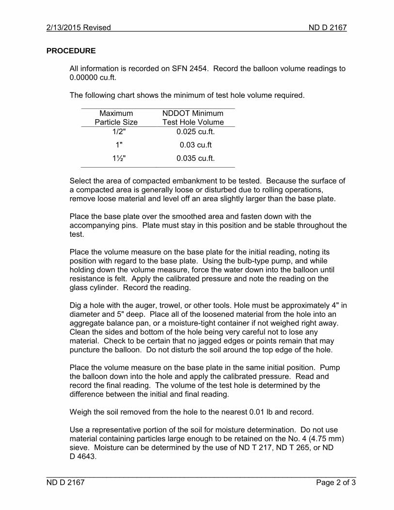
2/13/2015 Revised ND D 2167
________________________________________________________________________ ND D 2167 Page 2 of 3
PROCEDURE
All information is recorded on SFN 2454. Record the balloon volume readings to 0.00000 cu.ft.
The following chart shows the minimum of test hole volume required.
Maximum
Particle Size NDDOT Minimum Test Hole Volume
1/2"
1"
1½"
0.025 cu.ft.
0.03 cu.ft
0.035 cu.ft.
Select the area of compacted embankment to be tested. Because the surface of a compacted area is generally loose or disturbed due to rolling operations, remove loose material and level off an area slightly larger than the base plate.
Place the base plate over the smoothed area and fasten down with the accompanying pins. Plate must stay in this position and be stable throughout the test.
Place the volume measure on the base plate for the initial reading, noting its position with regard to the base plate. Using the bulb-type pump, and while holding down the volume measure, force the water down into the balloon until resistance is felt. Apply the calibrated pressure and note the reading on the glass cylinder. Record the reading.
Dig a hole with the auger, trowel, or other tools. Hole must be approximately 4" in diameter and 5" deep. Place all of the loosened material from the hole into an aggregate balance pan, or a moisture-tight container if not weighed right away. Clean the sides and bottom of the hole being very careful not to lose any material. Check to be certain that no jagged edges or points remain that may puncture the balloon. Do not disturb the soil around the top edge of the hole.
Place the volume measure on the base plate in the same initial position. Pump the balloon down into the hole and apply the calibrated pressure. Read and record the final reading. The volume of the test hole is determined by the difference between the initial and final reading.
Weigh the soil removed from the hole to the nearest 0.01 lb and record.
Use a representative portion of the soil for moisture determination. Do not use material containing particles large enough to be retained on the No. 4 (4.75 mm) sieve. Moisture can be determined by the use of ND T 217, ND T 265, or ND D 4643.
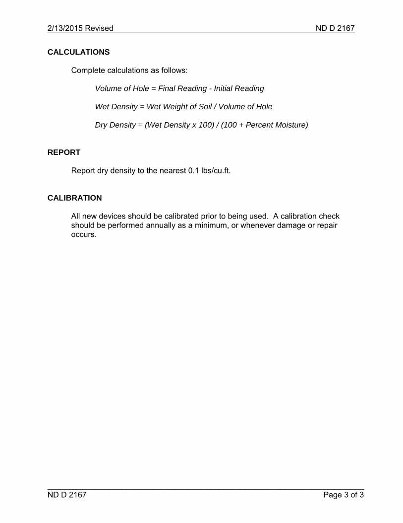
2/13/2015 Revised ND D 2167
________________________________________________________________________ ND D 2167 Page 3 of 3
CALCULATIONS Complete calculations as follows: Volume of Hole = Final Reading - Initial Reading Wet Density = Wet Weight of Soil / Volume of Hole Dry Density = (Wet Density x 100) / (100 + Percent Moisture) REPORT Report dry density to the nearest 0.1 lbs/cu.ft. CALIBRATION All new devices should be calibrated prior to being used. A calibration check
should be performed annually as a minimum, or whenever damage or repair occurs.

Intentionally Left Blank

2/13/2015 Revised ND D 4643
___________________________________________________________________ ND D 4643 Page 1 of 2
ND D 4643 - MICROWAVE METHOD OF DRYING SOILS
Conduct this procedure according to ND D 4643. Consult the current edition of ASTM for procedure in its entirety and equipment specification details.
SCOPE This procedure is used to determine the total moisture content of a soil. The soil is dried to remove all free moisture. This test measures the weight of the moisture removed from the soil.
APPARATUS Balance, readable to 0.1 g Microwave safe dish Glass rod, spatula or knife Oven mitts Heat sink Microwave oven (It is preferable the microwave oven has a vented chamber, and a power rating of about 700 watts with variable power control.
PROCEDURE Record all weights to the nearest 0.1 g. Weigh a clean and dry microwave safe dish and record the weight as tare weight. Determine the sample size needed from the table below. Place the sample in the container and immediately weigh. Record this weight as wet weight.
Sieve Retaining Not More Than About 10% of Sample
Recommended Mass of Moist Specimen
No. 10 (2.0 mm) 100 to 200 g
No. 4 (4.75 mm) 300 to 500 g
3/4" (19 mm) 500 to 1000 g Place the container in the microwave oven with a heat sink, set power to defrost setting, set timer for 3 minutes and start (See Notes). The 3-minute initial time is a minimum. When the microwave oven stops, remove from the oven and weigh to the nearest 0.1 g and note. Use a small spatula, glass rod, or knife and carefully mix the soil. Take care not to lose any soil.

2/13/2015 Revised ND D 4643
___________________________________________________________________ ND D 4643 Page 2 of 2
Return the container and soil to the oven and reheat for 1 minute. Remove, weigh, and again mix with spatula, glass rod, or knife. Repeat this process until a constant weight has been achieved. Use the final weight to calculate the moisture content. Record this weight as dry weight. Discard sample after test.
CALCULATIONS Calculate the percent moisture as follows: A = [(B – C)/(C – D)] x 100 A = Percent moisture B = Mass of original (wet) sample, and container C = Mass of dry sample, and container D = Mass of container
REPORT Report moisture to the nearest 0.1%.
NOTES Initial power setting may be higher than defrost. The proper power setting can be determined only through the use of, and experience with a particular microwave. Soils that are high in moisture and contain a large portion of clay take a longer time to dry. Initial heating time for this type of soil may be 12 minutes. Care should be taken to reduce cohesive samples to 1/4" particles to speed drying and prevent crusting or overheating of the surface while drying the interior. Constant weight is defined as when further drying will cause less than 0.1% additional loss in mass when weighed at specified intervals. Specified weighing interval for microwave drying is one minute.
CALIBRATION A calibration check of the equipment should be performed annually as a minimum, or whenever damage or repair occurs.

2/13/2015 Revised ND D 4791
___________________________________________________________________ ND D 4791 Page 1 of 2
ND D 4791 – FLAT PARTICLES, ELONGATED PARTICLES, OR FLAT AND ELONGATED PARTICLES IN COARSE AGGREGATE
Conduct this procedure according to ND D 4791.
Consult the current edition of ASTM for procedure in its entirety and equipment specification details.
SCOPE
The test method covers the determination of the percentages of flat particles, elongated particles, or flat and elongated particles in coarse aggregate.
REFERENCED DOCUMENTS
ND T 2 and AASHTO T 2, Sampling of Aggregates ND T 27 and AASHTO T 27, Sieve Analysis of Fine and Coarse Aggregate ND T 248 and AASHTO T 248, Reducing Samples of Aggregate to Testing Size ND T 255 and AASHTO T 255, Total Evaporable Moisture Content of Aggregate by Drying ASTM D 4791, Flat Particles, Elongated Particles, or Flat and Elongated Particles in Coarse Aggregate
APPARATUS
Balance Pan Proportional Caliper Device
Oven Sieves: 1½"(37.5 mm), 1"(25.0 mm), ¾"(19.0 mm), ½"(12.5 mm), ⅜"(9.5 mm)
TEST SPECIMEN
Obtain sample according to ND T 2. Thoroughly mix and reduce according to ND T 248. The following table helps determine the initial sample size needed.
Nominal Maximum Size Sample Size
3/8" (9.5 mm) 2 lbs (1 kg)
1/2" (12.5 mm) 4 lbs (2 kg)
3/4" (19.0 mm) 11 lbs (5 kg)
1" (25.0 mm) 22 lbs (10 kg)
1½" (37.5 mm) 33 lbs (15 kg)

2/13/2015 Revised ND D 4791
___________________________________________________________________ ND D 4791 Page 2 of 2
PROCEDURE
Record the information on SFN 51700. All weights are recorded to the nearest 0.1 g. Dry the sample according to ND T 255 at a temperature of 230 ± 9°F (110 ± 5°C). Weigh and record as weight of total sample. Run a dry sieve analysis according to ND T 27. Discard material passing the 3/8" (9.5 mm) sieve. For each size sieve with at least 10% retained, reduce the sample according to ND T 248 until about 100 particles remain. Weigh and record.
If a sieve has less than 10% retained, do not test it.
Use the 5:1 setting on the proportional caliper device. Use the longest dimension of the particle to set the large gap on the device. Tighten the lever. If the particle can fit through the small gap, it is flat or elongated. Set aside all flat or elongated particles from each individual sieve size. Weigh and record each portion after the entire sample has been tested.
CALCULATIONS
To calculate for a single sieve, divide the weight of particles determined to be flat and elongated by the weight of the 100 particles then multiply the result by 100. The equation is as follows:
A = (B/C) x 100 A = Percent flat and elongated particles B = Weight of flat and elongated material C = Total weight of sample on sieve
If a sieve has less than 10% retained, use the value for the next size larger or smaller sieve that retained 10%. If both a larger and smaller size retained 10%, use the average. Refer to SFN 51700 for remainder of calculations.
REPORT
Report the results of flat or elongated particles to the nearest whole percent. CALIBRATION A calibration check of the equipment should be performed annually as a
minimum, or whenever damage or repair occurs.

NDDOT 1
______________________________________________________________________________3/13/2019 Revised NDDOT 1 Page 1 of 2
NDDOT 1 - SAMPLING OF BITUMINOUS MATERIALS SCOPE Conduct these procedures according to NDDOT defined standards.
The following sampling and testing procedures are for emulsified asphalt, performance graded asphalt cement, asphalt cutbacks, and hot applied crack and joint sealants.
REFERENCED DOCUMENTS AASHTO M 81, Cutback Asphalt (Rapid-Curing Type) AASHTO M 82, Cutback Asphalt (Medium-Curing Type) AASHTO M 140 Emulsified Asphalt AASHTO M 208, Cationic Emulsified Asphalt AASHTO M 316, Polymer-Modified Cationic Emulsified Asphalt
AASHTO M 320, Performance-Graded Asphalt Binder AASHTO M 324, Joint and Crack Sealants, Hot Applied, for Concrete and Asphalt Pavement
APPARATUS
- One-half gallon plastic, wide-mouth jar with a plastic cap with liner for emulsions. - Metal quart screw-top containers for performance graded asphalt cement and
cutbacks. - Manufacturer’s original unopened container, either two 30-lb single sample boxes
or one 55-lb double sample box for hot applied crack and joint sealants. PROCEDURE
The sample will be taken from a sampling valve. The valve may be located on the truck or on a discharge line connected to the truck. For emulsions, performance graded asphalt cement, and cutbacks, draw a minimum of one gallon and discard before obtaining the sample.
Engineer will label each sample with the following information: - Project Number - PCN Number - Date sampled - Field sample number - Manifest number

NDDOT 1
______________________________________________________________________________3/13/2019 Revised NDDOT 1 Page 2 of 2
- Manufacturer - Type and grade of bituminous material - Original or check sample - For emulsions, mark first or second half of project.
EMULSIFIED ASPHALT: A sample is defined as two one-half gallon plastic containers. The emulsion containers shall be filled to near capacity, squeeze to expel all air and seal. Sample each truck load delivered to the project.
Record the sample numbers on SFN 10084.
PERFORMANCE GRADED ASPHALT CEMENT:
A sample is defined as two one-quart metal, screw top containers. Randomly obtain one sample for every 250 tons for each grade of asphalt cement. Record the sample number on SFN 5650.
ASPHALT CUTBACKS:
A sample is defined as two one-quart metal, screw top containers filled with the material to be tested. Sample each truck load delivered to the project. Record the sample numbers on SFN 10084.
HOT APPLIED CRACK AND JOINT SEALANT:
All hot applied crack and joint sealers must be submitted in the manufacturer’s original unopened container. Obtain a sample from each lot of crack and joint sealer delivered to the project. Record the sample numbers on SFN 19907.

2/13/2015 Revised NDDOT 3
___________________________________________________________________ NDDOT 3 Page 1 of 2
NDDOT 3 – SHALE, IRON OXIDE PARTICLES, LIGNITE AND OTHER COAL, SOFT PARTICLES, THIN OR ELONGATED PIECES
Conduct this procedure according to NDDOT defined standards. SCOPE
This test method determines the amount of deleterious material retained on the No. 4 sieve. Deleterious material may be shale, hard iron oxide particles, lignite and other coal, and thin or elongated pieces.
REFERENCED PROCEDURES
ND T 2 and AASHTO T 2, Sampling Aggregates ND T 248 and AASHTO T 248, Reducing Samples of Aggregate to Testing Size
ND T 255 and AASHTO T 255, Total Evaporable Moisture Content of Aggregate by Drying
APPARATUS Balance Sieves: 3/8"(9.5 mm) and No. 4 (4.75 mm) Pans Ball pin hammer Plate Oven TEST SPECIMEN
Obtain sample according to ND T 2. Split sample according to ND T 248. Test specimen shall be a representative sample of approximately 2500 g.
PROCEDURE
Record the information on SFN 2455. All weights are recorded to the nearest 0.1 g. Wash and dry the sample according to ND T 255 at a temperature of 230 ± 9°F (110 ± 5°C). Material obtained in conjunction with other test procedures that has already been washed and dried may be used.
Stack the 3/8" and No. 4 sieves on a pan.

2/13/2015 Revised NDDOT 3
___________________________________________________________________ NDDOT 3 Page 2 of 2
Place the sample in the stack of sieves and shake with the mechanical shaker until not more than 0.5% by weight of the total sample passes any sieve during one minute. Approximately 10 minutes will be sufficient for most materials.
Remove material retained on the 3/8" and No. 4 sieves and combine into one pan. Weigh and record as weight of Plus No. 4 fraction. Material passing the No. 4 sieve can be discarded.
Hand pick the shale, hard iron oxide particles, lignite and other coal, and thin or elongated pieces and place in separate pans. Weigh each pan and record. Check the remainder of the sample for soft particles. To determine if particles are soft, use a small 4 oz. ball pin hammer and a flat, non-deflecting plate. Take the hammer and strike each particle with a minimum amount of effort to see if it cracks on impact. A drop of 4" to 5" is sufficient. Place cracked material in container and weigh and record.
CALCULATIONS
Calculate the percentages of handpicked deleterious material by dividing that weight by the weight of the Plus No. 4 fraction and multiplying by 100. The equation is as follows:
A = (B/C) x 100
A = Percent deleterious material B = Combined handpicked portions C = Weight of Plus No. 4 fraction
REPORT Report the results to the nearest 0.1%. NOTES The 3/8" sieve is used to prevent overloading on the No. 4 sieve. Thin or elongated pieces are defined as having a maximum thickness less than
1/4 the maximum width, or maximum length more than three times the maximum width.
CALIBRATION A calibration check of the equipment should be performed annually as a
minimum, or whenever damage or repair occurs.

2/13/2015 Revised NDDOT 4
___________________________________________________________________ NDDOT 4 Page 1 of 2
NDDOT 4 - PERCENTAGE OF FRACTURED PARTICLES IN COARSE AGGREGATE
Conduct this procedure according to NDDOT defined standards. SCOPE
This procedure determines the percentage of particles, which by visual inspection have a fractured face. A fractured face is an area that is at least 25% of the largest cross section of the particle.
REFERENCED PROCEDURES
ND T 2 and AASHTO T 2, Sampling Aggregates ND T 248 and AASHTO T 248, Reduce Samples of Aggregate to Testing Size ND T 255 and AASHTO T 255, Total Evaporable Moisture Content of Aggregate by Drying
APPARATUS Balance No. 4 sieve Spatula Pan Oven TEST SPECIMEN
Obtain a sample according to ND T 2. Reduce the sample according to ND T 248. Final sample size needed is approximately 500 g. Wash and dry according to ND T 255 at a temperature of 230 ± 9°F (110 ± 5°C). Sieve the sample over a No. 4 sieve. Test only material retained on the No. 4 sieve. This is considered the weight of the total sample. Discard the material that passes the No. 4 sieve.

2/13/2015 Revised NDDOT 4
___________________________________________________________________ NDDOT 4 Page 2 of 2
PROCEDURE Record all information on SFN 9987. All weights are recorded to the nearest
0.1 g. Spread the sample on a clean flat surface large enough to permit the material
to be spread thinly for careful inspection. Use the spatula or similar tool to separate the material into three separate portions:
1. Fractured particles. 2. Questionable fractured particles. 3. Particles with no fractured faces.
The requirement of the fracture is dependent on the class of aggregate and the particles will have either one or two fractured faces.
Place each portion into individual pans. Weigh and record each portion.
CALCULATIONS
Percentage of particles with fractured faces is calculated according to the following formula:
Fractured Faces = [WF + (WQ/2)] / WA x 100 WF = Weight of fractured particles WQ = Weight of questionable fractured particles WA = Weight of total sample REPORT Report the percentage of particles with fractured faces to the nearest 1%. NOTES
A fractured face may be natural or caused by a mechanical process. CALIBRATION A calibration check of the equipment should be performed annually as a
minimum, or whenever damage or repair occurs.

NDDOT 5
____________________________________________________________________ 3/13/2019 Revised NDDOT 5 Page 1 of 2
NDDOT 5 - SAMPLING AND SPLITTING FIELD VERIFICATION HOT MIX ASPHALT (HMA) SAMPLES
SCOPE Conduct this procedure according to NDDOT defined standards. This procedure is used to obtain samples of hot mix asphalt from a windrow in
front of the paver or from the mat behind the paver. The material is then used to run ND T 209 or ND T 312.
REFERENCED DOCUMENTS
ND T 209, Theoretical Maximum Specific Gravity and Density of Hot Mix Asphalt ND T 312, Preparing and Determining the Density of Hot Mix Asphalt (HMA) Specimens by Means of the Superpave Gyratory Compactor
APPARATUS Shovel - flat bottom, square-edge Pails Insulated container Scoop - flat bottom, square-edge Trowel PROCEDURE
Two methods are allowed for obtaining samples. From a windrow in front of the paver or from the mat behind the paver.
SAMPLE: Sample size shall be large enough to conduct the required testing. The Engineer will randomly select the time and location.
For the Contractor’s Quality Control (QC) testing, the sample taken is split in half with the Engineer obtaining possession of one half of the sample. For Quality Assurance (QA) and Independent Assurance (IA), a sample will be taken by the Contractor under the observation of the Engineer. The Engineer will transport all QA and IA samples to the lab.

NDDOT 5
____________________________________________________________________ 3/13/2019 Revised NDDOT 5 Page 2 of 2
SAMPLING FROM A WINDROW: Choose a location along the windrow that appears uniform and contains material from one transport truck. Avoid the beginning or the end of the windrow section. A sample is a composite of three locations from the windrow. Use a shovel to remove approximately one foot of material from the top of the windrow, discarding the material to either side. Take sample from the flattened area of the windrow. Be careful to avoid including material from the subgrade or base. Place the sample in the pails. Place the pails in an insulated container and cover to retain as much heat as possible for the transport to the lab.
SAMPLING FROM THE MAT BEHIND THE PAVER: Take one bucket full of material from the asphalt windrow in front of the paver.
This material will be used to fill the hole created when obtaining the sample from behind the paver.
Mark out an area that is large enough to provide the required size sample. Use
the shovel and take the sample a minimum of one foot from the edge of the pavement. Be careful to avoid including material from the subgrade or base.
Place the sample in the pails. Place the pails in an insulated container and cover
to retain as much heat as possible for the transport to the lab. SPLITTING:
At the lab place the entire sample on a non-absorbent level surface or in a pan
and re-mix with the scoop. Carefully flatten to a uniform thickness and divide the flattened mass into four equal quarters using a trowel.
Use one quarter for ND T 209 and the opposite quarter for ND T 312. A second
gyratory specimen can be made from the last remaining quarters. Place any unused portion of the hot mix asphalt sample into a container and save it for further testing if needed.
Discard the unused portion when all testing on the original sample is complete.

2/13/2015 Revised NDDOT 6
NDDOT 6 Page 1 of 1
NDDOT 6 - SETTLEMENT TEST FOR LIQUID MEMBRANE CURING COMPOUND
Conduct these procedures according to NDDOT defined standards. SCOPE
This procedure determines the amount of settlement in a liquid membrane curing compound.
APPARATUS 100 mL graduated cylinder with graduation intervals of 1 mL Disposable pipette Rubber stopper TEST SPECIMEN
Obtain one pint of curing compound. PROCEDURE Bring the sample to room temperature and mix until curing compound is
homogeneous. Pour curing compound into a 100 mL graduated cylinder. Using a disposable
pipette, remove any air bubbles incorporated in the curing compound. At this time add or remove curing compound so the bottom of the meniscus reaches the 100 mL mark.
Secure a rubber stopper in the graduated cylinder to minimize evaporation and
leave the sample undisturbed for 72 ± 1 hours. At the end of 72 ± 1 hours, measure the amount of settling to the nearest mL. The degree of settling is the amount of clear, colorless supernatant liquid in the graduated cylinder.
REPORT Report the settlement to the nearest mL.

Intentionally Left Blank

FIELD SAMPLING AND TESTING MANUAL
ROUNDING PROCEDURES
FOR DETERMINING SIGNIFICANT DIGITS

Intentionally Left Blank

Rounding Numbers
____________________________________________________________________________________ 1
ROUNDING NUMBERS FOR DETERMINING SIGNIFICANT DIGITS
It is necessary to perform all mathematical calculations in the proper format. The industry references The American Society for Testing Materials (ASTM) Standard E-29, “Practice for Using Significant Digits in Test Data to Determine Conformance with Specifications.”
ROUNDING OFF RULES
A. When the figure next beyond the last place to be retained is less than 5, retain unchanged the figure in the last place retained.
Example: Round to the nearest tenth (0.1) 45.71 = 45.7
45.72 = 45.7 45.73 = 45.7 45.74 = 45.7
B. When the figure next beyond the last place to be retained is greater than 5, increase by 1 the figure in the last place retained.
Example: Round to the nearest tenth (0.1) 45.76 = 45.8
45.77 = 45.8 45.78 = 45.8 45.79 = 45.8
C. When the next figure beyond the last place to be retained is 5 and there are no figures beyond this 5, or only zeros, increase the figure to be retained by 1 if it is odd.
Example: Round to the nearest tenth (0.1) 45.7500 = 45.8
Leave the figure unchanged if it is even.
Example: Round to the nearest tenth (0.1) 45.4500 = 45.4
Increase the figure by 1 in the last place retained, if there are figures beyond this 5.
Example: Round to the nearest tenth (0.1) 45.45001 = 45.5
Round to the nearest tenth (0.1) 45.45105 = 45.5 Round to the nearest tenth (0.1) 45.45099 = 45.5
COMPUTER AND CALCULATOR ROUNDING (unofficial rounding)
Today's computers and calculators provide automatic rounding. However, in the case of part “C” above, they simply round up.

Rounding Numbers
____________________________________________________________________________________ 2
When using hand held calculators, many people carry all of the decimals, beyond significant figures, when making several related computations. This is not the correct method to perform computations; however, it does save time. You may choose to carry the decimals through long computations however, if the computation results in a value that is near a specification limit, the computation must be recalculated using the methods described below. The methods described below are the official round-off procedures of the NDDOT.
GENERAL PROCEDURES FOR ROUNDING
Primary calculations are carried out and rounded to one decimal place more than is needed in the final answers.
When adding: Primary calculations are carried out - rounded to hundredths (0.01)
510.37 cu. yds. 270.12 cu. yds. +121.89 cu. yds. 902.38 cu. yds. = Total cubic yards of riprap placed. 902.4 cu. yds. = Final answers are rounded to tenths (0.1).
When using a calculation where rounding cannot be set, expect some differences in the answers. Do not carry calculations to decimal places beyond those needed.
Calculating to tenths (0.1):
When tenths are required, primary calculations are carried out and rounded to hundredths (0.01). Final answers are rounded to tenths (0.1).
When multiplying: Primary – Calculation A Primary – Calculation B 25.52 x 13.14 = 335.3328 9.45 x 3.2 = 30.240 Rounded to: 335.33 Rounded to: 30.24
Final Calculation
335.33 X 30.24 = 10,140.3792 Rounded to: 10,140.4
Calculating to hundredths (0.01):
When hundredths are required, primary calculations are carried out and rounded to thousandths (0.001). Final answers are rounded to hundredths (0.01).

Rounding Numbers
____________________________________________________________________________________ 3
When dividing: Primary – Calculation A Primary – Calculation B 542.15 ÷ 28.47 =19.0428 138.46 ÷ 12.12 = 11.4241 Rounded to: 19.043 Rounded to: 11.424
Final Calculation
19.043 ÷ 11.424 = 1.667 Rounded to: 1.67
Calculating to thousandths (0.001):
When thousandths are required, primary calculations are carried out and rounded to ten thousandths (0.0001). Final answers are rounded to thousandths (0.001).
When adding: Primary – Calculation A Primary – Calculation B
4.46891 3.97163 2.15672 1.05872 1.12013 2.18291
+ 0.01882 + 1.50562 7.76458 8.71888
Rounded to: 7.7646 Rounded to: 8.7189
Final Calculation 7.7646
+8.7189 16.4835
Rounded to: 16.484 Rounding final answers to whole units:
Always round the numbers you have to work with to one more decimal place than needed in the final answer. If the final answer is to be in tenths (0.1), round the numbers to hundredths (0.01). If the final answer is to be in hundredths (0.01), round the number to thousandths (0.001). If the final answer is to be to the nearest whole number, round the numbers to tenths (0.1).

Rounding Numbers
____________________________________________________________________________________ 4
The following values will be added to find an answer to the nearest whole number:
460.57 cu. yds. 460.6 cu. yds. 571.59 cu. yds. 571.6 cu. yds.
+342.65 cu. yds. +342.7 cu. yds. 1374.9 cu. yds. 1375 cu. yds.
Note how the numbers are rounded to tenths before they are added and how the final answer is rounded to a whole number.
One more rule: In calculations using Pi (3.1416), the first calculation is made without rounding. In other words, the number 3.1416 is not rounded, but the first calculation using 3.1416 is rounded.
TECHNICAL DESCRIPTION OF ROUND-OFF RULE
Discard the (k + 1)th and all subsequent decimals.
(a) If the number thus discarded is less than half a unit in the kth place, leave the kth decimal unchanged ("rounding down").
(b) If it is greater than half a unit in the kth place, add one to the kth decimal ("rounding up").
(c) If it is exactly half a unit, round off to the nearest even decimal (example: rounding off 3.45 and 3.55 to one decimal gives 3.4 and 3.6, respectively).
The last part of the rule is supposed to ensure that in discarding exactly half a decimal, rounding up and rounding down happens about equally often, on the average.
If we round off 1.2535 to 3, 2, 1 decimals, we get 1.254, 1.25, 1.3, but if 1.25 is rounded off to one decimal, without further information we get 1.2.
For further or additional determinations, refer to ASTM E-29, “Practice for Using Significant Digits in Test Data to Determine Conformance with Specifications.”

FIELD SAMPLING AND TESTING MANUAL
RANDOM SAMPLING AND TESTING PROCEDURES

Intentionally Left Blank

Random Sampling
RANDOM SAMPLING AND TESTING
A random sample is a sample taken by the use of a sampling plan in which each unit of a lot has an equal chance of being chosen. Random sampling is based on the use of a random number table to select items such as test sites, test samples, and times for selection of samples. The random number table provides the mean by which an item can be selected using the product of the random number and the dimension of the applicable item. The use of a calculator to generate random numbers is acceptable, but in the following examples the random number table will be used.
Example No. 1
Assume one day's production is a lot. The contractor begins work at 7:00 A.M. and works a 12-hour day. The sampling frequency is four samples selected at random times during the day.
Divide the 12-hour day into four equal sublots of three hours each. The following times result:
7:00 A.M. - 10:00 A.M. 10:00 A.M. - 1:00 P.M. 1:00 P.M. - 4:00 P.M. 4:00 P.M. - 7:00 P.M.
To determine the sampling times, arbitrarily select a group of digits on the random numbers table (located at the back of this appendix) by placing the point of a pencil on the page with eyes closed. In addition to the number under the pencil point, select three more numbers by going up or down, left or right, or diagonally. The pencil point landed on 0.18 in this example. Prior to the selection of the number it had been decided to go down the column. The three additional numbers are 0.90, 0.93, and 0.73 (Block “A”). Multiply each number by three hours (convert to 180 minutes) and add the result to the beginning time of each sublot to determine the sample times.
0.18 x 180 minutes = 32 minutes 0.90 x 180 minutes = 162 minutes 0.93 x 180 minutes = 167 minutes 0.73 x 180 minutes = 131 minutes
Samples should be obtained at the following times:
32 minutes after 7:00 A.M. or 7:32 A.M. 162 minutes after 10:00 A.M. or 12:42 P.M. 167 minutes after 1:00 P.M. or 3:47 P.M. 131 minutes after 4:00 P.M. or 6:11 P.M.
_____________________________________________________________________ 1

Random Sampling
Example No. 2
Under Section 408 of the Standard Specifications, the Contractor is to take two cores in each sublot for determining density. The cores are to be taken adjacent to each other and at a random location. A sublot is defined as one paver-width wide (excluding the shoulders), 2,000 ft long, and of the depth specified for the pavement course.
Sample numbers and sublot numbers are established for the full day's production. On SFN 10071, “Compaction Control,” record the sample number and the beginning station of the lot. The beginning station of each sublot is 2,000 ft greater than the previous one. Compute the locations to be cored using random numbers to determine the station and offset from the edge of the pavement. Adjust core locations falling within one foot of the pavement edge or select a new random location within the test area.
Use the same procedure as in Example No. 1 to arbitrarily select the digits from the random number table. In this example only three numbers will be chosen (Block “B”). Assume the beginning station of the lot to be 105+00.
Sample No. Station
1 0.13 x 2000 = 260 ft Sta. 105+00 + 260 = Sta. 107+60 2 0.94 x 2000 = 1880 ft Sta. 125+00 + 1880 = Sta. 143+80 3 0.14 x 2000 = 280 ft Sta. 145+00 + 280 = Sta. 147+80
To select the transverse distance from the right edge of the roadway, three additional consecutive numbers are chosen following the procedure in Example No. 1. Each of the digits in Block "C" is multiplied by the lane width (12 ft).
Sample No. Transverse Distance from Right Edge
1 0.68 x 12 = 8.2 ft 2 0.26 x 12 = 3.1 ft 3 0.85 x 12 = 10.2 ft
The calculations above result in the following sampling schedule for each sublot:
Sample No. Sample Location
1 Sta. 107+60 - 8.2 ft from right edge of roadway 2 Sta. 143+80 - 3.1 ft from right edge of roadway 3 Sta. 147+80 - 10.2 ft from right edge of roadway
_____________________________________________________________________ 2

Random Sampling
________________________________________________________________________________ 3
TABLE OF RANDOM NUMBERS WITH EXAMPLES
0.10 0.09 0.73 0.25 0.33 0.76 0.52 0.01 0.35 0.86 0.34 0.67 0.35 0.48 0.76 0.80 0.95 0.90 0.91 0.17 0.37 0.54 0.20 0.48 0.05 0.64 0.89 0.47 0.42 0.96 0.24 0.80 0.52 0.40 0.37 0.20 0.63 0.61 0.04 0.02 0.08 0.42 0.26 0.89 0.53 0.19 0.64 0.50 0.93 0.03 0.23 0.20 0.90 0.25 0.60 0.15 0.95 0.33 0.47 0.64 0.99 0.01 0.90 0.25 0.29 0.09 0.37 0.67 0.07 0.15 0.38 0.31 0.13 0.11 0.65 0.88 0.67 0.67 0.43 0.97 0.12 0.80 0.79 0.99 0.70 0.80 0.15 0.73 0.61 0.47 0.64 0.03 0.23 0.66 0.53 0.98 0.95 0.11 0.68 0.77
0.66 0.06 0.57 0.47 0.17 0.34 0.07 0.27 0.68 0.50 0.36 0.69 0.73 0.61 0.70 0.65 0.81 0.33 0.98 0.85 0.31 0.06 0.01 0.08 0.05 0.45 0.57 0.18 0.24 0.06 0.35 0.30 0.34 0.26 0.14 0.86 0.79 0.90 0.74 0.39 0.85 0.26 0.97 0.76 0.02 0.02 0.05 0.16 0.56 0.92 0.68 0.66 0.57 0.48 0.18 0.73 0.05 0.38 0.52 0.47 0.63 0.57 0.33 0.21 0.35 0.05 0.32 0.54 0.70 0.48 0.90 0.55 0.35 0.75 0.48 0.28 0.46 0.82 0.87 0.09 0.73 0.79 0.64 0.57 0.53 0.03 0.52 0.96 0.47 0.78 0.35 0.80 0.83 0.42 0.82 0.60 0.93 0.52 0.03 0.44
A 0.98 0.52 0.01 0.77 0.67 0.14 0.90 0.56 0.86 0.07 0.22 0.10 0.94 0.05 0.58 0.60 0.97 0.09 0.34 0.33 0.11 0.80 0.50 0.54 0.31 0.39 0.80 0.82 0.77 0.32 0.50 0.72 0.56 0.82 0.48 0.29 0.40 0.52 0.42 0.01 0.83 0.45 0.29 0.96 0.34 0.06 0.28 0.89 0.80 0.83 0.13 0.74 0.67 0.00 0.78 0.18 0.47 0.54 0.06 0.10 0.88 0.68 0.54 0.02 0.00 0.86 0.50 0.75 0.84 0.01 0.36 0.76 0.66 0.79 0.51 0.90 0.36 0.47 0.64 0.93 0.99 0.59 0.46 0.73 0.48 0.87 0.51 0.76 0.49 0.69 0.91 0.82 0.60 0.89 0.28 0.93 0.78 0.56 0.13 0.68
0.65 0.48 0.11 0.76 0.74 0.17 0.46 0.85 0.09 0.50 0.58 0.04 0.77 0.69 0.74 0.73 0.03 0.95 0.71 0.86 0.80 0.12 0.43 0.56 0.35 0.17 0.72 0.70 0.80 0.15 0.45 0.31 0.82 0.23 0.74 0.21 0.11 0.57 0.82 0.53 0.74 0.35 0.09 0.98 0.17 0.77 0.40 0.27 0.72 0.14 0.43 0.23 0.60 0.02 0.10 0.45 0.52 0.16 0.42 0.37 0.69 0.91 0.62 0.68 0.03 0.66 0.25 0.22 0.91 0.48 0.36 0.93 0.68 0.72 0.03 0.76 0.62 0.11 0.39 0.90 0.09 0.89 0.32 0.05 0.05 0.14 0.22 0.56 0.85 0.14 0.46 0.42 0.75 0.67 0.88 0.96 0.29 0.77 0.88 0.22
C 0.91 0.49 0.91 0.45 0.23 0.68 0.47 0.92 0.76 0.86 0.46 0.16 0.28 0.35 0.54 0.94 0.75 0.08 0.99 0.23 0.80 0.33 0.69 0.45 0.98 0.26 0.94 0.03 0.68 0.58 0.70 0.29 0.73 0.41 0.35 0.53 0.14 0.03 0.33 0.40 0.44 0.10 0.48 0.19 0.49 0.85 0.15 0.74 0.79 0.54 0.32 0.97 0.92 0.65 0.75 0.57 0.60 0.04 0.08 0.81 0.12 0.55 0.07 0.37 0.42 0.11 0.10 0.00 0.20 0.40 0.12 0.86 0.07 0.46 0.97 0.96 0.64 0.48 0.94 0.39 0.63 0.60 0.64 0.93 0.29 0.16 0.50 0.53 0.44 0.84 0.40 0.21 0.95 0.25 0.63 0.43 0.65 0.17 0.70 0.82
0.61 0.19 0.69 0.04 0.46 0.26 0.45 0.74 0.77 0.74 0.51 0.92 0.43 0.37 0.29 0.65 0.39 0.45 0.95 0.93 0.15 0.47 0.44 0.52 0.66 0.95 0.27 0.07 0.99 0.53 0.59 0.36 0.78 0.38 0.48 0.82 0.39 0.61 0.01 0.18 0.94 0.55 0.72 0.85 0.73 0.67 0.89 0.75 0.43 0.87 0.54 0.62 0.24 0.44 0.31 0.91 0.19 0.04 0.25 0.92 0.42 0.48 0.11 0.62 0.13 0.97 0.34 0.40 0.87 0.21 0.16 0.86 0.84 0.87 0.67 0.03 0.07 0.11 0.20 0.59 0.23 0.52 0.37 0.83 0.17 0.73 0.20 0.88 0.98 0.37 0.68 0.93 0.59 0.14 0.16 0.26 0.25 0.22 0.96 0.63
B 0.04 0.49 0.35 0.24 0.94 0.75 0.24 0.63 0.38 0.24 0.45 0.86 0.25 0.10 0.25 0.61 0.96 0.27 0.93 0.35 0.00 0.54 0.99 0.76 0.54 0.64 0.05 0.18 0.81 0.59 0.96 0.11 0.96 0.38 0.96 0.54 0.69 0.28 0.23 0.91 0.35 0.96 0.31 0.53 0.07 0.26 0.89 0.80 0.93 0.54 0.33 0.35 0.13 0.54 0.62 0.77 0.97 0.45 0.00 0.24 0.59 0.80 0.80 0.83 0.91 0.45 0.42 0.72 0.68 0.42 0.83 0.60 0.94 0.97 0.00 0.13 0.02 0.12 0.48 0.92 0.46 0.05 0.88 0.52 0.36 0.01 0.39 0.00 0.22 0.86 0.77 0.28 0.14 0.40 0.77 0.93 0.91 0.08 0.36 0.47
0.32 0.17 0.90 0.05 0.97 0.87 0.37 0.92 0.52 0.41 0.05 0.56 0.70 0.70 0.07 0.86 0.74 0.31 0.71 0.57 0.69 0.23 0.46 0.14 0.06 0.20 0.11 0.74 0.52 0.04 0.15 0.95 0.66 0.00 0.00 0.18 0.74 0.39 0.24 0.23 0.19 0.56 0.54 0.14 0.30 0.01 0.75 0.87 0.53 0.79 0.40 0.41 0.92 0.15 0.85 0.66 0.67 0.43 0.68 0.06 0.45 0.15 0.51 0.49 0.38 0.19 0.47 0.60 0.72 0.46 0.43 0.66 0.79 0.45 0.43 0.59 0.04 0.79 0.00 0.33 0.94 0.86 0.43 0.19 0.94 0.36 0.16 0.81 0.08 0.51 0.34 0.88 0.88 0.15 0.53 0.01 0.54 0.03 0.54 0.56
0.98 0.08 0.62 0.48 0.26 0.45 0.24 0.02 0.84 0.04 0.44 0.99 0.90 0.88 0.96 0.39 0.09 0.47 0.34 0.07 0.33 0.18 0.51 0.62 0.32 0.41 0.94 0.15 0.09 0.49 0.89 0.43 0.54 0.85 0.81 0.88 0.69 0.54 0.19 0.94 0.80 0.95 0.10 0.04 0.06 0.96 0.38 0.27 0.07 0.74 0.20 0.15 0.12 0.33 0.87 0.45 0.01 0.62 0.52 0.98 0.79 0.75 0.24 0.91 0.40 0.71 0.96 0.12 0.82 0.96 0.69 0.86 0.10 0.25 0.91 0.74 0.85 0.22 0.05 0.39 0.18 0.63 0.33 0.25 0.37 0.98 0.14 0.50 0.65 0.71 0.31 0.01 0.02 0.46 0.74 0.05 0.45 0.56 0.14 0.27
0.74 0.02 0.94 0.39 0.02 0.77 0.55 0.73 0.22 0.70 0.97 0.79 0.01 0.71 0.19 0.52 0.52 0.75 0.80 0.21 0.54 0.17 0.84 0.56 0.11 0.80 0.99 0.33 0.71 0.43 0.05 0.33 0.51 0.29 0.69 0.56 0.12 0.71 0.92 0.55 0.11 0.66 0.44 0.98 0.83 0.52 0.07 0.98 0.48 0.27 0.59 0.38 0.17 0.15 0.39 0.09 0.97 0.33 0.34 0.40 0.48 0.32 0.47 0.79 0.28 0.31 0.24 0.96 0.47 0.10 0.02 0.29 0.53 0.68 0.70 0.32 0.30 0.75 0.75 0.46 0.69 0.07 0.49 0.41 0.38 0.87 0.63 0.79 0.19 0.76 0.35 0.58 0.40 0.44 0.01 0.10 0.51 0.82 0.16 0.15

Random Sampling
________________________________________________________________________________ 4
TABLE OF RANDOM NUMBERS
0.10 0.09 0.73 0.25 0.33 0.76 0.52 0.01 0.35 0.86 0.34 0.67 0.35 0.48 0.76 0.80 0.95 0.90 0.91 0.170.37 0.54 0.20 0.48 0.05 0.64 0.89 0.47 0.42 0.96 0.24 0.80 0.52 0.40 0.37 0.20 0.63 0.61 0.04 0.020.08 0.42 0.26 0.89 0.53 0.19 0.64 0.50 0.93 0.03 0.23 0.20 0.90 0.25 0.60 0.15 0.95 0.33 0.47 0.640.99 0.01 0.90 0.25 0.29 0.09 0.37 0.67 0.07 0.15 0.38 0.31 0.13 0.11 0.65 0.88 0.67 0.67 0.43 0.970.12 0.80 0.79 0.99 0.70 0.80 0.15 0.73 0.61 0.47 0.64 0.03 0.23 0.66 0.53 0.98 0.95 0.11 0.68 0.77
0.66 0.06 0.57 0.47 0.17 0.34 0.07 0.27 0.68 0.50 0.36 0.69 0.73 0.61 0.70 0.65 0.81 0.33 0.98 0.850.31 0.06 0.01 0.08 0.05 0.45 0.57 0.18 0.24 0.06 0.35 0.30 0.34 0.26 0.14 0.86 0.79 0.90 0.74 0.390.85 0.26 0.97 0.76 0.02 0.02 0.05 0.16 0.56 0.92 0.68 0.66 0.57 0.48 0.18 0.73 0.05 0.38 0.52 0.470.63 0.57 0.33 0.21 0.35 0.05 0.32 0.54 0.70 0.48 0.90 0.55 0.35 0.75 0.48 0.28 0.46 0.82 0.87 0.090.73 0.79 0.64 0.57 0.53 0.03 0.52 0.96 0.47 0.78 0.35 0.80 0.83 0.42 0.82 0.60 0.93 0.52 0.03 0.44
0.98 0.52 0.01 0.77 0.67 0.14 0.90 0.56 0.86 0.07 0.22 0.10 0.94 0.05 0.58 0.60 0.97 0.09 0.34 0.330.11 0.80 0.50 0.54 0.31 0.39 0.80 0.82 0.77 0.32 0.50 0.72 0.56 0.82 0.48 0.29 0.40 0.52 0.42 0.010.83 0.45 0.29 0.96 0.34 0.06 0.28 0.89 0.80 0.83 0.13 0.74 0.67 0.00 0.78 0.18 0.47 0.54 0.06 0.100.88 0.68 0.54 0.02 0.00 0.86 0.50 0.75 0.84 0.01 0.36 0.76 0.66 0.79 0.51 0.90 0.36 0.47 0.64 0.930.99 0.59 0.46 0.73 0.48 0.87 0.51 0.76 0.49 0.69 0.91 0.82 0.60 0.89 0.28 0.93 0.78 0.56 0.13 0.68
0.65 0.48 0.11 0.76 0.74 0.17 0.46 0.85 0.09 0.50 0.58 0.04 0.77 0.69 0.74 0.73 0.03 0.95 0.71 0.860.80 0.12 0.43 0.56 0.35 0.17 0.72 0.70 0.80 0.15 0.45 0.31 0.82 0.23 0.74 0.21 0.11 0.57 0.82 0.530.74 0.35 0.09 0.98 0.17 0.77 0.40 0.27 0.72 0.14 0.43 0.23 0.60 0.02 0.10 0.45 0.52 0.16 0.42 0.370.69 0.91 0.62 0.68 0.03 0.66 0.25 0.22 0.91 0.48 0.36 0.93 0.68 0.72 0.03 0.76 0.62 0.11 0.39 0.900.09 0.89 0.32 0.05 0.05 0.14 0.22 0.56 0.85 0.14 0.46 0.42 0.75 0.67 0.88 0.96 0.29 0.77 0.88 0.22
0.91 0.49 0.91 0.45 0.23 0.68 0.47 0.92 0.76 0.86 0.46 0.16 0.28 0.35 0.54 0.94 0.75 0.08 0.99 0.230.80 0.33 0.69 0.45 0.98 0.26 0.94 0.03 0.68 0.58 0.70 0.29 0.73 0.41 0.35 0.53 0.14 0.03 0.33 0.400.44 0.10 0.48 0.19 0.49 0.85 0.15 0.74 0.79 0.54 0.32 0.97 0.92 0.65 0.75 0.57 0.60 0.04 0.08 0.810.12 0.55 0.07 0.37 0.42 0.11 0.10 0.00 0.20 0.40 0.12 0.86 0.07 0.46 0.97 0.96 0.64 0.48 0.94 0.390.63 0.60 0.64 0.93 0.29 0.16 0.50 0.53 0.44 0.84 0.40 0.21 0.95 0.25 0.63 0.43 0.65 0.17 0.70 0.82
0.61 0.19 0.69 0.04 0.46 0.26 0.45 0.74 0.77 0.74 0.51 0.92 0.43 0.37 0.29 0.65 0.39 0.45 0.95 0.930.15 0.47 0.44 0.52 0.66 0.95 0.27 0.07 0.99 0.53 0.59 0.36 0.78 0.38 0.48 0.82 0.39 0.61 0.01 0.180.94 0.55 0.72 0.85 0.73 0.67 0.89 0.75 0.43 0.87 0.54 0.62 0.24 0.44 0.31 0.91 0.19 0.04 0.25 0.920.42 0.48 0.11 0.62 0.13 0.97 0.34 0.40 0.87 0.21 0.16 0.86 0.84 0.87 0.67 0.03 0.07 0.11 0.20 0.590.23 0.52 0.37 0.83 0.17 0.73 0.20 0.88 0.98 0.37 0.68 0.93 0.59 0.14 0.16 0.26 0.25 0.22 0.96 0.63
0.04 0.49 0.35 0.24 0.94 0.75 0.24 0.63 0.38 0.24 0.45 0.86 0.25 0.10 0.25 0.61 0.96 0.27 0.93 0.350.00 0.54 0.99 0.76 0.54 0.64 0.05 0.18 0.81 0.59 0.96 0.11 0.96 0.38 0.96 0.54 0.69 0.28 0.23 0.910.35 0.96 0.31 0.53 0.07 0.26 0.89 0.80 0.93 0.54 0.33 0.35 0.13 0.54 0.62 0.77 0.97 0.45 0.00 0.240.59 0.80 0.80 0.83 0.91 0.45 0.42 0.72 0.68 0.42 0.83 0.60 0.94 0.97 0.00 0.13 0.02 0.12 0.48 0.920.46 0.05 0.88 0.52 0.36 0.01 0.39 0.00 0.22 0.86 0.77 0.28 0.14 0.40 0.77 0.93 0.91 0.08 0.36 0.47
0.32 0.17 0.90 0.05 0.97 0.87 0.37 0.92 0.52 0.41 0.05 0.56 0.70 0.70 0.07 0.86 0.74 0.31 0.71 0.570.69 0.23 0.46 0.14 0.06 0.20 0.11 0.74 0.52 0.04 0.15 0.95 0.66 0.00 0.00 0.18 0.74 0.39 0.24 0.230.19 0.56 0.54 0.14 0.30 0.01 0.75 0.87 0.53 0.79 0.40 0.41 0.92 0.15 0.85 0.66 0.67 0.43 0.68 0.060.45 0.15 0.51 0.49 0.38 0.19 0.47 0.60 0.72 0.46 0.43 0.66 0.79 0.45 0.43 0.59 0.04 0.79 0.00 0.330.94 0.86 0.43 0.19 0.94 0.36 0.16 0.81 0.08 0.51 0.34 0.88 0.88 0.15 0.53 0.01 0.54 0.03 0.54 0.56
0.98 0.08 0.62 0.48 0.26 0.45 0.24 0.02 0.84 0.04 0.44 0.99 0.90 0.88 0.96 0.39 0.09 0.47 0.34 0.070.33 0.18 0.51 0.62 0.32 0.41 0.94 0.15 0.09 0.49 0.89 0.43 0.54 0.85 0.81 0.88 0.69 0.54 0.19 0.940.80 0.95 0.10 0.04 0.06 0.96 0.38 0.27 0.07 0.74 0.20 0.15 0.12 0.33 0.87 0.45 0.01 0.62 0.52 0.980.79 0.75 0.24 0.91 0.40 0.71 0.96 0.12 0.82 0.96 0.69 0.86 0.10 0.25 0.91 0.74 0.85 0.22 0.05 0.390.18 0.63 0.33 0.25 0.37 0.98 0.14 0.50 0.65 0.71 0.31 0.01 0.02 0.46 0.74 0.05 0.45 0.56 0.14 0.27
0.74 0.02 0.94 0.39 0.02 0.77 0.55 0.73 0.22 0.70 0.97 0.79 0.01 0.71 0.19 0.52 0.52 0.75 0.80 0.210.54 0.17 0.84 0.56 0.11 0.80 0.99 0.33 0.71 0.43 0.05 0.33 0.51 0.29 0.69 0.56 0.12 0.71 0.92 0.550.11 0.66 0.44 0.98 0.83 0.52 0.07 0.98 0.48 0.27 0.59 0.38 0.17 0.15 0.39 0.09 0.97 0.33 0.34 0.400.48 0.32 0.47 0.79 0.28 0.31 0.24 0.96 0.47 0.10 0.02 0.29 0.53 0.68 0.70 0.32 0.30 0.75 0.75 0.460.69 0.07 0.49 0.41 0.38 0.87 0.63 0.79 0.19 0.76 0.35 0.58 0.40 0.44 0.01 0.10 0.51 0.82 0.16 0.15

Project Number
INSPECTOR'S SIGNATURE
CONTRACTOR BRAND ACGRADE ACCLASS AGGR.
LOT NUMBER DATE PAVEDLANE
AIR VOIDS (H)100 - (F x 100) G
RANDOM NUMBERS SAMPLE LOCATIONBEG. STA.
LENGTH WIDTH
COMPACTION CONTROLNorth Dakota Department of Transportation, Construction ServicesSFN 10071 (Rev. 12-99)
WT. INWATER (B)
WT. INAIR (A)
SAMPLENO.
VOL. (D)(C-B)
SURFACEDRY (C)
BULKS. G. (E)
A/D
MATDENSITY(F)
(Ex62.4)
MAXIMUMTHEORETICALDENSITY (G)STATION OFFSET

Intentionally Left Blank

FIELD SAMPLING AND TESTING MANUAL
QUALITY ASSURANCE PROGRAM
FOR
PRESTRESSED AND PRECAST
CONCRETE PRODUCTS

Intentionally Left Blank

QUALITY ASSURANCE PROGRAM FOR PRESTRESSED AND PRECAST CONCRETE PRODUCTS
TABLE OF CONTENTS
PRESTRESSED CONCRETE BEAMS A. Plant Review 1. Concrete Batch Plant 2. Prestressing Jack 3. Water Testing 4. Quality Control Evaluation B. Project/Production Review 1. Mix Design 2. Production Observation 3. Materials Testing 4. Certifications PRECAST CONCRETE PIPE A. Plant Review 1. Concrete Beam Plant 2. Three-Point Bearing Jack 3. Water Testing 4. Quality Control Evaluation B. Materials Testing 1. Random Aggregate Testing 2. Random Cement Testing 3. Rebar and Cage Testing 4. Admixture 5. Absorption Testing 6. Strength Testing 7. Acceptance PRECAST BOX CULVERTS A. Plant Review 1. Concrete Batch Plant 2. Water Testing 3. Quality Control Evaluation

B. Materials Testing 1. Random Aggregate Testing 2. Random Cement Testing 3. Rebar and Cage Testing 4. Admixtures 5. Compression Testing C. Production Observation 1. Steel Inventory 2. Steel Placement 3. Forms 4. Acceptance FORM SFN 10093 Reinforced Concrete Pipe Test and Inspection Record
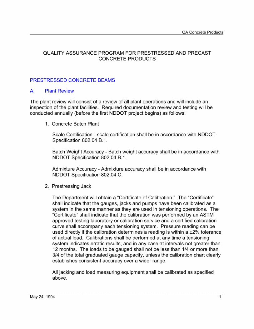
QA Concrete Products
____________________________________________________________________________________ May 24, 1994 1
QUALITY ASSURANCE PROGRAM FOR PRESTRESSED AND PRECAST CONCRETE PRODUCTS
PRESTRESSED CONCRETE BEAMS
A. Plant Review
The plant review will consist of a review of all plant operations and will include an inspection of the plant facilities. Required documentation review and testing will be conducted annually (before the first NDDOT project begins) as follows:
1. Concrete Batch Plant
Scale Certification - scale certification shall be in accordance with NDDOT Specification 802.04 B.1.
Batch Weight Accuracy - Batch weight accuracy shall be in accordance with NDDOT Specification 802.04 B.1.
Admixture Accuracy - Admixture accuracy shall be in accordance with NDDOT Specification 802.04 C.
2. Prestressing Jack
The Department will obtain a “Certificate of Calibration.” The “Certificate” shall indicate that the gauges, jacks and pumps have been calibrated as a system in the same manner as they are used in tensioning operations. The “Certificate” shall indicate that the calibration was performed by an ASTM approved testing laboratory or calibration service and a certified calibration curve shall accompany each tensioning system. Pressure reading can be used directly if the calibration determines a reading is within a ±2% tolerance of actual load. Calibrations shall be performed at any time a tensioning system indicates erratic results, and in any case at intervals not greater than 12 months. The loads to be gauged shall not be less than 1/4 or more than 3/4 of the total graduated gauge capacity, unless the calibration chart clearly establishes consistent accuracy over a wider range. All jacking and load measuring equipment shall be calibrated as specified above.

QA Concrete Products
____________________________________________________________________________________ May 24, 1994 2
Calibration records shall show the following data:
• Date of calibration. • Agency or laboratory supervising the calibration. • Method of calibration; i.e., proving ring, load cell, testing machine, etc.,
and its calibration reference. • The full range of calibration with gauge readings indicated against
actual load.
Calibration records for all tensioning systems in use shall be kept on hand for use in preparing theoretical tensioning values. Personnel involved in preparing tensioning calculations shall have a copy of these records for reference. Sections 2.1.4 and 2.1.7 of the PCI “Manual for Plants and Production of Precast and Prestressed Concrete Products” may be used as a reference for the prestressing jacks.
3. Water Testing
Water testing shall be conducted annually if the water source is questionable, i.e., well water. Testing shall be in accordance with NDDOT Specification 812.
4. Quality Control Evaluation
The Materials and Research Division of the NDDOT will annually evaluate the fabricators QC program. The adequacy of the fabricator's QC program will determine the waiver of NDDOT Specifications Sections 604.02 A, 604.02 C, and 604.02 D, and the level of verification testing by NDDOT. Divisions I and VI of the PCI “Manual for Plants and Production of Precast and Prestressed Concrete Products” may be used as reference for this evaluation.
B. Project/Production Review 1. Mix Design
A written mix design for each project will be provided by the fabricator and shall include the following information:
• Type and amount of cement. • Amount of water. • Amount, maximum size, and coarse aggregate source. • Amount and fine aggregate source. • Amount and types of admixtures.

QA Concrete Products
____________________________________________________________________________________ May 24, 1994 3
• Fines/total aggregate ratio. • Water/cement ratio. • Unit weight of concrete mix. • Maximum slump of concrete mix.
This mix design shall be reviewed prior to the initial inspection. Section 3.1 of the PCI “Manual for Plants and Production of Precast and Prestressed Concrete Products” may be used as reference for mix designs.
2. Production Observation
Materials and Research Division will observe 25 to 50% of the beams fabricated for each project. The observation will be conducted on the first set of beams fabricated on each project and then randomly thereafter. Division V of the PCI “Manual for Plants and Production of Precast and Prestressed Concrete Products” may be used as reference for the production observations. The observation will address the following:
a. Initial Tensioning
The placement and the amount of tensioning in the prestressing cables shall be in accordance with the approved shop drawings. This shall be done by checking the readings on the calibrated jacks and observing the elongation of the cables. Section 2.2 of the PCI “Manual for Plants and Production of Precast and Prestressed Concrete Products” may be used as reference for the pretensioning.
b. Steel Inventory
The reinforcing steel shall be in agreement with the approved shop drawings for grade, proper size, and quantity before the forms are placed.
c. Steel Placement
The reinforcing steel placement shall be in agreement with the approved shop drawings before the forms are placed. The following are acceptable tolerances: 1. Prestress Cable - The prestress cable shall be within ±1/4" of the
position shown on the approved shop drawings. Cables shall be protected against physical damage and rust or other results of corrosion at all times. Cables shall be free of deleterious material such as grease, oil, wax, or paint. Cables shall not have nicks or kinks.

QA Concrete Products
____________________________________________________________________________________ May 24, 1994 4
Steel that has sustained physical damage at any time shall be rejected. The development of pitting or other results of corrosion, other than rust stain, shall be cause for rejection. Hold down devices for deflected cables shall be placed within ±6" of the approved shop drawing positions.
2. Reinforcing Steel - Reinforcing steel shall be adequately supported by
chairs and rigidly held in place within the forms. Chairs in contact with the forms must be either plastic or stainless steel tipped. Stirrups shall be within ±1" of the position shown in the approved shop drawings. Stirrups projecting above the top of the beam shall be within a tolerance of +1/4", - 3/4". The clear cover shall be within a tolerance of +1/4" to 0". Welding or tack welding of reinforcing steel is prohibited.
3. Inserts - The inserts shall be within ±1/2" of the positions shown on
the approved shop drawings. Any metal devices in contact with the forms shall be galvanized or coated as specified on the plans.
4. Lift Hooks - Lift hooks shall be placed within ±6" of the position shown on the approved shop drawings.
d. Beds and Forms
Beds and forms shall be clean, smooth and without warps; set on a rigid foundation; able to withstand fluid pressures of concrete; mortar tight at all joints; accurately built to the proper dimensions; and coated with a release agent.
e. Concrete
The concrete's slump and temperature shall be recorded. In addition, air temperature and weather conditions shall be recorded. Batching equipment shall be capable of achieving a rate of pour that will avoid cold joints and will allow float finishing of the top of the beam before initial set. If the vibrator will not sink under its own weight, a cold joint has developed. When cold joints have developed, the partially cast member shall be rejected. Section 3.3 of the PCI “Manual for Plants and Production of Precast and Prestressed Concrete Products” may be used as reference for a concrete pour.
f. Curing Process
The fabricator shall cure the beams by steam or radiant heat if the

QA Concrete Products
____________________________________________________________________________________ May 24, 1994 5
ambient air temperature does not provide an adequate cure. The concrete shall reach its initial set before application of steam or heat curing. Time of set may be determined by ASTM C 403. During the initial set period the curing chamber temperature must be maintained at or above 50°F. The fabricator shall have a least two maximum and minimum temperature recording thermometers per curing chamber. The maximum curing temperature shall not exceed 160°F. Section 3.4 of the PCI “Manual for Plants and Production of Precast and Prestressed Concrete Products” may be used as reference for the curing process.
g. Detensioning
The detensioning shall not be done until control cylinders, cured with the beams, indicate the concrete has reached the design prestress transfer stress, or 4,000 psi, whichever is greater. The forms, ties, inserts, hold-downs or other devices that would restrict longitudinal movement of the beams along the bed shall be removed. Heating of individual strands shall be done simultaneously at a minimum of two locations along the casting bed. The sequence of the heating of each strand along the bed, and the sequence between strands, and the release of hold down devices, shall be accomplished so that no damage occurs to the girder. Detensioning by simply cutting the strand with a shear will not be allowed. Section 2.3 of the PCI “Manual for Plants and Production of Precast and Prestressed Concrete Products” may be used as reference for detensioning operations.
h. Beam Dimensions
To ensure that the beams have been accurately cast to the dimensions shown on the plans, all major dimensions of five completed beams selected randomly from each NDDOT project shall be measured, including length, height, flange widths, sweep and camber. In addition, the fabricator's quality control paperwork shall be reviewed by the Materials and Research Division with regard to beam dimensions for the remaining beams. Tolerances for as build dimensions shall be as per PCI Specifications 6.4. Camber shall be measured not sooner than 24 hours after the beam has been cast.
i. Acceptance
Beams cast that vary from the approved shop drawings with respect to dimensions; reinforcement steel size, quantity, or location; prestressing cable size, quantity, or location; and void form size or location shall be

QA Concrete Products
____________________________________________________________________________________ May 24, 1994 6
subject to rejection or evaluation by the Department Bridge Engineer. If honeycombing is present or any reinforcing or prestressing cable is exposed at the time of form removal, a beam shall be subject to rejection by the Department Bridge Engineer. Beam repairs shall be submitted in writing and approved by the Department Bridge Engineer. Any variation from approved shop drawings shall be subject to rejection by the Department Bridge Engineer if said Engineer determines that the variation will result in an inferior product. After Materials and Research Division has determined that the beam has been constructed in accordance with the approved shop drawings, the beam will receive the Department stamp. The Materials and Research Division shall record all beams dimensions, any repair work, and the date stamped. Final acceptance of beams will be conducted by the project engineer.
3. Materials Testing
a. Random Aggregate Testing
One random test shall be performed for each project in accordance with NDDOT Specification 816.01 A.2 for fine aggregate and 816.02 A.2 for coarse aggregate. Sodium sulfate soundness tests may be omitted if this test has been run on the source pit.
b. Random Cement Testing
Three random samples shall be tested each construction season or one test with a change in source. Testing shall be in accordance with NDDOT Specification 804.01.
c. Steel Strand Testing
One test shall be performed on each new lot. Testing shall be in accordance with NDDOT Specification 836.03.
d. Rebar and Cage Testing
Three tests shall be performed each year. Testing shall be in accordance with NDDOT Specifications 836.02 and 836.03.

QA Concrete Products
____________________________________________________________________________________ May 24, 1994 7
e. Admixtures
All admixtures shall be tested at the rate of one test per lot. Testing shall be in accordance with NDDOT Specification 808.
f. Freeze-Thaw Testing
One set of bars shall be cast every year and when the admixture amount or lot changes.
g. Concrete Strength Testing
One set of three cylinders on three random occasions shall be cast each year for verification. The average concrete strength of the fabricator’s cylinders must be within 5% of the Department average cylinder strength.
4. Certifications
Materials and Research Division will review the manufacturer’s QC documentation and applicable certifications and affidavits for materials used to produce each of a project’s beams. These will also be reviewed by the project engineer.
PRECAST CONCRETE PIPE A. Plant Review
The plant review will be conducted by the District Materials Coordinators. The plant review will consist of a review of all plant operations and will include an inspection of the plant facilities. Required documentation, review, and testing will be conducted annually as follows:
1. Concrete Batch Plant
Scale Certification - Scale certification shall be in accordance with NDDOT Specification 802.04 B.1. Batch Weight Accuracy - Batch weight accuracy shall be in accordance with NDDOT Specification 802.04 B.1. Admixture Accuracy - Admixture accuracy shall be in accordance with NDDOT Specification 802.04 C.

QA Concrete Products
____________________________________________________________________________________ May 24, 1994 8
2. Three-Point Bearing Jack
District Materials Coordinators shall review the independent laboratories results of the three-point bearing tests conducted at least three times a year. The District Materials Coordinators will document the review and report results to the Materials and Research Division. In addition, the District Materials Coordinators will review the three-point bearing jack calibration documentation annually.
Calibration records shall show the following data:
• Date of calibration. • Agency or laboratory supervising the calibration. • Method of calibration; i.e., proving ring, load cell, testing machine, etc., and its calibration reference. • The full range of calibration with gauge readings indicated against actual load.
3. Water Testing
Water testing shall be conducted annually if the water source is questionable, i.e., well water. Testing shall be in accordance with NDDOT Specification 812.
4. Quality Control Evaluation
District Materials Coordinators will annually evaluate the fabricators QC program. The evaluation and a typed copy of the QC program shall be sent to the Materials and Research Division. The District Materials Coordinators will review all certifications for individual projects.
B. Materials Testing 1. Random Aggregate Testing
Three random tests shall be performed each year or when the source changes. The testing shall be conducted in accordance with NDDOT Specification 816.01 A.2 for fine aggregate and 816.02 A.2 for coarse aggregate. Sodium sulfate soundness tests may be omitted if this test has been run on the source pit. Aggregate testing may be omitted if similar tests have been conducted by the Department for a different concrete product, i.e., prestressed beams or precast box culverts. The District Materials Coordinator will review all certifications for this material.

QA Concrete Products
____________________________________________________________________________________ May 24, 1994 9
2. Random Cement Testing
Three random samples shall be tested each construction season or one test with a change in source. Testing shall be in accordance with NDDOT Specification 804.01. Cement testing may be omitted if similar tests have been conducted by the Department for a different concrete product, i.e., prestressed beams or precast box culverts. The District Materials Coordinator will review all certifications for this material.
3. Rebar and Cage Testing
Three tests shall be performed each year. Testing shall be in accordance with NDDOT Specifications 836.02 and 836.03. Rebar and cage testing may be omitted if similar tests have been conducted by the Department for a different concrete product, i.e., prestressed beams or precast box culverts. The District Materials Coordinator will review all certifications for this material.
4. Admixtures
All admixtures shall be tested at the rate of one test per lot. Testing shall be in accordance with NDDOT Specification 808. Admixture testing may be omitted if similar tests have been conducted by the Department for a different concrete product, i.e., prestressed beams or precast box culverts. The District Materials Coordinator will review all certifications for this material.
5. Absorption Testing
Two samples shall be taken per year per plant and sent to the Materials and Research Division for absorption testing. One sample can be taken each construction season for absorption verification testing if the manufacturer is doing frequent absorptions. The samples may be taken from the wall of the pipe after they have been strength tested for Dultimate. The samples shall not be from the same pipe size. Absorption tests may not be omitted.
6. Strength Testing
One pipe section for each pipe size, up to 60", used on NDDOT construction projects each year shall be obtained for three-edge-bearing testing for D0.01 and Dultimate. Pipe sections greater than 60” shall be tested for compressive strengths using molded cylinders. Strength testing is not required for concrete end sections. This verification testing cannot be omitted. The District Materials Coordinator will review all of the manufacturer’s compression test results for concrete.

QA Concrete Products
____________________________________________________________________________________ May 24, 1994 10
7. Acceptance
When all of the above test results meet specifications and the District Materials Coordinator determines that the plant is in compliance, then 100% of the precast concrete pipe produced at the subject plant may be accepted on certification. The final acceptance will be conducted by the project engineer. If one or more of the above material tests fail, the District Materials Coordinator will increase the sampling and testing frequency. Precast concrete pipe will not be accepted on certification for the lot represented by the failed tests. Testing will then be in accordance with Section 830.01. The precast concrete pipe may be accepted on certification when the quality control and quality assurance tests indicate that the product is within specification.
PRECAST BOX CULVERTS A. Plant Review
The plant review will be conducted by the District Materials Coordinators. The plant review will consist of a review of all plant operations and will include an inspection of the plant facilities. Required documentation review and testing will be conducted annually as follows:
1. Concrete Batch Plant Scale Certification - Scale certification shall be in accordance with NDDOT Specification 802.04 B.1. Batch Weight Accuracy - Batch weight accuracy shall be in accordance with NDDOT Specification 802.04 B.1. Admixture Accuracy - Admixture accuracy shall be in accordance with NDDOT Specification 802.04 C.
2. Water Testing
Water testing shall be conducted annually if the water source is questionable, i.e., well water. Testing shall be in accordance with NDDOT Specification 812.

QA Concrete Products
____________________________________________________________________________________ May 24, 1994 11
3. Quality Control Evaluation
District Materials Coordinators will annually evaluate the fabricators QC program. The evaluation and a typed copy of the QC program shall be sent to the Materials and Research Division. The District Materials Coordinators will review all certifications for individual projects.
B. Materials Testing
1. Random Aggregate Testing
Three random tests shall be performed each year or when the source changes. The testing shall be conducted in accordance with NDDOT Specification 816.01 A for fine aggregate and 816.02 A for coarse aggregate. Sodium sulfate soundness tests may be omitted if this test has been run on the source pit. Aggregate testing may be omitted if similar tests have been conducted by the Department for a different concrete product, i.e., prestressed beams or precast concrete pipe. The District Materials Coordinator will review all certifications for this material.
2. Random Cement Testing
Three random samples shall be tested each construction season or one test at a change in source. Testing shall be in accordance with NDDOT Specification 804.01. Cement testing may be omitted if similar tests have been conducted by the Department for a different concrete product, i.e., prestressed beams or precast concrete pipe. The District Materials Coordinator will review all certifications for this material.
3. Rebar and Cage Testing
Three tests shall be performed each year. Testing shall be in accordance with NDDOT Specifications 836.02 and 836.03. Rebar and cage testing may be omitted if similar tests have been conducted by the Department for a different concrete product, i.e., prestressed beams or precast concrete pipe. The District Materials Coordinator will review all certifications for this material.
4. Admixtures
All admixtures shall be tested at the rate of one test per lot. Testing shall be in accordance with NDDOT Specifications 808. Admixture testing may be omitted if similar tests have been conducted by the Department for a different concrete product, i.e., prestressed beams or precast concrete pipe. The

QA Concrete Products
____________________________________________________________________________________ May 24, 1994 12
District Materials Coordinator will review all certifications for this material.
5. Compression Testing
The District Materials Coordinator will review all of the manufacturer’s compression test results for concrete.
C. Production Observation
The District Materials Coordinators will inspect the first section of a box culvert for each project. If fabrication does not occur in the District Materials Coordinator's own district, then the District Materials Coordinator shall make arrangements with the Materials and Research Division or another District. The District Materials Coordinator is to conduct the required observation. This observation will address the following:
1. Steel Inventory
The reinforcing steel shall be in agreement with the approved shop drawings for grade, proper size, and quantity, before the forms are placed.
2. Steel Placement
The reinforcing steel placement shall be in agreement with the approved shop drawings, before the forms are placed. The reinforcing steel shall be adequately supported by chairs and rigidly held in place within the forms. Chairs in contact with the forms must be either plastic or stainless steel tipped.
3. Forms
Forms shall be clean, smooth and without warps; able to withstand fluid pressures of concrete; mortar tight at all joints; accurately built to the proper dimensions; and coated with a release agent.
4. Acceptance
Box culverts cast that vary from the approved shop drawings with respect to dimensions, reinforcement steel size, quantity, or location shall be subject to rejection or evaluation by the Department Bridge Engineer. If honeycombing is present, or if any reinforcing steel is exposed at the time of form removal, the box culvert shall be subject to rejection by the Department Bridge

QA Concrete Products
____________________________________________________________________________________ May 24, 1994 13
Engineer. Any repairs to the box culvert shall be submitted in writing and approved by the Department Bridge Engineer. Any variation from approved shop drawings shall be subject to rejection by the Department Bridge Engineer, if said Engineer determines that the variation will result in an inferior product. Final acceptance of box culvert will be conducted by the project engineer.

REINFORCED CONCRETE PIPE TEST AND INSPECTION RECORDNorth Dakota Department of Transportation, Materials & ResearchSFN 10093 (Rev. 04-2000)
DATE OF TESTTESTED BYPLANT LOCATIONMANUFACTURER
3 Edge Bearing TestWall ThicknessLengthInternal Diameter
Remarks:
DNC - Did Not Crack - ApprovedHC - Hair Crack - Less than 0.01" - ApprovedDNP - Did Not Pass - Crack over 0.01"
*Code:Distribution: 1- Dept. Files
Dateof
TestPiece
Classof
PipeNominalInches
ActualInches
MeetsRequire-
ments
NominalFeet
ActualFeet -Inches
MeetsRequire-ments
NominalInches
ActualInches
MeetsRequire-ments
RequiredLoadLbs.
AppliedLoadLbs.
Result*
Dateof
PiecesStamped
Numberof
PiecesStamped

____________________________________________________________________________3/13/2019 Page 1 of 2
Field Sampling and Testing Manual Revisions and Additions
Approved and Effective Date: March 13, 2019
Section 200: • Appendix 200A “Consultant Use of Nuclear Gauges for Compaction Control” (new) -
added to 200 Section to replace M&R Memorandum 1-2010 deleted
Section 300: • Section 302 “Aggregate Base and Surface Course” (new revision) • Section 304 “Permeable Stabilized Base” deleted • Section 306 “Full Depth Reclamation” (new) • Section 306 “Blended Base Course” deleted
Section 400:
• Section 421 “Micro Surfacing (complete revision) • Section 422 “Slurry Seal” (complete revision) • Appendix 400A “Acceptance of Performance Graded Asphalt for County Projects
with Federal Aid” (new) and added to 400 section -M&R Memorandum 1-1999 deleted • Section 430 “Hot Mix Asphalt” Revisions follow:
The word testing has been replaced by “responsibility” throughout. Page 7 d. removed “from behind the paver” in first sentence. Page 7 e. there were two of the same paragraphs had to remove one. Page 8 B. removed the second sentence in the first paragraph “Core samples are to be obtained according to NDDOT 2 Contractor Sampling.” Page 8 C.1 in the second sentence of first paragraph removed “behind” and added “at”. Page 10 first paragraph, first sentence replaced “IA” test with “additional”. Page 10 first paragraph, second sentence was reworded and “IA” was replaced with District Materials Coordinator. Page 11 first paragraph first two sentences changed to be same as on page 10. Page 11 third paragraph from top changed “IA lab” to “District Materials Coordinator.” Page 11 under section 2, third paragraph down removed second sentence and last sentence of that paragraph. Page 12 under 430.04 the last three sentences replaced or removed “laboratory” to “Division,” and removed “NDDOT”. Page 14 added a title to B. and C. Page 15 in the last sentence before the D. heading, changed QA “lab” to QA “tester.” Page 16 and 17 added new section 430.06 Material and Research Division Program Oversight.
Section 500: • Section 550 “Concrete Pavement” Revisions:
Page 2, Table 550-2 – removed asterisks under “Frequency” and removed this part of the sentence under the table “or a maximum of three tests per day.

____________________________________________________________________________3/13/2019 Page 2 of 2
• Section 570 “Concrete Pavement Repair” (new) • Section 575 “Dowel Bar Retrofit” (new)
Procedures:
• ND T 2, “Sampling of Aggregates (small revision – reformatted first page) • ND T 176, “Plastic Fines in Graded Aggregates and Soils by Use of the Sand Equivalent
Test” (small revision – deleted one paragraph on page 2 inbetween 2nd and 4th para.) • NDDOT 1, “Sampling of Bituminous Materials” (revision to whole document) • NDDOT 5, “Sampling and Splitting Field Verification Hot Mix Asphalt (HMA) Samples”
(revision to whole document) • NDDOT 2, “Contractor Coring” deleted
“Memorandum” Section - deleted whole section
• Memorandums have either become obsolete or incorporated within other sections

6/1/2016 Revision Table Page 1 of 7
NDDOT FIELD SAMPLING AND TESTING MANUAL
CHANGES TO MANUAL SINCE 8/2007
Section Name Description Date Revised
Web Date
2016 Changes
Section 100 • 106
Revised Section 106. Clarified what Independent Assurance (IA) is and we are responsible for local roads on NHS projects.
6/1/2016 6/6/2016
Section 200 • 203, 210
Sections 203 and 210 have been revised. Old versions are to be discarded and replaced.
6/1/2016 6/6/2016
Section 400 • 401, 411 • 420, 421, 422
With the exception of Section 430 that was added in 2015, the 400 section has been totally replaced with Section 401, 411, 420, 421, 422. Forms also have been updated with new versions where necessary. Except for section 430, the old 400 section including appendices are to be discarded and replaced.
6/1/2016 6/6/2016
Section 500 • 550
Section 550 is new and is the only section that is under the 500 section at this time. Discard and replace the old Section 500.
6/1/2016 6/6/2016
Test Procedures • ND T 176
Procedural revisions have been made to ND T 176 for the sand equivalent test. Discard and replace old version.
5/1/2016 6/6/2016
Section Forms Forms referenced in the back of each section in which they are used are for reference only. As forms are revised they are placed on the NDDOT internet website under the “FORMS” heading and these are the ones to be used when working projects. The forms in the manual may not be updated with every new revision. Use the current form and discard all old paper versions when a form is revised.
Forms • SFN 2454, • SFN 59725
SFN 2454 “Density Test Worksheet - Volume Measure”, and SFN 59725 “Density Test Worksheet - Sand Cone Method,” have been revised to document the lot numbers.
5/2016 5/2016

6/1/2016 Revision Table Page 2 of 7
Section Name Description Date Revised
Web Date
2015 Changes
Section 400 • Section 430
has been added
Section 430, “Hot Mix Asphalt (HMA) Testing and Sampling Requirements,” has been added to Section 400. Section 430 is to be used with 2015 projects. This section replaces 402, 403, 407, 408, 409, 410, and the appendices in Section 400. The old sections will remain in the Field Sampling and Testing Manual until all 2014 construction projects are completed.
5/22/2015 5/27/2015
Testing Procedures Section
‘Testing Procedures” chapter - Replaced in its entirety. All NDDOT procedures that are modified from AASHTO or ASTM methods, are re-identified as an ND instead of as AASHTO or ASTM (e.g., ND T 2). In addition, procedure “ND T 113” had errors in two formulas under ‘Calculations’. The formulas were corrected to be divided by 100.
2/13/2015 2/20/2015
2014 Changes
Section 700 • 709 • Table of
Contents
709 ‘Geotextile Materials’ - Changed in its entirety. 6/26/2014 6/27/2014
Section 700 • 714 • Table of
Contents
714 ‘Culverts, Storm Drains, Edge Drains, and Underdrains’ - Changed in its entirety. Added edge drains to the section. Added acceptance samples and tests for metallic culverts, concrete pipe, plastic pipe, underdrain granular fill materials. Added acceptance samples and tests for compaction control for pipe backfill. Added independent assurance samples and tests compaction control for pipe backfill. Added independent assurance samples and tests for underdrain.
3/19/2014 3/20/2014
Section 200 • 210
Revisions made to 210.1 Acceptance Samples and Tests and 210.2 Independent Assurance Samples and Tests. Replaced SFN 13889 & DOT 13942 with updated versions in Section 200.
3/19/2014 3/20/2014

6/1/2016 Revision Table Page 3 of 7
Section Name Description Date Revised
Web Date
2013 Changes
400 Section • 410
On page 3 in the 2nd last paragraph, added all AASHTO testing specifications needed to be referenced after obtaining an aggregate sample, to be consistent within all of Section 410. On page 6, the very last sentence was changed to reference “table on page 7” instead of saying “table below.”
1/8/2013 1/14/2013
2012 Changes
Testing Procedures • AASHTO T 2
Page 3 under “Sampling from a Windrow”, the first sentence was deleted. On page 4 in the 1st paragraph, the 1st word of 2nd sentence-the word “shove” was replaced with “insert”. Also page 4 under “Sampling from a Truck,” the 2nd paragraph was rewritten for clarification.
12/26/2012 1/14/2013
Testing Procedures • AASHTO T 166
Page 1 under “Referenced Documents” we added AASHTO T 331. Under “Apparatus” added words “with overflow outlet” behind Water bath. Under “Procedure”, page 1, removed the 2nd sentence in the 2nd paragraph. Under “Calculations” in the very last sentence added reference to AASHTO T 331, and under “Notes” added 1st sentence.
12/26/2012 1/14/2013
Testing Procedures • AASHTO T 209
Corrected title to be same as current AASHTO Standard Spec book. Under “Apparatus” corrected measurement by Vacuum gage and pump to (4 kPa); and changed written order of the Volumetric flasks item. Under Procedures on page 2, paragraph 8 corrected measurement to read (4 kPa). Page 3 in 1st paragraph added a) sign that was missing from (8 kPa).
12/26/2012 1/14/2013
Testing Procedures • AASHTO T 304
Page 1, under “Apparatus” behind Metal spatula added “with straight edge”. Page 2, under “Test Specimen” rewrote the 4th paragraph beginning with word “Remove” and corrected the table below it to reflect the changes of the paragraph. Under “Procedure” on page 2 in last paragraph, added word “rapid” before “single pass”, and added 2nd sentence of same paragraph starting with “The blade……”
12/28/2012 1/14/2013
Testing Procedures • AASHTO T 312
Page 2 identified the “Mixture Preparation” and the “Compaction Procedure”. Added temperature ranges of the oven within each of these 2 sections for °F and °C.
12/26/2012 1/14/2013

6/1/2016 Revision Table Page 4 of 7
Section Name Description Date Revised
Web Date
Testing Procedures • NDDOT 5
Page 1 under “Referenced Documents” removed the two words “paving mixtures” at end of AASHTO T 209 and corrected typing error in T 312. Under “Procedure” in the 1st paragraph the weights were changed. In the 2nd sentence of same paragraph words “Marshall” and “only” were added.
12/26/2012 1/14/2013
Appendix 400-A-2-C Added clarification to No. 7 about the QC acceptance sample 7/26/2012 7/26/2012
Appendix 400-A-2-A Corrected an error in the description of the revision. Changed 1st sentence to read 2nd sentence.
6/2012 6/2012
Table of Revisions A table of revisions has been added to the web manual. This table details all changes that have taken place within the manual since updated sections have been placed on the web in August, 2007.
5/2012 5/2012
Section 100, 500, 600, 700, 800, Frequency Table
No revisions made. Added to the web as is. These old sections of FS&TM are in the process of being revised. Newest versions of these sections will be placed on web after approved by the FHWA.
5/2012 5/2012
Section 200 • Table of
Contents
Updated the table of contents of the 200 Section to reflect that changes were made in SFN 2454 and 59725.
3/6/2012 3/6/2012
• Forms in Sec. 200
Updated two forms at the end of the 200 Section. SFN 2454 – enlarged columns for fill-in. SFN 59725 corrected formula in m. Moisture loss = k – l (replaced the i with an l).
3/6/2012 3/6/2012
Section 400 • Appendix 400-
C4
Page 2, under 400-C-4-1, corrected the 23.36 mm to 2.36 mm. Also had to add “400-C-4 Fine Aggregate Test Modifications” to page 2 of the table of contents.
3/1/2012 3/5/2012
Section 200 Replaced text portion of 200 Section and added 2 forms. Added reference to AASHTO T 191 procedure to all sections where needed. Added reference to AASHTO T 99 and T 180 to all sections where they were missing. Added two forms to the end of the section: SFN59724 and SFN 59725 regarding sand cone correction factor and density test worksheet. Made reference to these forms throughout Section 200.
1/24/2012 1/27/2012

6/1/2016 Revision Table Page 5 of 7
Section Name Description Date Revised
Web Date
AASHTO T 99/T 180 Replaced all of T 99/T 180. Removed the written AASHTO T 265 procedure on page 5 but kept reference to it. T 265 already exists under the procedure section. Size reduced to 8 pages. Revised the “Method D” table (pg. 2) by changing the ‘soil passing sieve’ from No. 4 to 3/4".
1/12/2012 1/17/2012
AASHTO T 265 Replaced both pages of T 265. Revised formula under “Calculations” according to the “AASHTO Standard Specifications of Transportation Materials & Methods of Sampling and Testing” (pg. 2).
1/12/2012 1/17/2012
ASTM D 4643 Replaced both pages of D 4643. Revised formula under “Calculations” according to “AASHTO Standard Specs of Transportation Materials & Methods of Sampling and Testing” (pg. 2).
1/12/2012 1/17/2012
Memorandums Added M&R Memo 1-1999 “PG Asphalt Sampling and Testing on Federal Aid County Projects,” and M&R Memo 2-2009 “Rapid and Quick Set Emulsion Testing.” Revised and replaced the Memorandums “Table of Contents.”
1/3/2012 1/6/2012
2011 Changes
Section 400 Replaced complete 400 Section. Revised the reference to the ASTM D 244 procedure to the T 59 procedure (ASTM D 244 was discontinued); SFN 19802 was deleted and any reference to it was changed with SFN 59132; replaced forms to the current version.
6/22/2011 8/5/2011
• Appendix 400-A-1C
Added reference to “contract documents” (pg. 1). 6/22/2011 8/5/2011
• Appendix 400-A-2A
Added “contract documents” to end of 2nd sentence (pg. 1); Added 3rd paragraph on splitting QC samples (pg. 2); Added last 2 sentences to last paragraph: “If the QC and Verification test results do not agree……”(pg. 2)
6/22/2011 8/5/2011
• Appendix 400-A-2B
Added reference to “contract documents” (pg. 2); Added item No. 5 about QC split samples (pg. 3)
6/22/2011 8/5/2011
• Appendix 400-A-2C
Add item No. 7 about Contractor IA run tests (pg. 4). 6/22/2011 8/5/2011

6/1/2016 Revision Table Page 6 of 7
Section Name Description Date Revised
Web Date
• Appendix 400-A-3 Added last paragraph in table under the “Verification Testing” regarding split QC sample (pg. 6).
6/22/2011 8/5/2011
• Appendix 400-D Added appendix to manual 6/17/2011 8/5/2011 • Appendix 400-E Added appendix to manual 8/1/2011 8/5/2011
AASHTO T 99/T 180 Test Procedure
Revised/added paragraph 3, 4, 5 (pg. 1); the Method D table (pg. 2); the Method A & Method D under “Sample Size” (pg. 2); added 2 statements referencing method D with * and ** (pg. 3).
6/17/2011 8/5/2011
AASHTO T 191 Test Procedure
Added sand cone form numbers SFN 59725 and SFN 59724 as a reference in 1st paragraph under “Procedure” (pg. 3)
6/17/2011 8/2011
AASHTO T 224 Test Procedure
Corrected formulas (pg. 2) 6/16/2011 8/2011
AASHTO T 245 Test Procedure
Corrected table on pg. 4 “Correction Factor Table” 6/22/2011 8/2011
2010 Changes
AASHTO T 84 Removed 3rd paragraph on pg. 1 2/10/2010 2/2010 AASHTO T 113 2/10/2010 2/2010 Memorandums Added Memo 1-2010 “Use of Nuclear Gauges on Soils or Aggregates” 5/20/2010 8/2010 Appendix 400-B Corrected air voids % on pg. 3 11/15/2010 11/2010 2009 Changes
Memorandums Added M&R Memo 1-2009 “Sampling Soils or Soil Aggregates for Pipe Backfill Acceptance
7/29/2009 8/2009
Section 210.1 Modified compaction control of pipe in 1st paragraph under “Field Lab Testing Compaction ……..” (pg. 1)
6/16/2009 8/2009
Section 302.1, pg. 2 Added last 2 sentences at end of 1st paragraph on sampling frequency of failing samples
7/23/2009 8/2009
Section 306.1 pg. 1 Added last 2 sentences of 4th paragraph for lot acceptance testing 7/23/2009 8/2009 Section 300 Forms Added forms at section end: 10072, 13889,14388 7/23/2009 8/2009 AASHTO T 84 Added 3rd paragraph on pg. 1 1/30/2009 3/2009 AASHTO T 191 Added procedure to manual 5/28/2009 8/2009

6/1/2016 Revision Table Page 7 of 7
Section Name Description Date Revised
Web Date
AASHTO T 224 Added procedure to manual 7/1/2009 8/2009 2008 Changes
Section 230.1 Added last paragraph on embankment widening 3/12/2008 8/2008 Section 230.2 Added last sentence of 1st paragraph on test frequency for embankment widening 3/12/2008 8/2008 Memorandums Added Memo 1-2008 physical property testing of aggregate 8/1/2008 8/2008 2007
Disclaimer Added – new original 8/2007 Section 200 Added – new original 8/2007 Section 300 Added – new original 8/2007 Section 400 Added – new original 8/2007 Testing Procedures Added – new original 8/2007 Rounding Procedures
Added – new original 8/2007
Random Sampling Added – new original 8/2007 M&R Memorandums Added – new original 8/2007 QA Program of Concrete Products
Added – new original 8/2007

Intentionally Left Blank