ncs6 seriesto jedec jesd22-b106 iss c) 260 c minimum output load for specification (see application...
TRANSCRIPT
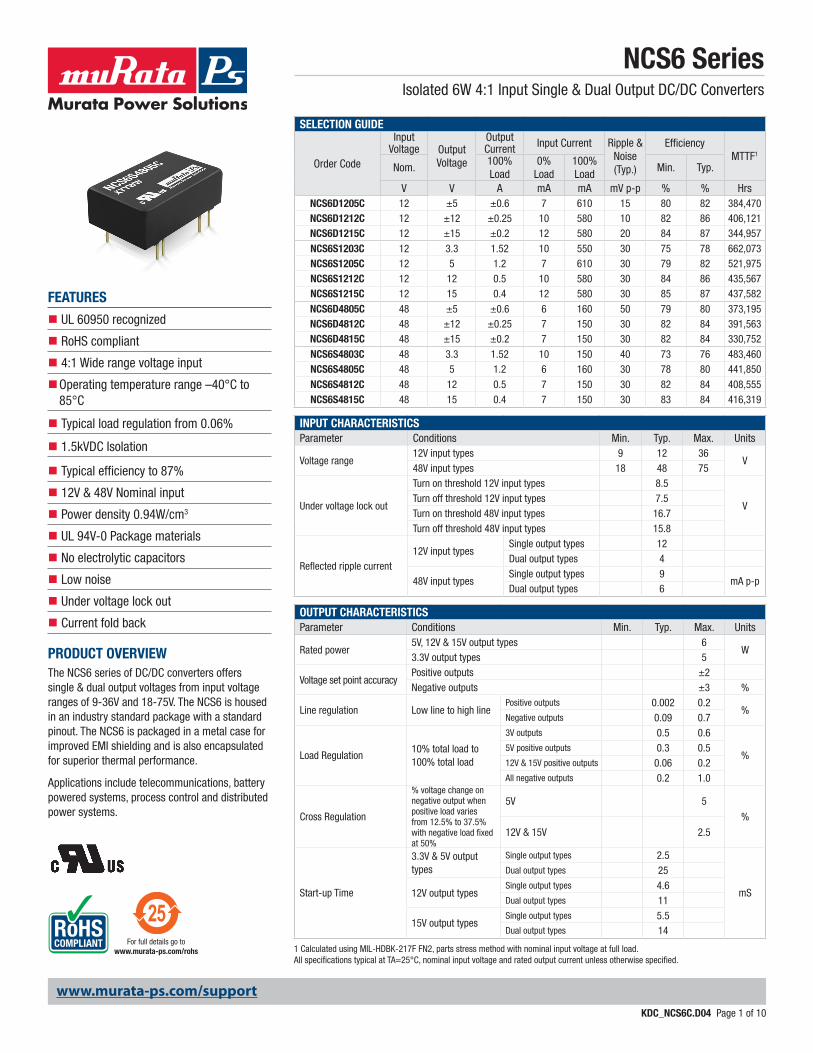
NCS6 SeriesIsolated 6W 4:1 Input Single & Dual Output DC/DC Converters
KDC_NCS6C.D04 Page 1 of 10
www.murata-ps.com
www.murata-ps.com/support
For full details go towww.murata-ps.com/rohs
SELECTION GUIDE
Order Code
Input Voltage Output
Voltage
Output Current Input Current Ripple &
Noise(Typ.)
EfficiencyMTTF1
Nom.100% Load
0% Load
100% Load
Min. Typ.
V V A mA mA mV p-p % % HrsNCS6D1205C 12 ±5 ±0.6 7 610 15 80 82 384,470NCS6D1212C 12 ±12 ±0.25 10 580 10 82 86 406,121NCS6D1215C 12 ±15 ±0.2 12 580 20 84 87 344,957
NCS6S1203C 12 3.3 1.52 10 550 30 75 78 662,073NCS6S1205C 12 5 1.2 7 610 30 79 82 521,975NCS6S1212C 12 12 0.5 10 580 30 84 86 435,567NCS6S1215C 12 15 0.4 12 580 30 85 87 437,582
NCS6D4805C 48 ±5 ±0.6 6 160 50 79 80 373,195NCS6D4812C 48 ±12 ±0.25 7 150 30 82 84 391,563NCS6D4815C 48 ±15 ±0.2 7 150 30 82 84 330,752
NCS6S4803C 48 3.3 1.52 10 150 40 73 76 483,460NCS6S4805C 48 5 1.2 6 160 30 78 80 441,850
NCS6S4812C 48 12 0.5 7 150 30 82 84 408,555NCS6S4815C 48 15 0.4 7 150 30 83 84 416,319
INPUT CHARACTERISTICSParameter Conditions Min. Typ. Max. Units
Voltage range12V input types 9 12 36
V48V input types 18 48 75
Under voltage lock out
Turn on threshold 12V input types 8.5
VTurn off threshold 12V input types 7.5Turn on threshold 48V input types 16.7Turn off threshold 48V input types 15.8
Reflected ripple current12V input types
Single output types 12Dual output types 4
48V input typesSingle output types 9
mA p-pDual output types 6
OUTPUT CHARACTERISTICSParameter Conditions Min. Typ. Max. Units
Rated power5V, 12V & 15V output types 6
W3.3V output types 5
Voltage set point accuracyPositive outputs ±2Negative outputs ±3 %
Line regulation Low line to high linePositive outputs 0.002 0.2
%Negative outputs 0.09 0.7
Load Regulation10% total load to 100% total load
3V outputs 0.5 0.6
%5V positive outputs 0.3 0.512V & 15V positive outputs 0.06 0.2All negative outputs 0.2 1.0
Cross Regulation
% voltage change on negative output when positive load varies from 12.5% to 37.5% with negative load fixed at 50%
5V 5
%
12V & 15V 2.5
Start-up Time
3.3V & 5V output types
Single output types 2.5
mS
Dual output types 25
12V output typesSingle output types 4.6Dual output types 11
15V output typesSingle output types 5.5Dual output types 14
1 Calculated using MIL-HDBK-217F FN2, parts stress method with nominal input voltage at full load. All specifications typical at TA=25°C, nominal input voltage and rated output current unless otherwise specified.
FEATURES
n UL 60950 recognized
n RoHS compliant
n 4:1 Wide range voltage input
n Operating temperature range –40°C to 85°C
n Typical load regulation from 0.06%
n 1.5kVDC Isolation
n Typical efficiency to 87%
n 12V & 48V Nominal input
n Power density 0.94W/cm3
n UL 94V-0 Package materials
n No electrolytic capacitors
n Low noise
n Under voltage lock out
n Current fold back
PRODUCT OVERVIEWThe NCS6 series of DC/DC converters offers single & dual output voltages from input voltage ranges of 9-36V and 18-75V. The NCS6 is housed in an industry standard package with a standard pinout. The NCS6 is packaged in a metal case for improved EMI shielding and is also encapsulated for superior thermal performance.
Applications include telecommunications, battery powered systems, process control and distributed power systems.

NCS6 SeriesIsolated 6W 4:1 Input Single & Dual Output DC/DC Converters
KDC_NCS6C.D04 Page 2 of 10
www.murata-ps.com/support
ISOLATION CHARACTERISTICSParameter Conditions Min. Typ. Max. UnitsIsolation test voltage Flash tested for 1 seconds 1500 VDCResistance Viso = 1kVDC 1 GΩCapacitance 225 pF
ABSOLUTE MAXIMUM RATINGSShort-circuit protection (for SELV input voltages) ContinuousInternal power dissipation 2.1W
Lead temperature 1.0mm from case for 10 seconds (to JEDEC JESD22-B106 ISS C)
260°C
Minimum output load for specification (see application notes) 10% of rated loadInput voltage, NCS6 12V input types 40VInput voltage, NCS6 48V input types 80V
GENERAL CHARACTERISTICS1
Parameter Conditions Min. Typ. Max. UnitsSwitching frequency 180 kHz
TEMPERATURE CHARACTERISTICSParameter Conditions Min. Typ. Max. UnitsOperation -40 85
°C
Storage -50 125
Case temperature rise above ambient100% Load, Nom VIN, Still Air
48VIN Dual outputs5V 3612V 3215V 31
All other output types
3.3V 325V 3212V 2815V 26
Thermal shutdown Case Temperature 105
APPLICATION NOTES
Output Capacitors
The NCS6 series does not require output capacitors to meet datasheet specification. To meet datasheet specification, total output capacitance should not exceed:
Output Voltage (V) Output Capacitance (µF)3.3 4705 47012 22015 220
Minimum Load
The minimum load to meet full datasheet specification is 10% of the full rated load across the specified input voltage range. Between 0% and 10% output loading, the positive output voltage will remain within data sheet specification however, output ripple and noise will increase as well as a decrease in accuracy on negative outputs.

NCS6 SeriesIsolated 6W 4:1 Input Single & Dual Output DC/DC Converters
KDC_NCS6C.D04 Page 3 of 10
www.murata-ps.com/support
TECHNICAL NOTES
ISOLATION VOLTAGE‘Hi Pot Test’, ‘Flash Tested’, ‘Withstand Voltage’, ‘Proof Voltage’, ‘Dielectric Withstand Voltage’ & ‘Isolation Test Voltage’ are all terms that relate to the same thing, a test voltage, applied for a specified time, across a component designed to provide electrical isolation, to verify the integrity of that isolation.
Murata Power Solutions NCS6 series of DC/DC converters are all 100% production tested at their stated isolation voltage. This is 1.5kVDC for 1 second.
A question commonly asked is, “What is the continuous voltage that can be applied across the part in normal operation?”
The NCS6 has been recognized by Underwriters Laboratory for functional isolation. Both input and output should normally be maintained within SELV limits i.e. less than 42.4V peak, or 60VDC. The isolation test voltage represents a measure of immunity to transient voltages and the part should never be used as an element of a safety isolation system. The part could be expected to function correctly with several hundred volts offset applied continuously across the isolation barrier; but then the circuitry on both sides of the barrier must be regarded as operating at an unsafe voltage and further isolation/insulation systems must form a barrier between these circuits and any user-accessible circuitry according to safety standard requirements.
REPEATED HIGH-VOLTAGE ISOLATION TESTINGIt is well known that repeated high-voltage isolation testing of a barrier component can actually degrade isolation capability, to a lesser or greater degree depending on materials, construction and environment. The NCS6 series has an ER ferrite core, with no additional insulation between primary and secondary windings of enameled wire. While parts can be expected to withstand several times the stated test voltage, the isolation capability does depend on the wire insulation. Any material, including this enamel (typically polyurethane) is susceptible to eventual chemical degradation when subject to very high applied voltages thus implying that the number of tests should be strictly limited. We therefore strongly advise against repeated high voltage isolation testing, but if it is absolutely required, that the voltage be reduced by 20% from specified test voltage.
This consideration equally applies to agency recognized parts rated for better than functional isolation where the wire enamel insulation is always supplemented by a further insulation system of physical spacing or barriers.
SAFETY APPROVAL
The NCS6 series has been recognised by Underwriters Laboratory (UL) to UL 60950 for functional insulation in a maximum ambient temperature of 85ºC and/or case temperature limit of 120ºC (case temperature measured on the face opposite the pins). File number E151252 applies.
Note: This series gained UL 60950 recognition for products manufactured on or after datecode G1114, any NCS6 parts manufactured before this date code should not be considered UL 60950 recognized. Any NCS6 that is UL recognized will be printed with the UL logo.
RoHS COMPLIANCE INFORMATION
This series is compatible with RoHS soldering systems with a peak wave solder temperature of 260ºC for 10 seconds. The pin termination finish on this product series is a Gold flash (0.05-0.10 micron) over Nickel Preplate. The series is backward compatible with Sn/Pb soldering systems. For further information, please visit www.murata-ps.com/rohs
CHARACTERISATION TEST METHODS
Ripple & Noise Characterisation Method
Ripple and noise measurements are performed with the following test configuration.
C1 1µF X7R m ultilayer ceramic capacitor, voltage rating to be a minimum of 3 times the output voltage of the DC/DC converter
C2 10µF tantalum capacitor, voltage rating to be a minimum of 1.5 times the output voltage of the DC/DC converter with an ESR of less than 100mΩ at 100 kHz
C3 100nF multilayer ceramic capacitor, general purposeR1 450Ω resistor, carbon film, ±1% toleranceR2 50Ω BNC terminationT1 3T of the coax cable through a ferrite toroidRLOAD Resistive load to the maximum power rating of the DC/DC converter. Connections should be made via twisted wiresMeasured values are multiplied by 10 to obtain the specified values.
Differential Mode Noise Test Schematic
OSCILLOSCOPE Y INPUT
SUPPLY
C1 C2 C3 R1 T1 R2
Input Output
DC/DC Converter
R LOAD
+ +
-
-

NCS6 SeriesIsolated 6W 4:1 Input Single & Dual Output DC/DC Converters
KDC_NCS6C.D04 Page 4 of 10
www.murata-ps.com/support
EFFICIENCY VS LOAD
NCS6S1203C NCS6S1205C
NCS6S1212C NCS6S1215C
NCS6S4803C NCS6S4805C
NCS6S4812C NCS6S4815C
Load (%)
Effic
ienc
y (%
)
0
10
20
30
40
50
60
70
80
90
10% 20% 30% 40% 50% 60% 70% 80% 90% 100% 110%
24V 48V
Load (%)
Effic
ienc
y (%
)
0
10
20
30
40
50
60
70
80
90
10% 20% 30% 40% 50% 60% 70% 80% 90% 100% 110%
24V 48V
0
10
20
30
40
50
60
70
80
90
100
10% 20% 30% 40% 50% 60% 70% 80% 90% 100% 110%
Load (%)
Effic
ienc
y (%
)
24V 48V
0
10
20
30
40
50
60
70
80
90
10% 20% 30% 40% 50% 60% 70% 80% 90% 100%
Load (%)
Effic
ienc
y (%
) 24V12V
0
10
20
30
40
50
60
70
80
90
10% 20% 30% 40% 50% 60% 70% 80% 90% 100%
Load (%)
Effic
ienc
y (%
) 24V12V
0
10
20
30
40
50
60
70
80
90
10% 20% 30% 40% 50% 60% 70% 80% 90% 100%
Load (%)
Effic
ienc
y (%
) 24V12V
70
72
74
76
78
80
82
10% 20% 30% 40% 50% 60% 70% 80% 90% 100% 110%
Effic
ienc
y (%
)
Load (%)
24V
12V
0
10
20
30
40
50
60
70
80
90
10% 20% 30% 40% 50% 60% 70% 80% 90% 100%
Load (%)
Effic
ienc
y (%
)
48V24V

NCS6 SeriesIsolated 6W 4:1 Input Single & Dual Output DC/DC Converters
KDC_NCS6C.D04 Page 5 of 10
www.murata-ps.com/support
EFFICIENCY VS LOAD
NCS6D1205C NCS6D1212C
NCS6D1215C NCS6D4805C
NCS6D4812C NCS6D4815C
50
55
60
65
70
75
80
85
90
10% 20% 30% 40% 50% 60% 70% 80% 90% 100% 110%
Load (%)
Effic
iency
(%)
24V
48V
60
65
70
75
80
85
90
10% 20% 30% 40% 50% 60% 70% 80% 90% 100% 110%
Load (%)
Effic
iency
(%)
24V
12V
60
65
70
75
80
85
90
10% 20% 30% 40% 50% 60% 70% 80% 90% 100% 110%
Load (%)
Effic
iency
(%) 24V
12V
60
65
70
75
80
85
10% 20% 30% 40% 50% 60% 70% 80% 90% 100% 110%
Load (%)
Effic
iency
(%) 24V
48V
60
62
64
66
68
70
72
74
76
78
80
10% 20% 30% 40% 50% 60% 70% 80% 90% 100% 110%
Load (%)
Effic
iency
(%) 24V
12V
24V
48V
50
55
60
65
70
75
80
85
90
10% 20% 30% 40% 50% 60% 70% 80% 90% 100% 110%
Load (%)
Effic
iency
(%)
NCS6 SeriesIsolated 6W 4:1 Input Single & Dual Output DC/DC Converters
KDC_NCS6C.D04 Page 6 of 10
www.murata-ps.com/support
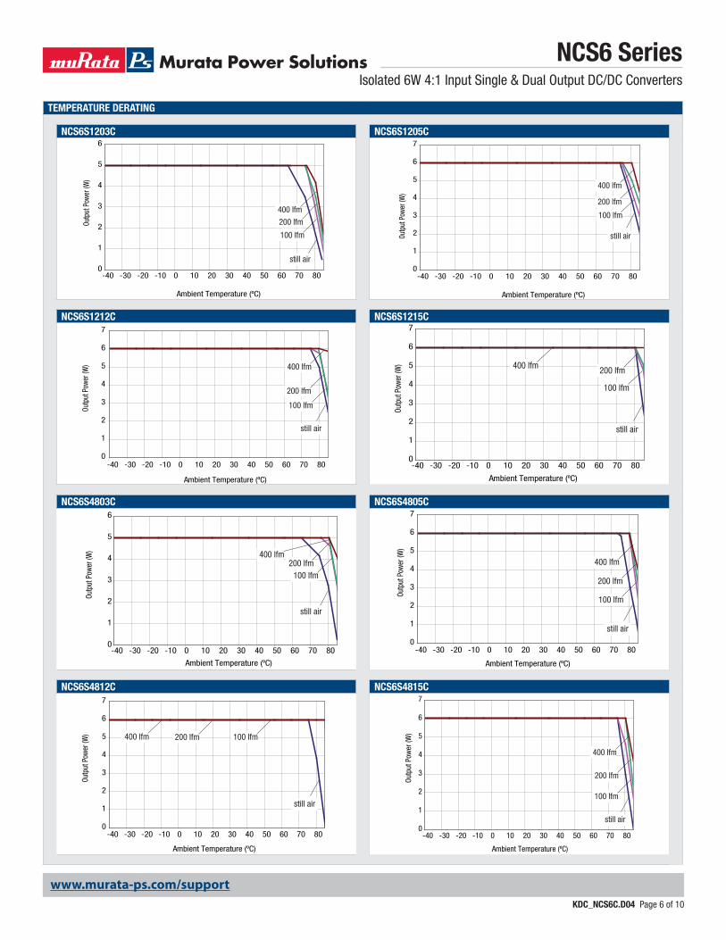
TEMPERATURE DERATING
NCS6S1203C NCS6S1205C
NCS6S1212C NCS6S1215C
NCS6S4803C NCS6S4805C
NCS6S4812C NCS6S4815C
0
1
2
3
4
5
6
7
-40 -30 -20 -10 0 10 20 30 40 50 60 70 80
Ambient Temperature (ºC)
Outp
ut P
ower
(W)
still air
100 lfm
200 lfm
400 lfm
0
1
2
3
4
5
6
7
-40 -30 -20 -10 0 10 20 30 40 50 60 70 80
Ambient Temperature (ºC)
Outp
ut P
ower
(W)
still air
100 lfm
200 lfm
400 lfm
0
1
2
3
4
5
6
7
-40 -30 -20 -10 0 10 20 30 40 50 60 70 80
Ambient Temperature (ºC)
Outp
ut P
ower
(W)
still air
100 lfm
200 lfm400 lfm
0
1
2
3
4
5
6
7
-40 -30 -20 -10 0 10 20 30 40 50 60 70 80
Ambient Temperature (ºC)
Outp
ut P
ower
(W)
still air
100 lfm
200 lfm
400 lfm
0
1
2
3
4
5
6
7
-40 -30 -20 -10 0 10 20 30 40 50 60 70 80
Ambient Temperature (ºC)
Outp
ut P
ower
(W)
still air
100 lfm200 lfm400 lfm
0
1
2
3
4
5
6
7
-40 -30 -20 -10 0 10 20 30 40 50 60 70 80
Ambient Temperature (ºC)
Outp
ut P
ower
(W)
still air
100 lfm
200 lfm
400 lfm
Ambient Temperature (ºC)
0
1
2
3
4
5
6
-40 -30 -20 -10 0 10 20 30 40 50 60 70 80
Outp
ut P
ower
(W)
100 lfm
200 lfm
400 lfm
still air
Ambient Temperature (ºC)
0
1
2
3
4
5
6
-40 -30 -20 -10 0 10 20 30 40 50 60 70 80
Outp
ut P
ower
(W)
100 lfm200 lfm
400 lfm
still air

NCS6 SeriesIsolated 6W 4:1 Input Single & Dual Output DC/DC Converters
KDC_NCS6C.D04 Page 7 of 10
www.murata-ps.com/support
TEMPERATURE DERATING
NCS6D1205C NCS6D1212C
NCS6D1215C NCS6D4805C
NCS6D4812C NCS6D4815C
Ambient Temperature (ºC)
0
1
2
3
4
5
6
7
-40 -30 -20 -10 0 10 20 30 40 50 60 70 80
Outp
ut P
ower
(W)
100 lfm
200 lfm
400 lfm
still air
Ambient Temperature (ºC)
0
1
2
3
4
5
6
7
-40 -30 -20 -10 0 10 20 30 40 50 60 70 80
Outp
ut P
ower
(W)
100 lfm
200 lfm
400 lfm
still air
Ambient Temperature (ºC)
0
1
2
3
4
5
6
7
-40 -30 -20 -10 0 10 20 30 40 50 60 70 80
Outp
ut P
ower
(W)
100 lfm
200 lfm400 lfm
still air
Ambient Temperature (ºC)
0
1
2
3
4
5
6
7
-40 -30 -20 -10 0 10 20 30 40 50 60 70 80
Outp
ut P
ower
(W)
100 lfm
200 lfm
400 lfm
still air
0
1
2
3
4
5
6
7
-40 -30 -20 -10 0 10 20 30 40 50 60 70 80
Ambient Temperature (ºC)
Outp
ut P
ower
(W)
100 lfm
200 lfm
400 lfm
still air
Ambient Temperature (ºC)
0
1
2
3
4
5
6
7
-40 -30 -20 -10 0 10 20 30 40 50 60 70 80
Outp
ut P
ower
(W)
100 lfm
200 lfm
400 lfm
still air
NCS6 SeriesIsolated 6W 4:1 Input Single & Dual Output DC/DC Converters
KDC_NCS6C.D04 Page 8 of 10
www.murata-ps.com/support
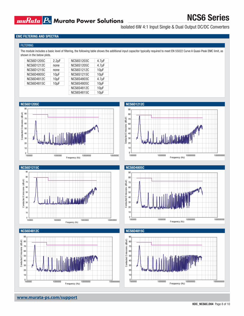
EMC FILTERING AND SPECTRA
FILTERING
The module includes a basic level of filtering, the following table shows the additional input capacitor typically required to meet EN 55022 Curve A Quasi-Peak EMC limit, as shown in the below plots.
NCS6D1205C NCS6D1212C
NCS6D1215C NCS6D4805C
NCS6D4812C NCS6D4815C
0
10
20
30
40
50
60
70
80
90
100000 1000000 10000000 100000000F requency (Hz)
Con
duct
ed E
mis
sion
s (d
BuV
)
NCS6D1205C 2.2µF NCS6S1203C 4.7µFNCS6D1212C none NCS6S1205C 4.7µFNCS6D1215C none NCS6S1212C 10µFNCS6D4805C 10µF NCS6S1215C 10µFNCS6D4812C 10µF NCS6S4803C 4.7µFNCS6D4815C 10µF NCS6S4805C 10µF
NCS6S4812C 10µFNCS6S4815C 10µF
0
10
20
30
40
50
60
70
80
90
100000 1000000 10000000 100000000F requency (Hz)
Cond
ucte
d E
mis
sion
s (d
BuV
)
0
10
20
30
40
50
60
70
80
90
100000 1000000 10000000 100000000F requency (Hz)
Con
duct
ed E
mis
sion
s (d
BuV
)
0
10
20
30
40
50
60
70
80
90
100000 1000000 10000000 100000000F requency (Hz)
Con
duct
ed E
mis
sion
s (d
BuV
)
0
10
20
30
40
50
60
70
80
90
100000 1000000 10000000 100000000F requency (Hz)
Con
duct
ed E
mis
sion
s (d
BuV
)
0
10
20
30
40
50
60
70
80
90
100000 1000000 10000000 100000000F requency (Hz)
Con
duct
ed E
mis
sion
s (d
BuV
)

NCS6 SeriesIsolated 6W 4:1 Input Single & Dual Output DC/DC Converters
KDC_NCS6C.D04 Page 9 of 10
www.murata-ps.com/support
EMC FILTERING AND SPECTRA (continued)
NCS6S1203C NCS6S1205C
NCS6S1212C NCS6S1215C
NCS6S4803C NCS6S4805C
NCS6S4812C NCS6S4815C
0
10
20
30
40
50
60
70
80
90
100000 1000000 10000000 100000000F requency (Hz)
Con
duct
ed E
mis
sion
s (d
BuV
)
0
10
20
30
40
50
60
70
80
90
100000 1000000 10000000 100000000F requency (Hz)
Con
duct
ed E
mis
sion
s (d
BuV
)
0
10
20
30
40
50
60
70
80
90
100000 1000000 10000000 100000000F requency (Hz)
Con
duct
ed E
mis
sion
s (d
BuV
)
0
10
20
30
40
50
60
70
80
90
100000 1000000 10000000 100000000F requency (Hz)
Con
duct
ed E
mis
sion
s (d
BuV
)
0
10
20
30
40
50
60
70
80
90
100000 1000000 10000000 100000000F requency (Hz)
Con
duct
ed E
mis
sion
s (d
BuV
)
0
10
20
30
40
50
60
70
80
90
100000 1000000 10000000 100000000F requency (Hz)
Con
duct
ed E
mis
sion
s (d
BuV
)
0
10
20
30
40
50
60
70
80
90
100000 1000000 10000000 100000000F requency (Hz)
Con
duct
ed E
mis
sion
s (d
BuV
)
0
10
20
30
40
50
60
70
80
90
100000 1000000 10000000 100000000F requency (Hz)
Con
duct
ed E
mis
sion
s (d
BuV
)
NCS6 SeriesIsolated 6W 4:1 Input Single & Dual Output DC/DC Converters
KDC_NCS6C.D04 Page 10 of 10
www.murata-ps.com/support
Murata Power Solutions, Inc. makes no representation that the use of its products in the circuits described herein, or the use of other technical information contained herein, will not infringe upon existing or future patent rights. The descriptions contained herein do not imply the granting of licenses to make, use, or sell equipment constructed in accordance therewith. Specifications are subject to change without notice. © 2013 Murata Power Solutions, Inc.
Murata Power Solutions, Inc. 11 Cabot Boulevard, Mansfield, MA 02048-1151 U.S.A.ISO 9001 and 14001 REGISTERED
This product is subject to the following operating requirements and the Life and Safety Critical Application Sales Policy: Refer to: http://www.murata-ps.com/requirements/
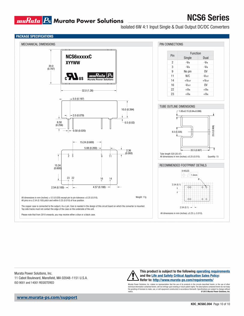
PACKAGE SPECIFICATIONS
MECHANICAL DIMENSIONS PIN CONNECTIONS
PinFunction
Single Dual2 -VIN -VIN
3 -VIN -VIN
9 No pin OV11 N/C -VOUT
14 +VOUT +VOUT
16 -VOUT OV22 +VIN +VIN
23 +VIN +VIN
TUBE OUTLINE DIMENSIONS
RECOMMENDED FOOTPRINT DETAILS
All dimensions in mm (inches) ± 0.5 (0.020) except pin to pin tolerance ±0.25 (0.010).All pins on a 2.54 (0.100) pitch and within 0.25 (0.010) of true position.
The copper case is connected to the output (-VOUT) pin. Care is needed in the design of this circuit board on which the converter is mounted. Top side tracks must not contact the edge of the case on the underside of the unit.
Please note that from 2010 onwards, you may receive either a blue or a black case.
Weight: 17g
All dimensions in mm (inches) ±0.25 (± 0.010).
Tube length 520 (20.47)All dimensions in mm (inches) ±0.25 (0.010). Quantity: 15
0.5 (0.02)
20.0 (0.787)
32.0 (1.26)
XYYWWNCS6xxxxxC
10.0 (0.394)
15.24(0.600)
2.36 (0.093)
2.54 (0.100)
0.50 (0.020)
2.0 (0.079)
5.0 (0.197)
4.57 (0.180)
5.08 (0.200)
15.24 (0.600)
6.50(0.256)
14162223
11932
1.00±0.15 (0.04±0.006)
23.
0 (0
.906
)
8.5 (0.335)
20.5 (0.807)
2.54 (0.1)
Ø
8 HOLES
1.0mm
2.54 (0.1)