ncgmp09-a proposed standard format for digital … · web viewncgmp09—draft standard format for...
TRANSCRIPT

DRAFT -- To be published in DMT'09 Proceedings(see http://ngmdb.usgs.gov/Info/dmt/ )
NCGMP09—Draft Standard Format for Digital Publication of Geologic Maps, Version 1.1
By the USGS National Cooperative Geologic Mapping Program (NCGMP)1
1Prepared on behalf of the NCGMP by members of the National Geologic Map Database Project and the Pacific Northwest Geologic Mapping Project. Contributors (in alphabetical order): Ralph A. Haugerud, Stephen M. Richard, David R. Soller, and Evan E. Thomsemail: [email protected]
NOTE: For the most current version of this document, and for further information including example database and tools, see http://ngmdb.usgs.gov/Info/standards/NCGMP09/.
INTRODUCTION
This document proposes a standard format for geologic map publications funded by the Na-tional Cooperative Geologic Mapping Program (NCGMP) of the U.S. Geological Survey. This format, or database design, is named NCGMP09 to reflect the initial audience. We hope that this design will adapt to evolving needs and expectations, and meet the needs of a larger community of users. NCGMP09 was introduced at the Digital Mapping Techniques ’09 meeting (May 2009), as version 0.8.2, in order to solicit preliminary comments and testing. Version 1.0 was released October 14, 2009, for presentation at the Geological Society of America’s Annual Meeting. In the months following, more extensive evaluations were received, and in response the design evolved. The document in these Proceedings reflects the current manifestation of NCGMP09 (version 1.1). For those readers interested in comparing earlier versions, these are archived at http://ngmdb.usgs.gov/Info/standards/NCGMP09/. We and an extended group of colleagues will continue to revise the design based on comments re-ceived, and we intend to release a revised version under a new name in 2011.
NCGMP09 is a database design for encoding content analogous to that contained in a traditional geologic map published by the USGS and by State geological surveys. It stipulates an ESRI database format in order to adhere to USGS policy1 and because this is the GIS most commonly used in the USGS, in the State geological surveys, and in the larger community. Migration to a nonproprietary for-mat, such as the GML-based GeoSciML, is a worthy goal, and the database is designed with this in mind.
This design is intended to provide a stepping stone toward development of multi-map databases, in particular the National Geologic Map Database (NGMDB). The NGMDB Project assists with coor-dination of database design work between the USGS and State geological surveys, and is mandated to build a national archive of standardized geologic map information. The database design proposed herein will significantly promote that goal.
1 General policy stated in Section 6.1.3 (USGS-only link at http://geology.usgs.gov/usgs/policy/policy6.shtml), supplemented May 24, 1999, by details shown at http://ngmdb.usgs.gov/Info/standards/dataexch/USGSpolicy.html (see section 3, but disregard reference to SDTS, which no longer is applicable).
1

DRAFT -- To be published in DMT'09 Proceedings(see http://ngmdb.usgs.gov/Info/dmt/ )
In our years of work prior to defining NCGMP09, we learned that a single database design can-not (yet?) suit all purposes. This lesson has been underscored by our colleagues’ evaluations of this de-sign. A database most suited to the needs of a field geologist will likely not address the content and cartographic requirements of a single-map database that is intended to be published and then used by geologists and nongeologists, nor the requirements of a multi-map database maintained in perpetuity by a mapping agency. We further recognize that even for one of these purposes a single design may be contentious, in part owing to varying requirements (e.g., for field systems, requirements imposed by lo-cal geology or particular hardware). We have pragmatically developed a design that should prove gen-erally useful, recognizing that many will not find it their first and best choice. Compromise in design, without sacrificing the flexibility necessary for science-driven information management, is the path we have sought during development of this standard.
ObjectiveGeologic mappers, geologic mapping agencies, and geologic map users would benefit from a
standard database design for digital representation of geologic maps. This document proposes such a design for the representation of a single geologic map. The design is focused on the transfer and ar-chiving of map data, with less emphasis on the creation of map data, the visual representation of map data, or the compilation of data from many maps. With increased use of this design we anticipate re-ductions in the cost of map production and publication (data compilation and synthesis, review, editing, cartography, pre-press, training, and tool development).
We focus on the representation of a single map for two reasons: this is the issue the geologic community (and our workgroup) understands best, and this is the problem that we perceive is most in need of a solution. The construction and maintenance of an enterprise, multi-map database brings sev-eral issues that we do not here address, including versioning, multiple-scale representations, vocabulary management, maintenance of the stratigraphic lexicon, and access control.
For the purposes of this design, ‘single geologic map’ means a package of data (bearing in mind that many geologic ‘data’ are inherently interpretations) that pertains to a single portrayal of the geol-ogy of some area (the map extent), directly analogous to the traditional paper geologic map. While this package may include different views of the data—e.g., the principal map view, one or more cross sec-tions, perhaps one or more detail maps—each view is represented by a unique mapping between the data and symbols (graphical elements). As a publishable product similar to a conventional geologic map, the database package is attributed to an author or authors who have either collected original data and developed the data package and portrayal or have compiled data from existing sources and devel-oped the portrayal.
This document is intended to bridge between geologic mapping and GIS communities at an op-erational level. We are codifying lessons from our experience and we expect that this document will be successful largely to the extent that it tells its readers what they already know.
Lessons learned in the last two decadesGeologic map data producers have been developing and using GIS representations of geologic
maps for more than two decades. In the course of this effort we have all learned some lessons.
2

DRAFT -- To be published in DMT'09 Proceedings(see http://ngmdb.usgs.gov/Info/dmt/ )
The distinction between map data and its symbolization is important. Maps can be represented digitally by scanning them and storing the image file, but this is a very small step towards making the map more useful and its constituent data more easily used for various purposes. Similarly, maps should be more than vector graphic files (e.g., in Adobe Illustrator format). Map data are most usefully stored and analyzed in a geographic information system (GIS), with feature locations given in a real-world spatial reference framework (e.g., UTM10, NAD83) and feature attributes stored explicitly in database tables (e.g., line number 27 is an accurately located thrust fault, line 28 is an approximately located contact, line 29 is the shoreline of Lake Erie on Aug. 27, 1978). A map image, composed of lines, col-ored areas, patterns, and markers, is a symbolization of the data contained in the database, analogous to a tabular report based on financial data in an accounting database.
Maps need metadata for the overall dataset and for individual elements. Early GIS practices, largely stemming from limitations of storage space and database architecture, as well as paper-map precedent, led to the creation of a significant number of databases in which key fields were populated with symbols (e.g., map unit = Ks) and these symbols were not defined within the database. This is in-adequate. Most geologic maps have mixed origins and data qualities; map users benefit from feature-level metadata that describes data source and quality. Map data should be closely linked to authorship because maps are interpretations made by individuals or workgroups, and linked to sponsoring entities because most maps could not be made without significant support from a governmental agency, aca-demic institution, professional society, or private industry.
Real-world database designs reflect compromises between the intrinsic complexity of geologic map data, the needs of geologists and GIS practitioners who work with the design, the capabilities of GIS and database software, and the limitations of the underlying computer operating system and hard-ware. Database designs that do not make such compromises are unlikely to be widely used. Even the names of data entities (e.g., of spatial feature sets, tables, fields) must be carefully crafted to be readily understood by users with different backgrounds, to facilitate adaptation and re-use of software tools, and to promote distribution, translation, and compilation of data.
It is difficult to obtain community acceptance for data architecture (tables and spatial feature sets), data attributes, attribute names, and attribute vocabularies that extend beyond the precedents set by our paper mapping tradition. This conservatism is a good thing because our paper map tradition embodies a great deal of hard-won wisdom. But it is also unfortunate because our tradition reflects compromises necessitated by the limitations of the paper map format.
There is also a widely shared perception that paper geologic maps, with their subtleties of layout, sometimes carefully ambiguous descriptions, and textual and visual vocabularies that are often opaque to the uninitiated, are not readily used by the public that needs (and pays for) the information contained within these maps. We hope this proposed design contributes to a better understanding and wider use of geologic map data.
Acknowledgments
This database design is an outcome of years of research and collaboration by many scientists and GIS specialists, under auspices of numerous projects and initiatives. We gratefully acknowledge what we have learned from them, and hope this draft design sufficiently meets with their approval to warrant comment and improvement. In particular, we thank Peter Lyttle (Program Coordinator, National Coop-erative Geologic Mapping Program) for his recommendation in 2008 that we undertake this work. We also thank our many colleagues who have given thoughtful comments and critiques of this design.
3

DRAFT -- To be published in DMT'09 Proceedings(see http://ngmdb.usgs.gov/Info/dmt/ )
CONTENTS
As an aid to comprehension, the content headings are provided here:
INTRODUCTIONo Objective
o Lessons learned in the last two decades
o Acknowledgments
CONTENTS REVIEW, COMMENT, AND REVISION DESIGN CONSIDERATIONS
o Content of a traditional geologic map
o Extensions to traditional geologic map content
Feature-level metadata Glossary General Lithology
o Naming database elements
o Transparent identifiers
o Open file formats
REQUIRED, AS-NEEDED, AND OPTIONAL CONTENTS OF A DIGITAL GEOLOGIC MAP PUBLICATION
THE GEODATABASE DESIGNo General considerations
This design implies a relational database Type, Label, and Symbol fields Polygons, lines, and topology: what goes where? Directional lines
o Required elements
GeologicMap (feature dataset) MapUnitPolys (polygon feature class) ContactsAndFaults (line feature class) DataSourcePolys (polygon feature class)
DescriptionOfMapUnits (non-spatial table)
4

DRAFT -- To be published in DMT'09 Proceedings(see http://ngmdb.usgs.gov/Info/dmt/ )
DataSources (non-spatial table) Glossary (non-spatial table)
o As-needed elements
Guidelines for naming and designing additional polygon, line, and point feature classes
Structure of point data Point feature classes: general
Some examples of as-needed feature classes OrientationPoints (point feature class) GeochronPoints (point feature class) Stations (point feature class) GeologicLines (line feature class) CartographicLines (line feature class) IsoValueLines (line feature class) OtherPolys (polygon feature class)
RepurposedSymbols (non-spatial table) SYMBOLIZATION SHAPEFILE VERSIONS OF THE GEODATABASE
o Simple version
o Open version
APPENDIX A. LITHOLOGY AND CONFIDENCE TERMS FOR GENERALLITHOLOGYo GeneralLithology
o GeneralLithologyConfidence
APPENDIX B. OPTIONAL ELEMENTS Cross Sections (feature datasets) Correlation of Map Units (feature dataset)
CMUMapUnitPolys (polygon feature class) CMULines (line feature class) CMUText (annotation feature class) CMUPoints (point feature class)
ExtendedAttributes (non-spatial table) GeologicEvents (non-spatial table) StandardLithology (non-spatial table)
APPENDIX C. BUILDING A COMPLIANT DATABASEo Additional database elements
5

DRAFT -- To be published in DMT'09 Proceedings(see http://ngmdb.usgs.gov/Info/dmt/ )
MapUnitPoints (point feature class, optional) ChangeLog (non-spatial table, optional)
o Suggestions regarding workflow
Attributing ContactsAndFaults Splitting lines to localize ornament (e.g., bar-and-ball on normal fault) is bad
practice Building MapUnitPolys DescriptionOfMapUnits table and DMU text Formal metadata Encoding additional information
APPENDIX D. FREQUENTLY ASKED QUESTIONS
REVIEW, COMMENT, AND REVISIONWe seek a database design that has broad support from the geologic mapping community. There-
fore, we ask that you review it and provide comment in order to, collectively, improve the database de-sign, the documentation that explains it, and the tools and templates that facilitate its use. Please con-tact us via email, at [email protected].
Regarding availability and maintenance of this database design, under the authority of the Geo-logic Mapping Act of 1992 (and subsequent reauthorizations), the National Geologic Map Database Project will function on behalf of the NCGMP as coordinator of database design changes and mainte-nance. This activity will be conducted in cooperation with NCGMP projects and other identified stake-holders (e.g., the Association of American State Geologists).
DESIGN CONSIDERATIONSWe have attempted to:
Encode all the content of a traditional paper geologic map.
Focus on the digital storage and transfer of a single geologic map. Facilitate interactive display and query. Provide a foundation for publication-quality visualization. Do not here try to solve the multi-map database problem.
Define the names and types of all constituent elements in order to meet user needs for consis-tency and to facilitate re-use of code and tools by map-producers. Use names that have obvious meaning to geologist and GIS practitioners alike.
Address the persistent perception that traditional geologic maps do not meet the public’s (and
6

DRAFT -- To be published in DMT'09 Proceedings(see http://ngmdb.usgs.gov/Info/dmt/ )
the scientist’s) need for consistently named and defined earth materials data, by beginning to in-troduce standard terms and definitions, which may be extended in future revisions.
Preserve, and facilitate the analysis of, map topology.
Normalize map data for robustness and compactness of the database, but not to the extent that user comprehension is reduced.
Allow queryable description of map features with as much (or as little) granularity as desired.
For flexibility, interoperability, and data longevity, strive toward use of open file formats.
Content of a traditional geologic mapTraditional geologic maps have rich semantic content that should be preserved in the digital publi-
cation. This content is outlined below. Yellow background denotes content for which we do not specify a digital form.
1. Map graphic1. Base map2. Map-unit polygons (polygons that cover the mapped area with no voids and no overlaps.
May include open water, permanent snowfields and glaciers, and unmapped areas).3. Contacts and faults that, with a few exceptions, bound and separate map-unit polygons.4. Several elements that are present as needed to portray the content of a particular map:
1. Overlay polygons, e.g., alteration zones, perhaps extensive artificial fill, surface projection of mined-out areas. Note that while these polygons commonly repre-sent features that are within, or beneath, the rocks and deposits represented by map-unit polygons, they are commonly represented on the map as patterned overlays.
2. Other lines, including traces of fold hinges, facies boundaries, isograds, cross-section lines, dikes and sills, marker beds, structure contours, etc. In general, overlay polygons and other lines do not conform to the strict topological rules that constrain map-unit polygons and contacts and faults (no polygon voids or overlaps, contacts lie on polygon boundaries, faults may dangle but contacts may not).
3. Point data, which may include (but are not limited to) structural data (orientation measurements: axes and vectors), sample locations, geochronologic results, fos-sils, chemical analyses, prospect locations, displacement (fault-slip) measure-ments, and points for map-unit polygons too small to show at scale.
2. Zero to many cross sections (each with elements analogous to map elements, except that the base map is replaced by a topographic profile).
3. Correlation of Map Units diagram (“CMU”) that includes unit designators, brackets, dividing lines, and text.
4. Symbolization for above, including:1. Map-unit area fills (color and optional pattern)2. Patterns for overlay polygons3. Line symbols and (or) point markers for map-unit areas too small to show as polygons
at map scale
7

DRAFT -- To be published in DMT'09 Proceedings(see http://ngmdb.usgs.gov/Info/dmt/ )
4. Text tags for some (but not necessarily all) polygons5. Leaders for text tags for some polygons6. Line symbols (with variable color, weight, dot-dash pattern, repeated marker ornament,
etc.) for some lines7. Text labels for some lines and groups of lines8. Point (marker and (or) text) ornaments for some linear features9. Markers and (or) text for some point data10. Leaders for markers and (or) text for some point data.
5. Description of Map Units (DMU) or List of Map Units with descriptions in an accompanying pamphlet. Traditionally, the DMU does not describe water, permanent snow and glaciers, un-mapped area, and some overlays and underlays, but does include headings and some units not shown on the map (e.g. Group or Formation which is entirely mapped as constituent sub-units). DMUs are strongly hierarchical. Each unit shown on the map has area-fill color and pattern, tag, unit name, age, description, position in hierarchy, and a paragraph style that (in part) de-notes position in hierarchy. Headings and units not shown on the map lack area fill color and pattern and tag.
6. Explanation of line symbols7. Explanation of point symbols8. Miscellaneous map collar material. Includes report title, author(s), date of publication, pub-
lisher, series and series number, mapped-by statement, edited-by statement, cartography-by statement, specification of spatial reference framework, and scale.
9. Zero to many figures10. Zero to many tables11. Zero to many additional maps (e.g., sources of map data; distribution of facies in the Cambrian)12. Extended text, as needed13. References Cited, as needed.
Extensions to traditional geologic map contentWe include several extensions to traditional geologic map content. Three are required: feature-
level metadata, an internal dictionary that replaces some of the detailed descriptions of entities and at-tributes in report-level metadata, and categorization of map-unit lithology using a standard scheme. Optional extensions are supplemental standardized lithologic descriptions of map units, extended at-tributes to add additional properties, and structured, more detailed descriptions of the ages of geologic events; these may be used to store content that otherwise might be stored in extended text, tables, or figures.
Feature-level metadata
All elements of a geologic map database should be accompanied by an explicit record of the data source. Many elements should also have explicit statements of scientific confidence—for exam-ple, how confident is the author that a feature exists? Or that it is correctly identified? How confi-dently are feature attributes known? These are challenging questions to which the field geologist may not be comfortable providing an answer, except in the most general sense. We recognize this. But we also recognize that geologic information commonly is used in a GIS, in conjunction with other types of information (e.g., cadastral surveys, road networks, pipelines), and that terms such as “accurately lo-
8

DRAFT -- To be published in DMT'09 Proceedings(see http://ngmdb.usgs.gov/Info/dmt/ )
cated” have a markedly different meaning for a pipeline or property line than for a geologic contact. Thus in order to provide a general indication of the confidence and locational accuracy of geologic-map features, we implement per-feature descriptions of scientific confidence and locational accuracy. For more discussion of this topic, please see Section 4 of the FGDC Digital Cartographic Standard for Geologic Map Symbolization, FGDC-STD-013-2006, http://ngmdb.usgs.gov/fgdc_gds/.
In some cases, default confidence and locational accuracy values for an entire map are appropri-ate. Although default values may seem meaningless, changes in default values from map to adjacent maps are likely to be informative to map users. As software tools evolve, we expect to see changing work flows that produce more detailed metadata.
Data source (provenance). Typically, a single map database will have very few data source records, as many features will have identical sources. For a database composed entirely of new map-ping, there could be a single data source: “this report”. Some data elements have compound sources: geochemical analysis of a rock sample will typically have one source for the map location and strati-graphic provenance of the sample (the field geologist) and another source for the chemical analysis (the geochemist). In such cases, multiple source fields in the relevant data table are appropriate, e.g., Loca-tionSource and AnalysisSource.
Location confidence (spatial accuracy). Reported locations of geologic features commonly are uncertain. This may be because of error in locating observation points (because of, for example, GPS error or an imprecise base map), or because features are subtle and difficult to locate, or because the lo-cations of features are known by inference from the locations of other observations. Such uncertainty could be expressed as uncertainty in absolute location (that is, geodetic accuracy). However, because most users locate geologic features in relation to an associated base map, and because most spatial analyses of geologic map data are in relation to the base map or to other data in the same database, we choose to focus on location confidence relative to features on the base map and to other data in the geo-database. We define location confidence (database field LocationConfidenceMeters) as the combina-tion of error in positioning of observed features or known positions relative to the base map and the un-certainty in location of a feature relative to a known position (i.e., how precisely, relative to where I am standing, can this contact be placed?). For a well-exposed sharp contact, the second factor is zero and location confidence becomes equivalent to positioning error.
This usage differs from that advocated by section 4.2 of the FGDC standard, which suggests that spatial accuracy be expressed as three attributes: (1) locatability (with values of observable, in-ferred, or concealed); (2) zone of confidence (a distance, perhaps equivalent to 1/25th of an inch at map scale; may be the same for all parts of a map or may vary spatially); and (3) positioning (with values of within zone of confidence or may not be within zone of confidence). We depart from the FGDC recom-mendation in order to create databases that are less dependent upon visualization scale, more informa-tive (if a feature is not positioned within the zone of confidence, the FGDC recommendation provides no way to record any quantitative knowledge of how well located the feature is), simpler, and more comprehensible.
LocationConfidenceMeters should be reported as the estimated radius (in meters) of the circle of uncertainty about a point location, or the half-width (in meters) of the zone within which a line is as-serted to be located. Values commonly will not be known precisely. This is acceptable. Even with a factor-of-two uncertainty, author-assigned values of LocationConfidenceMeters are preferable to an un-reported value or a value assigned by a third party. The positions of certain lines (e.g., map boundaries) commonly are calculated, not observed; for these lines, positional uncertainty has little meaning and LocationConfidenceMeters should be assigned a value of 0.0. For some digital transcriptions of legacy
9

DRAFT -- To be published in DMT'09 Proceedings(see http://ngmdb.usgs.gov/Info/dmt/ )
paper geologic maps, it may not be possible for the transcriber to assign an approximate value to Loca-tionConfidenceMeters. In these cases, a negative value (e.g., -9) may be used to indicate “unspeci-fied”.
Existence confidence, identity confidence, and scientific confidence. The FGDC Standard notes that scientific confidence may have multiple dimensions. For a map unit area, scientific confidence has one dimension: confidence that the map unit is correctly identified. In the case of faults, contacts, and other feature traces, the situation is more complex. There may be uncertainty as to whether a boundary between two units is a contact or fault. There may be uncertainty as to what kind of fault is mapped. In both cases, this uncertainty is specified by an identity confidence value. In some cases, the presence of a fault may be suspected but is not certain. Fold hinge surface traces, dikes, and marker beds may also be mapped where their existence is suspected but not certain. This uncertainty is specified by ex-istence confidence. Contacts are rarely mapped where their existence is uncertain; if different map units are identified, there must be a boundary of some sort between them, in which case the identity of that boundary may be questionable, but not its existence.
NCGMP09 includes ExistenceConfidence and IdentityConfidence for line feature classes, and IdentityConfidence for polygon and point observation features. We discussed at length whether to combine these confidence concepts into a single ScientificConfidence field in the database, perhaps with 4 or 6 values to allow for various combinations of existence and identity confidence, but decided that it makes more sense to leave both as separate fields, as specified in the FGDC Standard. We ex-pect that symbolization will in some cases be assigned on the basis of feature type and the appropriate confidence terms. As noted above, in many situations default values for the entire map area are appro-priate; in situations, tools to efficiently assign confidence values can be developed.
For most databases we expect that all ExistenceConfidence and IdentityConfidence values will be either “certain” or “questionable,” though this Standard allows other values (which must be de-fined). For some digital transcriptions of legacy paper geologic maps, it may not be possible for the transcriber to assign values of ExistenceConfidence or IdentityConfidence, and these may be coded as “unspecified.” Appearance of such values in a database of new mapping should raise a red flag during the review process.
Orientation confidence. For measurements of rock structures (bedding, foliation, lineation, joints, etc.) it is useful to describe how accurately the orientation has been measured. This is specified as the circular error of a direction (for planar features, of the pole to the plane), which is most usefully expressed as an angular measure (of the radius of the error circle) similar to the alpha95 value often re-ported for paleomagnetic directions. The OrientationPoints feature class includes an OrientationConfi-denceDegrees field to record this uncertainty.
Glossary
Many digital geologic map databases (and many published paper geologic maps) have provided definitions for few, if any, of the technical terms used to name and describe map features. A few pro-ducers of geologic map databases have remedied this with formal metadata that contains definitions and definition sources for elements of enumerated value domains within detailed entity and attribute descriptions. Such definitions and definition sources, unfortunately, can be difficult to access and nearly impossible to relate automatically to the relevant features in the database. We implement a Glossary table that, for certain fields, lists the terms that populate these fields, term definitions, and sources for definitions. Definitions and definition sources are readily accessed with a standard relate
10

DRAFT -- To be published in DMT'09 Proceedings(see http://ngmdb.usgs.gov/Info/dmt/ )
based on the term field. Formal metadata, in the overview description of a feature class or table, could reference the Glossary table for definitions and definition sources; listing of definitions and sources within detailed entity and attribute descriptions is not necessary.
Terminology used in the database must be defined in this Glossary. If this seems excessively la-borious, consider that if terms are defined in this Glossary they (1) are more readily available for dis-play on-screen within the map; (2) can be more easily searched and extracted for other publications; and (3) can be used as sources for data-driven products such as metadata.
Creation of the Glossary table should not be an undue burden on the database producer. In most cases, definitions copied or paraphrased from standard sources (e.g., AGI Glossary of Geology, with appropriate attribution) will be appropriate. Terms used only in the Description field of the Descrip-tionOfMapUnits table (defined below) need not be defined. We expect that building Glossary tables for the first few reports produced by a workgroup will be a significant effort. Subsequent Glossaries should be much easier to develop, as a prior Glossary can be recycled with minor amendments and up-dated DefinitionSourceIDs.
General Lithology
The traditional Description of Map Units conveys essential information about each map unit. As such, it is a cornerstone of the NCGMP09 design. However, these descriptions vary in their content and format and commonly use specialized terminology that is unfamiliar to the non-geologist. Termi-nology may, for valid reasons, be used inconsistently from map to map. For these and other reasons, many classifications have been devised in attempts to organize and standardize descriptions of geologic map units, improve our ability to make regional compilation maps, and better convey geologic infor-mation to the public. Of necessity such classifications are compromises that only partially describe the near-infinity of map-unit compositions, textures, genesis, and appearance.
The North American Data Model Steering Committee (http://nadm-geo.org/), sponsored by USGS, AASG, and the Geological Survey of Canada, defined a general, conceptual data model for geo-logic maps and a “Science Language” for describing various characteristics of earth materials. The summary report on science language is available at http://pubs.usgs.gov/of/2004/1451/nadm/in-dex.html. The classifications presented in that report have been evaluated and adapted for many pur-poses; for example, the IUGS-CGI Geoscience Concept Definitions Working Group has incorporated that work into a limited set of lithology categories (“SimpleLithology”) for use in GeoSciML inter-change documents (see https://www.seegrid.csiro.au/twiki/bin/view/CGIModel/ConceptDefinition-sTG).
A similar list of terms, known as “StandardLithology” accompanied the initial release of NCGMP09 (version 1.0). The StandardLithology term list and GeoSciML’s SimpleLithology were de-signed to be used with a ProportionTerm list to encode the numerous lithologies found in each map unit and their relative proportions. This approach encourages multiple entries for each map unit, thereby al-lowing description of map units in some detail. StandardLithology was received with little enthusiasm by many of the reviewers of version 1.0.
We remain convinced that standardized map unit descriptions are beneficial, largely because of their potential to:
1) Facilitate queries for the presence of a particular rock type. Using a hierarchical classification, both the queried rock type and all rocks related to it can be found (e.g., if “volcanic rock” is
11

DRAFT -- To be published in DMT'09 Proceedings(see http://ngmdb.usgs.gov/Info/dmt/ )
queried, “basalt” also is returned).
2) Allow more-uniform portrayal of lithology across multiple maps.
3) Focus the geologic-mapping community on the generally held notion that standard classifica-tions are useful. What should these classifications contain, and what is their purpose?
Bearing in mind the importance of giving the public a simple and systematic view of the Nation’s geology, we include in NCGMP09 a simplified classification based on general lithologic and genetic character. This classification, GeneralLithology, applies a single term to each map unit, providing in-formation that a non-expert can quickly use to identify map units that contain similar materials. We recognize that from the field geologist’s perspective a single standard classification cannot adequately address the geology of a given region in sufficient detail. Therefore, we also encourage more detailed descriptions of the distinct geologic materials that occur within map units using the optional Standard-Lithology table, as described in Appendix B.
The GeneralLithology term list now included in NCGMP09 was developed for the NGMDB Data Portal, a prototype site (ca. 2008) intended to raise discussion with NGMDB partners in the state geo-logical surveys regarding how to provide the public with an integrated view of regional-scale geologic maps, with links to the source map information. The term list and associated confidence terms are given in Appendix A. Documentation of the term list, including rationale, is provided in Soller (2009; http://pubs.usgs.gov/of/2009/1298/pdf/usgs_of2009-1298_soller4.pdf).
Is GeneralLithology (and StandardLithology as well) adequate and appropriate for the intended use? As implied in item 3 above, the process of developing such lists is iterative: although the commu-nity has already devoted significant effort to standardizing terminology for map-unit lithology, this work needs to continue. Discussion will be most effective after a term list has been evaluated by appli-cation to geologic map databases that are being prepared for publication. It is important to bear in mind that the NCMGP09 database is focused on data delivery to the public. Scientists engaged in geo-logic field research may wish to have more detailed, structured terminology in their research databases than is possible with the NCGMP09 schema or the GeneralLithology and StandardLithology vocabu-laries. For those scientists and their mapping projects, evaluation of the salary and programming costs versus the research and societal benefits of implementing supplemental data structures and vocabular-ies may indicate that the NCGMP09 schema should be extended in order to create more precisely con-strained, controlled-term descriptors. If this is found necessary, please refer to the method noted for StandardLithology, in Appendix B.
We anticipate that evaluation by map producers (i.e., geologists) and end users will cause the NCGMP09 terminology lists to be revised. Revisions will be posted to http://ngmdb.usgs.gov/Info/standards/NCGMP09/. We will solicit comments in group discussions (e.g., with mapping projects and agencies, and at Digital Mapping Techniques meetings). We also request that individuals send com-ment to us at [email protected]. Of immediate concern are: What specific difficulties have been encountered in attributing map units with GeneralLithology? How does the term list need to be revised? In the longer term, comments on effectiveness of these controlled-term lists for geologic analyses, or compilation efforts, also are welcomed. Please bear in mind that GeneralLithology is not intended to supplant more detailed and precise lithologic terminology used in the Description of Map Units text or in more detailed and specialized controlled-term lists.
12

DRAFT -- To be published in DMT'09 Proceedings(see http://ngmdb.usgs.gov/Info/dmt/ )
Naming database elementsFixed, easy-to-comprehend names for all elements are key to a functional geodatabase design.
Names have been chosen according to the following criteria:
Names convey content to the geoscientist, to the GIS practitioner, and to the public Names use uniform concatenation protocol (CamelCase, the first letter of each word is in
upper case) Names do not exploit case sensitivity. Note that case should be conserved, as some lan-
guages and operating systems distinguish between ThisName and thisName Names do not contain spaces or special characters Long names are acceptable and informative Names are easy to code and calculate Names reflect data type Names point to related tables. Field names which contain “SourceID” are reserved for for-
eign keys to table DataSources Field names which contain “_ID” are reserved for primary keys. These are of the form
TableName_ID or FeatureClassName_ID. These primary keys are maintained by the data-base creator, not the GIS software, and are used mostly to relate attributes stored in non-spa-tial tables to spatial features, and—optionally—to relate spatial features to additional, fea-ture-specific attributes stored in tables ExtendedAttributes and GeologicEvents.
We have chosen not to encode the publication identity (map name or map series number) in the names of feature datasets and feature classes. Feature dataset and feature class names that include a map identifier (name or series number) would simplify the joint display of multiple publications in an ArcMap project because each layer name automatically includes the map identifier for the layer. Our choice to use the same name for feature datasets and feature classes in all delivery databases keeps the naming scheme simple and facilitates the coding and sharing of tools to manipulate geodatabases. Users who create ArcMap projects that reference multiple databases may find it convenient to manually update the names of layers to reflect their map sources.
Transparent identifiersIdentifiers in the database for map units, line types, and point feature types should have obvious
plain-English meaning. The map unit identifier is used as a foreign key from the DMU table to various other tables, and this should be the unique label used to identify that unit in map displays. Entries in the DMU that are not symbolized on the map may have null map unit identifier values. The type iden-tifiers for lines and points are references to terms in the Glossary, and we recommend that these simply be the geologic term for the line or point type represented. This is in contrast to common practice which dictates that identifiers used as foreign keys in a database are best implemented as numbers or text string that have no inherent meaning to users; these commonly are referred to as opaque identifiers. Though opaque identifiers may be more robust, we think that for a delivery database this advantage is outweighed by the greater intelligibility for people gained by using human-interpretable identifiers. Note that this specification does not prohibit the use of opaque identifiers, particularly for primary key (table_ID) values.
13

DRAFT -- To be published in DMT'09 Proceedings(see http://ngmdb.usgs.gov/Info/dmt/ )
Open file formatsIn principle, we encourage the use of open file formats, because: (1) open formats facilitate
writing and redistribution of third-party code; (2) open formats reduce the risk of locking data up in formats that become obsolete and unreadable – when open formats are superseded, documentation for them is likely to remain available; and (3) open formats are likely to change in a more measured fash-ion than proprietary formats. Many in the geologic mapping community are still coping with the costs of the relatively rapid transitions from coverages to shapefiles and from shapefiles to geodatabases.
Text should be stored as .txt, .html, .odt (Open Document Format, ISO/IEC 26300:2006 or its successor), or .pdf files. The patent on LZW compression (commonly used in .tif or .gif images) has expired and patents that may have restricted the use of JPEG compression (.jpg images) have been found invalid, thus the choice between .png, .tif, .jpg, and .gif files for raster images should depend on technical considerations. Vector, or mixed vector-raster, images should be stored as .pdf or .svg files. Tables may be stored as .dbf files, for which there appears to be no published standard but for which documentation is readily available, or as .xml files which most modern database software can import.
Our desire to endorse open file formats is overshadowed by our need to prescribe a database file format that preserves topology, allows long attribute names, and works well within ArcGIS, thus we specify the use of ESRI’s personal geodatabase (.mdb) or file geodatabase (.gdb) file formats for spatial data. To make geologic map data more widely available, we require that data also be released in shape-file formats (see below). We look forward to wider implementation and use of text-based, application-independent delivery formats such as GeoSciML.
REQUIRED, AS-NEEDED, AND OPTIONAL CONTENTS OF A DIGITAL GEOLOGIC MAP PUBLICATION
For a map publication named mapXYZ, the publication package should include the files described below. Note that “as needed” elements must be present if they are appropriate to the content of the map publication, e.g., if there is a Figure 1 in the map publication, then a file Figure1.png (or equivalent) must be present in the digital product. “Optional” elements may or may not be present at the discretion of the author or publisher. Required elements are highlighted in pale red; as-needed elements are highlighted in pale gray.
mapXYZ.pdf Reference map visualization. Publication quality
mapXYZ-browse.png (.jpg, .tif) Browse graphic. A small file
mapXYZ-pamphlet.pdf Map pamphlet, as needed
mapXYZ-metadata.xml FGDC metadata. More-or-less human-readable metadata files (.txt, .html) are optional
mapXYZ-gdb.zip When unzipped, this file contains:
mapXYZ.gdb (file geodatabase folder) or mapXYZ.mdb (personal geodatabase file)
14
DRAFT -- To be published in DMT'09 Proceedings(see http://ngmdb.usgs.gov/Info/dmt/ )
mapXYZ.mxd ArcMap document stored with relative pathnames and including relevant macros
mapXYZ.pmf ArcReader document
resources (folder)
figures (.png, .pdf, .tif) As needed
tables (.dbf, .ods, .xls) As needed
CMU (.pdf, .png, …) Optional. Graphic representation of correlation of map units dia-gram. Note: eventually this will be superseded by required encod-ing of CMU within the map geodatabase
DMU (.pdf) Optional. Additional document for description of map units
mapXYZ.style ArcGIS style file for area, line and marker symbols used in pre-ferred symbolization of map. Will be largely a subset of the FGDC geology symbol set. Please see the NCGMP09 Web site for a sug-gested master style file and associated font files. Must include all symbols specified elsewhere in database. Include any non-stan-dard font files referenced by the style file. Unnecessary if appro-priate cartographic representations are included in the geo-database itself
mapXYZ-pamphlet.pdf Map pamphlet, as needed
base.gdb or base.mdb (folder or file) As needed; required if base-map geospatial data are not published elsewhere. Otherwise optional
mapXYZ-metadata.xml FGDC metadata; copy of file referenced above
mapXYZ-simple.zip Simple version of database. See below for contents
mapXYZ-open.zip Open version of database. See below for contents
THE GEODATABASE DESIGNThere are required, as-needed, and optional elements in this single-map geologic map geo-
database (Figure 1). Required and as-needed elements are specified below. Optional elements are de-scribed in Appendix B. For each element (feature dataset, feature class, non-spatial table) we provide a name, identify the element type, and enumerate the fields (attributes) in the relevant table. Unless oth-erwise noted, all fields are of data type text (= string). Any length is appropriate, so long as it is suffi-cient to store the associated values; we recommend 50 characters for ID fields and 255 characters for most other fields. For each field we briefly discuss content and domains where appropriate. For some elements, this is followed by a short example table and further discussion.
15

DRAFT -- To be published in DMT'09 Proceedings(see http://ngmdb.usgs.gov/Info/dmt/ )
Figure 1. ArcCatalog view of NCGMP09-style geodatabase, showing required, as-needed, and optional database components. As-needed elements must be present if they are appropriate to the content of the map publication. Optional elements may or may not be present at the discretion of the author or publisher. There may be more than one cross-section feature dataset, named CrossSectionA, CrossSectionB, etc.
The values in certain fields must be defined in the Glossary table or a referenced external data dictionary. Such fields are shown with cyan backgrounds below.
Every feature class and table has a primary key field with a name of the form <TableName_ID>. Where values of this primary key populate a field in another feature class or table, that field has a different name. For example, values of DataSources_ID populate fields named Descrip-tionSourceID (DescriptionOfMapUnits) and LocationSourceID (point data tables) and DataSourceID (many tables).
If data loaded into a database do not already have user-managed primary keys, we suggest that primary key values be created from a three- or six-letter prefix based on the name of the containing ta-ble concatenated with an integer suffix unique to the containing table. The suffix could be the string representation of the ESRI geodatabase-maintained ObjectID included in all geodatabase-registered ta-bles. If all table prefixes are unique within the database, this scheme provides unique identification across the database, as well as some human intelligibility of foreign keys.
16

DRAFT -- To be published in DMT'09 Proceedings(see http://ngmdb.usgs.gov/Info/dmt/ )
General considerations
This design implies a relational database
This design relies on relations (relates or relationship classes) between various feature classes and non-spatial tables. These relations include:
All feature classes and some tables (via fields DataSourceID, LocationSourceID, AnalysisSour-ceID, DefinitionSourceID) to DataSources (field DataSource_ID) (many-to-one)
All feature classes and some tables (via fields Type, ExistenceConfidence, IdentityConfidence, ScientificConfidence, …) to Glossary (field Term) (many-to-one)
Feature class MapUnitPolys (via field MapUnit) to DescriptionOfMapUnits (field MapUnit) (many-to-one).
Figure 2 shows the relationships among the elements of this design. The simple shapefile output ver-sion of the database (described below) provides a relate-free version of the data at the cost of truncation of long fields and omission of some database elements.
17

DRAFT -- To be published in DMT'09 Proceedings(see http://ngmdb.usgs.gov/Info/dmt/ )
Figure 2A. Entity-relationship diagram of NCGMP09 polygon feature classes and Map Unit description. A higher resolution version is available at http://ngmdb.usgs.gov/Info/standards/NCGMP09/.
18

DRAFT -- To be published in DMT'09 Proceedings(see http://ngmdb.usgs.gov/Info/dmt/ )
Figure 2B. Entity-relationship diagram of NCGMP09 line feature classes. A higher resolution version is available at http://ngmdb.usgs.gov/Info/standards/NCGMP09/.
19

DRAFT -- To be published in DMT'09 Proceedings(see http://ngmdb.usgs.gov/Info/dmt/ )
Figure 2C. Entity-relationship diagram of NCGMP09 point feature classes. A higher resolution version is available at http://ngmdb.usgs.gov/Info/standards/NCGMP09/.
Type, Label, and Symbol fields
Most feature classes contain fields Type, Label, and Symbol.
Type is a classifier that specifies what kind of geologic feature is represented by a database ele-ment: for instance, a certain line within feature class ContactsAndFaults is a contact, or thrust fault, or water boundary; or a point in GeochronPoints represents a K-Ar date.
Label is the plain-text equivalent of the desired annotation for a feature: for example “14 Ma”, or “^c” which (when used with the FGDC GeoAge font) results in the geologic map-unit label
.
Symbol is a reference to a point marker, line symbol, or area-fill symbol that is used on the map graphic to denote the feature: perhaps a star for a K-Ar age locality, or a heavy black line for a fault.
This three-fold division of what at first glance may seem to be one entity is necessary because (1) values of Label commonly are very different from Type values or are formed by convolving Type and IdentityConfidence (e.g. “Me” and “questionable” to show “Me?”); (2) special characters, inappropri-
20

DRAFT -- To be published in DMT'09 Proceedings(see http://ngmdb.usgs.gov/Info/dmt/ )
ate for Type values, may be used to enable labeling; and (3) for line features, Symbol is determined by the combination of Type, LocationConfidenceMeters, ExistenceConfidence, and IdentityConfidence.
Polygons, lines, and topology: what goes where?
By convention, a geologic map depicts the distribution of earth materials on a particular map horizon, commonly the Earth’s surface. Map unit polygons (including water, snowfields, and glaciers) are bounded by contacts, faults, shorelines, snowfield boundaries, scratch boundaries, or the map boundary. With some exceptions, which are unusual enough to require mention, contacts do not sepa-rate polygons of the same map unit, though faults may do so. Map-unit polygons may be partially bi-sected by a fault (i.e., using GIS jargon, the fault “dangles”).
The distribution of map units on the particular map horizon is recorded in the polygon feature class “MapUnitPolys”. Contacts between map units, faults that bound map units, and associated dan-gling faults are recorded in the line feature class “ContactsAndFaults”. Elements of these feature classes participate in topological relations that are described below. Elements are assigned to these fea-ture classes to simplify enforcement of the topological relations (when constructing a geodatabase) and to facilitate topological queries (when using a geodatabase).
Some maps show contacts and faults that are concealed beneath covering units (e.g., beneath thin unconsolidated deposits, or beneath open water). These concealed contacts and faults should be recorded in the feature class “ContactsAndFaults”, and be coded as IsConcealed = “Y”. Such con-cealed contacts and faults are not involved in topology with MapUnit polygons. Some concealed con-tacts and faults may dangle.
Many, but not all, geologic maps contain other classes of features that do not participate fully in map topology (e.g., fossil localities, fold axes, bedding orientation measurements). Feature classes for encoding such features are described below under “As-needed elements”.
We understand that some producers of geodatabases will choose to create polygons and edit linework in the absence of a topology relationship class. For instance, rather than using topology edit-ing tools to synchronously edit shared boundaries between lines and polygons, many users prefer to edit using a procedure involving lines, polygon attribute label points, and the creation of polygons when the linework is finished, without the use of geodatabase topology rules. For the purposes of this design (data delivery), the method used to produce the feature classes does not matter, only that the fea-ture classes in the published database follow the topology rules outlined below.
Directional lines
Many geologic lines have directionality, equivalent to handedness. Examples are thrust and nor-mal faults, which by convention have ornaments (teeth, tics, bar-and-ball symbols) that point toward the upper (overlying) plate. We prescribe the right-hand rule to store this directionality: such lines should be created or edited (e.g., using the ‘flip’ tool in ArcMap) such that any ornament, or the upper direction in the case of U-D labels on faults, is to the right of the line while traveling from the start of the line to the end of the line.
21

DRAFT -- To be published in DMT'09 Proceedings(see http://ngmdb.usgs.gov/Info/dmt/ )
Required elements
GeologicMap (feature dataset)
This feature dataset is equivalent to the map graphic: it contains all the geologic content (but not the base map) within the neatline. All elements share a single spatial reference framework. Blue high-lighting indicates fields whose content must be defined in the Glossary table.
MapUnitPolys (polygon feature class)
Fields:
MapUnitPolys_ID Primary key. Example Values = MUP1, MUP2, MUP3, etc. Values must be unique in database as a whole
MapUnit Short plain-text key (identifier) for the map unit. Example values: Qal, Tg, Kit, water, Trc3, etc. Foreign key to DescriptionOfMapUnits table. Null values not permitted—a mapped polygon must have an assigned map unit
IdentityConfidence How confidently is this polygon identified as MapUnit? Value is usu-ally “certain”, “questionable”, or “unspecified”. Null values not permit-ted. Suggest setting default value to 'certain'
Label Calculated from MapUnit//Label and IdentityConfidence: if IdentityConfi-dence = “questionable”, then append “?” to MapUnit//Label. Allows for subscripts and special characters. Null values OK
Symbol References an area fill symbol (background color + optional pattern). Area fill symbols must be defined in an accompanying style file. If cartographic representations are used to symbolize map units, the value may be null or blank. Null values permitted
RuleID Data type = integer. If Cartographic Representations are used, this field is required; otherwise it is not included in the table (see Symbolization sec-tion, below)
Override Data type = blob. If Cartographic Representations are used, this field is re-quired; otherwise it is not included in the table (see Symbolization section, below)
Notes Null values OK. Free text for additional information specific to this poly-gon
DataSourceID Foreign key to DataSources table, to track provenance of each data ele-ment. Null values not permitted
Topology rules:
Polygons must not overlap
22
DRAFT -- To be published in DMT'09 Proceedings(see http://ngmdb.usgs.gov/Info/dmt/ )
Polygons must not have gaps
Boundaries must be overlain by lines in ContactsAndFaults
Not all lines in ContactsAndFaults necessarily bound polygons: polygons separated by con-cealed contacts or faults may have been merged during construction of the database
Some faults, concealed contacts, and concealed faults may dangle (terminate within polygons) and thus not separate polygons.
Note that open water (lakes, double-line rivers), glaciers, and unmapped areas are polygons, and so have non-null MapUnit values (perhaps water, glacier, unmapped). Water and glacier areas commonly are not labeled (Label=null).
ContactsAndFaults (line feature class)
Fields:
ContactsAndFaults_ID Primary key for database record. Example values = COF1, COF2, … Values must be unique in database as a whole
Type Specifies the kind of feature represented by the line. Values could be, for example, ‘contact’, ‘fault’, ‘waterline’, ‘glacier boundary’, ‘map boundary’. Values must be defined in Glossary. Null values not permitted
IsConcealed Values = ‘N’,’Y’. This is a flag for contacts and faults covered by an overlying map unit. Null values not permitted
LocationConfidenceMeters Data type = float. Half-width in meters of positional uncertainty envelope; position is relative to other features in database. Null values not permit-ted. Recommend value of -9 if value is not available
ExistenceConfidence Values = 'certain', 'questionable', ‘unspecified’. Null values not permitted. Suggest setting default value = 'certain'
IdentityConfidence Values: 'certain' , 'questionable, ‘unspecified’'. Null values not permitted. Suggest setting default value = 'certain'
Symbol References a symbol in the accompanying style file. Calculated from Type, Loca-tionConfidenceMeters, ExistenceConfidence, IdentityConfidence, and expected map display scale. Null values OK
RuleID Data type = integer. If Cartographic Representations are used, this field is re-quired; otherwise it is not included in the table (see Symbolization section, below)
Override Data type = blob. If Cartographic Representations are used, this field is required; otherwise it is not included in the table (see Symbolization section, below)
Label Can be used to store fault name, or human-readable name for a line feature. To group line segments into a specific structure trace, e.g.“San Andreas Fault”, use Extended Attributes. Typically null
Notes Free text for additional information specific to this feature. Null values OKDataSourceID Foreign key to DataSources table, to track provenance of each data element. Null
values not permitted
23

DRAFT -- To be published in DMT'09 Proceedings(see http://ngmdb.usgs.gov/Info/dmt/ )
Topology rules:
Must not overlap.
Must not self-overlap.
Must not self-intersect.
Must not have dangles, unless marked as exceptions. Most dangling-line exceptions should be Type=’fault’ or be Type=’contact’ and IsConcealed = ‘Y’.
Map boundaries, open water boundaries, and snowfield and glacier boundaries all bound map unit polygons and in this sense are contacts. They are thus included in this feature class. Unit-bounding fault lines are legitimate elements of this feature class and should not be coincident with contacts.
Lines shown as “contact”, “contact inferred” and “contact approximately located” are Type = “con-tact”, but have differing LocationConfidenceMeters, ExistenceConfidence, and (or) IdentityConfi-dence. While these lines are all Type = ‘contact’, they are typically symbolized differently and the symbolization may change with map scale.
We recommend using “blank” as the value of Symbol for scratch boundaries (where no line is drawn between adjoining polygons, also known as wash boundaries); scratch boundaries are occasion-ally used for contacts with exceptionally large values of LocationConfidenceMeters. Suggested values for Type include:
contactcontact, internalcontact, gradationalcontact, unconformablefaultfault, normal
fault, reversefault, thrustscratch boundaryglacier boundarywaterlinemap boundary (or, map neatline)
This list is derived from the FGDC standard, sections 1, 2, 30, and 31. Other values are possi-ble (e.g., see FaultType and ContactType vocabularies at https://www.seegrid.csiro.au/twiki/bin/view/CGIModel/ConceptDefinitionsTG). In all cases, note that modifiers such as “approximate”, “certain”, “concealed”, and “queried” are not encoded in Type. These modifiers reflect the convolution of Loca-tionConfidenceMeters, ExistenceConfidence, IdentifyConfidence, and visualization scale.
DataSourcePolys (polygon feature class)
Fields:
DataSourcePolys_ID Primary key. Values = DSP1, DSP2, DSP3, … Values must be unique to the database
DataSourceID Foreign key DataSources table, indicating source for map data within polygon. Null values not permitted
Notes Free text for additional information specific to this feature. Null values OK
24

DRAFT -- To be published in DMT'09 Proceedings(see http://ngmdb.usgs.gov/Info/dmt/ )
Topology rules:
Polygons may overlap
Polygon boundaries may in part be coincident
All parts of map area should be encompassed by at least one polygon (no gaps).
This feature class contains polygons that delineate data sources for all parts of the map. These sources may be a previously published map, new mapping, or mapping with a certain technique (e.g., “compiled by A.N. Author from 1:40,000-scale air photos”). For a map with one data source, for ex-ample all new mapping, this feature class contains one polygon that encompasses the map area.
DescriptionOfMapUnits (non-spatial table)
This table captures the content of the Description of Map Units (or equivalent List of Map Units and associated pamphlet text) included in a geologic map.
Fields:
DescriptionOfMapUnits_ID Primary key: DMU1, DMU2, DMU3; ExtendedAttributes table OwnerID is a foreign key using this value. Null values not permitted
MapUnit Short ASCII string that identifies map unit: Qal, Tec, Qvt. Unit abbreviations must be unique in the database. Values in this field are the link (foreign key) between this table and the MapUnitPolygon table. Null values OK, and are commonly associ-ated with headings or headnotes. Use of special characters is not recommended in this field
Label Text string used to place label in map display; includes graphic elements such as special fonts and formatting for subscripts. For example, Triassic Newark Forma-tion might be “<font=FGDCGeoAge>#</font>n”. Null values OK for units that do not appear on map or are not labeled, e.g., headings, headnotes, water, glacier, some overlay units
Name Boldface name in traditional DMU, identifies the unit within its hierarchical con-text. Examples: ‘Chinle Formation’, ‘Shnabkaib Member'. These names should be verified in the U.S. Geologic Names Lexicon (GEOLEX); if your usage does not agree with GEOLEX’s, notification should be submitted to the Lexicon website. Null values OK
FullName Full name of unit, including identification of containing higher rank units, e.g., ‘Shnabkaib Member of Moenkopi Formation’. This is the text you would like to see as fly-out when cursor lingers over polygon in an electronic map display. See Lexi-con-related note in “Name”, above. Null values OK (e.g., for headings, headnotes, geologic units not shown on map)
Age As shown in bold within parentheses in traditional DMU. Null values may be used for map units that inherit Age from a parent unit, or for headings, headnotes, or overlay units. To designate age with more resolution than permitted by DMU stan-
25

DRAFT -- To be published in DMT'09 Proceedings(see http://ngmdb.usgs.gov/Info/dmt/ )
dards, or to record multiple ages (e.g., deposition and metamorphism) for a unit, create entries in ExtendedAttributes and GeologicEvent tables
Description Free-format text description of map unit. Commonly structured according to one or more accepted traditions (e.g., lithology, thickness, color, weathering and outcrop characteristics, distinguishing features, genesis, age constraints) and terse. Allows markup (e.g., HTML) specification of new paragraphs, superscripts and subscripts, and geologic-age font (sans-serif and with special characters). Null values OK
HierarchyKey Has form nn-nn-nn, nnn-nnn, or similar. Numeric, left-padded with zeros, dash-de-limited. Each HierarchyKey fragment of each row MUST be the same length to al-low text-based sorting of the DMU entries. These strings are useful for resolving queries involving hierarchical relationships, e.g., ‘find all members of formation x’, ‘what is the parent unit of map unit y’. Null values not permitted. Table 1, below, il-lustrates the use of HierarchyKey to describe the structure of a complex Description of Map Units
ParagraphStyle Values are Heading1st, Heading2nd, Heading3rd, …, Headnote, DMU1, DMU2, DMU3, or similar. Formatting associated with a paragraph style should be ex-plained with a definition of the style in the glossary. Null values not permitted
AreaFillRGB {Red, Green, Blue} tuples that specify the suggested color (e.g., '255,255,255', ‘124,005,255’) of area fill for symbolizing this MapUnit. Use of consistent syntax is important to enable computer programs to read this field and display intended color. Each color value is an integer between 0 and 255; values are zero-padded so that there are 3 digits to each R, G, and B value; and color values are separated by com-mas with no space: NNN,NNN,NNN. Especially important to non-ESRI users un-able to use the .style file. Null values OK (e.g., headings, headnotes)
AreaFillPatternDescription Text description (e.g., 'random small red dashes') provided as a convenience for users who must recreate symbolization. Especially important to non-ESRI users unable to use the .style file. Null values OK (e.g., headings, head-notes, unpatterned map units)
Symbol References an area fill symbol in the accompanying style file that is used for symbolizing the unit on the map.
DescriptionSourceID Foreign key to DataSources. Identifies source of DescriptionOfMapUnits entry. Null values not permitted
GeneralLithology Term to categorize the map unit based on lithologic and genetic character, from NGMDB standard term list (Appendix A); see also discussion in “Extensions to tra-ditional geologic map content”, above. Null values OK for headings and unmapped units
GeneralLithologyConfidence Describes appropriateness of GeneralLithology term for describ-ing the map unit (Appendix A). Null values OK for headings and unmapped units
The traditional Description of Map Units (DMU), or equivalent List of Map Units with descrip-tions in an accompanying pamphlet, is strongly formatted and typically hierarchical. The hierarchy can carry a significant amount of information. This table encodes the traditional DMU as specified in Sug-gestions to Authors (Hansen, W.R., ed., 1991, Suggestions to Authors of the Reports of the United
26

DRAFT -- To be published in DMT'09 Proceedings(see http://ngmdb.usgs.gov/Info/dmt/ )
States Geological Survey, 7th edition: Washington, D.C., U.S. Government Printing Office, p. 49-52) without loss of information and—with one exception—without imposing additional structure or con-tent. We have added GeneralLithology and GeneralLithologyConfidence fields to the DMU table in order to provide a foundation for simple, regional, lithologic queries. Additional lithologic information may be included in the optional StandardLithology table or a user-defined table (see Encoding addi-tional information).
The text description in the DMU is an essential part of this database, just as it has always been an essential part of the printed map. The parsing of DMU descriptions into data fields could someday prove useful (e.g., to facilitate standard queries), but would be much easier if descriptions become more uniform and predictable in format. However, specifications for the format of these descriptions are highly general in nature (e.g., Hansen, 1991, p. 187). This certainly has its advantages. Are there also advantages to a more structured and predictable format? We do not address this issue here but are in-terested in discussing it. If you have comments or guidance, please contact us at [email protected].
All map units and overlay units assigned to polygons on the map (or in any of the cross sec-tions), and all headings and headnotes beneath “DESCRIPTION OF MAP UNITS” (or LIST OF MAP UNITS) have an entry in this table. The entries should include map units that are traditionally not listed in the DMU/LMU such as 'water', 'glacier', and 'unmapped area', and all geologic units that are listed in the DMU/LMU as parent units but are not represented as polygons on the map.
The text of headings and headnotes should be stored in the Description field. Heading and headnote text should have initial capitalization only and no font specifications—these are given by ParagraphStyle.
The ParagraphStyle field eases automatic construction of a traditional text DMU or LMU from DescriptionOfMapUnits. ParagraphStyle values can, with difficulty, be calculated from HierarchyKey, text in the Description field, and feature class MapUnitPolys. The partial redundancy between Hierar-chyKey and ParagraphStyle (Table 1) allows some automated checking of DescriptionOfMapUnits for logical consistency.
DescriptionSourceID commonly points to Source = 'This report' or Source = 'Modified from <earlier report>'.
27

DRAFT -- To be published in DMT'09 Proceedings(see http://ngmdb.usgs.gov/Info/dmt/ )
DataSources (non-spatial table)
Fields:
DataSources_ID Primary key. Example values = DAS1, DAS2, DAS3, … Null values not permit-ted
28

DRAFT -- To be published in DMT'09 Proceedings(see http://ngmdb.usgs.gov/Info/dmt/ )
Source Plain-text short description that identifies the data source. By convention, for DataSources_ID = DAS1, Source = 'This report'. Null values not permitted
Notes Notes on source, providing more complete description of processing or data acqui-sition procedure. Can include a full citation and (or) URL. Null values OK
Some example DataSources records:DataSources_ID Source Notes
DAS1 This report Field compilation automated by A. Digitdroid, using georefer-enced scan of green-line mylar, ESRI ArcScan tools, and man-ual editing
DAS2 This report, interpreted from 6ft lidar DEM Data acquired winter 2003-2004 by Puget Sound Lidar Con-sortium
DAS3 This report, Ralph Haugerud field data, 2005
DAS4 USGS Open-file Report 2004-197
DAS5 C. A. Hopson, written communication 2005 Sketch map of lower Chelan creek, used for tonalite phase - gabbro phase contact. University of California-Santa Barbara, written communication 17 July 2005, scale 1:24,000
DAS6 Beta Laboratories, Report 1999-451. K-Ar dates determined using constants from Dalrymple, 1985.
DAS7 Jackson, J.A., 1997 Cited in Glossary table for sources of term definitions. Jack-son, J.A., 1997, Glossary of Geology: Alexandria, VA, Ameri-can Geologic Institute, 657 p.
DAS8 Modified from DAS4 S. Richard digitized 3 new large landslides based on 2006 air photography.
All features and table entries need to be associated with a data source. For maps that contain all new information and use a single vocabulary source, this table will be very short. For compilations with data from many sources that have been edited and (or) reinterpreted so that the data source has ef-fectively been changed, this table becomes longer and more useful. See ChangeLog (below) for advice on maintaining accurate DataSourceID values.
Glossary (non-spatial table)
Fields:
Glossary_ID Primary Key. Example values = GLO1, GLO2, GLO3, … Null values not permittedTerm Plain-language word for a concept. Values must be unique within database as a
whole. Example values: granite, foliation, syncline axis, contact, thrust fault, cer-tain, low, fission track, K-Ar. Null values not permitted
Definition Plain-language definition of Term. Null values not permittedDefinitionSourceID Foreign key to DataSources. Identifies source of Definition. Null values
29

DRAFT -- To be published in DMT'09 Proceedings(see http://ngmdb.usgs.gov/Info/dmt/ )
not permitted
Some example Glossary records:
Glossary_ID Term Definition DefinitionSourceID
GL001 contact Line denoting unfaulted boundary (depositional, in-trusive, metamorphic...) between two geologic map units
DAS1
GL002 Biotite iso-grad
Line marking first appearance, going up-grade, of newly formed biotite in metamorphosed siltstones and shales
DAS1
Terms that require definition include all values of Type, ExistenceConfidence, IdentityConfi-dence, ScientificConfidence, GeneralLithology, GeneralLithologyConfidence, Qualifier, Property, ParagraphStyle, AgeUnits, and TimeScale. Lithology terms used in GeneralLithology must not be re-defined from the NGMDB standard. If there are no intellectual property restrictions, it is permissible and recommended to replicate all or part of an external glossary here. Provide appropriate credit for definitions via the DefinitionSourceID. If such restrictions preclude including a definition in the glos-sary, the term should still be present, with a note in the definition field to see the publication cited by the definition-source record. Values of Term must be unique within the database because they are used in fields in other tables where they function as foreign keys to the Glossary table.
As-needed elementsSome geologic maps contain types of features that do not directly participate in map topology.
If such features are present in a geologic map report, they should be digitally encoded in the map geo-database. If such elements are not present, the corresponding feature classes need not be part of the geodatabase, thus these feature classes are as-needed elements. Such features include foliation, lin-eation, and bedding measurements; sample localities; various sample-based fossil, geochemical, and geochronological analyses; localities of field photographs; fold axes (more precisely, traces of fold hinge surfaces); structure contours; concentration contours; cross-section lines; former ice limits and ice flow lines; and areas of mineralization or manmade fill (both commonly depicted as overprints).
There are many such feature types and there are many ways to partition these types into feature classes. At one extreme, each feature type can be represented by a separate feature class—in which case, the Type attribute of the feature class becomes redundant. At the other extreme, all feature types with the same geometry (point, line, polygon) can be assigned to a single feature class and differenti-ated by the Type attribute. In this case, there is a temptation to add a plethora of attributes to the fea-ture class, many of which are likely to be unpopulated for many features. In discussions with col-leagues we have been unable to agree on a “best” partitioning: different database use cases suggest dif-ferent partitioning. For this reason we do not prescribe such as-needed feature classes. Instead we present guidelines for designing and naming feature classes, discuss principles that govern the structure of point data, and describe several examples of as-needed feature classes. All of these feature classes reside within the GeologicMap feature dataset.
30

DRAFT -- To be published in DMT'09 Proceedings(see http://ngmdb.usgs.gov/Info/dmt/ )
Guidelines for naming and designing additional polygon, line, and point feature classes
The feature class name should emphasize the identity of the class.
The feature class name will include “Points”, “Lines”, or “Polys” except where this is redundant (Stations, not StationPoints).
Feature class names and attribute names will commonly be compound words. Compound words will be written in CamelCase, without spaces or underscores (with one exception, given below).
Every feature class will have a primary key field named FeatureClassName_ID. This is the sole exception to the “no underscores” guideline.
Every feature class will have at least one sourceID field. If each feature has a single source, this field will typically be named “DataSourceID”. If the data source is compound (e.g., sample analyses, for which the sample location commonly has a different source than the associated sam-ple analysis), there should be multiple sourceID fields, (e.g., LocationSourceID and AnalysisSour-ceID).
ExistenceConfidence, IdentityConfidence, LocationConfidenceMeters, and similar confidence fields will be included as appropriate.
Measured attributes, or attributes that represent real-world quantities (strike, dip, concentration, location confidence) will be data type = float. It may be necessary to define, and document in the feature-class metadata, conventions for representing nil values, e.g., -9 = “Not available”.
All attributes of a feature class should be populated for most features. If a feature class has one or more attributes that are not applicable to some subset of features in the class, consider splitting the class into multiple classes, each with a more-appropriate subset of attributes. If some attributes have many null values because the information is not available, consider representing this at-tribute using the ExtendedAttributes table.
Consider combining small feature classes that have common attribute structures.
The remainder of this section describes as-needed feature classes OrientationPoints, Geochron-Points, Stations, GeologicLines, CartographicLines, IsoValueLines, and OtherPolys. Other possible as-needed feature classes include GeochemPoints, PhotoPoints, FieldNotePoints, SamplePoints, Fossil-Points, FoldLines, and DikeLines. We specifically request your comments on this set of feature classes and names, in order to help converge on standard naming conventions; please send comments to [email protected].
Structure of point data
Observations of structure orientations, mineral occurrences, fossil occurrences, and collections of samples for geochemical, paleontologic, geochronologic, and other kinds of analyses are made at field stations. There are two modes for representing such observations, samples, and related analyses and their accompanying locations:
31

DRAFT -- To be published in DMT'09 Proceedings(see http://ngmdb.usgs.gov/Info/dmt/ )
1. A normalized mode, in which a “Stations” feature class stores location information and data specific to the station, a non-spatial Sample table stores information on samples related to sta-tions, and other non-spatial tables store observations and analyses, one for each observation or analysis type, related to either a sample or station.
2. A denormalized mode, in which there is a separate feature class for each type of observation or analysis that requires a special attribute structure and that in some cases duplicates station loca-tion and sample information.
Each mode has advantages. The first allows error-resistant editing of location and sample infor-mation (the station data is recorded in only one place) and is well suited for a data management and ar-chiving system. The second facilitates symbolization and organization of data in map layers in a GIS viewing environment (no joins or filtering required), and is more convenient for exporting analytical information from a source geodatabase by simply copying the relevant feature class.
Because NCGMP09 is designed for publishing geologic map data, not creating such data, we endorse the second mode. We note that to create a compliant database it is likely to be useful to start in the first mode, creating a Stations point feature class with related data tables, including a Samples table, and from these create the appropriate data-type-specific point feature classes that will be included in the delivery database. Below, we recommend attributes that should be included for any point data fea-ture class, and three example point feature classes, one for measurements made directly at a station (OrientationPoints), one for measurements related to a sample collected at a station (GeochronPoints), and one for stations (Stations). None of the example feature classes is required, though all are likely to be needed for many maps.
Point feature classes: general
Each point feature class shall contain the following fields:
TableName_ID Primary Key. Substitute actual table name for ‘TableName’. Null values not per-mitted
Type Values must be defined in Glossary or by reference to external glossary. Null val-ues not permitted
StationID Foreign key to Stations point feature class. If the table represents stations, this field is not required—it would duplicate the Stations_ID primary key field. Null values OK for data that are not associated with other data from the same station location
MapUnit One commonly would like to know what map unit an analysis or observation per-tains to. Value obtained by intersection with feature class MapUnitPolys. Foreign key to DescriptionOfMapUnits. Null values not permitted
Symbol References a symbol in the accompanying style file. Null values OK
RuleID Data type = integer. If Cartographic Representations are used, this field is re-quired; otherwise it is not included in the table (see Symbolization section, below)
Override Data type = blob. If Cartographic Representations are used, this field is required; otherwise it is not included in the table (see Symbolization section, below)
Label Text to accompany the symbol. For structure data this is typically the dip or plunge
32

DRAFT -- To be published in DMT'09 Proceedings(see http://ngmdb.usgs.gov/Info/dmt/ )
of the measured orientation. Null values OK
LocationConfidenceMeters Data type = float. Radius in meters of positional uncertainty en-velope for location of the observation or sample locale. Null values not permitted. Recommend value of -9 if value is not available
PlotAtScale Data type = float. At what scale (or larger) should this observation or analysis be plotted? At smaller scales, it should not be plotted. Useful to prevent crowding of display at small scales and to display progressively more data at larger and larger scales. Value is scale denominator. Null values not permitted, default value is 0 (display at all scales)
Notes Null values OK. Free text for additional information specific to this feature
LocationSourceID Foreign key to DataSources. Identifies source of point location. Null values not permitted
DataSourceID Foreign key to DataSources. Identifies source of data at this point. Null values not permitted
Sample-oriented point feature classes shall also have the fields:
FieldSampleID Sample ID given at time of collection. Null values OK
AlternateSampleID Museum #, lab #, etc. Null values OK
MaterialAnalyzed Null values OK
Some examples of as-needed feature classes
OrientationPoints (point feature class)
Point structure data (bedding attitudes, foliation attitudes, slip vectors measured at a point, etc.) may be recorded in OrientationPoints, one point per measurement. This table has fields:
OrientationPoints_ID Primary Key. Example values = ORP1, ORP2, ORP3, … Null values not permitted
Type Values must be defined in Glossary or by reference to external glossary. Null values not permitted
StationID Foreign key to Stations point feature class. Null values OKMapUnit Map unit in which the orientation was measured. Value obtained by intersection
with feature class MapUnitPolys. Foreign key to DescriptionOfMapUnits. Null val-ues not permitted
Symbol References a symbol in the accompanying style file. Null values OKRuleID Data type = integer. If Cartographic Representations are used, this field is re-
quired; otherwise it is not included in the table (see Symbolization section, below)
33

DRAFT -- To be published in DMT'09 Proceedings(see http://ngmdb.usgs.gov/Info/dmt/ )
Override Data type = blob. If Cartographic Representations are used, this field is required; otherwise it is not included in the table (see Symbolization section, below)
Label Text to accompany displayed symbol, typically the dip or plunge value for the mea-sured orientation. Null values OK
LocationConfidenceMeters Data type = float. Radius in meters of positional uncertainty en-velope for the observation locale. Null values not permitted. Recommend value=9 if value is not available
PlotAtScale Data type = float. At what scale (or larger) should this observation or analysis be plotted? At smaller scales, it should not be plotted. Useful to prevent crowding of display at small scales and to display progressively more data at larger and larger scales. Value is scale denominator. Null values not permitted, default value is 0 (display at all scales)
Notes Null values OK. Free text for additional information specific to this featureLocationSourceID Foreign key to DataSources. Identifies source of point location. Null
values not permitted
DataSourceID Foreign key to DataSources. Identifies source of data at this point. Null values not permitted
Azimuth Data type=float. Values limited to range 0-360. Strike or trend, measured in de-grees clockwise from geographic North. Use right-hand rule (dip is to right of az-imuth direction). Horizontal planar features may have any azimuth. Null values not permitted
Inclination Data type=float. Values limited to range -90 to 90. Dip or plunge, measured in de-grees down from horizontal. Negative values allowed when specifying vectors (not axes) that point above the horizon, e.g., paleocurrents. Types defined as horizontal (e.g., horizontal bedding) shall have Inclination=0. Null values not permitted
IdentityConfidence Values = 'certain', ‘questionable’, ‘unspecified’. Specifies confidence that observed structure is of the type specified. Null values not permitted
OrientationConfidenceDegrees Data type=float. Estimated circular error, in degrees. For planar features, error in orientation of pole to plane. Null values not permitted
The Type field identifies the kind of feature for which the orientation was measured, e.g., bedding, overturned bedding, stretching lineation, open joint. Type definitions (in the Glossary table) shall specify the orientation-measurement convention for that Type (strike and dip, trend and plunge, dip direction and dip, etc.). Data creators should ensure that multiple measurements at a single station (e.g., bedding and cleavage) have the same StationID. Records in the optional ExtendedAttributes table (see Appendix B) may be used to represent relationships between measurements (e.g., lineation in foliation, intersection lineation to intersecting foliations).
GeochronPoints (point feature class)
GeochronPoints_ID Primary key. Values = GCR1, GCR2, GCR3, … Null values not permitted
34

DRAFT -- To be published in DMT'09 Proceedings(see http://ngmdb.usgs.gov/Info/dmt/ )
StationID Foreign key to Stations point feature class. Null values OKType The geochronological method (K-Ar, radiocarbon, mineral - whole-rock Rb-Sr isochron,
etc.) used to estimate the age. Values must be defined in Glossary or by reference to ex-ternal glossary. Null values not permitted
MapUnit Map unit from which the analyzed sample was collected. Value obtained by intersection with feature class MapUnitPolys. Foreign key to DescriptionOfMapUnits. Null values not permitted
Symbol References a symbol in the accompanying style file. Null values OKRuleID Data type = integer. If Cartographic Representations are used, this field is required;
otherwise it is not included in the table (see Symbolization section, below)Override Data type = blob. If Cartographic Representations are used, this field is required;
otherwise it is not included in the table (see Symbolization section, below)Label What text should accompany the symbolization? Null values OKLocationConfidenceMeters Data type = float. Radius in meters of positional uncertainty envelope.
How well located is the observation or sample locale? Null values not permitted. Recommend value of -9 if value is not available
PlotAtScale Data type = float. At what scale (or larger) should this observation or analysis be plotted? At smaller scales, it should not be plotted. Useful to prevent crowding of display at small scales and to display progressively more data at larger and larger scales. Value is scale denominator. Null values not permitted, default value is 0 (display at all scales)
Notes Null values OK. Free text for additional information specific to this featureDataSourceID Foreign key to DataSources. Identifies source of data at this point. Null values not
permittedNumericAge Data type = float. Appropriate value is the interpreted (preferred) age calculated from
geochronological analysis, not necessarily the date calculated from a single set of measurements. Null values not permitted
AgePlusError Data type = float. Record type of error (RMSE, 1 sigma, 2 sigma, 95% confidence limit) in Notes field. Null values OK
AgeMinusError Data type = float. Record type of error (RMSE, 1 sigma, 2 sigma, 95% confidence limit) in Notes field. Null values OK
AgeUnits Units for numeric values in NumericAge, AgePlusError, and AgeMinusError. Values = years, Ma, ka, radiocarbon ka, calibrated ka, etc. These values shall be defined in Glossary. Null values not permitted
FieldSampleID Null values OKAlternateSampleID Null values OKMaterialAnalyzed Null values OK
Use the Type field to identify the geochronological method (K-Ar, , radiocarbon, mineral – whole rock Rb-Sr isochron, etc.). Analytical data may be represented using the optional ExtendedAttributes table, or in an analysis-specific table such as KArPoints if there are many data with a single analysis type.
35

DRAFT -- To be published in DMT'09 Proceedings(see http://ngmdb.usgs.gov/Info/dmt/ )
Stations (point feature class)
If a map author chooses to include station information in digital publication, we suggest the fol-lowing fields. A Stations feature class may be extremely useful during initial creation of a map data-base.
Fields:
Stations_ID Primary Key. Example values = STA1, STA2, STA3 ... Unique in database. Null values not permitted
FieldID Identifier assigned by person who originally located station, e.g., DRS09-234. Commonly a key to a field sheet and (or) field notebook
LocationConfidenceMeters Data type = float. Radius in meters of positional uncertainty en-velope. How well located is the station? Null values not permitted. Recommend value of -9 if value is not available
ObservedMapUnit The map unit identified in the field (or interpreted from remote sensing) as outcropping at the station. Foreign key to DescriptionOfMapUnits. Null values OK
MapUnit Unit on map in which the station is located. Value obtained by intersection with fea-ture class MapUnitPolys. Foreign key to DescriptionOfMapUnits. Null values not permitted
Notes FreeText; any observation narrative associated with stationSymbol Identifier for symbol to use in map portrayals of station location. Null values indi-
cates station should not be shown in map displayRuleID Data type = integer. If Cartographic Representations are used, this field is re-
quired; otherwise it is not included in the table (see Symbolization section, below)Override Data type = blob. If Cartographic Representations are used, this field is required;
otherwise it is not included in the table (see Symbolization section, below)Label Text string to display on map portrayal next to station symbol. Null values OKPlotAtScale Data type = float. At what scale (or larger) should this observation or analysis be
plotted? At smaller scales, it should not be plotted. Useful to prevent crowding of display at small scales and to display progressively more data at larger and larger scales. Value is scale denominator. Null values not permitted
DataSourceID Foreign key to DataSources table, to track provenance of each data element. Null values not permitted
36

DRAFT -- To be published in DMT'09 Proceedings(see http://ngmdb.usgs.gov/Info/dmt/ )
A stations point feature class might also include these fields:
TimeDate Time and date of observation at stationObserver Name of the person who located stationSignificantDimensionMeters Significant dimension of exposure (e.g., thickness of stratigraphic
section, depth of auger hole, or least diameter of outcrop), in meters. Null values OK
LocationMethod Term that categorizes technique used to determine station location. Example val-ues = ‘Recreational GPS’, ‘Survey grade GPS’, ‘By inspection’, ‘By offset’, … Terms must be defined in Glossary table.
GPSX Measured GPS coordinate (easting). May differ from map coordinate because of GPS error or (more likely) base map error
GPSY Measured GPS coordinate (northing). May differ from map coordinate because of GPS error or (more likely) base map error
PDOP Data type=float. Predicted Dilution Of Precision; an estimator of GPS accuracyMapX Station coordinate (easting) as compiled on the base map; base map should be iden-
tified in the DataSources recordMapY Station coordinate (northing) as compiled on the base map; base map should be
identified in the DataSources record
GeologicLines (line feature class)
Dikes, coal seams, ash beds, other kinds of key beds, anticline and syncline hinge-surface traces, and isograds are commonly shown on geologic maps as lines that share three properties:
(a) They do not participate in map-unit topology
(b) They correspond to features that exist within the Earth and may be concealed beneath younger, covering material; and
(c) They are likely to be located with an accuracy that can be estimated.
Feature class GeologicLines suffices to store such features. It has fields:
GeologicLines_ID Primary key. Values = GEL1, GEL2, GEL3, … Values must be unique in database as a whole. Null values not permitted
Type Values= 'syncline hinge surface trace', 'biotite isograd', … Values must be defined in glossary or by reference to external glossary. Null values not permitted
37

DRAFT -- To be published in DMT'09 Proceedings(see http://ngmdb.usgs.gov/Info/dmt/ )
IsConcealed Values = ‘N’,’Y’. Flag for lines covered by overlying map unit. Null values not per-mitted
LocationConfidenceMeters Data type = float. Half width in meters of positional uncertainty envelope. Null values not permitted. Recommend value of -9 if value is not avail-able
ExistenceConfidence Values = 'certain', 'questionable', ‘unspecified’. Null values not permitted. Suggest setting default value = 'certain'
IdentityConfidence Values: 'certain', ‘questionable’, ‘unspecified’. Null values not permitted. Suggest setting default value = 'certain'
Symbol References a symbol in the accompanying style file. Calculated from Type, IsCon-cealed, LocationConfidenceMeters, ExistenceConfidence, IdentityConfidence, and expected visualization scale
RuleID Data type = integer. If Cartographic Representations are used, this field is re-quired; otherwise it is not included in the table (see Symbolization section, below)
Override Data type = blob. If Cartographic Representations are used, this field is required; otherwise it is not included in the table (see Symbolization section, below)
Label Typically blank, can be used to store fold name, or other human-readable name for each line feature. To group line segments (e.g., concealed and not-concealed seg-ments) into a specific structure trace, the optional ExtendedAttributes table can be used. Null values OK
Notes Null values OK. Free text for additional information specific to this featureDataSourceID Foreign key to DataSources table, to track provenance of each data element. Null
values not permitted
Topology rules:
Must not self-overlap.
Must not self-intersect.
'Anticline', 'approximately located anticline’, ‘concealed anticline’, and 'inferred anticline' are all Type = 'anticline' but have differing values of IsConcealed, LocationConfidenceMeters, Existence-Confidence, and (or) IdentityConfidence.
Note that these features could be divided thematically into several feature classes, e.g., into FoldLines, KeyBedLines, DikeLines, and IsogradLines.
CartographicLines (line feature class)
Some lines on maps (e.g., cross-section lines) have no real-world physical existence, such that LocationConfidenceMeters, ExistenceConfidence, and IdentityConfidence attributes are meaningless, and are never shown as concealed beneath a covering unit, and do not participate in map-unit topology. These lines can be stored in a CartographicLines feature class with fields:
CartographicLines_ID Primary key. Values = CAL1, CAL2, CAL3, … Values must be unique in
38

DRAFT -- To be published in DMT'09 Proceedings(see http://ngmdb.usgs.gov/Info/dmt/ )
database as a whole. Null values not permittedType Term that categorizes what the line represents. Values must be defined in Glossary
table. Null values not permittedSymbol References a symbol in the accompanying style file. May be calculated from TypeRuleID Data type = integer. If Cartographic Representations are used, this field is required;
otherwise it is not included in the table (see Symbolization section, below)Override Data type = blob. If Cartographic Representations are used, this field is required;
otherwise it is not included in the table (see Symbolization section, below)Label Typically blank, can be used to store cross-section name, or other human-readable
name for a line feature. Null values OKNotes Free text for additional information specific to this feature. Null values OKDataSourceID Foreign key to DataSources table, to track provenance of each data element. Null
values not permitted
IsoValueLines (line feature class)
Structure contours, concentration isopleths, and hydraulic head contours share the properties of (a) having an associated value (elevation, concentration, hydraulic potential) that is a real number, (b) having a definable uncertainty in their location, and (c) describing an idealized surface that need not be shown as concealed beneath covering map units. Such lines could be stored in feature class IsoValue-Lines with fields:
IsoValueLines_IDPrimary key. Values = IVL1, IVL2, IVL3, … Values must be unique in database as a whole. Null values not permitted
Type Term that specifies the represented feature. Example values= ‘top of Big Muddy seam’, 'ppm Sr', ‘hydraulic potential in Stoneyard aquifer’. Values must be defined in Glossary table. Definition must give units for associated Value field. Null values not permitted
Value Date type=floatSymbol References a symbol in the accompanying style file. Calculated from TypeRuleID Data type = integer. If Cartographic Representations are used, this field is re-
quired; otherwise it is not included in the table (see Symbolization section, below)Override Data type = blob. If Cartographic Representations are used, this field is required;
otherwise it is not included in the table (see Symbolization section, below)Label Typically blank, can be used to store human-readable name for a line feature. Null
values OKNotes Free text for additional information specific to this feature. Null values OKDataSourceID Foreign key to DataSources table, to track provenance of each data element. Null
values not permitted
39
DRAFT -- To be published in DMT'09 Proceedings(see http://ngmdb.usgs.gov/Info/dmt/ )
OtherPolys (polygon feature class)
Often we show underlying material, or overlying material, or some additional aspect of earth materials (dike swarm, alteration zone, etc.) with an overlay. On a map graphic, such an overlay is commonly shown by a pattern—diagonal lines, scattered red dots, or other—overprinted on the map-unit color and (optional) map-unit pattern. The topological relations of these overlays are likely to be complicated (e.g., alteration area boundary does not coincide with bedrock map-unit boundaries, but does coincide with unconsolidated-deposit boundaries) and not easily prescribed by a simple set of rules. On many published maps the edges of most overlay polygons are shown without a bounding line (i.e., a scratch boundary). Such features may be represented in the feature class “OtherPolys”. If there are many Types of overlay polygons, and especially if some Types have additional attributes, these overlay polygons may be divided into multiple feature classes, with the division based on attributes and theme.
If an overlay polygon represents a unit listed in table DescriptionOfMapUnits, use MapUnit or Name as the Type value in OtherPolys and summarize the description of the unit in the Definition field of the Glossary table. In the Notes field of the Glossary entry direct the reader to the DMU entry. Note that a validation script may then identify certain “errors” in the database, such as a row in Descrip-tionOfMapUnits without a corresponding polygon in MapUnitPolys. These “errors” may be ignored.
Fields:
OtherPolys_ID Primary key. Values = OTP1, OTP2, OTP3, … Values must be unique in data-base as a whole. Null values not permitted
Type Term that categorizes the kind of the overlaying feature. Values must be defined in the Glossary table. Null values not permitted
IdentityConfidence How confidently is this polygon identified as Type? Value is usually 'cer-tain', 'questionable', or ‘unspecified’. Null values not permitted. Suggest setting default value to ‘certain’
Label May be calculated from Type and IdentityConfidence. Allows for subscripts and special characters. Null values OK
Symbol References an area fill symbol (background color + optional pattern) in the accom-panying style file. Calculated from MapUnit. Null values OK
RuleID Data type = integer. If Cartographic Representations are used, this field is re-quired; otherwise it is not included in the table (see Symbolization section, below)
Override Data type = blob. If Cartographic Representations are used, this field is required; otherwise it is not included in the table (see Symbolization section, below)
Notes Free text for additional information specific to this feature. Null values OKDataSourceID Foreign key to DataSources table, to track provenance of each data element. Null
values not permitted
Topology rules: None.
Overlay polygon boundaries will typically have complex relationship with lines in Contact-sAndFaults: in part coincident, in part not coincident. In general, overlay polygon boundaries will not
40

DRAFT -- To be published in DMT'09 Proceedings(see http://ngmdb.usgs.gov/Info/dmt/ )
be stroked.
RepurposedSymbols (non-spatial table)
Line and point symbolization should follow the FGDC Digital Cartographic Standard for Geo-logic Map Symbolization (FGDC-STD-013-2006). If the FGDC Standard does not define a suitable symbol required for a geologic map, the Standard may be supplemented with custom symbols or with FGDC symbols that are “repurposed” for the map. Such repurposed symbols should be identified in this table, which becomes a required table if FGDC symbols are repurposed.
RepurposedSymbol_ID Primary key. Example values = RSY1, RSY2, RSY3, … Null values not permitted
FgdcIdentifier Zero-padded identifier string from FGDC standard, e.g., 01.01.03. Null val-ues not permitted
OldExplanation Explanatory text from FGDC standard for meaning of symbol, e.g., “Contact—Identity and existence certain, location approximate’. Null values not permit-ted
NewExplanation Explanation of usage of symbol in this map portrayal, e.g., “Limit of tephra deposits from Holocene eruptions of Glacier Peak’. Null values not permitted
SYMBOLIZATIONSymbolization is a critical aspect of a geologic map. It illustrates the geologist’s interpretation
and may depict (via color, type size, and other graphical elements) subtleties of interpretation and em-phasis that are otherwise not obvious in the geodatabase. Creating an adequate symbolization of a geo-logic map database can be a significant amount of work, thus provision of an acceptable set of symbol-ization instructions is often a significant convenience to database users. For these reasons, we require that geologic-map databases include symbolization instructions for a preferred visualization.
Symbolization instructions may include a single ESRI .style file for all symbols (area, line, marker) used in the preferred visualization and an ESRI map composition (.mxd) file. Alternatively, authors may choose to use ESRI’s Cartographic Representations to symbolize one or more map layers. For each feature class, values of either the Symbol attribute or the RuleID attribute should be non-null. At this time, a subset of the FGDC Standard’s library of symbols is available as Cartographic Repre-sentations through ESRI’s Geologic Mapping Template (“GMT”, http://resources.esri.com/mapTem-plates/index.cfm?fa=codeGalleryDetails&scriptID=16317 or see the NCGMP09 Web site for any up-dated links or information). ESRI’s GMT stores the symbols in feature classes organized according to the sections of the FGDC Standard. This organization is not compliant with NCGMP09 and we are working with ESRI on methods to facilitate use of the GMT representations within the NCGMP09 de-sign.
For the convenience of users without access to an ArcGIS license, we also require provision of an ArcReader document (.pmf file), and descriptions of the symbolization in order for it to be repli-
41

DRAFT -- To be published in DMT'09 Proceedings(see http://ngmdb.usgs.gov/Info/dmt/ )
cated in other GISs (e.g., for map unit areas, the AreaFillRGB and AreaFillPatternDescription fields in the DescriptionOfMapUnits non-spatial table).
Line and point symbolization should follow the FGDC Digital Cartographic Standard for Geo-logic Map Symbolization (FGDC-STD-013-2006). These symbols are implemented in an ArcGIS style and associated font files created by staff at the Geological Survey of Canada (see http://ngmdb.usgs.-gov/Info/standards/NCGMP09/ for links and latest version). Note that to use this style it will be neces-sary to zero-pad the FGDC symbol identifiers so that each part of the identifier has a two- or three-character width: 1.1.3 becomes 01.01.03; 1.1.25 becomes 01.01.25. Where the FGDC Standard does not define a suitable symbol, the Standard may be supplemented with custom symbols or with FGDC symbols that are “repurposed” for the map. Such repurposed symbols should be identified in the Repur-posedSymbols table, which is required if FGDC symbols have been repurposed.
SHAPEFILE VERSIONS OF THE GEODATABASEWe require that two shapefile versions of the geodatabase be provided: (1) a simple version, de-
signed to permit ready symbolization and query without need to establish relates or joins to non-spatial tables, and without all the content of the full database, and (2) an open version that uses well-docu-mented file formats to supply as much of the database content as possible. Script ncgmp09_Translate-ToShape.py (available at http://ngmdb.usgs.gov/Info/standards/NCGMP09/) translates an NCGMP09-style geodatabase to both simple and open shapefile versions.
Simple versionAt a minimum, the simple shapefile version of the database must include shapefile equivalents
of MapUnitPolys and ContactsAndFaults. Various other line and point-feature shapefiles from the Ge-ologicMap feature dataset are optional additions. Most attribute data are included with every shape record, thus no related tables or joins are required to browse the data.
To create the MapUnitPolys shapefile, join DescriptionOfMapUnits (via the MapUnit field) and DataSources (via DataSourceID field) tables to the MapUnitPolys feature class. Map long field names from the geodatabase to short (10 characters or less), DBF-compatible names and export to a polygon shapefile. Delete the OBJECTID_ID, Source, and Notes fields from the DescriptionOfMapUnits and DataSources tables from the exported table (see Table 2). If the DescriptionOfMapUnits source field contains important information that is not conveyed by the MapUnitPolys source, consider updating the MapUnitPolys source. Field-name translation should be documented in an accompanying text file. Certain fields (e.g., Text field in DescriptionOfMapUnits) are likely to be truncated to fit the 255-char-acter limit for DBF fields; this is unfortunate, but acceptable.
To create the ContactsAndFaults shapefile, join Glossary (Type field joins to Term in Glossary) and DataSources (via the DataSourceID field) tables to the ContactsAndFaults feature class. Delete OBJECTID_ID, RuleID, Override, DataSourceID, Glossary_ID, Glossary DefinitionSourceID, and DefinitionSource Notes fields (Table 3). Map long field names from the geodatabase to short, DBF-compatible names and export to a line shapefile. Other feature classes may be exported to shapefiles
42

DRAFT -- To be published in DMT'09 Proceedings(see http://ngmdb.usgs.gov/Info/dmt/ )
following similar procedures.
Table 2. Fields in denormalized ESRI shapefile export of MapUnitPolys feature class. Fields from joined tables that are redundant or not applicable are shown with struck-out text (example). Note original field name column uses hyphens to improve readability, but the hyphens are not part of the field names.
Original field name
Short field name
Notes on usage
MapUnit-Polys_ID
MUnPol_ID Primary key. Example Values = MUP1, MUP2, MUP3, etc. Values must be unique in database as a whole. Null values not permitted
MapUnit MapUnit Short plain-text identifier for the map unit. Example values: Qal, Tg, Kit, Trc3, etc. Null values not permitted—a mapped polygon must have an as-signed map unit. In order to avoid corruption of text strings in transfor-mation between formats, only lower and upper case letters and numerals in standard ASCII encoding should be used in these identifier strings. Null values not permitted
Identity-Confidence
IdeCon Term to express confidence that this polygon is correctly identified as Ma-pUnit? Value is usually “certain”, “questionable”, or “unspecified”. Suggest setting default value to 'certain'. Null values not permitted
Label Label Text string used to place label in map display; includes graphic elements such as special fonts and formatting for subscripts. For example, Triassic Newark Formation might be “<font=FGDCGeoAge>#</font>n”. Calcu-lated from MapUnit//Label and IdentityConfidence: if IdentityConfidence = “low”, then append “?” to MapUnit//Label. Allows for subscripts and special characters. Null values OK
Symbol Symbol References an area fill symbol (background color + optional pattern). Area fill symbols should be defined in an accompanying file. Null values OK
Notes Notes Free text for additional information specific to this polygon. Null values OK
Data-SourceID
Foreign key to DataSources table, to track provenance of each data ele-ment. Null values not permitted. Flat file format includes the ‘source’ field text from DataSource table, remove foreign key from export.
Label Null values OK for units that do not appear on map or are not labeled, e.g., headings, headnotes, water, glacier, some overlay units Keep label field from polygon, remove duplicate from DMU table in flat file ex-port.
Name Name Boldface name in traditional DMU, identifies the unit within its hierarchi-cal context. Examples: ‘Chinle Formation’, ‘Shnabkaib Member'. These names should be verified in the U.S. Geologic Names Lexicon (GEOLEX); if your usage does not agree with GEOLEX’s, notification should be sub-mitted to the Lexicon Web site. Null values OK
43

DRAFT -- To be published in DMT'09 Proceedings(see http://ngmdb.usgs.gov/Info/dmt/ )
Original field name
Short field name
Notes on usage
FullName FullName Full name of unit, including identification of containing higher rank units, e.g., ‘Shnabkaib Member of Moenkopi Formation’. This is the text you would like to see as fly-out when cursor lingers over polygon in an elec-tronic map display. See Lexicon-related note in “Name”, above. Null val-ues OK (e.g., for headings, headnotes, geologic units not shown on map)
Age Age As shown in bold within parentheses in traditional DMU. Null values may be used for map units that inherit Age from a parent unit, or for headings, headnotes, or overlay units.
Description Des Free-format text description of map unit. Commonly structured according to one or more accepted traditions (e.g., lithology, thickness, color, weath-ering and outcrop characteristics, distinguishing features, genesis, age constraints) and terse. Allows markup (e.g., HTML) specification of new paragraphs, superscripts and subscripts, and geologic-age font (sans-serif and with special characters). Null values OK
Hierarchy-Key
HKey Has form nn-nn-nn, nnn-nnn, or similar. Numeric, left-padded with zeros, dash-delimited. Each HierarchyKey fragment of each row MUST be the same length to allow text-based sorting of the DMU entries. These strings are useful for resolving queries involving hierarchical relationships, e.g., ‘find all members of formation x’, ‘what is the parent unit of map unit y’. Null values not permitted
Paragraph-Style
ParSty Values are Heading1st, Heading2nd, Heading3rd, Headnote, DMU1, DMU2, DMU3, or similar. Formatting associated with a paragraph style should be explained with a definition of the style in the glossary. Null val-ues not permitted
AreaFillRGB RGB {Red, Green, Blue} tuples that specify the color (e.g., '255,255,255', ‘124,005,255’) of area fill for symbolizing the unit. Use of consistent syn-tax is important to enable computer programs to read this field and display intended color. Each color value is an integer between 0 and 255, values are 0-padded so there are always 3 digits, color values are separated by commas with no space: NNN,NNN,NNN. Especially important to non-ESRI users unable to use the .style file. Null values OK (e.g., headings, headnotes)
AreaFill-Pattern-Description
PatDes Text description (e.g.,' random small red dashes') provided as a conve-nience for users who must recreate symbolization. Especially important to non-ESRI users unable to use the .style file. Null values OK (e.g., head-ings, headnotes, unpatterned map units)
Description-SourceID
Foreign key to DataSources. Identifies source of DescriptionOfMapUnits entry. Null values not permitted Remove from flat file export.
General-Lithology
GenLit Term to categorize the map unit based on lithologic and genetic character, from NGMDB standard term list (Appendix A). Null values OK for head-ings and unmapped units
General- GenLitCo Appropriateness of term for describing the map unit (Appendix A). Null
44

DRAFT -- To be published in DMT'09 Proceedings(see http://ngmdb.usgs.gov/Info/dmt/ )
Original field name
Short field name
Notes on usage
Lithology-Confidence
values OK for headings and unmapped units
Source Source Plain-text short description to identify the data source, from MapUnit-Polys.DataSource_ID join. If the DescriptionOfMapUnits source field contains important information that is not conveyed by the MapUnitPolys source, consider updating this source text with information from the DMU source as well. Null values not permitted
Table 3. Fields in denormalized ESRI shapefile format for ContactsAndFaults. Fields from joined tables that are redundant or not applicable are show with struck-out text (example). Note original field name column uses hyphens to improve readability, but the hyphens are not part of the field names.
Original field name Short field name
Notes on usage
ContactsAnd-Faults_ID
ConFau_ID Primary key for database record. Example values = COF1, COF2, … Values must be unique in database as a whole. Null values not permitted
Type Type Specifies the kind of feature represented by the line. Values could be, for example, ‘contact’, ‘fault’, ‘waterline’, ‘glacier boundary’, ‘map boundary’. Values must be defined in Glossary. Null values not permitted
IsConcealed IsCon Values = ‘N’,’Y’. This is a flag for contacts and faults covered by overlying map unit. Null values not permitted
LocationConfidence-Meters
LocConMet Half-width in meters of positional uncertainty envelope; position is relative to other features in database. Data type = float. Recommend value of -9 if value is not available. Null values not permitted
ExistenceConfidence ExiCon Values = 'certain', 'questionable', ‘unspecified’. Suggest setting default value = 'certain'. Null values not permitted
IdentityConfidence IdeCon Values: 'certain' , 'questionable, ‘unspecified’'. Suggest setting default value = 'certain'. Null values not permitted
Symbol Symbol References a symbol in the accompanying style file. Calculated from Type, LocationConfidenceMeters, ExistenceConfidence, IdentityConfidence, and expected map display scale. Null values OK
RuleID RuleID If Cartographic Representations are used, this field is required; otherwise it is not included in the table (see Symbolization section, below).
Override Override If Cartographic Representations are used, this field is required;
45
DRAFT -- To be published in DMT'09 Proceedings(see http://ngmdb.usgs.gov/Info/dmt/ )
Original field name Short field name
Notes on usage
otherwise it is not included in the table (see Symbolization section, below)
Label Label Can be used to store fault name, or human-readable name for a line feature. To group line segments into a specific structure trace, e.g.“San Andreas Fault”, use Extended Attributes. Typically null
Notes Notes Free text for additional information specific to this feature. Null values OK
DataSourceID Foreign key to DataSources table, to track provenance of each data element. Null values not permitted. DataSources text corresponding to this key is included in export table
Glossary_ID Primary Key. Example values = GLO1, GLO2, GLO3, … Null values not permittedTerm Plain-language word for a concept. Values must be unique within database as a whole. Example values: granite, foliation, syncline axis, contact, thrust fault, certain, low, fission track, K-Ar. Null values not permitted Glossary Term field duplicates Type field, don’t include both
Definition Definition Plain-language definition of ContactAndFault Type. Null values not permitted
DefinitionSourceID Foreign key to DataSources. Identifies source of Definition. Null values not permitted
Source Source Plain-text short description to identify the data source from the ContactsAndFaults DataSourceID field joined to DataSources. If the Definition source information from the Glossary table adds important information, this source field text should be updated to include it. Null values not permitted
Notes Notes on source, providing more complete description of processing or data acquisition procedure. Can include a full citation and (or) URL. Null values OK
Open versionThe open shapefile version of the geodatabase consists of shapefile and DBF translations of all
feature classes and non-spatial tables. Each feature class and non-spatial table is exported to a shape-file or DBF table as appropriate, with long field names translated to short (10 characters or less) DBF-compatible field names and the translation documented in an accompanying file. Fields more than 255 characters long are truncated, as necessitated by the DBF file format, but are also translated to delim-ited text files.
In the long term, we recommend that an application-independent, open interchange file format be adopted as an alternate data delivery mechanism. The IUGS Commission for Management and Appli-cation of Geoscience Information (CGI) is supporting development of an XML-based markup for geo-
46

DRAFT -- To be published in DMT'09 Proceedings(see http://ngmdb.usgs.gov/Info/dmt/ )
science information interchange (GeoSciML, http://www.geosciml.org/), which has the potential to be this format. The USGS and AASG participate in development of GeoSciML, and are testing it as an output format for NCGMP09.
APPENDIX A. LITHOLOGY AND CONFIDENCE TERMS FOR GENERALLITHOLOGYMuch of the benefit from a defined database schema depends on use of clearly defined vocabular-
ies. Users of geologic map databases are best served if some vocabularies, particularly lithology, are consistent from one database to another. These commonly are referred to as controlled-term vocabular-ies. Other vocabularies (e.g., Type terms, ExtendedAttributes Properties) are uncontrolled vocabular-ies. Both controlled and uncontrolled terms should be defined in the Glossary table. General metadata should fully specify, under Supplemental Information, the sources and versions of all vocabularies used in the database.
GeneralLithologyLithologic terms and definitions are here provided in an indented format for clarity. An accom-
panying spreadsheet (see http://ngmdb.usgs.gov/Info/standards/NCGMP09/) also includes the Hierar-chy Key to facilitate sorting. Documentation of this classification, including rationale for its develop-ment, is provided in Soller (2009; http://pubs.usgs.gov/of/2009/1298/pdf/usgs_of2009-1298_soller4.pdf); some terms and definitions in that classification were updated for this version of GeneralLithology (v. 1.1). The current version of this classification is maintained at the NCGMP09 Web site.
This classification is intended to characterize a map unit with a generalized category based on lithologic and genetic criteria; it applies to the map unit as a whole. The purpose of this scheme is to provide a basis for quickly integrating map data from different sources, and to convey to the public a simple, general sense of each map unit’s lithology. Such a scheme cannot adequately address the im-mense variety of map units occurring on a national level, and we expect that other regionally specific map unit integration schemes will also be developed that are more appropriate to local conditions. The appropriateness of a selected term for describing a map unit is specified by the GeneralLithologyConfi-dence field. This provides the map user with a useful qualifier term and indicates to the classification developer where revisions may be needed. Please refer to the GeneralLithology discussion in “Design Considerations”, above.
GeneralLithology terms and definitions are: Sedimentary material -- An aggregation of particles deposited by gravity, air, water, or ice, or as accu-
mulated by other natural agents operating at Earth's surface such as chemical precipitation or secretion by organisms. May include unconsolidated material (sediment) and (or) sedimentary rock. Does not here include sedimentary material directly deposited as a result of volcanic activity.
o Sediment -- Unconsolidated material (sediment) composed of particles deposited by gravity, air, water, or ice, or as accumulated by other natural agents operating at Earth's surface such as chemical precipitation or secretion by organisms. Does not here include sedimentary material directly deposited as a result of volcanic activity.
47
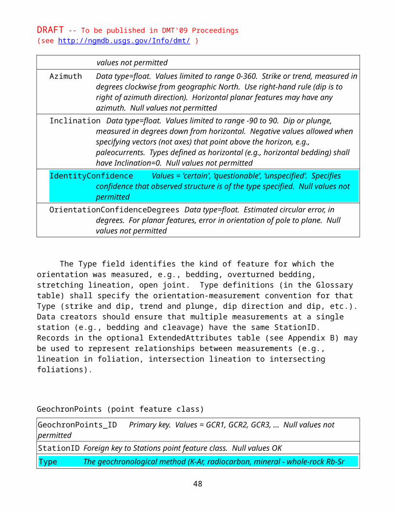
DRAFT -- To be published in DMT'09 Proceedings(see http://ngmdb.usgs.gov/Info/dmt/ )
Clastic sediment -- A sediment formed by the weathering and erosion of preexisting rocks or minerals; the eroded particles or "clasts" are transported and deposited by grav-ity, air, water, or ice.
Sand and gravel of unspecified origin -- A sediment composed mostly of sand and (or) gravel, formed by the weathering and erosion of preexisting rocks or minerals; the eroded particles or "clasts" are transported and deposited by grav-ity, air, water, or ice.
Silt and clay of unspecified origin -- A sediment composed mostly of silt and (or) clay, formed by the weathering and erosion of preexisting rocks or miner-als; the eroded particles or "clasts" are transported and deposited by gravity, air, water, or ice.
Alluvial sediment -- Unconsolidated material deposited by a stream or other body of running water, as a sorted or semi-sorted sediment in the bed of the stream or on its floodplain or delta, or as a cone or fan at the base of a mountain slope. Grain size varies from clay to gravel.
o Alluvial sediment, mostly coarse-grained -- Unconsolidated material deposited by a stream or other body of running water, as a sorted or semi-sorted sediment in the bed of the stream or on its floodplain or delta, or as a cone or fan at the base of a mountain slope. This sediment is mostly sand and gravel, but may contain some mud and (or) cobbles and boulders.
o Alluvial sediment, mostly fine-grained -- Unconsolidated material de-posited by a stream or other body of running water, as a sorted or semi-sorted sediment in the bed of the stream or on its floodplain or delta, or as a cone or fan at the base of a mountain slope. This sediment is mostly silt and clay, but may contain some coarser material (e.g., sand, gravel).
Glacial till -- Mostly unsorted and unstratified material, generally unconsoli-dated, deposited directly by and underneath a glacier without subsequent re-working by meltwater, and consisting of a heterogeneous mixture of clay, silt, sand, gravel, and boulders ranging widely in size and shape.
o Glacial till, mostly sandy -- Mostly unsorted and unstratified material, generally unconsolidated, deposited directly by and underneath a glacier without subsequent reworking by meltwater, and consisting of clay, silt, sand, gravel, and boulders ranging widely in size and shape. Relatively sandy in texture.
o Glacial till, mostly silty -- Mostly unsorted and unstratified material, generally unconsolidated, deposited directly by and underneath a glacier without subsequent reworking by meltwater, and consisting of a heterogeneous mixture of clay, silt, sand, gravel, and boulders ranging widely in size and shape. Relatively loamy (silty) in texture.
o Glacial till, mostly clayey -- Mostly unsorted and unstratified material, generally unconsolidated, deposited directly by and underneath a glacier without subsequent reworking by meltwater, and consisting of a heterogeneous mixture of clay, silt, sand, gravel, and boulders ranging widely in size and shape. Relatively clayey in texture.
Ice-contact and ice-marginal sediment -- Mostly sand, silt, and gravel-sized particles or "clasts" derived from rock or preexisting sediment eroded and trans-ported by glaciers. As the ice melted, this material was deposited by running water essentially in contact with glacial ice, or was transported and deposited by
48

DRAFT -- To be published in DMT'09 Proceedings(see http://ngmdb.usgs.gov/Info/dmt/ )
glacially fed streams. Includes sediment deposited into water bodies adjacent to the glacial ice margin.
o Ice-contact and ice-marginal sediment, mostly coarse-grained -- Mostly sand and gravel-sized particles or "clasts," with lesser silt and clay, derived from rock or preexisting sediment eroded and transported by glaciers. As the ice melted, this material was deposited by running water essentially in contact with glacial ice, or was transported and de-posited by glacially fed streams. Includes sediment deposited into wa-ter bodies adjacent to the glacial ice margin.
o Ice-contact and ice-marginal sediment, mostly fine-grained -- Mostly silt and clay-sized particles or "clasts," with lesser sand and gravel, derived from rock or preexisting sediment eroded and trans-ported by glaciers. As the ice melted, this material was deposited by running water essentially in contact with glacial ice, or was transported and deposited by glacially fed streams. Includes sediment deposited into water bodies adjacent to the glacial ice margin.
Eolian sediment -- Silt- and sand-sized sediment deposited by wind.o Dune sand -- Mostly sand-sized sediment deposited by wind. Typi-
cally characterized by various dune landforms.o Loess -- Silty material deposited by winds near the glacial margin.
Lacustrine sediment -- Mostly well sorted and well bedded material ranging in grain size from clay to gravel, deposited in perennial to intermittent lakes. Much of the sediment is derived from material eroded and transported by streams. Includes deposits of lake-marginal beaches and deltas.
o Lacustrine sediment, mostly coarse-grained -- Mostly well-sorted and well-bedded material, generally sand- and gravel-sized with lesser silt and clay, deposited in perennial to intermittent lakes. Much of the sediment is derived from material eroded and transported by streams. Includes deposits of lake-marginal beaches and deltas.
o Lacustrine sediment, mostly fine-grained -- Mostly well-sorted and well-bedded material, generally silt- and clay-sized with lesser sand and gravel, deposited in perennial to intermittent lakes. Much of the sedi-ment is derived from material eroded and transported by streams. In-cludes deposits of lake-marginal beaches and deltas.
Playa sediment -- Fine-grained sediment and evaporite salts deposited in ephemeral lakes in the centers of undrained basins. Includes material deposited in playas, mudflats, salt flats, and adjacent saline marshes. Generally interbed-ded with eolian sand and with lacustrine sediment deposited during wetter cli-matic periods; commonly intertongue upslope with sediment deposited by allu-vial fans.
Coastal zone sediment -- Mud and sandy sediment deposited in beach, barrier island, nearshore marine deltaic, or in various low-energy shoreline (mud flat, tidal flat, sabka, algal flat) settings.
o Coastal zone sediment, mostly coarser grained -- Mostly sand-, silt-, and gravel-sized sediment deposited on beaches and dunes, and in shal-low marine and related alluvial environments.
o Coastal zone sediment, mostly fine-grained -- Mostly clay- and silt-sized sediment deposited in lagoons, tidal flats, backbarriers, and coastal marshes.
49

DRAFT -- To be published in DMT'09 Proceedings(see http://ngmdb.usgs.gov/Info/dmt/ )
Marine sediment -- Mud and sandy sediment deposited in various marine set-tings. Sediment may originate from erosion of rocks and sediments on land, or from marine organisms (of carbonate or siliceous composition).
o Marine sediment, mostly coarser grained -- Mud and sandy sediment derived from erosion or rocks and sediment on land, transport by streams, and deposition on marine deltas and plains. Sediment there-fore is mostly siliceous in composition.
o Marine sediment, mostly fine-grained – Mostly clay- and silt-sized sediment deposited in relatively deep, quiet water, far removed from ar-eas where coarser grained clastic sediments are washed into the marine environment. Includes sediment derived from marine organisms.
Mass movement sediment -- Formed by downslope transport of particles or "clasts" produced by weathering and breakdown of the underlying rock, sedi-ment, and (or) soil. Composed of poorly sorted and poorly stratified material ranging in size from clay to boulders. Includes colluvium, landslides, talus, and rock avalanches.
o Colluvium and other widespread mass-movement sediment -- Formed by relatively widespread and slow downslope transport of parti-cles or "clasts" produced by weathering and breakdown of the underly-ing rock, sediment, and (or) soil. Composed of poorly sorted and poorly stratified material ranging in size from clay to boulders.
o Debris flows, landslides, and other localized mass-movement sedi-ment -- Formed by relatively localized downslope transport of particles or "clasts" produced by weathering and breakdown of the underlying rock, sediment, and (or) soil. Composed of poorly sorted and poorly stratified material ranging in size from clay to boulders. Commonly, the slopes on which this material occurs fail because of water, earth-quake, or volcanic activity, and this material is then transported and de-posited downslope. The speed of sediment transport ranges from rapid to imperceptible.
Residual material -- Unconsolidated material presumed to have developed in place, by weathering of the underlying rock or sediment. Usually forms a relatively thin surface layer that conceals the unweathered or partly altered source material below, and is the material from which soils are formed.
Carbonate sediment -- A sediment formed by the biotic or abiotic precipitation from aqueous solution of carbonates of calcium, magnesium, or iron; e.g., limestone and dolomite.
Peat and muck -- An unconsolidated material principally composed of plant remains, with lesser amounts of generally fine-grained clastic sediment. Deposited in a water-saturated environment such as a swamp, marsh, or bog. It is an early stage or rank in the development of coal.
o Sedimentary rock -- Consolidated material (rock) composed of particles deposited by gravity, air, water, or ice, or as accumulated by other natural agents operating at Earth's surface such as chemical precipitation or secretion by organisms. Does not here include sedimentary material directly deposited as a result of volcanic activity.
Clastic sedimentary rock -- Sedimentary rock that is composed dominantly of particles or "clasts" derived by erosion, weathering, or mass-wasting of preexisting rock, and de-posited by gravity, air, water, or ice.
Conglomerate -- Sedimentary rock that is composed dominantly of particles or "clasts" derived by erosion and weathering of preexisting rock, and containing more than 30 percent gravel-sized particles.
50

DRAFT -- To be published in DMT'09 Proceedings(see http://ngmdb.usgs.gov/Info/dmt/ )
Sandstone -- Sedimentary rock that is composed dominantly of particles or "clasts" derived by erosion and weathering of preexisting rock, consisting mostly of sand-sized particles, with or without a fine-grained matrix of silt or clay.
Mostly sandstone -- This area is underlain by sequences of various sedimentary rocks that, for this generalized map depiction, are too complex to be shown sep-arately. Mostly sandstone, interbedded with other sedimentary rocks which lo-cally may include conglomerate and finer grained clastics (mudrock), carbon-ates, and (or) coal.
Sandstone and mudstone -- Approximately equal (or unspecified) proportion of sandstone and mudstone (which includes shale and siltstone).
Mudstone -- Sedimentary rock that is composed dominantly of particles or "clasts" derived by erosion and weathering of preexisting rock, consisting mostly of mud (silt- and clay-sized particles). Includes shale and siltstone.
Mostly mudstone -- This area is underlain by sequences of various sedimentary rocks that, for this generalized map depiction, are too complex to be shown sep-arately. Mostly mudstone, interbedded with other sedimentary rocks which lo-cally may include coarser grained clastics (sandstone, conglomerate), carbon-ates, and (or) coal.
Carbonate rock -- A sedimentary rock such as limestone or dolomite, consisting chiefly of carbonate minerals.
Mostly carbonate rock -- This area is underlain by sequences of various sedimentary rocks that, for this generalized map depiction, are too complex to be shown separately. Mostly carbonate rock, interbedded with clastic sedimentary rock.
Evaporitic rock -- Sedimentary rock composed primarily of minerals produced by evaporation of a saline solution. Examples include gypsum, anhydrite, other diverse sulfates, halite (rock salt), primary dolomite, and various nitrates and borates.
Iron-rich sedimentary rock -- Sedimentary rock in which at least 50 percent of the ob-served minerals are iron-bearing (hematite, magnetite, limonite-group, siderite, iron sul-fides).
Coal and lignite -- Organic rich sedimentary rock formed from the compaction and al-teration of plant remains. Coal is a consolidated, hard black organic rock, whereas lig-nite is a semiconsolidated brown to black, earthy material, which may contain large par-ticles of recognizable plant parts and tends to crack upon drying.
Sedimentary and extrusive igneous material -- This area is underlain either by (1) sedimentary rock and (or) unconsolidated material (sediment) and by extrusive igneous material (volcanic rock and (or) sediment) or (2) by volcanic rock and (or) sediment and by such material after erosion and redeposition.
Igneous rock -- Rock that solidified from molten or partly molten material (i.e., magma). o Extrusive igneous material -- Molten material that was erupted onto the surface of the Earth,
fusing into rock or remaining as unconsolidated particles. Includes lava flows and pyroclastic material such as volcanic ash.
Volcaniclastic (fragmental) material -- Rock and unconsolidated material consisting of particles or "clasts" that were formed by volcanic explosion or aerial expulsion from a volcanic vent.
Pyroclastic flows -- Hot ash, pumice, and rock fragments erupted from a vol-cano. This material moves downslope commonly in chaotic flows. Once de-posited, the material may deform and weld together because of the intense heat and the weight of the overlying material.
o Felsic-composition pyroclastic flows -- Hot ash, pumice, and rock fragments erupted from a volcano. This material moves downslope commonly in chaotic flows. Once deposited, the material may deform
51

DRAFT -- To be published in DMT'09 Proceedings(see http://ngmdb.usgs.gov/Info/dmt/ )
and weld together because of the intense heat and the weight of the overlying material. Composed of light-colored rocks (e.g., rhyolite, dacite, trachyte, latite) which, because of their high-silica content and resulting high viscosity, tend to erupt explosively.
o Intermediate-composition pyroclastic flows -- Hot ash, pumice, and rock fragments erupted from a volcano. This material moves downs-lope commonly in chaotic flows. Once deposited, the material may de-form and weld together because of the intense heat and the weight of the overlying material. Composed of rocks (e.g., andesite) intermediate in color and mineral composition between felsic and mafic rocks. An-desite magma commonly erupts from stratovolcanoes as thick lava flows but also can generate strong explosive eruptions to form pyroclas-tic flows.
o Mafic-composition pyroclastic flows -- Hot ash, pumice, and rock fragments erupted from a volcano. This material moves downslope commonly in chaotic flows. Once deposited, the material may deform and weld together because of the intense heat and the weight of the overlying material. Composed of dark-colored rocks (e.g., basalt) which, because of their low-silica content and resulting low viscosity, tend to erupt gently as lava flows rather than more forcefully as pyro-clastic flows.
Air-fall tephra -- Fragments of volcanic rock and lava, of various sizes, are known as "tephra." This material is carried into the air by explosions and by hot gases in eruption columns or lava fountains. As tephra falls to the ground with increasing distance from a volcano, the average size of the individual rock parti-cles and the thickness of the resulting deposit decrease. At some distance from a volcano, the deposit is known as volcanic ash.
o Felsic-composition air-fall tephra -- Fragments of volcanic rock and lava, of various sizes, are known as "tephra." This material is carried into the air by explosions and by hot gases in eruption columns or lava fountains. As tephra falls to the ground with increasing distance from a volcano, the average size of the individual rock particles and the thick-ness of the resulting deposit decrease. Composed of light-colored rocks (e.g., rhyolite, dacite, trachyte, latite) which, because of their high-silica content and resulting high viscosity, tend to erupt explosively, readily forming pumice and volcanic ash.
o Intermediate-composition air-fall tephra -- Fragments of volcanic rock and lava, of various sizes, are known as "tephra." This material is carried into the air by explosions and by hot gases in eruption columns or lava fountains. As tephra falls to the ground with increasing distance from a volcano, the average size of the individual rock particles and the thickness of the resulting deposit decrease. Composed of rocks (e.g., andesite) intermediate in color and mineral composition between felsic and mafic rocks. Andesite magma commonly erupts from stratovolca-noes as thick lava flows but also can generate strong explosive erup-tions, readily forming pumice and volcanic ash.
o Mafic-composition air-fall tephra -- Fragments of volcanic rock and lava, of various sizes, are known as "tephra." This material is carried into the air by explosions and by hot gases in eruption columns or lava fountains. As tephra falls to the ground with increasing distance from a volcano, the average size of the individual rock particles and the thick-
52

DRAFT -- To be published in DMT'09 Proceedings(see http://ngmdb.usgs.gov/Info/dmt/ )
ness of the resulting deposit decrease. Composed of dark-colored rocks (e.g., basalt) which, because of their low-silica content and resulting low viscosity, tend to erupt gently as lava flows rather than more force-fully, and so these deposits are uncommon.
Lava flows -- A lateral, surficial outpouring of molten lava from a vent or a fissure, and the solidified body of rock that forms when it cools. Composed generally of fine-grained, dark-colored rocks (e.g., basalt), and tends to form extensive sheets with gener-ally low relief except in the vent areas where cinder cones or shield volcanoes may form. Includes basaltic shield volcanoes, which may become very large (e.g., Hawaii).
Felsic-composition lava flows -- A lateral, surficial outpouring of molten lava from a vent or a fissure, and the solidified body of rock that forms when it cools. Composed of fine-grained, light-colored rocks which, because of their high-silica content and resulting high viscosity, tend to erupt explosively, and so these deposits are uncommon. Includes rhyolitic, dacitic, trachytic, and latitic rock.
Intermediate-composition lava flows -- A lateral, surficial outpouring of molten lava from a vent or a fissure, and the solidified body of rock that forms when it cools. Composed of fine-grained rocks intermediate in color and min-eral composition between felsic and mafic rocks, and commonly erupts from stratovolcanoes as thick lava flows. Includes andesitic rock.
Mafic-composition lava flows -- A lateral, surficial outpouring of molten lava from a vent or a fissure, and the solidified body of rock that forms when it cools. Composed of fine-grained, dark-colored rocks, and tends to form exten-sive sheets with generally low relief. Includes basaltic shield volcanoes, which may become very large (e.g., Hawaii). Includes basaltic rock.
o Intrusive igneous rock -- Rock that solidified from molten or partly molten material (i.e., magma), forming below the Earth's surface.
Coarse-grained intrusive igneous rock -- Rock that solidified from molten or partly molten material (i.e., magma). It formed at some depth beneath the Earth's surface, thereby cooling slowly enough for mineral crystals to grow to a size large enough to be visible to the naked eye.
Coarse-grained, felsic-composition intrusive igneous rock -- Rock that solid-ified from molten or partly molten material (i.e., magma). It formed at some depth beneath the Earth's surface, thereby cooling slowly enough for mineral crystals to grow to a size large enough to be visible to the naked eye. Com-posed mostly of light-colored minerals. Includes granitic, syenitic, and mon-zonitic rock.
Coarse-grained, intermediate-composition intrusive igneous rock -- Rock that solidified from molten or partly molten material (i.e., magma). It formed at some depth beneath the Earth's surface, thereby cooling slowly enough for min-eral crystals to grow to a size large enough to be visible to the naked eye. Inter-mediate in color and mineral composition between felsic and mafic igneous rock. Includes dioritic rock.
Coarse-grained, mafic-composition intrusive igneous rock -- Rock that so-lidified from molten or partly molten material (i.e., magma). It formed at some depth beneath the Earth's surface, thereby cooling slowly enough for mineral crystals to grow to a size large enough to be visible to the naked eye. Com-posed mostly of dark-colored minerals. Includes gabbroic rock.
Ultramafic intrusive igneous rock -- Rock that solidified from molten or partly molten material (i.e., magma). It formed at some depth beneath the Earth's surface, thereby cooling slowly enough for mineral crystals to grow to a
53

DRAFT -- To be published in DMT'09 Proceedings(see http://ngmdb.usgs.gov/Info/dmt/ )
size large enough to be visible to the naked eye. Composed mostly of mafic minerals, e.g., monomineralic rocks composed of hypersthene, augite, or olivine.
Fine-grained intrusive igneous rock -- Rock that solidified from molten or partly molten material (i.e., magma). It formed at shallow depths beneath the Earth's surface, thereby cooling quickly. These rocks generally are fine-grained, but may contain large mineral crystals (phenocrysts), and they occur as tabular dikes or sills.
Fine-grained, felsic-composition intrusive igneous rock -- Rock that solidi-fied from molten or partly molten material (i.e., magma). It formed at shallow depths beneath the Earth's surface, thereby cooling quickly. These rocks gener-ally are fine-grained, but may contain large mineral crystals (phenocrysts), and they occur as tabular dikes or sills. Composed mostly of light-colored minerals. Includes rhyolitic, dacitic, trachytic, and latitic rock.
Fine-grained, intermediate-composition intrusive igneous rock -- Rock that solidified from molten or partly molten material (i.e., magma). It formed at shallow depths beneath the Earth's surface, thereby cooling quickly. These rocks generally are fine-grained, but may contain large mineral crystals (phe-nocrysts), and they occur as tabular dikes or sills. Intermediate in color and mineral composition between felsic and mafic igneous rock. Includes andesitic rock.
Fine-grained, mafic-composition intrusive igneous rock -- Rock that solidi-fied from molten or partly molten material (i.e., magma). It formed at shallow depths beneath the Earth's surface, thereby cooling quickly. These rocks gener-ally are fine-grained, but may contain large mineral crystals (phenocrysts), and they occur as tabular dikes or sills. Composed mostly of dark-colored minerals. Includes basaltic rock.
Exotic-composition intrusive igneous rock -- Rock that solidified from molten or partly molten material (i.e., magma), forming below the Earth's surface and having ex-otic mineralogical, textural, or field setting characteristics. These rocks typically are dark colored with abundant phenocrysts. Includes kimberlite, lamprophyre, lamproite, and foiditic rocks.
Igneous and metamorphic rock -- Consists of coarse-grained intrusive igneous rocks and generally medium to high grade metamorphic rocks.
Metamorphic rock -- A rock derived from preexisting rocks by mineralogical, chemical, or structural changes, essentially in the solid state, in response to marked changes in temperature, pressure, shearing stress, and chemical environment, generally at depth in the Earth's crust.
o Regional metamorphic rock, of unspecified origin -- A rock derived from preexisting rocks by mineralogical, chemical, or structural changes, essentially in the solid state, in response to marked regional changes in temperature, pressure, shearing stress, and chemical environment, generally at depth in the Earth's crust. In this area, the origin of the preexisting rock is mixed (e.g., igneous and sedimentary) or is not known.
Medium and high-grade regional metamorphic rock, of unspecified origin -- A rock derived from preexisting rocks by mineralogical, chemical, or structural changes, essen-tially in the solid state, in response to relatively intense regional changes in temperature, pressure, shearing stress, and chemical environment, generally at depth in the Earth's crust. In this area, the origin of the preexisting rock is mixed (e.g., igneous and sedi-mentary) or is not known. Includes rocks such as amphibolite, granulite, schist, and gneiss.
Contact-metamorphic rock -- Rock that originated by local processes of thermal meta-morphism, genetically related to the intrusion and extrusion of magmas and taking place in rocks at or near their contact with a body of igneous rock. Metamorphic changes are
54

DRAFT -- To be published in DMT'09 Proceedings(see http://ngmdb.usgs.gov/Info/dmt/ )
effected by the heat and fluids emanating from the magma and by some deformation be-cause of emplacement of the igneous mass.
Deformation-related metamorphic rock -- A rock derived from preexisting rocks by mineralogical, chemical, or structural changes, essentially in the solid state, in response to marked changes in temperature, pressure, shearing stress, and chemical environment. Generally forms in narrow, planar zones of local deformation (e.g., along faults) and characterized by foliation or alignment of mineral grains. Includes mylonite.
o Metasedimentary rock -- A rock derived from preexisting sedimentary rocks by mineralogical, chemical, or structural changes, essentially in the solid state, in response to marked changes in temperature, pressure, shearing stress, and chemical environment, generally at depth in the Earth's crust.
Slate and phyllite, of sedimentary rock origin -- A fine-grained rock derived from preexisting sedimentary rocks by mineralogical, chemical, or structural changes, essen-tially in the solid state, in response to marked changes in temperature, pressure, shearing stress, and chemical environment, generally at depth in the Earth's crust. Includes phyl-lite and slate, which is a compact, fine-grained rock that possesses strong cleavage and hence can be split into slabs and thin plates. Mostly formed from fine-grained material such as mudstone.
Schist and gneiss, of sedimentary rock origin -- A foliated rock derived from preexist-ing sedimentary rocks by mineralogical, chemical, or structural changes, essentially in the solid state, in response to marked changes in temperature, pressure, shearing stress, and chemical environment, generally at depth in the Earth's crust. Includes schist (char-acterized by such strong foliation or alignment of minerals that it readily splits into flakes or slabs) and gneiss (characterized by alternating, irregular bands of different mineral composition). Mostly formed from fine-grained material such as mudstone.
Marble -- A rock derived from preexisting (commonly carbonate) sedimentary rocks by mineralogical, chemical, or structural changes, essentially in the solid state, in response to marked changes in temperature, pressure, shearing stress, and chemical environment, generally at depth in the Earth's crust. Characterized by recrystallization of the carbon-ate minerals in the source rock.
Quartzite -- A rock derived from preexisting (commonly sandstone) sedimentary rocks by mineralogical, chemical, or structural changes, essentially in the solid state, in re-sponse to marked changes in temperature, pressure, shearing stress, and chemical envi-ronment, generally at depth in the Earth's crust. Characterized by recrystallization of quartz in the source rock.
o Metaigneous rock -- A rock derived from preexisting igneous rocks (mostly extrusive in origin) by mineralogical, chemical, or structural changes, essentially in the solid state, in response to marked changes in temperature, pressure, shearing stress, and chemical environment, generally at depth in the Earth's crust. Mafic and ultramafic schists and gneisses are common.
Other materials:o Rock and sediment -- Various rocks and sediment, not differentiated.o Rock -- Various rock types, not differentiated.o "Made" or human-engineered land -- Modern, unconsolidated material known to have hu-
man-related origin.o Water or iceo Unmapped area
These definitions were adapted from a variety of published and unpublished works, including:
55

DRAFT -- To be published in DMT'09 Proceedings(see http://ngmdb.usgs.gov/Info/dmt/ )
Blatt, Harvey, Tracy, R.J., and Owens, B.E., 2006, Petrology – Igneous, sedimentary, and metamorphic, 3rd ed.: W.H. Freeman and Company, New York, 530 p.
Hyndman, D.W., 1985, Petrology of igneous and metamorphic rocks, 2nd ed.: McGraw-Hill, Inc., New York, 576 p.
Neuendorf, K.K.E., Mehl, J.P., Jr., and Jackson, J.A., 2005, Glossary of geology, 5th ed.: American Ge-ological Institute, Alexandria, VA., 779 p.
North American Geologic Map Data Model Steering Committee Science Language Technical Team, 2004, Report on Progress to Develop a North American Science-Language Standard for Digital Geologic-Map Databases, in Soller, D.R., ed., Digital Mapping Techniques '04 -- Workshop Proceedings: U.S. Geological Survey Open-File Report 2004-1451, p. 85-94 and 4 appendices containing the science terminologies, http://pubs.usgs.gov/of/2004/1451/nadm/.
National Geologic Map Database Project, 2007, Science vocabulary to support the National Geologic Map Database project: Lithology terms: U.S. Geological Survey unpublished document, 218 p.
Soller, D.R., and Reheis, M.C., compilers, 2004, Surficial materials in the conterminous United States: U.S. Geological Survey Open-File Report 03-275, scale 1:5,000,000, http://pubs.usgs.gov/of/2003/of03-275/.
USGS Photo glossary of volcanic terms, 2008, USGS Volcano Hazards Program Web site, http://volca-noes.usgs.gov/images/pglossary/index.php.
GeneralLithologyConfidence
Term Definition
High The term and definition adequately characterize the overall lithologic nature of rocks and sediments in the map unit. Regarding the subjective term “adequately characterize”, we refer to context and objectives of this classification as described in the documentation.
Medium The term and definition generally characterize the overall lithology of the map unit, but there are one or more significant minor lithologies that are not adequately described by the selected term.
Low The overall lithology of this map unit is not adequately classifiable using this list of terms and definitions, but the term selected is the best available. Or this map unit is insufficiently known to confidently assign a GeneralLithology term.
NOTE: Please refer to the introductory note of this appendix, particularly the scope and intent, before assigning confidence values. We intend to use the confidence information to evaluate and revise GeneralLithology.
56

DRAFT -- To be published in DMT'09 Proceedings(see http://ngmdb.usgs.gov/Info/dmt/ )
APPENDIX B. OPTIONAL ELEMENTSSome parts of a geologic map publication may, if present, be encoded as image files
(e.g., .pdf, .ps, .tiff) or may, at the option of the publisher, be encoded within the geodatabase. We also define several non-spatial tables (ExtendedAttributes, GeologicEvents, and StandardLithology) that some map publishers may find useful. These are optional elements.
We expect that with further experience it may eventually be desirable to require that cross sec-tions and Correlation of Map Units diagrams be encoded in the geodatabase.
Cross Sections (feature datasets)
Cross sections should be identified as cross-section A, cross-section B, cross-section C, and so on, abbreviated as CSA, CSB, CSC in the dataset and feature class names. Each cross section exists in a separate map-space, and thus requires a separate feature dataset for each cross section. For each cross section there are, at a minimum, two feature classes:
CSAContactsAndFaults (primary key is CSAContactsAndFaults_ID, values = CSACOF1, CSACOF2, … )
CSAMapUnitPolys (primary key is CSAMapUnitPolys_ID, values = CSAMUP1, CSAMUP2, … )
Field names, data types, usage, and topology rules for these feature classes are identical with those for ContactsAndFaults and MapUnitPolys. If lines that don't participate in MapUnit topology or point-based data are depicted on the cross-section, the appropriate feature classes (e.g., CSAGeologi-cLines, CSAOrientationPoints) should be created.
Correlation of Map Units (feature dataset)The Correlation of Map Units (CMU) diagram found on many geologic maps can be encoded as
a feature dataset in a geodatabase. Doing so makes it easier to match symbolization of the CMU to that of the map and stores the information in the CMU in a fashion that is (slightly) more queryable than storing the CMU as a simple image. Two feature classes are necessary and a third (CMUText) will al-most always be needed. If map units are depicted as point features an additional feature class is needed.
Note that inclusion of a CorrelationOfMapUnits diagram in a map report is NOT optional. En-coding the CMU as GIS features is optional.
CMUMapUnitPolys (polygon feature class)
Fields:
57

DRAFT -- To be published in DMT'09 Proceedings(see http://ngmdb.usgs.gov/Info/dmt/ )
CMUMapUnitPolys_ID Primary key. Example values = CMUMUP1, CMUMUP2, CMUMUP3, … Null values not permitted
MapUnit Foreign key to DescriptionOfMapUnits. Null values not permittedLabel Value = MapUnit//Label. Null values OKSymbol References a symbol in accompanying style file. Null values OKRuleID Data type = integer. If Cartographic Representations are used, this field is re-
quired; otherwise it is not included in the table (see Symbolization section)Override Data type = blob. If Cartographic Representations are used, this field is required;
otherwise it is not included in the table (see Symbolization section)
Values for Symbol and Label are calculated with reference to DescriptionOfMapUnits. Ghost boxes (e.g., protolith of a metamorphic unit) may be shown as MapUnitPolys with Symbol = ‘blank’. Or the box outline alone can be stored in CMULines.
CMULines (line feature class)
Fields:
CMULines_ID Values are CMULIN1, CMULIN2, CMULIN3, … Null values not permittedType Term to classify meaning of lines. Example values = ‘contact’, ‘ghost contact’,
‘CMU leader’, ‘CMU rule’, ‘CMU bracket’, or ‘<MapUnit> line’. Values must be defined in Glossary. Null values not permitted
Symbol References a symbol in accompanying style file. Null values OKRuleID Data type = integer. If Cartographic Representations are used, this field is re-
quired; otherwise it is not included in the table (see Symbolization section)Override Data type = blob. If Cartographic Representations are used, this field is required;
otherwise it is not included in the table (see Symbolization section)
CMUText (annotation feature class)
Fields:
CMUText_ID Primary key. Example values = CMUTEX1, CMUTEX2, CMUTEX3, … Null val-ues not permitted
ParagraphStyle Null values not permittedText Text to displayAdditional fields as implemented by GIS software
Annotation text and annotation attributes, including font, font size, font effects, and text angle, are stored in default fields of the annotation feature class. Values for font, font size, and font effects can be calculated from ParagraphStyle.
58

DRAFT -- To be published in DMT'09 Proceedings(see http://ngmdb.usgs.gov/Info/dmt/ )
CMUPoints (point feature class)
Fields:
CMUPoints_ID Primary key. Example values = CMUPNT1, CMUPNT2, CMUPNT3, … Null val-ues not permitted
Type Values are ‘<MapUnit> point’. Values must be defined in Glossary. Null values not permitted
Symbol Null values OKLabel Text string to display in association with symbol at this pointRuleID Data type = integer. If Cartographic Representations are used, this field is re-
quired; otherwise it is not included in the table (see Symbolization section)Override Data type = blob. If Cartographic Representations are used, this field is required;
otherwise it is not included in the table (see Symbolization section)
ExtendedAttributes (non-spatial table)
The ExtendedAttributes table provides a general structure for linking attributes of any sort with any data item (identified table row) in the database.
Fields:
ExtendedAttributes_ID Primary key. Example values = EXA1, EXA2, EXA3, … Null values not permitted
OwnerTable Full name of table that contains owning element, e.g., DescriptionOfMapUnits, or OverlayPolys. May be any table in the database. Null values not permitted
OwnerID Foreign key to table specified by the OwnerTable value. If Owner_ID record is deleted, associated extended attribute should be deleted (cascade delete). Conven-tion is that this Foreign key will link to the TableName_ID field in the OwnerTable. Null values not permitted
Property Name of property specified by this attribute or relationship between Owner and Val-ueLinkID items. Values defined in Glossary or external glossary; we strongly rec-ommend Glossary definitions of all properties used in the ExtendedAttributes table. Definition of property should include explanation of formatting and units used to specify property values. Null values not permitted
PropertyValue String, could be number (+ measurement unit) or defined term. Not closed. Data-entry tool might enforce consistency between PropertyValue and Property (such that Property=thickness does not have PropertyValue=fine-grained). NG-MDB or individual projects might choose to supply Property | PropertyValues lists. Numeric values (for instance, 546.81 yards) are not defined in Glossary. If null, ValueLinkID must be non-null
ValueLinkID Foreign key to data instance that specifies property value. For example, GrainSize-Analyses_3. Or a link to another ExtendedAttributes record (e.g., this thing overlies / succeeds / is-a-part-of another thing). Null values OK. If null, PropertyValue
59

DRAFT -- To be published in DMT'09 Proceedings(see http://ngmdb.usgs.gov/Info/dmt/ )
must be non-null, and vice-versa. Definition of Property must specify table to which the ValueLinkID is a foreign foreign key. If null, PropertyValue must be non-null
Qualifier Expresses variability or extent of PropertyValue. Must be defined in Glossary or an external glossary. Null values OK
Notes Free text. Null values OKDataSourceID Foreign key to DataSources table, to track provenance of each data element. Null
values not permitted
Some example ExtendedAttributes records:
Extended-Attribute_ID
OwnerTable Owner-ID
Property Property-Value
Value-LinkID
Qualifier Notes Data-SourceID
EA01650 Description-OfMapUnits
DMU3 Permeability Low Typical Rock is full of alteration clays
DS2140
EA01654 Description-OfMapUnits
DMU3 Permeability High Rare DS0001
EA01680 Description-OfMapUnits
DMU27 Metamorphic Grade
Low Uncommon DS0364
EA0162476 Description-OfMapUnits
DMU27 Metamorphic Grade
Medium Typical DS2069
EA01636 Description-OfMapUnits
DMU27 Metamorphic Age
Early Pro-terozoic
Probable DS2106
EA01639 Description-OfMapUnits
DMU27 Metamorphic Age
Middle Cre-taceous
Possible DS045
EA016289 Geologic-Events
Slip-Event1
Displacement 4 km DS1045
EA016233 Geologic-Events
Slip-Event1
Displace-mentType
Right-lateral strike slip
DS1130
EA016123 Geologic-Events
Slip-Event1
Successor GE2466 DS1205
EA0160978 Geologic-Events
GE2466 Displacement 200 km DS1135
EA0167032 Geologic-Events
GE2466 Displace-mentType
Right-lateral strike slip
DS0980
EA016086 Description-OfMapUnits
Txt Permeability Low Rock is full of alteration clays
DS8625
EA016146 MapUnit-Polys
Txt37a Note Big out-crop, good place for a quarry
DS2586
EA016826 Contacts-AndFaults
COF22 Has Photo-graph
Photo2008-11-12b
DS2640
EA016926 Contacts-AndFaults
COF22 Contact Char-acter
Gradational DS3656
ExtendedAttributes uses a pattern that associates a data item identified by ‘OwnerTable/OwnerID’ with a property-value pair. The property is identified by the value in the ‘Property’ field, and the property value is specified by the ‘PropertyValue’ or ‘ValueLinkID’. PropertyValue is used when the value can be represented by a single string or number. For property values that are themselves data-base rows, the ValueLinkID is the identifier for the database row that contains the value. Because there is no separate PropertyValueTable field, the identifier in ValueLinkID must convey the table that con-
60

DRAFT -- To be published in DMT'09 Proceedings(see http://ngmdb.usgs.gov/Info/dmt/ )
tains the linked data using the convention that the first part of the identifier is a table identifier. In addi-tion, each attribute assignment may have a qualifier, may have notes related to the attribute value, and has an identified data source. The Qualifier is an optional attribute used to express quality, frequency, or intensity; vocabulary used in this field must be explained by corresponding Glossary table entries.
Data engineers will recognize this as the fundamental subject-predicate-object pattern, analo-gous to an RDF triple, with the addition of metadata for each statement. This data structure could be used to express everything in the database, but its use requires creation of database views. It is in-cluded here to provide a mechanism to add content that may be sparse (available for only a few of many possible items), or attributes that may have multiple values (many to many relationships). For data that cannot be represented using the other NCGMP09 database tables, the map author must decide whether these data are essential and if so, whether these data should be stored in ExtendedAttributes or in a new datatype-specific table. We anticipate that best-practice recommendations will emerge for particular kinds of data.
If normalized data are to be recoverable from the ExtendedAttributes data structure, each of the extended attributes instances must represent a single fact. For example, to represent a slip displace-ment event in a sequence of displacements on a complex fault or fault segment: “San Andreas Slip Event 1, Displacement 4 km right lateral strike slip” is composed of several facts: 1. SanAndreasFault has GeologicEvent xxxx; 2. GeologicEvent xxxx has SuccessorEvent = GeologicEvent yyyy (if there is a slipEvent2); 3. GeologicEvent xxxx has displacementMagnitude_m = 4000; 4. GeologicEvent xxxx has displacementType = ‘Right Lateral Strike Slip’. The GeologicEvent xxxx age value is the time bracket for the slip event. ‘San Andreas fault’ might be a concept in the Glossary that is associated with many individual fault segments in ContactsAndFaults feature class through other ExtendedAt-tributes links. Each of these facts would be a separate row in the ExtendedAttributes table.
The OwnerID in ExtendedAttributes is a foreign key that links to a data instance in any table, e.g., DescriptionOfMapUnits, Glossary (for named faults that are ‘supersets’ of elements in the Con-tactsAndFaults feature class), MapUnitPolys for description of individual polygons, or GeologicEvents to describe a displacement event (if logic above is followed) or to add additional process and environ-mental information associated with an event. Map units should be referenced by DescriptionOfMa-pUnits_ID, not MapUnit. This contrasts with use of MapUnit as foreign key to the DescriptionOfMa-pUnits table in other parts of the geodatabase; the alternate convention is adopted here for consistency with references from ExtendedAttributes to other database tables. The ‘OwnerTable’ attribute is the name of the table that OwnerID references. We expect that explicit identification of OwnerTable will speed searches that otherwise would have to reference the entire world of _ID values within the geo-database. The same performance issue is raised by the ValueLinkID property, but in this case the Glos-sary definition of the ExtendedAttribute property should specify the table that contains the linked val-ues.
ValueLinkID allows links to data elements in other tables as values for attributes. Having a pointer value to specify a property opens the door for use of ExtendedAttributes to represent many kinds of semantic relationships between features in the geodatabase. Such relationships could include, for example, the association of a lineation and foliation in a compound fabric, or multiple bedding mea-surements associated with a derived fold hinge orientation. The ExtendedAttributes Property in this case specifies a relationship type.
61

DRAFT -- To be published in DMT'09 Proceedings(see http://ngmdb.usgs.gov/Info/dmt/ )
GeologicEvents (non-spatial table)Geologic ages are assigned by association with an event that is recorded in the rock record.
Each event has an assigned age, specified either numerically or using a named era from a stratigraphic time scale.
Fields:
GeologicEvents_ID Primary key for event in this database. Example values = GEE1, GEE2, GEE3 ... Required
Event This is the geologic process responsible for the observed, dateable feature in the rock record that is the basis for the age assignment. Example values: deposition, metamorphism, slipEvent1, etc. Required. Foreign key to Glossary or vocabulary authority cited in dataset metadata. Event vocabularies maintained at the CGI Website (https://www.seegrid.csiro.au/wiki/bin/view/CGIModel/ConceptDefinition-sTG) are recommended
AgeDisplay Formatted text that conveys the age assignment to a human reader, analogous to the Age attribute in the DMU table. Required
AgeYoungerTerm Younger bound of interval for age of geologic event. Specified by a named time ordinal era from a stratigraphic time scale that is specified in the dataset metadata. Required if no numeric age provided
AgeOlderTerm Older bound of interval for age of geologic event. Specified by a named time or-dinal era from a stratigraphic time scale that is specified in the dataset metadata. Required if no numeric age provided
TimeScale Name of a geologic time scale in which the age terms are defined. Various time scales may be used in a single data set, e.g., ICS 2008, North American Land Mam-mal Stages 2005. Required if age terms are used
AgeYoungerValue Data type = float. Number that specifies the younger bound of the interval for the age assignment. Use of numeric age range boundaries makes for simpler geo-logic age query resolution. Units used for numeric age assignment should be con-sistent within the database and the units should be specified in the Notes field. Re-quired if no age term provided
AgeOlderValue Data type = float. Number that specifies the older bound of the interval for the age assignment. Use of numeric age range boundaries makes for simpler geologic age query resolution. Units used for numeric age assignment should be consistent within the database and the units should be specified in the Notes field. Required if no age term provided
Notes Free text, any additional information on this event or age assignment. Null values OK
DataSourceID Foreign key to DataSources table, to track provenance of each data element. Null values not permitted
Some example GeologicEvents records:
62

DRAFT -- To be published in DMT'09 Proceedings(see http://ngmdb.usgs.gov/Info/dmt/ )
Geologic-Events_-
ID
Event Age-Display
Age-Younger-
Term
Age-Older-Term
Age-Younger-
Value
Age-Older-Value
Notes Data-SourcesID
GE00001 FaultSlip Early Miocene
Early Miocene
Early Miocene
20 22 DS26904
GE00022 FaultSlip Pliocene to Quaternary
Quaternary Pliocene 0 4 DS62016
GE2465 Deposition of Tvt
Miocene Deposition
Miocene Miocene 8 22 DS105
GE23609 Laramide orogeny
Laramide age
Early Eocene
Ceno-manian
40 80 DS20656
The GeologicEvents table allows explicit representation of complex histories and non-simple ages. Geologic events may be associated with multiple processes and environments (e.g., depositional environments) through extended attributes. This content is required for compatibility with GeoSciML. AgeYoungerValue and AgeOlderValue are numeric and represent ranges or bounds on the 2-sigma un-certainty envelop on a measured numeric age, unless otherwise specified in the Notes field for the age.
There are four ways to represent an event in the history of a map unit: (1) the Age field of table DescriptionOfMapUnits, by convention this field has limited age resolution and can only represent the dominant event in the history of the unit; (2) in the Description field of table DescriptionOfMapUnits; (3) in the table ExtendedAttributes (property=MinimumAge, propertyValue=Maastrichtian); (4) this GeologicEvents table, with link via ExtendedAttributes table (property = preferredAge, ValueLinkID = GEE13). For ages of other features (e.g., faults, single map-unit polygons) methods 3 and 4 are appli-cable, as is recording the age in the Notes field of the appropriate record(s) of the relevant spatial fea-ture class.
We provide multiple options to record geologic ages because (a) we are not sure which option is best (and hope that in a short time best practice recommendations will emerge) and (b) we think it is likely that the best option depends on the quality and quantity of age information to be recorded.
StandardLithology (non-spatial table)
StandardLithology provides a simple structure for describing the various constituents that occur in geologic map units. It can be used to extend and supplement the unstructured free text descriptions and GeneralLithology terms found in the DescriptionOfMapUnits table.
The StandardLithology table represents the lithologic composition of map units by associating with the unit one or more lithology categories from the CGI SimpleLithology controlled vocabulary (https://www.seegrid.csiro.au/twiki/bin/view/CGIModel/ConceptDefinitionsTG; see discussion in Gen-eralLithology above). Description of a single map unit may span several rows in this table. This al-lows description of multi-part (spatially variable, interbedded, block-in-matrix) units with quantitative or qualitative description of the relative abundance of each component. Each associated lithology cate-gory has a part type that indicates how the rock type occurs within the unit (veins, layers, stratigraphic part, interbedded, inclusions, blocks…) and a proportion (either a qualitative term or numeric value).
Fields:
63

DRAFT -- To be published in DMT'09 Proceedings(see http://ngmdb.usgs.gov/Info/dmt/ )
StandardLithology_ID Primary key. Example values = STL1, STL2, STL3, … Null values not permitted
MapUnit Unit abbreviation, foreign key to DescriptionOfMapUnits. Null values not permittedPartType Domain is CGI GeologicUnitPartRole vocabulary
(https://www.seegrid.csiro.au/wiki/bin/view/CGIModel/ConceptDefinitionsTG). Terms used should be included in the Glossary, along with their URI. Use ‘Not available’ if information is not available
Lithology Domain is CGI SimpleLithology vocabulary (see URL above). Values used should be defined in Glossary, along with their URI. Null values not permitted
ProportionTerm Domain is CGI ProportionTerm list (see URL above). Users may wish to restrict this list of 10 terms to a shorter, less expressive but easier to use list (e.g., see discussion, below). Values of ProportionTerm must be defined in the Glossary. Either ProportionTerm or ProportionValue should be non-null. Null values allowed
ProportionValue Data type = float. Range 0–1.0. Must not sum to more than 1.0 for a given MapUnit. Either ProportionValue or ProportionTerm should be non-null. Null values allowed.
ScientificConfidence Values = 'std', 'low'. Default value = 'std'. Value of ‘low’ indicates either that the assignment of the constituent to a lithology category from the controlled vocabulary is problematic, or that the proportion is poorly constrained. Null values not permitted
DataSourceID Foreign key to DataSources. Identifies source of StandardLithology description. Null values not permitted
Regarding ProportionTerm, the CGI list is recommended. But for parsing certain map descriptions into a controlled term list, especially those already compiled and published, a simpler list whose definitions are less precise may be found more appropriate. This is particularly the case where the percentage proportions, especially among the dominant lithologic constituents, cannot readily be determined. We provide this alternative list, and request comment on proportion term lists and definitions:
all – the lithology constitutes all of the map unit major – lithology is a major or significant component of the map unit minor – lithology is a minor or relatively insignificant component of the map unit trace – lithology is present, but is a very small component of the map unit.
Below are examples of StandardLithology data. Field names are at the top of each column and each row represents a separate data instance. Use ProportionTerm or ProportionValue as appropriate; we recommend that the ProportionTerm be included for all entries. Both may not be null in a single record. ProportionValue terms are fractional values between 0.0 and 1.0 and for a single map unit should sum to 1.0 or less. If you generate StandardLithology records by interpreting map unit descrip-tions in an existing map or database, set DataSourceID to point to an entry in the DataSources table, such as DAS2, Source = 'Smith and others, USGS Map I-37, interpreted by <your-name>' or similar.
StandardLithology_ID MapUnit PartType Lithology ProportionTerm ProportionValue
STL26 Tx beds Sandstone Dominant
STL327 Tx stratigraphic part Siltstone Minor
64

DRAFT -- To be published in DMT'09 Proceedings(see http://ngmdb.usgs.gov/Info/dmt/ )
STL579 Tx stratigraphic part Tuff Minor
STL264 Txt beds Tuff Dominant
STL265 Kit whole Tonalite Dominant
STL266 KJz beds Limestone Dominant .55
STL770 KJz beds Mudstone Subordinate .45
APPENDIX C. BUILDING A COMPLIANT DATABASENote to readers: The following section is, of necessity, incomplete pending finalization of the database design. When the design is finalized, we expect to flesh this section out with further advice on how to construct compliant databases.
Empty compliant databases into which data can be imported or created can be built from scratch using the specification in this document, by running script ncgmp09_CreateDatabase.py (available at http://ngmdb.usgs.gov/Info/standards/NCGMP09/), by copying an empty geodatabase template, or by exporting the design (without data) from a template database as an ESRI XML-workspace file and then importing the XML file and adjusting the spatial references as necessary.
The production of a compliant database could be assisted by a number of custom tools and scripts. For example, we imagine tools to automate the population of the ChangeLog table and to cal-culate symbol field values (line symbols, for instance, reflect values in the Type, TypeModifier, IsCon-cealed, LocationConfidenceMeters, ExistenceConfidence, and IdentityConfidence fields as well as the output map scale). Script ncgmp09_ValidateDatabase.py checks the names of feature datasets, feature classes, tables, and fields, checks data types, and finds missing Glossary entries, undefined map units, etc. We encourage discussion and collaboration to define and write tools and scripts.
Additional database elementsConstruction of compliant databases will be facilitated by the creation of an additional point fea-
ture classes and a non-spatial table.
MapUnitPoints (point feature class, optional)
Some map producers generate the MapUnitPolys feature class from the ContactsAndFaults fea-ture class and a feature class of ‘label’ points that holds the attributes associated with the polygons. This workflow utilizes the Feature to Polygon tool in the Data Management toolbox. A MapUnitPoints feature class facilitates this workflow. Note that the ID field in this feature class should be MapUnit-Polys_ID.
Most map producers will find it easier to attach correct symbol values to polygon features if they relate MapUnitPoints to the DescriptionOfMapUnits table, via the MapUnit fields, and calculate MapUnitPoints.Symbol = DescriptionOfMapUnits.Symbol.
65
DRAFT -- To be published in DMT'09 Proceedings(see http://ngmdb.usgs.gov/Info/dmt/ )
ChangeLog (non-spatial table, optional)This table maintains information about updates to information contained in the database and is
essential for documentation of the provenance of data from another source that are modified in the course of creating a new geologic map database. Each record records changes to a single database row, with old value, new value, and (if desired) the reason for a change in a NOTES field. One ChangeLog entry can record simultaneous changes to values in several fields of a single record. All fields except Notes could be populated automatically by code that pulls the relevant information from the operating system and attribute table upon editing of a data record. We hope to provide such a script in the future. Changes to feature geometry (e.g., moving a vertex) are recorded by indicating that the changed field is ‘shape’. To simplify the logging process, record only that the geometry was changed, not the explicit geometric changes. Creation of a new record need not generate a ChangeLog entry, as the creation event is recorded in the DataSources record initially associated with the data item.
Fields:
ChangeLog_ID Primary key. Example values = CHL1, CHL2, CHL3, … Null values not permit-ted
OwnerTable Full name of table that contains owning element, e.g., DescriptionOfMapUnits, or OverlayPolys. Null values not permitted
OwnerID Foreign key to any table in the database. Null values not permittedChangedWhenSystem clock date/time. Date and time of update to the indicated records. Null val-
ues not permittedChangedBy Login name for account under which the application is running. Generally ob-
tained by operating system request. Null values not permittedOldValue String tuple of former values of all attributes changed, placeholders for unchanged
attributes, with a flag for shape. Null values OK if entry documents a new feature record
NewValue String tuple of new values of all attributes changed, with placeholders for un-changed attributes, flag for shape. “Deleted” is special value. Null values not per-mitted
Notes Place to (optionally) record why an attribute or shape has been changed. Null val-ues OK
Suggestions regarding workflow
Attributing ContactsAndFaults
There are at least two possible workflows for attributing the lines in ContactsAndFaults. The most efficient workflow may be a hybrid of these.
66

DRAFT -- To be published in DMT'09 Proceedings(see http://ngmdb.usgs.gov/Info/dmt/ )
(1) Lines may be assigned values of Symbol. Then, perhaps by sorting the ContactsAndFaults at-tribute table on Symbol and using the Field Calculator in ArcMap, appropriate values of Type, IsCon-cealed, and LocationConfidenceMeters may be assigned in bulk. The use of standard values for Loca-tionConfidenceMeters should be noted in formal metadata (i.e., sections Enumerated_Domain_Value, Enumerated_Domain_Value_Definition, and Enumerated_Domain_Value_Definition_Source) for the feature class. Because queried line symbols may reflect uncertain ExistenceConfidence and (or) uncer-tain IdentityConfidence, these values will have to be assigned individually for each queried line. Fortu-nately, queried lines are relatively uncommon.
This work flow requires designating blanket values of LocationConfidenceMeters for “certain”, “approximate”, and “inferred” lines (though note that such values could subsequently be modified on a per-line or by-area basis).
(2) Lines may be assigned values of Type, IsConcealed, LocationConfidenceMeters, ExistenceConfi-dence, and IdentityConfidence. This will probably be done with the aide of an extension to the Ar-cMap interface that manages these clustered attributes. Symbol values may then be calculated with code of the form
if Type = ‘contact’ and LocationConfidenceMeters < ConfidenceZone(mapscale) and Exis-tenceConfidence = ‘certain’ and IdentityConfidence = 'certain' , then Symbol = ‘1.1.1’
‘‘01.01.01’ is the string that identifies “Contact—Identity and existence certain, location accurate” in the Geological Survey of Canada’s implementation of FGDC-STD-013-2006, the FGDC Digital Carto-graphic Standard for Geologic Map Symbolization. Alternately,
if Type = ‘contact’ and LocationsConfidenceMeters > ConfidenceZone(mapscale) and Exis-tenceConfidence = ‘certain’ and IdentityConfidence = 'certain' , then Symbol = ‘‘01.01.03’
‘01.01.03’ is the string that identifies “Contact—Identity and existence certain, location approximate” in the implementation of the FGDC Standard.
ConfidenceZone(mapscale) is the permissible uncertainty for an accurately located line at a given scale. The confidence zone might be calculated as:
ConfidenceZone(mapscale) = 0.001 meters * ScaleDenominator
In this case, for 1:24,000 scale, ConfidenceZone is 24 meters, and for 1:100,000 scale, it is 100 meters. Note that the ConfidenceZone is specific to the scale of the visualization. If visualization scale changes the calculation must be repeated and the symbolization may change. The multiplier (0.001 meters, above) may vary from map to map and should be specified in the metadata for the dataset as a whole. Alternatively, for regions of markedly different location confidence within a map (e.g., lowland areas underlain by sediments, versus mountainous areas underlain by igneous rock) the Confidence-Zone might be separately specified for each area. Again, such practice should be identified in the meta-data for the dataset as a whole.
Splitting lines to localize ornament (e.g., bar-and-ball on normal fault) is bad practice
Use annotation points, a point in the OrientationPoints feature class, cartographic representa-tions, or some other method that preserves the continuity of the line.
67

DRAFT -- To be published in DMT'09 Proceedings(see http://ngmdb.usgs.gov/Info/dmt/ )
Building MapUnitPolys
Polygons should be built from a selection set or layer definition of those lines from Contact-sAndFaults that are not tagged with an IsConcealed value of ‘Y’, are not fault dangles, and are not fault segments that cut the same unit on both sides of the fault.
DescriptionOfMapUnits table and DMU text
Authors need not manually create both the DescriptionOfMapUnits table and the DMU text. One may create the DMU text in a word processor, annotate a printed copy of the DMU with Hierar-chyKey, and then copy and paste the text for MapUnit, Name, Age, and Description into Descrip-tionOfMapUnits. Add the previously-determined values for HierarchyKey. Then add values for the re-maining fields.
Alternately, one may create the DescriptionOfMapUnits table first, probably copying text for the Description field from a word-processing document, and then run script ncgmp09_dmu2odt.py to create fully-formatted DMU text in the Open Document file format (ISO/IEC 26300:2006, http://www.iso.org/iso/iso_catalogue/catalogue_tc/catalogue_detail.htm?csnumber=43485, see also http://www.oasis-open.org/committees/tc_home.php?wg_abbrev=office). The Open Document format is supported by several word-processing programs, including OpenOffice.org (available at no charge for Linux, Mac, Solaris, and Windows operating systems, see http://www.openoffice.org). The *.odt file produced by ncgmp09_dmu2odt.py may be opened with OpenOffice.org and “saved as” to a variety of other formats, including Microsoft Word .doc format. This .doc-format text may be placed into page-layout software used for map layout (e.g., Adobe InDesign) with full retention of all formatting.
Script ncgmp09_dmu2odt.py depends on these conventions:
(1) Permissible values for ParagraphStyle are Heading1, Heading2, Heading3, Heading4, Head-ing5, Headnote (but see point 7, following), DMU1, DMU2, DMU3, DMU4, DMU5, and N/A
(2) Special formatting within the Label, Name, and Description fields is supported with the follow-ing HTML-style markup tags:
<b>…</b> bold
<i>…</i> italic
<sub>…</sub> subscript
<sup>…</sup> superscript
<ga>…</ga> FGDC GeoAge font (font must be present on host computer)
(3) Multiple formatting tags may be nested, but all must terminate at the same point:
<b>This is bold and <i>this is bold-italic</i></b>) works
<b><i>This is bold-italic</i> and this is bold</b> doesn’t work
<b><i>This is bold-italic</b></i><b> and this is bold</b> works
(4) Text in the Description field may contain multiple paragraphs. Such paragraphs must be de-
68

DRAFT -- To be published in DMT'09 Proceedings(see http://ngmdb.usgs.gov/Info/dmt/ )
noted either with the break tag (<br>) or paragraph tags (<p>…</p>)
(5) Heading text is entered in the Name field
(6) Heading1 is used for “DESCRIPTION OF MAP UNITS”. This heading need not be present in table DescriptionOfMapUnits; if absent, it will be supplied automatically. Highest-level head-ings within the DMU (e.g., UNCONSOLIDATED DEPOSITS, BEDROCK) have Paragraph-Style = Heading2
(7) Headnotes may be entered in a separate row of the DMU table, with ParagraphStyle = Headnote and text in the Name or Description field, or entered in the Description field of the heading row. The latter is preferable. If headnote text does not contain initial and final square brackets ([]), brackets will be added
(8) ParagraphStyle = N/A signifies that a row is not to be translated to DMU text, e.g., for MapUnit = water, and overlay units, that by convention are not described in Description of Map Units.
Character and paragraph formats applied by ncgmp09_dmu2odt.py are based on a draft style sheet for map layouts that was created by Taryn Lindquist (USGS, Menlo Park). These formats may be altered by editing files ncgmp09_dmu2odt.py (for character styles) and styles.xml (for paragraph styles). The latter is contained within ncgmp09_dmu2odt-template.zip.
Formal metadata
Much of the tedium of creating formal metadata may be automated once names of entities within the database are closely defined (e.g., this standard) and internal data dictionaries in the form of tables DescriptionOfMapUnits, Glossary, and DataSources are available. Script ncgmp09_Metadata.py is an effort in this direction. To use the script:
1) Properly fill in the Glossary, DataSources, and DescriptionOfMapUnits tables. Use script ngmp09_Validate.py to check that all cross references are complete.
2) In ArcCatalog, use the metadata editor to create metadata for feature dataset GeologicMaps. You need not supply any Entity and Attribute information. Ensure that the Identification/Supplemental Information field mentions the base map to which geologic information was fit and the nominal map scale of the database.
3) Run the script, which will:
a) Create metadata records for all elements of the geodatabase, using the identification, spatial ref-erence, distribution, and metadata reference information from the GeologicMap metadata record.
b) Query the database and, for each table and feature class, create appropriate stubs for each entity and each attribute.
c) Fill out definition and definition-source fields, using dictionaries derived from this documenta-tion (see script ncgmp09_definition.py)
d) Recognize most attributes with enumerated-value domains and query the feature class to estab-lish these domains. Define each enumerated value, using the internal data-dictionary tables of
69

DRAFT -- To be published in DMT'09 Proceedings(see http://ngmdb.usgs.gov/Info/dmt/ )
the database.
e) Recognize some unrepresentable domains and some range domains, and write appropriate at-tribute-domain metadata.
f) Write a log file that flags all entities, attributes, and values which remain undefined
g) Append Entity-Attribute information from each feature class to the metadata for the containing feature dataset.
h) Write an appropriate metadata record for the geodatabase as a whole.
4) In ArcCatalog, import the metadata record for the geodatabase as a whole. You may also have to view each constituent metadata record and click the Update button to set the Spatial Data Organiza-tion Information.
5) Fix any omissions that are identified in file <geodatabaseName>_metadata-errors.txt, using the metadata editor in ArcCatalog.
Encoding additional information
Some sets of geologic map data contain additional information that can and should be incorpo-rated into the database. There are multiple options for storing such data.
First, be absolutely certain that such information cannot be mapped into existing feature classes or fields in the database design. Second, consider storing such data in tables ExtendedAttributes and (for age information) GeologicEvents. Third, add new fields to existing tables. Or, fourth, create a new feature class or non-spatial table. The choice between options 2, 3, and 4 should be driven by (a) how many data are there? (if attributes are only known for a few features, ExtendedAttributes is a more likely choice), (b) where are database users most likely to find and understand the data? and (c) what option is the least work and the least likely to result in transcription errors?
APPENDIX D. FREQUENTLY ASKED QUESTIONS
What about annotation?
There are multiple ways to create and store annotation. We are not sure what data structure will best facilitate publication-quality cartography and allow economical creation and editing of an-notation, so we have not prescribed a protocol for annotation. Map authors may wish to create one or more ESRI annotation feature classes along with instruction on how to use them.
My map is a grid. How does it fit into this design?
Grid-based datasets are outside the scope of this design. Suggestions for good raster-based database design are encouraged.
How should I encode structure contours?
70

DRAFT -- To be published in DMT'09 Proceedings(see http://ngmdb.usgs.gov/Info/dmt/ )
You have at least two choices. Structure contours may be encoded in an IsoValueLines feature class, with Type=”top Formation X” (or whatever is contoured), with a corresponding Glossary entry for “top of Formation X” that clearly defines the contoured surface. The Glossary entry should also define the units used for the Value field, e.g., meters above NAVD88. Alternately, create a new, appropriately named line feature class (e.g., StructureContours) with an elevation attribute.
Contours are difficult to analyze automatically. The information contained in structure contours might be better stored as a raster (ESRI grid) or triangulated irregular network (TIN).
How do I represent dikes?
Again, two choices. (1) Dikes are bodies of rock with finite extent. They may be represented as polygons (in feature class MapUnitPolys) of a MapUnit (e.g., Volcanic dikes) that is defined in DescriptionOfMapUnits and the polygons are surrounded by contacts (encoded in feature class ContactsAndFaults). This representation works with wide dikes and large map scales. As the scale decreases and the dikes narrow, this representation does not work. (2) Dikes are effec-tively of infinitesimal width and are represented as lines of Type = ‘dike’ (or perhaps Type = ‘Tertiary andesite dike’) that are part of feature class OtherLines. Or maybe they are part of feature class ‘DikesAndSills’.
Small areas of distinct rock type (e.g., intrusive necks, limestone blocks in a continental-slope olistostrome, blueschist knockers in mélange) present the same choice. Either represent them as polygons in MapUnitPolys, bounded by contacts and (or) faults in ContactsAndFaults, or repre-sent them as points (with, e.g., Type = ‘intrusive neck’ or ‘limestone block’) in a RockUnit-Points feature class.
Does this standard apply to a visualization of already-published data?
No. However, it does apply to a digital transcription (automation) of a geologic map that has previously been published in analog (paper or PDF) form.
How do I encode a 3-D geologic map?
ArcGIS, along with most other GIS software, was not designed to handle 3-D (volume) data. A useful approximation to a fully 3-D GIS is provided by a stack-unit map (see R.C. Berg and J.P. Kempton, 1988, Illinois State Geological Survey, Circular 542), in which the Earth’s surface is divided into polygons that are characterized by the vertical succession of layers beneath each polygon. Many boundaries between polygons are not map-unit boundaries at the surface, but the location of lateral boundaries (pinch-outs, facies changes) below the surface.
To encode a stack-unit map, add field “MapUnitsStack” (type=Text, length ≥ 255 characters) to feature class MapUnitPolys. Values of this field are chains of triplets, in the form Ma-pUnit1:Qualifier1:ScientificConfidence1, MapUnit2:Qualifier2:ScientificConfidence2, …, where each triplet represents a geologic layer, numbered from the surface down, and
MapUnit – has values of MapUnit from DescriptionOfMapUnits
Qualifier – records thickness, continuity, or other attributes. Values of Qualifier are de-fined in Glossary
ScientificConfidence – records the certainty with which MapUnit and Qualifier are known
71

DRAFT -- To be published in DMT'09 Proceedings(see http://ngmdb.usgs.gov/Info/dmt/ )
MapUnit1 should be identical to the value of MapUnit in MapUnitPolys. ScientificConfidence1 should reflect the value of IdentityConfidence; it many not be identical because of uncertainty in Qualifier1.
The Notes field is empty for all records in my ContactsAndFaults feature class. May I delete this field?
Please don’t delete required fields. Retaining all required fields, even when empty, makes it easier to write code to analyze and manipulate the database.
What about my fault map? It doesn’t show geologic units.
A fault map is not a geologic map, so this standard does not apply. However, most fault maps are analogous to parts of geologic maps and this standard may provide useful guidance. Faults are lines that could be encoded in ContactsAndFaults and associated tables. There could be at least one polygon, outlining the mapped area, and its map-unit might be ‘area covered by this map’.
May I give my clients databases in another format?
Certainly. But make these formats available also.
My report has an auxiliary map showing the distribution of sedimentary facies in the Miocene. Where does this map fit in this design?
The answer varies. Not all information depicted via an analog auxiliary map needs a separate digital map (feature class). Distribution of Miocene sedimentary facies could be handled via ExtendedAttributes for polygons of Miocene sedimentary rocks, via overlay polygons (Other-Polys), or via a new polygon feature class. Use your judgment.
How can I tell if a database is compliant?
Try testing the database with script ncgmp09_ValidateDatabase.py. Note that passing the tests in this script does not ensure compliance. However, if a database fails these tests it is not com-pliant.
How do I use one of these databases to make a publication-quality map image?
This is a non-trivial problem. By standardizing a database design we hope to see the emergence of community tools to solve it. Here are some hints: (A) Proper symbolization of faults with line ornaments (thrust triangles, extensional fault ticks) that are segmented by abutting contacts and (or) are locally concealed requires that you create a continuous fault trace analogous to 'routes' in workstation Arc-Info. Draw individual fault arcs as thick lines, thick dashed lines, and thick dots. Smooth (generalize, spline) the metafaults and draw them with thrust triangles or extensional ticks as appropriate, but no line stroke. (B) Create good annotation (see FAQ on annotation above). We are not aware of tools that successfully automate this task. Dip and plunge values for measured orientations, text associated with other point data, map unit labels, and place names all may need to be positioned, eliminated, duplicated, or moved and have lead-ers added (unit labels). (C) Do as much of the preparation of the map image in ArcMap as pos-sible. If necessary, the map image(s) can be exported to Adobe Illustrator, translating fonts as needed, for detailed graphic fine tuning. Insofar as possible, avoid cartographic work in Illustra-tor or similar software as this often leads to synchronization problems, with the geology por-trayed on the map image different from that recorded in the database. (D) Lay out the map sheet with page-layout software (e.g., Adobe InDesign), not Illustrator, as text formatting and figure placement are much easier.
72

DRAFT -- To be published in DMT'09 Proceedings(see http://ngmdb.usgs.gov/Info/dmt/ )
I still don't know what metadata for a geologic map should look like. What do I do?
See http://geology.usgs.gov/tools/metadata/
Who is going to enforce this?
If adopted by the National Cooperative Geologic Mapping Program, conformance to some de-gree may be required on delivery of products to the Program. If adopted by the USGS as a whole, Enterprise Publication Network may check for conformance as part of the publication process. If the design is widely adopted, users will demand conformance so that tools devel-oped to manipulate these databases work.
I've got a better design for a standard geologic-map database. How do I go about getting this proposal changed?
See Review, comment, and revision section, above.
73