navigating blind people with walking impairments using a ... · the potential to assist blind...
TRANSCRIPT
Autonomous Robots manuscript No.(will be inserted by the editor)
Navigating Blind People with Walking Impairmentsusing a Smart Walker
Andreas Wachaja · Pratik Agarwal · Mathias Zink ·Miguel Reyes Adame · Knut Moller · Wolfram Burgard
the date of receipt and acceptance should be inserted later
Abstract Navigation in complex and unknown envi-ronments is a major challenge for elderly blind peo-ple. Unfortunately, conventional navigation aids such
as white canes and guide dogs provide only limitedassistance to blind people with walking impairments asthey can hardly be combined with a walker, required forwalking assistance. Additionally, such navigation aids
are constrained to the local vicinity only. We believethat technologies developed in the field of robotics havethe potential to assist blind people with walking disabil-
ities in complex navigation tasks as they can provideinformation about obstacles and reason on both globaland local aspects of the environment. The contribu-tion of this article is a smart walker that navigates
blind users safely by leveraging recent developmentsin robotics. Our walker can support the user in twoways, namely by providing information about the vicin-
ity to avoid obstacles and by guiding the user to reachthe designated target location. It includes vibro-tactileuser interfaces and a controller that takes into accounthuman motion behavior obtained from a user study.In extensive qualitative and quantitative experimentsthat also involved blind and age-matched participantswe demonstrate that our smart walker safely navigatesusers with limited vision.
Andreas Wachaja, Pratik Agarwal, Mathias Zink andWolfram BurgardUniversity of Freiburg, Freiburg, Germany.E-mail: {wachaja, agarwal, burgard}@cs.uni-freiburg.de,[email protected]
Miguel Reyes AdameFerchau Engineering, Villingen-Schwenningen, Germany.E-mail: [email protected]
Knut MollerFurtwangen University, Villingen-Schwenningen, Germany.E-mail: {rey, moe}@hs-furtwangen.de
1 Introduction
According to a study of the World Health Organiza-tion, 81.7 % of all 39 million blind people worldwide
are at least 50 years old (Pascolini and Mariotti, 2011).Especially elderly blind people have an inherent risk to-wards walking disabilities. Also, genetic disorders such
as the Usher syndrome cause visual impairments thatoften coincide with hearing loss and balance difficul-ties (Smith et al., 1994). Most of the navigation aidsfor blind people are not designed for users with walk-
ing impairments and provide limited physical assistanceonly. For example, a conventional technique for a blindperson who depends on a walker is to regularly stop
and monitor the environment with a cane stick. This istediously slow, stigmatizing and restricts the radius ofoperation substantially.
Users require different kinds of guidance depend-ing on the task at hand and their preferences. For ex-ample, blind users navigating in well-known environ-ments may only need spatial information about theirvicinity to avoid colliding into nearby obstacles. Theymay already know how to reach the desired destina-tion. In contrast, a blind user negotiating an unknownenvironment such as an exhibition can benefit fromglobal knowledge about the environment and guidancethrough it. In such a case, the navigation system cantake over certain aspects and guide the user directly tothe desired goal. In some situations, even a combinationof both approaches might be beneficial for the user.For example, in crowded environments the navigation
system can maintain the global plan while the user isresponsible for local navigation decisions.
In this paper, we present a navigation system basedon a smart walker that provides assistance for blindpeople with walking disabilities. It can either be used
ii Andreas Wachaja et al.
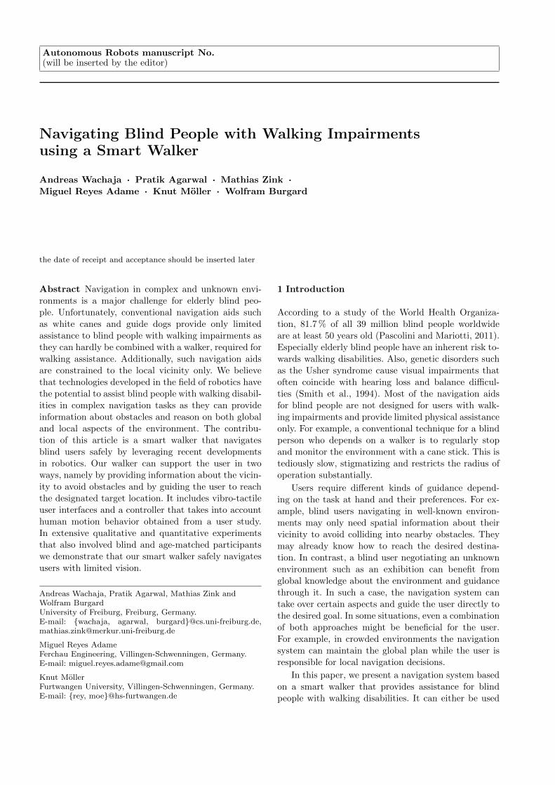
Vibrating handles
Tilting laser
Fix laser
Data processing
Fig. 1 The smart walker is an off-the-shelf walker retrofittedwith our processing and sensor unit, which consists of twolaser range scanners for perception and a standard notebookto perform all the required computation. Two vibrationmotors, which are attached to the handles, provide tactilefeedback.
in the spatial information setting for sensing local ob-
stacles or in the guided navigation setting for reachingthe desired goal. The walker uses vibro-tactile signals tocommunicate obstacle information or navigation com-
mands to the user. We rely on haptic feedback insteadof auditory signals to allow the blind users to use theirhearing for other purposes such as communication andorientation.
Our approach applies robotic techniques for the pur-pose of giving navigation guidance to human users. Theinteraction of the navigation modules with the user
requires additional considerations compared to typicaluse cases in a robot. For example, humans take a longertime to react. A delay in reaction exists between the
perceived navigation command in the form of a vi-bration signal and the resulting action. Also, humansare not as good as robots in accurately following com-mands. Finally, human users are less good than robots
in performing accurate turns.
This article is a substantial extension of previouswork (Reyes Adame et al., 2015; Wachaja et al., 2015).We outline the overall system of our smart walker andexplain the different feedback modes and navigationsettings. Furthermore, we derive a model of the hu-man motion with the walker based on recorded tra-jectories and use this model to design a controller thatconsiders human characteristics. Finally, we evaluateour controller and both navigation settings in combi-
nation with different feedback devices with extensiveuser studies which also include blind and elderly partic-ipants. The results demonstrate that our smart walkeris suitable for safely and reliably providing both spatialinformation and navigational guidance to blind users
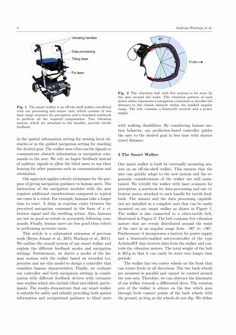
Front
45⁰
Fig. 2 The vibration belt with five motors to be worn bythe user around the waist. The vibration pattern of eachmotor either represents a navigation command or encodes thedistance to the closest obstacle within the marked angularrange. The belt contains a bluetooth receiver and a powersupply.
with walking disabilities. By considering human mo-tion behavior, our prediction-based controller guides
the user to the desired goal in less time with shortertravel distance.
2 The Smart Walker
Our smart walker is built by externally mounting sen-
sors on an off-the-shelf walker. This ensures that theuser can quickly adapt to the new system and the er-gonomic considerations of the walker are still main-tained. We retrofit the walker with laser scanners for
perception, a notebook for data-processing and one vi-bration motor attached to each handle for tactile feed-back. The sensors and the data processing capabili-ties are installed as a complete unit that can be easilymounted on our smart walker as shown in Figure 1.The walker is also connected to a vibro-tactile belt,illustrated in Figure 2. The belt contains five vibration
motors that are evenly distributed around the waistof the user in an angular range from −90◦ to +90◦.Furthermore, it incorporates a battery for power supplyand a bluetooth-enabled microcontroller of the typeArduinoBT that receives data from the walker and con-trols the vibration motors. The total weight of the belt
is 385 g so that it can easily be worn over longer timeperiods.
The walker has two caster wheels on the front thatcan rotate freely in all directions. The two back wheelsare mounted in parallel and cannot be rotated aroundthe yaw-axis. Therefore, we can abstract the kinematicof our walker towards a differential drive. The rotationaxis of the walker is always on the line which goesthrough both contact points of the back wheels withthe ground, as long as the wheels do not slip. We define

Navigating Blind People with Walking Impairments using a Smart Walker iii
Fixed Laser Tilting Laser Servo Motor
Laser ScanMatcher
Point CloudAssembler
TerrainClassification
Localization and Path Planning
Controller
VibrationHandles
VibrationBelt
VibrationHandles
VibrationBelt
ObstacleDetection
Classification
VibrationHandles & Belt
Point cloud
Grid map with obstacles
Next waypoint
Sensor Fusion
Spatial Information Guided NavigationSetting
Mode
Fig. 3 Hardware (dark blue) and software (light blue) architecture of the smart walker. Our system provides two basic settings.In the spatial information setting, the walker detects and relays positive and negative obstacles in the vicinity of the user viavibration motors in the handles or a vibration belt. The guided navigation setting navigates the user to a desired goal underthe consideration of a map and the detected obstacles. Vibration signals from the belt or from the handles guide the user onthe planned path. A third mode for guided navigation combines both feedback devices. In this mode, our walker guides theuser on a path which is planned based on information from the static map only. Furthermore, the user perceives informationabout local dynamic obstacles through the vibration belt. In this way, the user is able to follow a global plan created by thewalker but still has the freedom to make individual local navigation decisions such as how to avoid dynamic obstacles.
the reference-frame with its origin in the middle of the
contact points, the x-axis pointing forward and the z-axis perpendicular to the ground.
An overview of our system architecture is presentedin Figure 3. Our software is based on the ROS frame-work (Quigley et al., 2009). We use two 2D laser range
finders for perception and estimation of the ego-motion.The first laser scanner, a Hokuyo UTM-X002S, is fixedwith respect to the walker and it is used to computethe ego-motion by laser scan matching (Censi, 2008).Additionally, we create a 3D model of the environmentusing a second laser scanner, a Hokuyo UTM-30LX,that is continuously tilted up and down by a servo
motor.
Our approach leverages terrain classifiers to detectpositive and negative obstacles, such as sidewalks anddownward stairways, from point clouds. Specifically, wemodified the “height-length-density” (HLD) classifier,which determines safe and traversable cells for robots(Morton and Olson, 2011). Our modification improvesits suitability to human motion with a walker in tight
narrow indoor spaces. Reasoning on the full three-di-mensional environment is important as blind peopleoften have difficulties in avoiding head-high obstacles ornegative obstacles. These typically are hard to detectwith standard blind-guides when also using a walker.
The smart walker can adjust to the individual needsof the user both in terms of the desired mode of guid-
ance and the form of vibro-tactile feedback. It can oper-ate in two basic settings, spatial information and guidednavigation. Each setting uses the vibration belt or the
vibrating handles for relaying information.
2.1 Setting 1: Spatial Information
For the first setting, spatial information, the walker de-
tects positive and negative obstacles in the environmentand relays them to the user. Similar to the navigationprocess with a white cane, our system enables the userto perceive obstacles, but the user is responsible forall navigation decisions. The walker informs the uservia the vibration handles or the vibration belt aboutall obstacles in its vicinity. Each vibration motor is
assigned to the closest obstacle within its angular re-gion of 45◦. These regions are marked for the belt inFigure 2. The handles provide a lower spatial resolutionof 180◦ compared to the belt as they can only relaywhether the obstacle is on the left or the right side ofthe user. We use pulse-frequency modulation to encodethe distances in the vibration signal. Lower distancesresult in a higher repetition rate. A motor vibrates

iv Andreas Wachaja et al.
x
x
x
x
S3
S1
S2
G3
G1
G2
Fig. 4 One of our test environments for preliminary exper-iments and the corresponding map with planned paths fromstart positions S to goal locations G. Obstacles not presentduring the map creation process are marked with an x.
continuously as soon as a critical distance threshold isundercut and is turned completely off whenever thereis no obstacle in the range of interest. This is similar tothe parking distance control system of cars. One of themain requirements of blind users was that the signalfor obstacle feedback is easy to perceive. Therefore thesmart walker does not encode the obstacle type in thesignal. We use pulse-frequency modulation and do notvary the vibration intensity for two reasons. First, pre-
liminary experiments indicated that the just-noticeabledifference for vibration intensities is higher and the per-ceived intensity depends on external circumstances such
as the thickness of the clothing layer worn below thebelt. Second, pulse-frequency modulation enables theuser to clearly recognize obstacles which are below the
critical distance threshold as the continuous vibrationis easy to perceive.
2.2 Setting 2: Guided Navigation
The second setting, guided navigation, guides the userto the desired destination. This setting depends on aglobal map of the environment. The walker computes a
safe path and then sends navigation commands to theuser through the vibro-tactile interface. The map is cre-ated with a Rao-Blackwellized particle filter (Grisettiet al., 2007). For large buildings such as offices andnursing homes, existing maps and points of interestcould be stored on a cloud server, so that the walkercan acquire this information autonomously via a Wi-Fi access point. The user could specify target locationsbased on a speech interface. Both the distribution ofmaps and the speech recognition is not a focus of thispaper, as there is a wide range of existing solutionsavailable. We use adaptive Monte Carlo localizationto estimate the pose of the walker in the map (Fox,2003). As the smart walker is an unmotorized off-the-
shelf walker without odometry sensors at the wheels,we use the output of the laser scan matcher for poseprediction.
The planning module relies on both the occupancymap and the traversability information of the height-
length-density classifier. It generates a safe path thatguides the user to a desired destination. Figure 4 il-lustrates an example test course and the correspondingplanned paths. The system provides low-level naviga-tion commands to the user in the form of vibro-tactilefeedback based on the planned path and the currentposition of the user.
We have three different interaction modes, namelyhandles, belt and a combination of both to guide theuser on the computed path.
– Handles: The walker plans a path to the goal underconsideration of static and dynamic obstacles. Itguides the user on the path with navigation com-mands from the handles.
– Belt: The walker plans a path to the goal underconsideration of static and dynamic obstacles. In-stead of the handles, it uses the vibro-tactile belt tocommunicate navigation commands.
– Handles and belt combined: In this mode, our system
uses the handles to guide the user on the desiredpath. In contrast to the first mode, our planneronly incorporates information of the static map. Dy-
namic obstacles are conveyed by the belt which op-erates as described in the spatial information set-ting.
In the handles and the belt mode, both the localnavigation and the global navigation are handled by
the walker at the cost of a reduced autonomy of theuser. In the third mode, the walker still creates a globalplan, but it is left to the responsibility of the user
to avoid dynamic obstacles. Therefore, we increase thecontextual knowledge of the user based on the obstaclefeedback signals from the vibration belt. We assumethis mode may be preferred by users as they are more
involved in the decision making process.The walker guides the user for navigational tasks
with four different vibration signals, namely go straight,
turn left, turn right and goal reached. Each signal isrepeated continuously until it is overwritten by anotherone. In order to create signals which are intuitive andeasily distinguishable, we vary the signal pattern inaddition to the location of the signal:
– Go straight: Pulsed vibration on both motors (han-dles) or the front motor (belt). After an on-cycle of100 ms, the motors are turned off for 400 ms.
– Turn left / right:– Handles: Continuous vibration on the left or right
vibration motor.
– Belt: We enable each motor for 250 ms sequen-tially in a cyclic manner. This results in a clock-wise (right) and anti-clockwise (left) vibratingpattern on the belt that is similar to the SOLO

Navigating Blind People with Walking Impairments using a Smart Walker v
Lα
Without prediction With prediction
Fig. 5 Carrot planner for controlling the walker withoutprediction (left) and with prediction (right). The controllercomputes a reference point on the desired trajectory in a fixedlookahead distance L from the walker. The navigation com-mands are sent to the user based on the angular deviation αbetween the x-axis of the walker (red) and the line betweenthe reference-frame and the carrot position. The prediction-based controller considers the delay in the reaction time ofthe user. It computes the navigation command based on thepredicted pose (box with dashed lines).
ONCE rotational pattern described by Cosgunet al. (2014).
– Goal reached: All motors either of the belt or thehandles are first enabled with 100 % vibration in-tensity, then enabled with 50 % and finally turned
off. Each step is executed with a duration of 500 ms.
2.3 Prediction-Based Controller
The controller module in the guided navigation settingis challenging as humans can only sense and interpret
a limited number of commands and will have a delayin their reaction. An important prerequisite for guidingusers on a path is to understand how humans react to
navigation signals. In particular, we identified the fol-lowing important parameters for guiding humans witha walker on a path:
– Reaction time (tR): Time between the system sendsa navigation command and the user performs thecommand.
– Rotational radius (r): Radius of curvature for thetrajectory resulting out of a turn command.
– Velocities (vstraight , vrot): Velocities of the user whilemoving straight respectively while turning.
The exact values for each of these parameters are ob-tained with a user-study explained in the experimentalsection.
Our controller is based on a modified carrot-followerapproach. We extend the existing approach describedby Hogg et al. (2002) to allow incorporating the pa-rameters described above. Additionally, our modifica-tion makes sure that the path is not followed in thewrong direction in case that the walker is oriented in thewrong way. The carrot-following algorithm estimates a
waypoint on the path in a fixed lookahead distance Lfrom the walker. This waypoint is called the carrot posi-tion. It is calculated by intersecting a circle around thereference frame with a radius that equals the lookaheaddistance L with all path segments (see also Figure 5).We examine the direction vector which indicates thedirection of the path at the intersection point. Sucha point is considered as a potential carrot position incase that this direction vector points away from thecircle. This ensures that the user does not follow thepath in the wrong direction. A new carrot position isonly accepted if its distance from the old carrot positionmeasured over the path length is below a threshold. Asa result, the user follows a self-intersecting path all theway from the beginning to the end and does not choosea wrong carrot position at the intersection of two pathsegments.
Our controller monitors the angular difference αbetween the roll-axis of the walker and the line betweenthe reference-frame and the carrot position. It sends aturn command to the user as soon as |α| > αthresh . We
introduce a hysteresis value αhyst to avoid oscillationwhen α ≈ αthresh . After a turn command was sent, thecontroller switches back to the go-straight command as
soon as |α| ≤ αthresh − αhyst .We state the following three requirements to com-
pute the lookahead distance L and the angular thresh-old αthresh :
1. The walker driving on a straight line parallel to astraight path line commands the user to turn as soonas the distance between the two lines is above a
maximum distance dmax :
L sin (α) ≤ dmax (1)
2. We consider a situation in that the user is driving ona straight path line towards a rectangular corner of
the path. Under the assumption that the user has nodelay and turns with the walker with a fixed curveradius r, the turn command has to be sent as soonas the distance between the user and the corner ofthe path equals r:
L cos (αthresh) = r (2)
3. The lookahead distance should be chosen as high aspossible within the first two constraints in order two
avoid oscillation.
From these requirements we can derive suitable val-ues for the lookahead distance L and the angular thresh-
old αthresh :
L =r
cos (αthresh)(3)
αthresh = arctan
(dmax
r
)(4)

vi Andreas Wachaja et al.
2.5m 2.5m 2.5m10
m2.5m
Start
Goal
Course 1 Course 2 Course 3 Course 4
(a) Obstacle courses
Participant number
1 2 3 4 5 6 7 8 9 10
Number
ofcollisions
0
1
2
3
4
5
6
*
*
Handles
Belt
(b) Average number of collisions
Participant number
1 2 3 4 5 6 7 8 9 10
Tim
e[s]
0
50
100
150
200
*
*
Handles
Belt
(c) Average travel time
Fig. 6 Four configurations of the test course (left) for the evaluation of the spatial information setting with elderly people.The number of collisions per run (middle) and the travel time (right), both averaged over two runs. Nearly all runs resultedin collisions in narrow passages, but, with two exceptions, the participants could reach the goal. We had to cancel two runswith the belt, because the test participants got disoriented and walked back towards the starting point. In this case, the datarefers only to the remaining completed run with the belt and we marked the bar with an asterisk. Both in terms of number ofcollisions and travel time, no feedback mode is clearly preferred.
In its basic version, the carrot planner does not considerthe reaction time tR of the user. As we explained earlier
this delay can cause significant guidance errors. There-fore, we extend our carrot planner with a predictionmodule that predicts the pose of the walker at the timet0 + tR, where t0 is the current point in time. This
is a technique commonly used when handling delaytimes in systems, for example Engel et al. (2012) usethis method to handle delay times caused by off-board
computations. We consider a constant velocity modeland the navigation commands sent in the time range[t0 − tR; t0] to predict the specific pose of the walker,
which is relevant for the current navigation decision (seeFigure 5).
3 Experiments
We evaluated the performance of our smart walker insix experiments both qualitatively and quantitatively.We test individual modules as well as the whole sys-tem in an end-to-end manner. The first experiment isthe evaluation of the spatial information setting withblindfolded age-matched participants. In the followingthree experiments, we determined parameters of theprediction-based controller for guided navigation, eval-
uated the performance of this controller and differentmodes of application. These three experiments involvednormally-aged participants without visual impairments.The last two experiments evaluate our smart walker inboth settings with blind test participants.
3.1 Spatial Information for Elderly People
We tested the capabilities of the smart walker to pro-vide spatial information regarding nearby obstacles to
elderly people. Furthermore, the aim of these experi-ments was to assess the reliability of our positive andnegative obstacle detector. These experiments allowedus to gain insights into whether elderly people are able
to perceive the vibration signals distinctly and whetherthey prefer the handles or the belt as a tactile feedbackdevice. We evaluated our system with ten participants,
of which six were females and four were males. Theage of the participants ranges from 65 to 80 years. Oneparticipant was blind (number 10), the other nine par-
ticipants were blindfolded during the experiments. Allparticipants had no prior experience with the walker.
In the first experiment we set up a 10 m long testcourse containing several boxes as obstacles (see Fig-ure 6(a)). After a short introduction to our system
and 5-10 minutes of training the participants traveledblindfolded from one end to the other only relying onthe haptic feedback. Each participant performed fourruns, two with vibration feedback from the handles andtwo runs with vibration feedback from the belt. Werandomized the order of runs and varied the positionsof the obstacles between each run to avoid any bias.
Figure 6(b) shows the number of collisions for beltand handles mode averaged over both runs. Nearly allruns resulted in collisions in narrow passages but, withtwo exceptions, the participants could reach the endof the 10 m long course. We had to cancel two runswith the belt, because the test participants got dis-oriented and walked back towards the starting point.
Both participants had one collision before their runwas canceled. For these participants, we report only

Navigating Blind People with Walking Impairments using a Smart Walker vii
Handles Belt
Numberofruns
0
5
10
15Collisions
No collision
Collision
Fig. 7 The test environment with a head-high obstacle for the spatial information experiment (left), resulting point cloudcaptured by the tilting laser scanner and a model of our walker (middle left) and obstacle map created by the height-length-density classifier (middle right). The white areas in the map are classified as safe to traverse, the black areas are classified asobstacles and the medium gray areas are classified as unknown or uncertain terrain. The participants required a longer timeto perceive the obstacle signal from the belt, which resulted in a higher number of collisions (right).
Handles Belt
Numberofruns
0
5
10
15Collisions
No collision
Collision
Fig. 8 Test person in our spatial information experiment walking towards a downward stairway which is a typical negativeobstacle (left). The height-length-density classifier uses the point cloud (middle left) to detect the hazardous areas and marksthem in a map (middle right). The success rates for the recognition and avoidance of the negative obstacle are on the right.
the result of the remaining completed run with thebelt in Figure 6(b) and Figure 6(c). An asterisk marksthe corresponding bars. Figure 6(c) illustrates the av-
erage travel time per run. Based on the observations,no feedback mode is clearly preferred. We attributethe slow walking speed mainly to the fact that the
participants required additional time to interpret thevibration signals. Therefore, we expect the travel timeto decrease when the users become more familiar withthe system.
The purpose of the next two experiments was to
assess the performance of the detector for positive andnegative obstacles. We used a barricade tape to createa head-high obstacle as illustrated in Figure 7 and adownward stairway as a negative obstacle (Figure 8).The participants were asked to walk towards both ofthese obstacles and stop as soon as the vibration signalinformed them that they were directly in front of theobstacle. Each obstacle was evaluated once with feed-back from the handles and once with feedback from thebelt. All participants completed these experiments.
Figure 7 and 8 illustrate that around half of theparticipants had trouble avoiding the obstacles with thetactile belt. In contrast, most participants could suc-cessfully avoid both obstacles with the vibrating han-
dles. This was also confirmed with the questionnaire-based interview conducted after the participants had
finished all three experiments (Figure 9). Most of theparticipants stated that they had trouble sensing thevibration signals from the tactile belt. We believe this
is because hands are more sensitive to vibrations com-pared to the abdomen (Wilska, 1954). Furthermore theparticipants had difficulties to determine the locationof a vibration source in the runs with the belt. The
vibration signals on the belt were more challenging tosense for the users (see Figure 9), but this did not resultin a significant increase in the number of collisions in thetest course. We are currently in the process of designinga belt with stronger vibration motors. An interestingtopic for future work is the development of trainingmethods, which enable the users to better understand
the relationship between obstacle positions and vibra-tion signals.
The participants would use the smart walker in caseof walking disabilities and vision impairments in orderto maintain social contacts and increase the autonomy.Several participants stated that the product price ofthe smart walker should be affordable. While the choiceof an unmotorized off-the-shelf platform considers thisconcern, we are currently testing configurations that re-duce the costs of the sensor setup and still work reliablyindoors and outdoors.
This first experiment shows that our system suc-
cessfully provides functionalities that are beyond the

viii Andreas Wachaja et al.
Handles Belt
Number
ofparticipants
0
5
10
15Strongly agree
Rather agree
Cannot assess
Rather disagree
Strongly disagree
Handles BeltNumber
ofparticipants
0
5
10
15Strongly agree
Rather agree
Cannot assess
Rather disagree
Strongly disagree
Handles Belt
Number
ofparticipants
0
5
10
15Strongly agree
Rather agree
Cannot assess
Rather disagree
Strongly disagree
“I could clearly sense thevibration signals.”
“The handling of the walkerwas easy.”
“I felt safe while walking inthe obstacle course with the walker.”
Fig. 9 Results of the qualitative evaluation for the spatial information experiment. We asked the participants to rate threestatements on a Likert Scale at the end of the evaluation. Half of the participants stated that they had difficulties to sense thevibration signals of the belt (left). With the exception of one test participant, all users found our system to be rather easy orvery easy to handle (middle). More than 75 % of the users stated that they felt safe while traveling with our system (right).
time [s]
5 6 7 8 9 10
theta[rad]
-1
-0.5
0
0.5
1
(a) Reaction time
x [m]
-4 -3.5 -3 -2.5
y[m
]
-1.5
-1
-0.5
0
(b) Rotational radius
time [s]
0 5 10 15 20
distance[m
]
-1
0
1
2
3
4
5
6
(c) Velocities
Fig. 10 Results from one run of the experiments for obtaining the parameters of the prediction-based controller. We directedthe participant to move straight and then turn when one of the handles vibrates. The point at which the turn-signal is sent tothe participant is marked with a cross sign in all the figures. The left image illustrates that we compute the delay in reactiontime of the user by measuring the difference in time between the signal sent (cross) and the change in orientation (intersectionof the dotted lines). The center image illustrates the rotational radius computed by fitting a circle (dotted lines). The rightimage illustrates the two distinct velocities. The solid line depicts the actual user trajectory while the dotted lines representthe best model fit based on k-means clustering and least square estimation.
capabilities of a classical white cane. It can inform usersabout head high obstacles and it reduces the numberof object contacts required to explore the environmentto a minimum. This is important in all environmentswhere obstacle contacts can potentially cause damage.Our experiments indicate that the vibration signals ofthe handles are easier to perceive and better suited forwarning the user of dangerous obstacles.
So far in all of our experiments we start sendingproximity warnings as soon as the obstacles are withina fixed distance. This does not consider delay in humanreaction or the walking speed of the user. Such factors
become even more important when the walker is usedin the guided navigation mode. The experiments in thenext section model such human-specific characteristicsand incorporate them into our prediction-based con-troller.
3.2 Parameter Estimation for Guided Navigation
The goal of our second experiment was to identify theparameters for the prediction-based controller outlinedin Section 2.3. Ten test participants were blindfoldedand asked to move straight till a vibration-feedback onone handle directed the participant to stop and turnon the spot either in the left or the right direction
depending on the signal. We instructed the participantsto turn on the spot to avoid generating trajectorieswith large radius in order to facilitate navigation innarrow passages. The participants were between theages of 22 and 28 years. All participants were maleand did not have any walking disabilities. They werefirst allowed to get familiar with the walker and vi-bration feedback. Once the participants were familiarwith the setup we collected ten evaluation runs per

Navigating Blind People with Walking Impairments using a Smart Walker ix
Table 1 Estimated parameters for the prediction-basedcontroller.
Parameter Mean (std-dev)
Reaction time tR [s] 0.87 (±0.20)Rotational radius r [m] 0.36 (±0.25)Straight velocity vstraight [m/s] 0.44 (±0.15)Velocity during rotation vrot [m/s] 0.18 (±0.08)
participant to obtain the parameters of the prediction-based controller. A motion capture system tracked theposition and orientation of the walker over time and wefused this data with the navigation signals. Figure 10illustrates exemplary results from one run.
For calculating the reaction time per run, we con-sider the orientation of the walker over time. K-meansclustering was used to fit two lines which approximatethe rotation velocity before and during the turning pro-cess. The intersection point of these lines marks thepoint in time where the user reacts to the signal andactually turns. The reaction time is the difference be-tween the signal sent to the user and the walker being
rotated. This is further illustrated in Figure 10(a). Thecross mark is the time at which the turn signal was sentto the user while the intersection of the dotted lines
estimates when the user actually turned the walker.
To calculate the rotational radius we fit a circle tothe rotational trajectory using a least square minimiza-tion technique. The radius of the circle is the approxi-
mated rotation radius. Figure 10(b) illustrates the circlefit to the trajectory. The velocity of the user in bothsituations, while going straight and while turning, is
computed with a similar k-means method as the oneused to estimate the reaction time. The dotted linesin Figure 10(c) illustrate the straight and rotationalvelocities.
The parameters computed from this experiment canbe found in Table 1. The estimated reaction time is al-most 1 second. This is much more than that of a typical
robot setup. Hence, we believe that incorporating thereaction time of a human user is a key for improvingthe guidance process. For example, if the reaction timeis not considered, the user could overshoot the goal bymore than 35 cm based on the typical straight velocityof a participant. The rotational radius is also importantfor guiding a human on the desired path and to predict
the current position. Our experiments indicate that theestimated parameters vary from individual to individ-ual and we expect that these parameters correlate withthe age of the user, the level of visual impairment andthe level of walking impairment. For example, elderlyusers tend to have increased reaction times (Der andDeary, 2006). Therefore, we are currently working ona quick and easy-to-use calibration procedure which
-4 -2 0 2 4
-2
0
2
-4 -2 0 2 4
-2
0
2
Path 1 Path 2
-4 -2 0 2 4
-2
0
2
-4 -2 0 2 4
-2
0
2
Path 3 Path 4
Fig. 11 The four randomly generated paths which we usedfor the evaluation of our prediction-based controller. Thestart point is marked with x. Path 1 and Path 2 contain onlystraight lines joined at right angles. This simulates indoorenvironments. Path 3 and Path 4 have segments joining witharcs and lack an orthogonal structure to simulate complexoutdoor environments. All units are in meters.
enables the walker to automatically detect and adjustthe controller parameters according to individual user
behavior.
3.3 Controller Performance for Guided Navigation
We conducted a user study with eight blindfolded par-ticipants to evaluate the advantages of the prediction-
based controller compared to a standard carrot-followercontroller without any prediction. Our study includedtwo female and six male participants, all within the age
group of 22 to 30 years. We set the reaction time ofthe user tR to 0.87 s and the rotational radius to 0.36 mbased on the estimated system parameters in Table 1.These values were used to determine the parameters for
the carrot planner. The hysteresis value αhyst is set to5◦ and dmax set to 0.09 m. This results in αthresh of 14◦.The lookahead distance L is rounded to 0.35 m.
For this evaluation, we generated six random paths.Half of the paths consist of lines connected at rightangles simulating indoor environments. The other halfof the random paths contain lines and arcs which areconnected with varying angle. This simulates typicaloutdoor trajectories. Out of the six paths, we used twoto train the participants and the other four paths forevaluation. Figure 11 provides an overview of the paths,which were all 30 m in length to allow comparable re-sults.
We provided each participant with a short intro-duction to the smart walker and the guidance signals

x Andreas Wachaja et al.
1m
(a) Path Comparison
Participant number
1 2 3 4 5 6 7 8
l p−l n
p[m
]-6
-4
-2
0
2
4
6
Path 1
Path 2
Path 3
Path 4
(b) Difference in distance traveled
Participant number
1 2 3 4 5 6 7 8
t p−t n
p[s]
-100
-50
0
50
100
150
Path 1
Path 2
Path 3
Path 4
(c) Difference in travel time
Fig. 12 The left figure shows the ground truth path (dashed line) and the trajectories of one participant with the differentcontrollers. The start point is marked with a circle. It can be seen that the controller without prediction (dark purple line)results in a trajectory that oscillates around the ground truth path and overshoots at the corners. Both effects are reducedby our prediction-based controller (light turquoise line). The difference in trajectory length l (center) and in travel time t(right) illustrate that the prediction-based controller (subscript p) results in shorter trajectories and results in reaching thegoal faster compared to the standard controller (subscript np). Negative values indicate shorter distance and lesser time forthe prediction-based controller.
followed by two training runs. After the training, every
test person completed the remaining four paths twotimes each, once with the prediction-based controllerand once with the controller without prediction. The
order of paths and controllers were randomized. Forthe purpose of quantitative evaluation, we tracked thetrajectory of the test person using a motion capturesystem. The use of motion capture eliminates any errors
in the evaluation due to mistakes in the mapping andlocalization system. Additionally, after every run thetest person graded the guidance style on a scale from
1 (very bad) to 10 (excellent).
Figure 12(a) illustrates the desired path that theparticipant is guided along and the trajectories result-
ing from the two controllers. The controller withoutpose prediction oscillates around the ground truth pathand often overshoots at the corners. This is also illus-trated in Figure 12(b) where we compare the length
of each trajectory pair per participant and path. Wecan see that the length of the trajectories resultingfrom our controller with prediction which considers thereaction time of the user is shorter compared to thecontroller without prediction in 25 out of 32 cases. Weconducted three paired-samples t-tests to compare theperformance of both controllers based on the trajec-tory lengths, the time of travel and the average pathdeviation. There is a very significant difference in thetrajectory lengths resulting from the controller withprediction (M = 30.1 m, SD = 1.55 m) and the tra-jectory lengths of the standard controller (M = 31.3 m,SD = 1.59 m); t(31) = −3.51, p = 0.0014. Also the
difference in the time required for the user to reachthe goal on the desired path is significantly different
(prediction-based controller: M = 193.2 s, SD = 40.9 s,
standard controller: M = 211.7 s, SD = 33.2 s); t(31) =−3.16, p = 0.0035, see also Figure 12(c). These resultssuggest that the prediction-based controller enables theusers to reach their goal on a shorter path in less time.
The mean-deviation from the desired trajectory alsohelps to compare the performance of both the con-trollers. The deviation was calculated by choosing equi-
distant points on the desired trajectory and then com-puting how far the user was from this point using boththe controllers. We fail to reject the null hypothesis
that there is no difference between both controllers re-garding the path deviation at a significance level ofα = 0.01 (prediction-based controller: M = 0.065 m,SD = 0.020 m, standard controller: M = 0.055 m, SD =
0.022 m); t(31) = 2.42, p = 0.021. We believe that theslightly increased path deviation of the prediction-basedcontroller stems from the fact that the user oscillates
less around the ground truth path with this controller.
The improved path guidance performance for thecontroller with prediction comes at the cost of a higherfrequency of navigation signal changes, as can be seenin Figure 13(a). Also, the qualitative evaluation revealsthat the participants preferred the controller withoutprediction (see Figure 13(b)). As a few participantsstated, this was mainly due to the fact that the con-troller with prediction caused a high number of signalchanges which could not always be interpreted clearly.
This result is in contrast to the improved path guid-ance performance in terms of resulting path length andtrajectory execution time. In average, the traveled pathwas 4 % shorter and the participants saved 9 % of traveltime with our controller. We believe that these results

Navigating Blind People with Walking Impairments using a Smart Walker xi
Path 1 Path 2 Path 3 Path 4
Signalchanges
per
second
0
0.5
1
1.5
2
Without Prediction
With Prediction
(a) Signal Changes
Length Time User Preference
Number
oftrials
0
5
10
15
20
25
30
35
Without Prediction
With Prediction
(b) Controller Preference
Fig. 13 Left: Comparison of the prediction-based controllerwith the non-prediction-based controller. The mean numberof navigation signal changes per second for the four differentpaths (left). The controller with prediction relays a higherfrequency of navigation commands compared to a controllerwithout prediction. Path 3 and Path 4 require a higherfrequency of signal changes, which is a result of the morecomplex path geometry. Right: Number of trials in whichthe prediction-based controller performs better than thestandard one in terms of traveled path length (shorter better),travel time (quicker better) and user preference (higher scorebetter).
which we acquired with healthy test persons can also betransferred to elderly people with walking disabilities.
On one hand these users tend to walker slower but onthe other hand they also suffer from increased reactiontimes (Der and Deary, 2006) that motivate the needfor the prediction-based controller. The results of this
experiment indicate a correlation between the user pref-erence and the number of signal changes of a controller.We will consider this finding in future versions of the
prediction-based controller.
3.4 Application for Guided Navigation
In this section we evaluate the guidance provided byour smart walker in a complete end-to-end manner. Theobjective is to verify if we can use the smart walker tonavigate users safely to the desired goal. We also wantto gain insights into the advantages and disadvantagesof the three different guidance modes, namely handles,
belt and a combination of both.
For the evaluation we used a setup that resembles acomplex indoor environment. It contained walls, objectson the floor and one dynamic obstacle in the form ofone person walking around in the course. For theseexperiments we did not rely on the tilting laser as theindoor test environment was free of negative obstacles.We identified three pairs of start and goal locations asshown in Figure 14. The first pair of locations (S0, G0)was used for training the test participants while theother two pairs were used for evaluation. During thetraining phase, each test person completed three runsfrom S0 to G0, one in each mode (handles, belt and
G0
G1
G2
S0
S1
S2
Fig. 14 Test environment (left) and its map (right) used forthe guided navigation experiments. We defined three pairs ofstart (circle) and goal (cross) locations. The first pair (S0, G0)is for training while the remaining two pairs are used forevaluation. The size of our environment is 8 m x 8.25 m.
combined). After the training is over, participants werenavigated on the remaining two tracks once in each ofthe three modes. The order of tracks and modes wasrandomized to avoid any bias. After each run, the super-visor guided the participant to the next start position.Per run, we confronted the test participants with onedynamic obstacle, a human which stepped into the wayof the participant. This is important as any realistic
scenario will always contain some form of dynamic ob-stacles. Ten people in the age of 22 to 30 years, all male,took part in this study. We blindfolded all test persons
and equipped them with acoustic earmuffs so that theycould not hear noises caused by the dynamic obstacle.This ensured that the participants relied only on oursystem for obstacle avoidance, as might be necessary
in noisy environments, e.g. when walking next to mainstreets. The prediction-based controller was used forall our experiments. For each test run, we tracked the
path of the participant to the goal while measuring thetime, distance and number of collision encountered onthe way.
A series of images in Figure 15 shows one participantguided in the test environment avoiding both static
and dynamic obstacles. The participant bypasses allobstacles safely and also avoids the dynamic obstaclesuccessfully, as the planner incorporates it into an up-dated path.
The logged paths for one participant can be seenin Figure 16. For all paths, using the handles resultedin the smoothest trajectory. The belt mode tended tocause abrupt and large changes in orientation. This iscaused by most participants requiring more time tointerpret the turn signal, causing them to stop and turnon the spot. The majority of participants recognized thedynamic obstacle in the combined mode based on thebelt signals but had trouble to find a detour path ontheir own. For example, as illustrated in Figure 16, the
test person recognized the obstacle in Path 0, but thechosen path resulted in a collision. We anticipate that

xii Andreas Wachaja et al.
Fig. 15 An exemplary evaluation run in the test environment for the guided navigation experiments. The participant startsfrom the lower left corner and is guided towards the goal position in the upper right corner. Our system navigates the useraround a dynamic obstacle that blocks the direct path of the user.
Handles
Belt
Combined
Path 0 (Training) Path 1 Path 2
Fig. 16 Logged paths of the training (left) run, the first (middle) run, and second (right) run for one participant in the guidednavigation experiments. The start locations are marked with a circle, the goal locations with a cross. Some of the deviationsbetween the paths are caused by the human dynamic obstacle. For all three paths, the handles resulted in the smoothesttrajectory. In the combined mode, the participant had trouble to avoid the dynamic obstacle in Path 0 and Path 2 as theparticipant sensed the obstacle but had to develop the obstacle avoidance strategy on his or her own.
Handles Belt Combined
Numberofruns
0
5
10
15
20
25
30
No collision
1 collision
≥ 2 collisions
Fig. 17 Number of collisions per run for the guided nav-igation experiments. Majority of the collisions occurred inthe combined mode. These collisions often resulted in uncon-trolled correction-movements which caused further collisions.The belt resulted in the highest number of collision-free runsbut also required the longest travel time.
this combined mode may be helpful with more trainingand if the user is familiar with the environment.
Figure 17 provides an overview of the number ofcollision-free runs. Both the belt and the handles moderesulted in a low number of collisions compared to the
combined mode. Around 50 % of the runs in the com-bined mode had at least one collision. These collisionswere caused due to the change in the local navigationstrategy, which required the user to understand andinterpret the obstacle vibration signals from the beltcarefully. The traveled distances are illustrated in Fig-ure 18. Except of a few outliers, there was no significantdifference between the path lengths. This shows thatall of our three guidance strategies were able to guidethe user from start to goal without larger detours. Thetravel time per path reveals differences in the perfor-mance of our three modes (see Figure 19). The handlesmode guided all participants in the shortest time. Thebelt mode was slower than the combined mode in all but
one case, which seems contrary to our observation thatthe users typically required a longer time in the com-

Navigating Blind People with Walking Impairments using a Smart Walker xiii
Participant number
1 2 3 4 5 6 7 8 9 10
Length
l p1[m
]
0
10
20
30
40
50Handles
Belt
Combined
Participant number
1 2 3 4 5 6 7 8 9 10
Length
l p2[m
]
0
10
20
30
40
50Handles
Belt
Combined
Participant number
1 2 3 4 5 6 7 8 9 10
Length
l p1+l p2[m
]
0
10
20
30
40
50Handles
Belt
Combined
Path 1 Path 2 Path 1 and Path 2 combined
Fig. 18 The distance traveled for first path (left), second path (center) and combined (right) per participant and mode forthe guided navigation experiment. The figures illustrate that all three modes are able to guide the users to the destination.
Participant number
1 2 3 4 5 6 7 8 9 10
Tim
et p
1[s]
0
100
200
300
400
500
600Handles
Belt
Combined
Participant number
1 2 3 4 5 6 7 8 9 10
Tim
et p
2[s]
0
100
200
300
400
500
600Handles
Belt
Combined
Participant number
1 2 3 4 5 6 7 8 9 10
Tim
et p
1+t p
2[s]
0
100
200
300
400
500
600Handles
Belt
Combined
Path 1 Path 2 Path 1 and Path 2 combined
Fig. 19 The travel time for first path (left), second path (center) and combined (right) per participant and mode for theguided navigation experiment. For every participant, navigation with handles resulted in the shortest total travel time. Exceptfor one participant, the travel time in the combined mode was lower than the travel time in belt mode.
bined mode to detour the dynamic obstacle. This canbe explained by the fact that most of the participantsrequired more time to interpret the turn commands ofthe belt correctly. The user rating (Figure 20) reflects
this result as well. All but one participant preferredthe handles mode. The combined mode was preferredover the belt mode, even though this mode resultedin a higher number of collisions. As Figure 21 shows,there is a correlation between the understandability ofthe navigation command and the user preference. Inter-
estingly, feedback from test participants revealed thatsome participants liked the combined mode better asthis mode provided them with an increased contextualknowledge of their surrounding.
A summary of our findings is shown in Table 2. Boththe handles and the belt mode guide the user after aminimal training time with a low collision risk to thegoal. The belt mode resulted in increased travel timesas the navigation commands are harder to perceive.While the combined mode has a higher collision risk,the participants appreciated the contextual knowledgeprovided by the belt.
Participant number
1 2 3 4 5 6 7 8 9 10
Participantrating
012345678910
Handles
Belt
Combined
Fig. 20 User rating from 1 (very bad) to 10 (excellent) perparticipant and mode for the guided navigation experiment.Each value is averaged over the participant’s rating forPath 1 and Path 2 in the same mode. With one exception,all participants preferred the navigation by handles. Themajority of the participants rated the combined mode betterthan the belt mode even if this mode resulted in a highernumber of collisions.
3.5 Evaluation with Blind Users
While we evaluated basic technical functionality of thesmart walker with blindfolded participants, we also con-tinuously considered the feedback of blind users andmobility teachers in our development process. This isimportant, as there are differences between navigation

xiv Andreas Wachaja et al.
Handles Belt Combined
Number
ofparticipants
0
2
4
6
8
10
12
14
16
18
Strongly agree
Agree
Neutral
Disagree
Strongly disagree
Handles Belt Combined
Number
ofparticipants
0
2
4
6
8
10
12
14
16
18
Strongly agree
Agree
Neutral
Disagree
Strongly disagree
Handles Belt Combined
Number
ofparticipants
0
2
4
6
8
10
12
14
16
18
Strongly agree
Agree
Neutral
Disagree
Strongly disagree
“I could clearly distinguish betweenthe four different navigation signals.”
“The handling of the walkeris intuitive.”
“I felt safe while usingthe walker.”
Fig. 21 Qualitative evaluation for the guided navigation experiment. We asked the participants at the end of the experimentto rate three statements on a Likert Scale. Several participants had trouble to distinguish between the different navigationcommands in the belt mode (left). In contrast, the participants could clearly distinguish the navigation commands in thehandles mode (left). They stated that the handling of the walker felt intuitive (middle) and they felt safe while using oursystem(right).
Table 2 Summary of results of the guided navigation experiment. The results show that both the belt and the handles areable to guide the user to the desired goal. Additionally, it illustrates that the users are much faster and travel shorter distanceswhen using the vibration handles.
Mode Handles Belt Combinedmean std-dev mean std-dev mean std-dev
Path length [m] 11.6 0.8 12.8 2.5 12.7 2.7Travel time [s] 80.8 23.5 150.9 52.5 109.1 40.3User rating 8.3 1.0 4.7 2.1 6.1 1.8
Collision-free runs 90 % 95 % 45 %
methods used by sighted and blind users (Williams et al.,2014).
3.5.1 Exploratory Evaluation
We presented an prototype of our smart walker at Sight-City 2014 and SightCity 2015, Germany’s biggest ex-hibition about aids for the blind (sig). This was anexploratory evaluation where around 30 visitors testedour system. Most of these visitors were either visually
impaired or worked as mobility teachers. The visitorsassessed our walker in the spatial information settingfor a few minutes in the crowded exhibition floor. Af-terwards, we asked them for feedback regarding the us-ability of the system, the quality of the vibration signalsand potential improvements. Six visitors additionallyanswered a detailed anonymous questionnaire.
The results from this early evaluation indicate thatour walker enabled the participants to successfully iden-tify obstacles in their environment. One of the maingoals of this evaluation was to analyze if blind usersacross all ages could sense the vibration feedback sig-
nals. Most of the participants stated that they were ableto identify the haptic signals clearly and felt safe while
using our system. People who had problems to iden-tify the vibration signals mostly stated that this was
a sensitivity-related issue. Either the vibration signalswere considered too intense (e.g. when the participanttested the belt and was ticklish around the waist) or theparticipant could not sense the vibration signals well.
Most problems were related to the vibration belt. Thetest participants expressed that our smart walker waseasy to adapt to, requiring only a few instructions. Ad-
ditionally, the capability to robustly identify negativeobstacles was highly appreciated as available electronicblind assistances are limited in this regard. Suggestionsincluded the introduction of semantic obstacle feedbackand additionally allowing the distinction between posi-tive and negative obstacles. We are planning to incorpo-rate this type of feedback in future versions of the smartwalker. While the participants could avoid obstacles,they had trouble to estimate the exact position anddimension of obstacles. This was specifically a drawbackwhen navigating in narrow spaces and motivates ourapproach towards guided navigation. Overall, the out-come of this exploratory evaluation supports the resultsof our experiments with the age-matched user group in
Section 3.1.

Navigating Blind People with Walking Impairments using a Smart Walker xv
Fig. 22 Blind user and the experimenter in the test environ-ment for the pilot study. The participant is currently walkingon the main floor. Two small floors and the adjacent roomscan be seen in the background.
3.5.2 Pilot Study
We designed a pilot study with the aim to understandhow well the overall system is accepted by blind peo-ple and how the smart walker compares to conven-tional navigation techniques. The participant of ourpilot study was a 69 years old male who is completely
blind. He uses a white cane since fourteen years and didnot have any prior experience with the smart walker.We setup a test course which resembles an office envi-
ronment with one large main floor, three small floorsand one room attached to each small floor as shown inFigure 22. The test course has a size of 12.5 m x 6.0 m.The smart walker setup was identical to the one de-
scribed in Section 3.4. Initially we introduced the par-ticipant to all navigation modes of the smart walker.As a first test, we asked the participant to explore
the environment in the setting spatial information, firstwith the vibrating handles and then with the vibrationbelt. The main outcome of this experiment is:
– The participant was able to explore the main floorsafely and successfully using the spatial informationsetting. He had trouble finding the openings of thesmaller corridors and the doors to the rooms in thissetting.
– The participant preferred the vibration handles overthe vibration belt, as he felt that the vibration sig-
nals from the handles were easier to perceive.
In order to evaluate the guided navigation settingthe participant traveled four different routes from themain floor to the rooms in randomized order, each routetwice, once with the smart walker and once with hisconventional white cane. In the runs with the walker,we used the vibrating handles, as the participant pre-ferred this mode in the previous experiment. Beforethe runs with the white cane, the experimenter pro-vided a sequence of oral direction instructions. In twoevaluation runs, the experimenter had to repeat single
instructions, because the participant could not remem-ber them. The experimenter noted the remarks of theparticipant given during the experiment and in a finalinterview. The main findings are:
– In all test runs, the participant reached the goal lo-cation successfully. In average, the participant tookaround twice the time to reach the goal locationwith the walker compared to the runs with his whitecane (walker: M = 77.5 s, SD = 28.8 s, white cane:M = 31.5 s, SD = 12.2 s). The travel time withthe white cane does not include the additional timerequired for the communication of direction instruc-tions (around 20 s). These instructions were not re-quired in the test runs with the walker. The traveltime with the walker is higher, because the userrequired additional time to interpret the navigationsignals and walked more slowly. We anticipate thatthis difference in travel time will be reduced withincreasing familiarization. Moreover, the system isdesigned for blind people with walking disabilities
who need a walker on a regular basis and have typ-ically slower walking speeds in general.
– In general, the participant preferred the guided nav-igation setting over the spatial information setting.
– The participant remarked that one of the potentialrisks of the smart walker technology is a loss oforientation during guided navigation. The walker
should provide semantic information about the cur-rent environment and inform about important guide-lines such as curbs and typical landmarks.
The outcome of this experiment is that the spatialinformation setting is helpful for exploration in wideopen spaces, but is of limited use for navigation innarrow indoor regions. In contrast, the guided navi-gation setting is able to guide blind users successfullyto their goal, as already indicated in the previous ex-periment with blindfolded participants. An important
scope for future work is the integration of semanticenvironmental feedback for better orientation. Overall,these experiments support the previous findings that weacquired in experiments with non-blind participants.
4 Related Work
The area of elderly care and blind assistance has beenresearched extensively throughout the recent past. Sev-eral researchers presented novel robotic walkers, de-signed primarily for elderly non-blind people with walk-ing disabilities. They provide structural support andnavigational assistance at varying levels. Graf (2001) in-troduced Care-O-bot II that is a multi-functional home

xvi Andreas Wachaja et al.
care system for elderly people. The robot moves in adirection desired by the user based on forces measuredat displacement transducers located at the handles. Yuet al. (2003) proposed a motorized walker which aims toguide elderly people with cognitive impairments usingshared-autonomy control. The walker monitors the userand adjusts the autonomy level between user-controland computer-control according to the measured per-formance. The work of Morris et al. (2003) to navigateelderly people with cognitive disability is closely relatedto our smart walker. They guide people with a sharedcontrol robot system where a robot walker is built ontop of a motorized omni-directional robot. The walkerhas two modes of operations – passive or active. In thepassive mode, the robot walker moves in the directionthe user wants it to move. In the active mode, the robotplans a trajectory to a goal and guides the user bydriving along the trajectory. The user of the walkeris pulled forward by the robot and reaches the goalin this way. Glover et al. (2003) presented a walkerretrofitted with motors so that it is able to park itself
and return to the user. The main focus of this work is toreduce the fall risk of an elderly user while walking tothe walker. The guidance style is passive, the walker
displays visual directional hints, but the user finallycontrols the travel direction. The goal can be selectedfrom a list of potential places displayed in an graphical
user interface.
MacNamara and Lacey (2000) presented a personaladaptive mobility aid (PAM-AID) that is an unmotor-ized walker which assists frail visually impaired peo-
ple by guiding them away from obstacles by activelycontrolling the steering angle of the front wheels. Thesystem detects the user’s intended walking direction bythe turning angle of a handlebar. Additionally, it pro-vides environment information via a speech interface.Compared to our approach, the PAM-AID is not able toplan a path in the global environment and the authors
evaluate the guidance performance based on qualitativeobservations only. The PAM-AID walker was improvedand later called Guido. Rentschler et al. (2008) eval-uated Guido in a clinical study with 45 visually im-paired participants and showed that it did not have anysignificant advantage in terms of travel time or safetyover a low-tech mobility aid. These findings may be
ascribed to the fact that most of the test participantswere only partially visually impaired. Guido’s simpleobstacle avoidance functionality is related to our spatialinformation setting. The fact that the local obstacleavoidance mode did not have significant advantage overlow-tech mobility aids further motivated us to providenavigational functionality that is beyond simple obsta-cle avoidance.
Rodriguez-Losada et al. (2005) extended the roboticwalker Guido with map-based navigation techniquesbased on simultaneous localization and mapping meth-ods. The front wheels of the walker are steered so thatthe user is guided on a computed trajectory to a goallocation under the consideration of dynamic obstacles.They compare their approach against the previous ob-stacle avoidance mode of the walker and show that thepath guidance technique performs better in terms ofcomfort, travel time and number of collisions. They alsosuggest an extension of the system to full 3D sensingfor safer application.
In contrast to the majority of the existing work,our system is unmotorized and it is built as a stan-dalone module so that it can easily be attached toa conventional walker. The lack of propulsion of thewalker increases the autonomy of the user who has fullcontrol over the locomotion. However, this also resultsin a higher task complexity to guide the user close toa computed trajectory as a human executes the control
commands and not motors. Therefore, we designed aspecific controller which takes human motion behaviorinto account and two different vibro-tactile interfaces,which communicate navigation commands or obstacle
positions to the user. One of our findings is that it isbeneficial to consider the delay time of the user in theguidance process. This outcome is also confirmed in pre-
vious work where a vibro-tactile belt was used to guidea user around obstacles in a virtual game environment(Moeller et al., 2009). A high number of collisions couldbe traced back to an overshoot of motion caused by not
considering the human delay time.
We designed our smart walker from the ground upto serve blind users with walking impairments. Thisresults in stricter design requirements as we have to en-sure that all obstacles in the environment are detected
by the walker and either communicated to the useror incorporated into the navigation process. Unlike allabove systems, our sensor setup can identify both posi-tive and negative obstacles such as downward stairways.Negative obstacles are a large danger for blind people,as they can lead to falls with serious injuries.
Dakopoulos and Bourbakis (2010) survey electronictravel aids, which enable obstacles avoidance. Existingtechniques can be categorized by their level of auton-omy. High-level systems track the user position and
plan complete paths in order to guide the user along aspecific route (Kulyukin et al., 2006; Rodriguez-Losadaet al., 2005). These high-level approaches provide func-tionality that is far beyond the one of conventionalelectronic travel aids for the visually impaired, but theyoften reduce the autonomy of the user by incorporating
the decision making process into the navigation process.

Navigating Blind People with Walking Impairments using a Smart Walker xvii
This reduces the cognitive load but the user is not a partof the decision making and all the navigation decisionsare made by the system. Devices with a medium levelof autonomy propose a direction to avoid nearby ob-stacles but do not guide a user to the desired goal overlarge distances (Ulrich and Borenstein, 2001; Rentschleret al., 2008; MacNamara and Lacey, 2000). Low-levelapproaches detect obstacles in the vicinity of the usersand only inform about their positions (Rodrıguez et al.,2012; Kay, 1974). Feng et al. (2015) showed in a userstudy with a robot guide for blind people, that blindusers prefer systems that allow a customization of thenavigation experience according to the users’ experi-ences and requirements. Our sensor setup allows us tooperate in any of the above three modes, so that it canflexibly be used according to user preference and navi-gation situation. Furthermore, we introduced a hybridmode, which combines low-level spatial information onobstacle positions with high-level path planning andguidance.
Common techniques to guide a user on a path orinform about hazardous areas rely on different feedbackmechanisms. They range from vibration signals (Cos-
gun et al., 2014; Tsukada and Yasumura, 2004), overaudio output (Rodrıguez et al., 2012; Ran et al., 2004)to force feedback (Ulrich and Borenstein, 2001; Morris
et al., 2003). We use vibro-tactile signals as feedbackrepresentation because this method does not overlayimportant noises from the environment (Dakopoulos
and Bourbakis, 2010).
Vibro-tactile feedback has been successfully used in
related context previously. For example, Bosman et al.(2003) propose a system which guides users withoutwalking impairments in complex indoor environmentswith tactile cues from vibration motors mounted onthe wrist. They show that their tactile guidance sys-tem can even be helpful for non-blind users. Azenkotet al. (2011) compare different types of vibro-tactilefeedback for smartphone-based turn-by-turn navigationof blind users. The results of their user study indicatethat blind people prefer especially vibration patterns
for the communication of navigation commands. Cos-gun et al. (2014) use a vibration belt with distinct vibra-tion patterns to communicate directional and rotationalnavigation commands. Their main focus is the compar-ison of different navigation signals and the guidanceof the user to a pre-defined goal location. Our smartwalker provides two different feedback devices. The vi-bration motors in the handles are easier to perceive bythe human user (Wilska, 1954) and their locations areeasy to distinguish. In contrast, the vibration belt pro-vides a higher spatial resolution at the cost of decreased
localization accuracy regarding the position of a cur-
rently active vibration motor (Cholewiak et al., 2004).Both devices enable the user to perceive vibration sig-nals and steer the walker simultaneously and they areunobtrusive, as the belt can be worn under clothing.Additionally, commercially available vibro-tactile feed-back devices may be easily integrated into our walker(Elitac BV; feelSpace; Sensodrive GmbH).
5 Conclusions
In this paper we presented a smart walker designedto enable elderly blind people with walking disabilitiesto navigate safely in unknown and complex environ-ments. The walker can operate in two different settings,where the first one enables the user to avoid collisionswith obstacles in the environment and the second oneis targeted towards navigating a user to a given goallocation. To achieve this, our walker processes dataacquired from on-board laser scanners to detect positive
and negative obstacles and communicates with the userthrough vibration feedback on the handles and the belt.
Our experiments suggest that both settings of the
smart walker work reliably and support blind users intheir navigation tasks. While the collision avoidancemode is useful for the exploration of unknown or highly
dynamic environments, the guided navigation mode sup-ports the user during the navigation in complex envi-ronments. In our experiments we could show that thewalker is able to detect positive as well as negative
obstacles. The experiments furthermore revealed thatthe users preferred the vibration motors in the handlesover the belt as the feedback channel for both settings.
At the same time, the belt appears to provide a higherresolution which may be exploited for different tasks.
We also demonstrated that by incorporating typicalhuman motion behavior into the controller, e.g., reac-tion time, users can be guided more effectively along agiven path. Our controller guides the user with shortertrajectories and results in reaching the goal faster com-pared to a standard controller. Our experiments onguided navigation with static and dynamic obstaclesshow that our system can successfully guide users totheir destination. More than 90 % of the runs with thehandles or the belt when used independently were freeof collisions, though the combined mode resulted inmore collisions.
Our smart walker is a novel system that combinesrecent advances in robotic navigation and in obstacleavoidance with a controller that incorporates humanmotion behavior. The vibro-tactile interfaces provideclear feedback without obstructing the auditory chan-nel. We believe that the smart walker will substantially
improve the mobility and self-reliance of elderly blind

xviii Andreas Wachaja et al.
users and blind users with walking impairments. Asnext steps, we plan to investigate into methods andoutput modalities which allow the walker to providesemantic information about the environment and wewant to develop algorithms that enable the walker tolearn and adapt to individual user behavior. Addition-ally, we plan to evaluate our system with users of thetarget group in a real-world everyday scenario.
Acknowledgements
We thank Professor Maik Winter, Barbara Weber-Fioriand Johannes Kamperschroer who were involved in theexperiments with elderly people. We also thank R. Broerfrom RTB GmbH & Co. KG, Germany, for helpful com-ments and the exhibition space at SightCity. Sven Hein-rich helped us with valuable information on humantactile sensitivity. Additionally, we thank Henrich Kolk-horst and three anonymous reviewers for their helpful
comments. We are grateful to all our participants fortheir consent to publish all results. This work has beenpartially supported by the German Federal Ministry
of Education and Research (BMBF), contract number13EZ1129B-iVIEW and by a grant from the Ministry ofScience, Research and the Arts of Baden-Wurttemberg
(Az: 32-7545.24-9/1/1) for the project ZAFH-AAL. Thefinal publication of this article is available at http:
//link.springer.com.
References
Sight City. http://www.sightcity.net/en/.S. Azenkot, R. E. Ladner, and J. O. Wobbrock.
Smartphone haptic feedback for nonvisual wayfind-ing. In The proceedings of the 13th internationalACM SIGACCESS conference on Computers andaccessibility, 2011.
S. Bosman, B. Groenendaal, J.-W. Findlater, T. Visser,M. de Graaf, and P. Markopoulos. GentleGuide: An
exploration of haptic output for indoors pedestrianguidance. In Human-computer interaction with mo-bile devices and services. Springer, 2003.
A. Censi. An ICP variant using a point-to-line met-ric. In International Conference on Robotics andAutomation (ICRA), 2008.
R. W. Cholewiak, J. C. Brill, and A. Schwab. Vibro-tactile localization on the abdomen: Effects of placeand space. Perception & Psychophysics, 66(6), 2004.
A. Cosgun, E. A. Sisbot, and H. Christensen. Guidancefor human navigation using a vibro-tactile belt inter-
face and robot-like motion planning. In International
Conference on Robotics and Automation (ICRA),2014.
D. Dakopoulos and N. Bourbakis. Wearable obstacleavoidance electronic travel aids for blind: a survey.Systems, Man, and Cybernetics, Part C: Applicationsand Reviews, IEEE Trans. on, 40, 2010.
G. Der and I. Deary. Age and sex differences in reactiontime in adulthood: results from the united kingdomhealth and lifestyle survey. Psychology and aging, 21(1):62, 2006.
Elitac BV. Science suit and tactile belt. http://www.
elitac.nl/.J. Engel, J. Sturm, and D. Cremers. Camera-based
navigation of a low-cost quadrocopter. In Interna-tional Conference on Intelligent Robots and Systems(IROS), 2012.
feelSpace. feelSpace. http://feelspace.cogsci.
uni-osnabrueck.de/.C. Feng, S. Azenkot, and M. Cakmak. Designing a
robot guide for blind people in indoor environments.In Proceedings of the Tenth Annual ACM/IEEE In-
ternational Conference on Human-Robot InteractionExtended Abstracts, 2015.
D. Fox. Adapting the sample size in particle filtersthrough kld-sampling. International J. of Robotics
Research, 22(12):985–1003, 2003.J. Glover, D. Holstius, M. Manojlovich, K. Mont-
gomery, A. Powers, J. Wu, S. Kiesler, J. Matthews,
and S. Thrun. A robotically-augmented walker forolder adults. Technical report, Carnegie MellonUniversity, Computer Science Department, 2003.
B. Graf. Reactive navigation of an intelligent robotic
walking aid. In Robot and Human Interactive Com-munication, 2001. Proceedings. 10th IEEE Interna-tional Workshop on, 2001.
G. Grisetti, C. Stachniss, and W. Burgard. Improvedtechniques for grid mapping with rao-blackwellizedparticle filters. 23(1):34–46, 2007.
R. W. Hogg, A. L. Rankin, S. I. Roumeliotis,M. C. McHenry, D. M. Helmick, C. F. Bergh, andL. Matthies. Algorithms and sensors for smallrobot path following. In International Conferenceon Robotics and Automation (ICRA), 2002.
L. Kay. A sonar aid to enhance spatial perception ofthe blind: engineering design and evaluation. Radio
and Electronic Engineer, 44, 1974. ISSN 0033-7722.V. Kulyukin, C. Gharpure, J. Nicholson, and G. Os-
borne. Robot-assisted wayfinding for the visuallyimpaired in structured indoor environments. Au-tonomous Robots, 21(1):29–41, 2006.
S. MacNamara and G. Lacey. A smart walker for thefrail visually impaired. In International Conferenceon Robotics and Automation (ICRA), volume 2,

Navigating Blind People with Walking Impairments using a Smart Walker xix
pages 1354–1359. IEEE, 2000.K. Moeller, F. Toth, L. Wang, J. Moeller, K. Arras,
M. Bach, S. Schumann, and J. Guttmann. Enhancedperception for visually impaired people. In Bioin-formatics and Biomedical Engineering, 2009. ICBBE2009. 3rd International Conference on, 2009.
A. Morris, R. Donamukkala, A. Kapuria, A. Steinfeld,J. Matthews, J. Dunbar-Jacob, and S. Thrun. Arobotic walker that provides guidance. In Inter-national Conference on Robotics and Automation(ICRA), 2003.
R. D. Morton and E. Olson. Positive and negativeobstacle detection using the HLD classifier. InInternational Conference on Intelligent Robots andSystems (IROS), 2011.
D. Pascolini and S. P. Mariotti. Global estimatesof visual impairment: 2010. British Journal ofOphthalmology, 2011.
M. Quigley, K. Conley, B. Gerkey, J. Faust, T. Foote,J. Leibs, R. Wheeler, and A. Y. Ng. ROS: an open-source Robot Operating System. In International
Conference on Robotics and Automation (ICRA),2009.
L. Ran, S. Helal, and S. Moore. Drishti: an integrated
indoor/outdoor blind navigation system and service.In Annual Conference on Pervasive Computing andCommunications, 2004.
A. Rentschler, R. Simpson, R. Cooper, andM. Boninger. Clinical evaluation of Guido roboticwalker. Journal of Rehabilitation Research &Development, 45(9), 2008.
M. Reyes Adame, J. Kamperschroer, M. H.-J. Winter,and K. Moeller. A smart walking aid for visuallyimpaired elderly people: Comparison of two vibro-
tactile feedback systems. In 49th DGBMT AnnualConference, Luebeck, Germany, 2015.
A. Rodrıguez, J. J. Yebes, P. Alcantarilla, L. Bergasa,J. Almazan, and A. Cela. Assisting the visually
impaired: obstacle detection and warning system byacoustic feedback. Sensors, 12, 2012.
D. Rodriguez-Losada, F. Matia, A. Jimenez, R. Galan,and G. Lacey. Implementing map based navigationin guido, the robotic smartwalker. In Proceedings ofthe IEEE International Conference on Robotics andAutomation (ICRA), 2005.
Sensodrive GmbH. Vibrotac. http://www.
sensodrive.de/DE/Produkte/Vibrotac.php.R. Smith, C. Berlin, J. Hejtmancik, B. Keats, W. J.
Kimberling, R. Lewis, C. Moller, M. Pelias, andL. Tranebjær. Clinical diagnosis of the usher syn-dromes. American journal of medical genetics, 50(1):32–38, 1994.
K. Tsukada and M. Yasumura. Activebelt: Belt-typewearable tactile display for directional navigation. InUbiquitous Computing. Springer, 2004.
I. Ulrich and J. Borenstein. The GuideCane—applyingmobile robot technologies to assist the visually im-
paired. Systems, Man and Cybernetics, Part A:Systems and Humans, IEEE Trans. on, 31, 2001.
A. Wachaja, P. Agarwal, M. Zink, M. Reyes Adame,K. Moller, and W. Burgard. Navigating blind people
with a smart walker. In International Conferenceon Intelligent Robots and Systems (IROS), Hamburg,Germany, 2015.
M. A. Williams, C. Galbraith, S. K. Kane, andA. Hurst. “just let the cane hit it”: How the blind andsighted see navigation differently. In Proceedings ofthe 16th international ACM SIGACCESS conference
on Computers & accessibility, 2014.A. Wilska. On the vibrational sensitivity in different
regions of the body surface. Acta Physiologica
Scandinavica, 31(2-3):285–289, 1954.H. Yu, M. Spenko, and S. Dubowsky. An adaptive
shared control system for an intelligent mobility aidfor the elderly. Autonomous Robots, 15(1), 2003.