navi-gator - university of florida · executive summary navi-gator is controlled by an atmel™...
TRANSCRIPT

Navi-GATOR
IMDL Design Robot
Fall 2003
EEL5666
Name: Mohsan Habibi
Date: 12/11/03
2
Table of Contents
ABSTRACT ......................................................................................................................3
EXECUTIVE SUMMARY................................................................................................3
INTRODUCTION..............................................................................................................3
INTEGRATED SYSTEM.................................................................................................3
MOBILE PLATFORM......................................................................................................4
ACTUATION .....................................................................................................................4
SENSORS.........................................................................................................................5
BEHAVIORS.....................................................................................................................5
EXPERIMENTAL LAYOUT AND RESULTS..............................................................8
CONCLUSION..................................................................................................................9
DOCUMENTATION .........................................................................................................9
APPENDICES ..................................................................................................................9
3
Abstract
The goal of this robot was to navigate using a ground-positioning system, similar to theGlobal Positioning System that is widely used today. This positioning system consists ofthree external sonar transmitters (analogous to satellites), and one onboard receiver whichreceives these pulses sent by the transmitters. The robot would use this information as ittraversd the room detecting objects. Every time an object is detected, the robot wouldsave the coordinate that was calculated using the positioning system. The user wouldthen later be able to extract coordinates of detected objects from memory.
Executive Summary
Navi-GATOR is controlled by an Atmel™ ATMega16 microcontroller, which contains16 kilobytes of FLASH memory, as well as four PWM channels, eight ADCs, and fourinput/output ports. The system also contains the Maxim™ MAX266 to notch-filter 40kHz signals coming from the receiver, in addition to optocouplers, LCD interface, bumpswitches, an ultrasonic transducer, IR-ranging headers, H-bridge motor driver, RS-232,and a comparator. The aim of the robot was to use this system to traverse a room, whilecalculating coordinates of detected objects. The entire robot was done on a PCB whichwas then mounted on the platform.
Introduction
The aim of this robot is to provide navigation and mapping features that will provideinformation about the locations of obstacles and objects in the room. The robot willeither randomly or systematically navigate a room, recording features such as exactlocation of objects (based on a coordinate system to be defined later). The actuators forthe motors and all sensors will be controlled and monitored by a self-made board housingthe ATMega16 microcontroller. Aside from the usual bump and proximity (IR) sensors,the robot will utilize sonar mapping techniques based on the “triangulative positioning”principal that the ever-so-popular Global Positioning System (GPS) is based on.Hopefully, this will enable the robot to take nearly exact coordinate measures of the pathit traveled, and the obstacles detected to provide much better mapping data. This paperwill discuss the sensors in detail, the integration of these sensors, the platform, actuation,and the exact code used to implement this robot.
Integrated System
The following sensors were be used in this project:
- Sharp™ GP2D12 IR Proximity sensors- Bump Switches
4
- Sonar Transmitters/Receivers
The front-mounted IR-sensor serves an important part in obstacle and wall recognition,since this data about nearby objects will be saved in internal memory. The robot’scurrent coordinate will be calculated using the sonar transmitter and receivers—whichwill employ the “triangulization principal.” From the current coordinate of the robot, andthe distance the IR sensor detects the objects, the robot will then be able to calculate thecoordinate of the obstacle and store this datum in memory. After surveying the entireroom, the robot will have information about many of the objects in the room, includingtheir size and position.
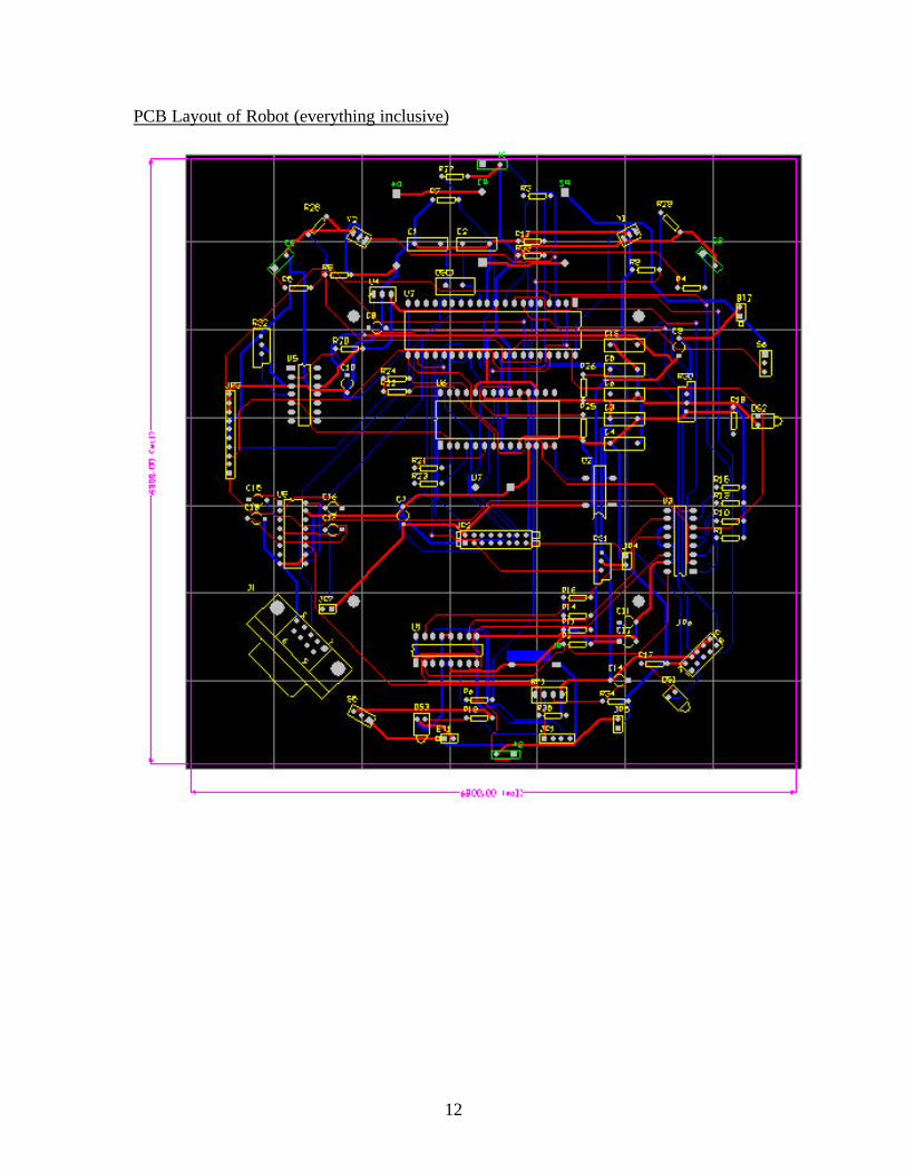
All components were put on a Protel-designed PCB. Thus the robot just consisted of oneboard—minimizing wires. This schematic of this board gives a more informativedescription of how these components were connected. The schematic is located in theAppendix.
Mobile Platform
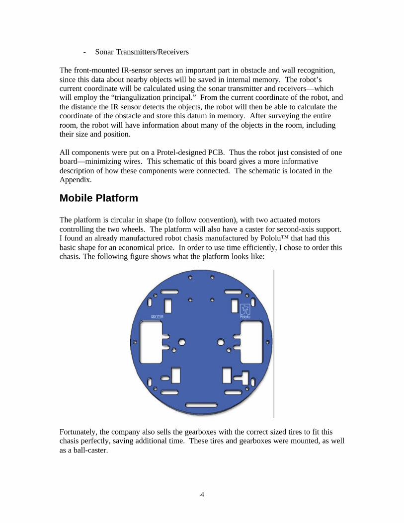
The platform is circular in shape (to follow convention), with two actuated motorscontrolling the two wheels. The platform will also have a caster for second-axis support.I found an already manufactured robot chasis manufactured by Pololu™ that had thisbasic shape for an economical price. In order to use time efficiently, I chose to order thischasis. The following figure shows what the platform looks like:
Fortunately, the company also sells the gearboxes with the correct sized tires to fit thischasis perfectly, saving additional time. These tires and gearboxes were mounted, as wellas a ball-caster.

5
Actuation
Robot movement is done by a twin-motor gearbox, which consists of two separatedrivetrains for each motor, thus each motor is independent allowing the robot to turn inplace, etc. The motors are rated for 3 VDC, but can typically be operated at up to 6VDC.
To control the motors, a Texas Instruments™ SN754410NE dual H-bridge was used,opto-iso-connected to timer 0’s PWM port, timer 2’s PWM port, and two general purposeI/O pins (for direction selection).
Sensors
The following sensors were be used:
Sensor Company/Model Location PurposeIR Proximity Sharp GP2D12 Front Obstacle/Wall
DetectionBump Switches Various Surrounding Avoid damaging
collisionSonar TX/RX Generic 3 Locations Positioning
IR Proximity
The Sharp GP2D12 was the sensor was choice because of its cost and performance. It isconnected to one of the ADC pins to monitor distances of objects ahead. The code thatinterfaces this in the Appendix. These served the purpose quite well, and were able todetect objects easily from about a few feet away.
Bump Switches
The bump switches serve as an added obstacle detection, if the IR proximity sensor failsto detect some objects. There are four mini lever-type switches that were found at asurplus store, each connected (using pull-up resistors) to two of the port pins on the
6
microcontroller. When either of these pins goes low, an interrupt is triggered to respondin an appropriate manner (in this case, move backwards and turn left) for now.
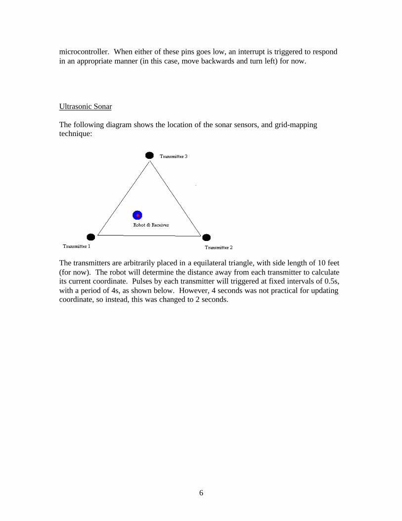
Ultrasonic Sonar
The following diagram shows the location of the sonar sensors, and grid-mappingtechnique:
The transmitters are arbitrarily placed in a equilateral triangle, with side length of 10 feet(for now). The robot will determine the distance away from each transmitter to calculateits current coordinate. Pulses by each transmitter will triggered at fixed intervals of 0.5s,with a period of 4s, as shown below. However, 4 seconds was not practical for updatingcoordinate, so instead, this was changed to 2 seconds.

7
The receiver (robot) determines the time difference between each of the pulses tocompute coordinate. The exact equations can be found in the Appendix.
The transmitters are generic (non-brand Taiwan manufactured) ultrasonic transducerswith a frequency of 40kHz and a bandwidth of 1kHz. The pulse generation of thesetransducers are done by an Atmel™ AT90S2313—where a PWM port was used for 40kHz signal generation. A tri-state driver/buffer was used to control when each transducerwould receiver the 40 kHz pulse. This timing was done by the AT90S2313, and pulsedquite precisely. The driver was connected to the common ground, and powered by a 9Vbattery. The AT90S2313 was powered via a simple 5V regulator connected to the 9Vbattery. The code for the transmitting sonar pulse generation is located in the Appedix.
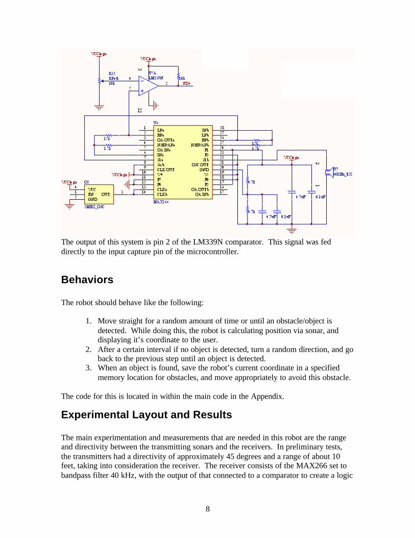
The hardware schematic for interfacing the receiving sonar was borrowed from theMIL/IMDL website, and worked very well. The schematic is shown below:
8
The output of this system is pin 2 of the LM339N comparator. This signal was feddirectly to the input capture pin of the microcontroller.
Behaviors
The robot should behave like the following:
1. Move straight for a random amount of time or until an obstacle/object isdetected. While doing this, the robot is calculating position via sonar, anddisplaying it’s coordinate to the user.
2. After a certain interval if no object is detected, turn a random direction, and goback to the previous step until an object is detected.
3. When an object is found, save the robot’s current coordinate in a specifiedmemory location for obstacles, and move appropriately to avoid this obstacle.
The code for this is located in within the main code in the Appendix.
Experimental Layout and Results
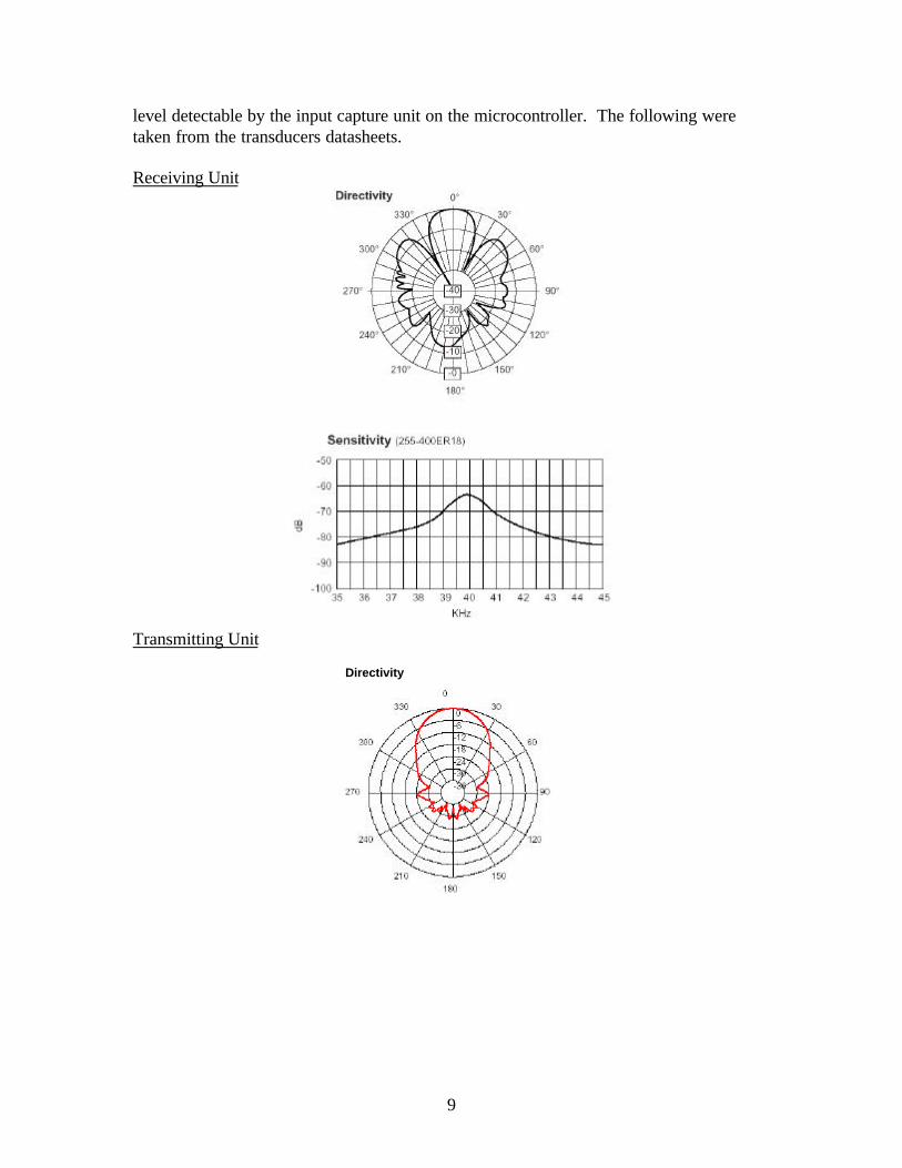
The main experimentation and measurements that are needed in this robot are the rangeand directivity between the transmitting sonars and the receivers. In preliminary tests,the transmitters had a directivity of approximately 45 degrees and a range of about 10feet, taking into consideration the receiver. The receiver consists of the MAX266 set tobandpass filter 40 kHz, with the output of that connected to a comparator to create a logic
9
level detectable by the input capture unit on the microcontroller. The following weretaken from the transducers datasheets.
Receiving Unit
Transmitting Unit
Directivity
10
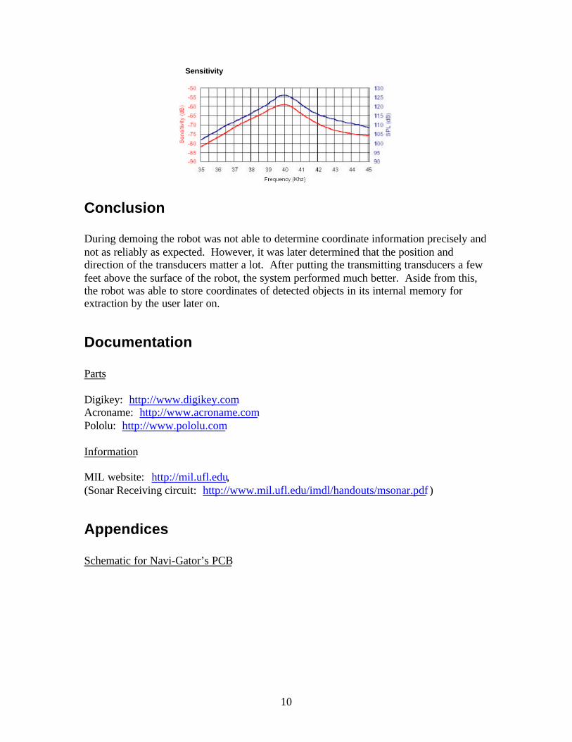
Sensitivity
Conclusion
During demoing the robot was not able to determine coordinate information precisely andnot as reliably as expected. However, it was later determined that the position anddirection of the transducers matter a lot. After putting the transmitting transducers a fewfeet above the surface of the robot, the system performed much better. Aside from this,the robot was able to store coordinates of detected objects in its internal memory forextraction by the user later on.
Documentation
Parts
Digikey: http://www.digikey.comAcroname: http://www.acroname.comPololu: http://www.pololu.com
Information
MIL website: http://mil.ufl.edu,(Sonar Receiving circuit: http://www.mil.ufl.edu/imdl/handouts/msonar.pdf )
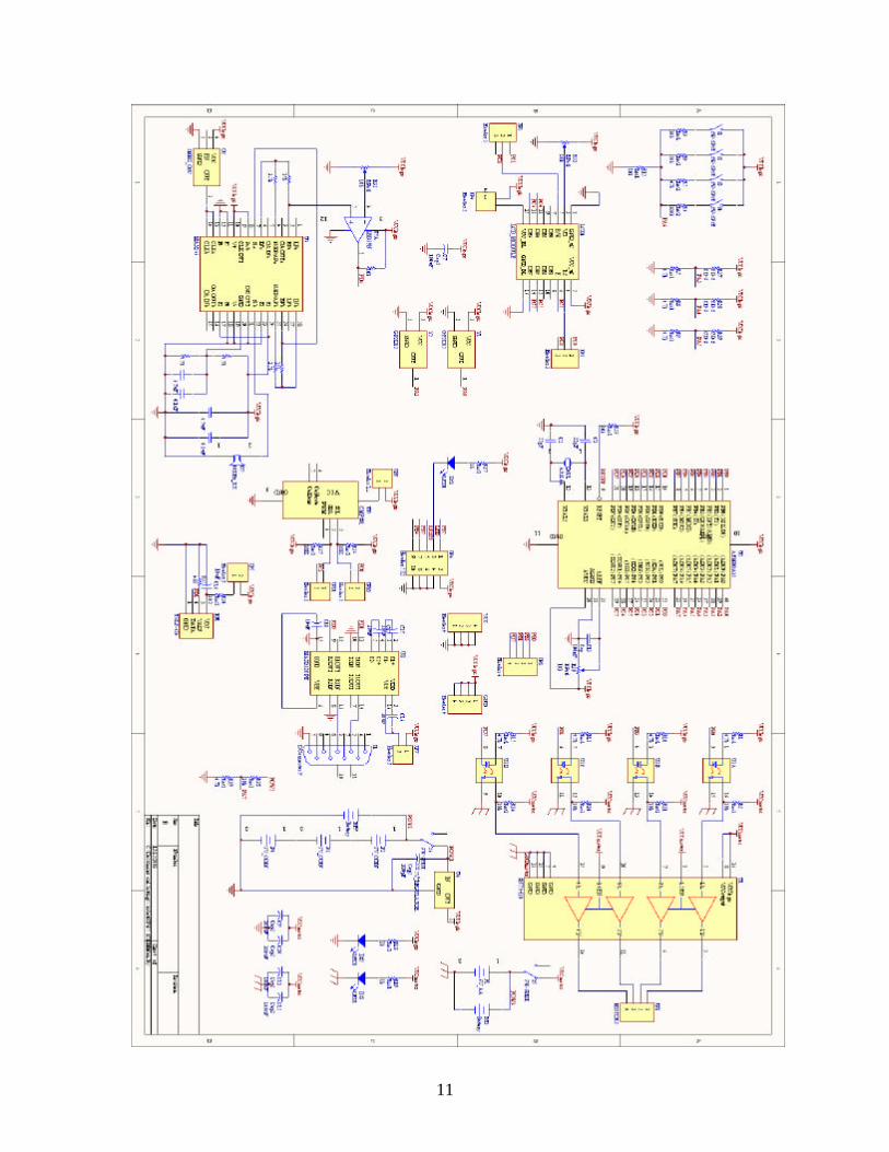
Appendices
Schematic for Navi-Gator’s PCB
11
12
PCB Layout of Robot (everything inclusive)

13
Mathcad Script for Determination and Testing of Positioning Formulas
The following shows formulas for calculation, and tests a data point to see if it comes upwith the correct coordinate. The interactive script was tested for several points, and itcame out exactly—this just shows one test point being tested.
Formulas
dist x1 y1, x2, y2,( ) x1 x2−( )2
y1 y2−( )2+:=
sound_speed 1140:=f / s at 25 degrees Celsius
time d( )d
sound_speed:=
dist_time t( ) t sound_speed⋅:=
temp1 b c,( ) b4
2 b3⋅ c⋅− b
2c2
200−( )⋅+ 200 b⋅ c⋅+ 100 c2
100−( )⋅− c2
100−( )⋅:=
temp2 b c,( ) 40 b2
b c⋅− c2+ 75−( )⋅:=
x b c,( )3− temp1 b c,( )⋅ c⋅ 2 b
3⋅ c⋅+ b2
3 c2⋅ 200−( )⋅− b c⋅ c
2300−( )⋅+ 250 c
260−( )⋅+
temp2 b c,( ):=
y b c,( ) 2 b⋅ c−( )temp1 b c,( )−
temp2 b c,( )⋅
b2
b c⋅− 50−( ) c2
100−( )⋅ 3⋅temp2 b c,( )
−:=
tx_delay 0.5:=trans1_x 0:=trans1_y 0:=trans2_x 5:=trans2_y 8.66:=trans3_x 10:=trans3_y 0:=robot_x 5:=robot_y 6:=trans1_time time dist trans1_x trans1_y, robot_x, robot_y,( )( ):=trans2_time time dist trans2_x trans2_y, robot_x, robot_y,( )( ):=trans3_time time dist trans3_x trans3_y, robot_x, robot_y,( )( ):=timer_count_1 trans1_time:=timer_count_2 trans2_time tx_delay+:=timer_count_3 trans3_time 2 tx_delay⋅+:=
What the robot knows1. Coordinates of ALL 3 transmitters
r_trans1_x 0:=r_trans1_y 0:=r_trans2_x 5:=r_trans2_y 8.66:=r_trans3_x 10:=r_trans3_y 0:=2. The delay between each transmitters pulse sent
r_tx_delay 0.5:=3. Time differences between each of the detected pulses
r_time_12 timer_count_2 timer_count_1−:=r_time_13 timer_count_3 timer_count_1−:=
14
Calculation of Position1. Calculate differential distances
r_dist_12 dist_time r_time_12 r_tx_delay−( ):=r_dist_13 dist_time r_time_13 2 r_tx_delay⋅−( ):=2. Calculate Position
x r_dist_12 r_dist_13,( ) 5=y r_dist_12 r_dist_13,( ) 6=
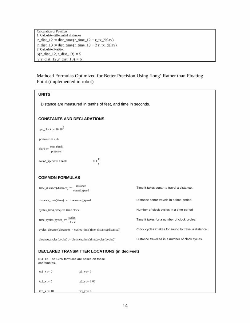
Mathcad Formulas Optimized for Better Precision Using ‘long’ Rather than FloatingPoint (implemented in robot)
Distance travelled in a number of clock cycles. distance_cycles cycles( ) distance_time time_cycles cycles( )( ):=
Clock cycles it takes for sound to travel a distance. cycles_distance distance( ) cycles_time time_distance distance( )( ):=
Time it takes for a number of clock cycles. time_cycles cycles( )cycles
clock:=
Number of clock cycles in a time period cycles_time time( ) time clock⋅:=
Distance sonar travels in a time period. distance_time time( ) time sound_speed⋅:=
Time it takes sonar to travel a distance.time_distance distance( )distance
sound_speed:=
COMMON FORMULAS
0.1ft
ssound_speed 11400:=
clockcpu_clock
prescaler:=
prescaler 256:=
cpu_clock 16 106⋅:=
CONSTANTS AND DECLARATIONS
Distance are measured in tenths of feet, and time in seconds.
UNITS
DECLARED TRANSMITTER LOCATIONS (in deciFeet)
NOTE: The GPS formulas are based on these coordinates.
tx1_x 0:= tx1_y 0:=
tx2_x 5:= tx2_y 8.66:=
tx3_x 10:= tx3_y 0:=
15
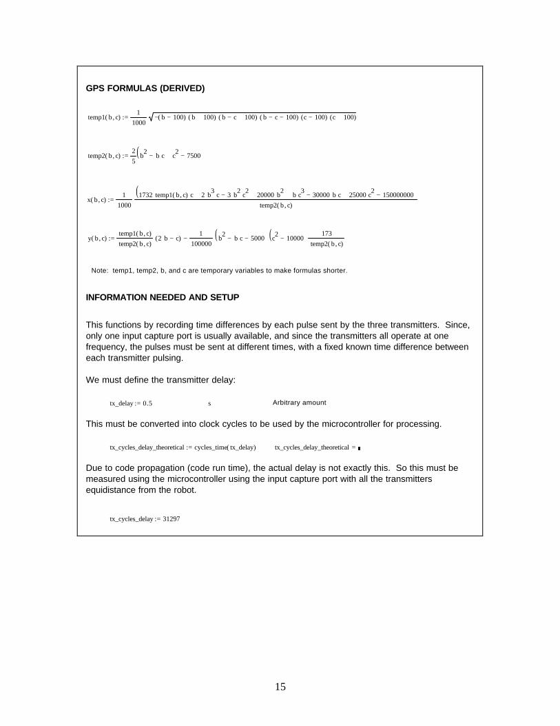
GPS FORMULAS (DERIVED)
temp1 b c,( )1
1000b 100−( )− b 100+( )⋅ b c− 100+( )⋅ b c− 100−( )⋅ c 100−( )⋅ c 100+( )⋅⋅:=
temp2 b c,( )2
5b2
b c⋅− c2
7500−+( ):=
x b c,( )1
1000
1732 temp1 b c,( )⋅ c⋅ 2 b3⋅ c⋅ 3 b
2⋅ c2⋅−+ 20000 b
2⋅+ b c3⋅ 30000 b⋅ c⋅−+ 25000 c
2⋅ 150000000−+( )temp2 b c,( )
⋅:=
y b c,( )temp1 b c,( )
temp2 b c,( )2 b⋅ c−( )⋅
1
100000b2
b c⋅− 5000−( )⋅ c2
10000−( )⋅173
temp2 b c,( )⋅−:=
Note: temp1, temp2, b, and c are temporary variables to make formulas shorter.
INFORMATION NEEDED AND SETUP
This functions by recording time differences by each pulse sent by the three transmitters. Since, only one input capture port is usually available, and since the transmitters all operate at one frequency, the pulses must be sent at different times, with a fixed known time difference between each transmitter pulsing.
We must define the transmitter delay:
tx_delay 0.5:= s Arbitrary amount
This must be converted into clock cycles to be used by the microcontroller for processing.
tx_cycles_delay_theoretical cycles_time tx_delay( ):= tx_cycles_delay_theoretical =
Due to code propagation (code run time), the actual delay is not exactly this. So this must be measured using the microcontroller using the input capture port with all the transmitters equidistance from the robot.
tx_cycles_delay 31297:=
16
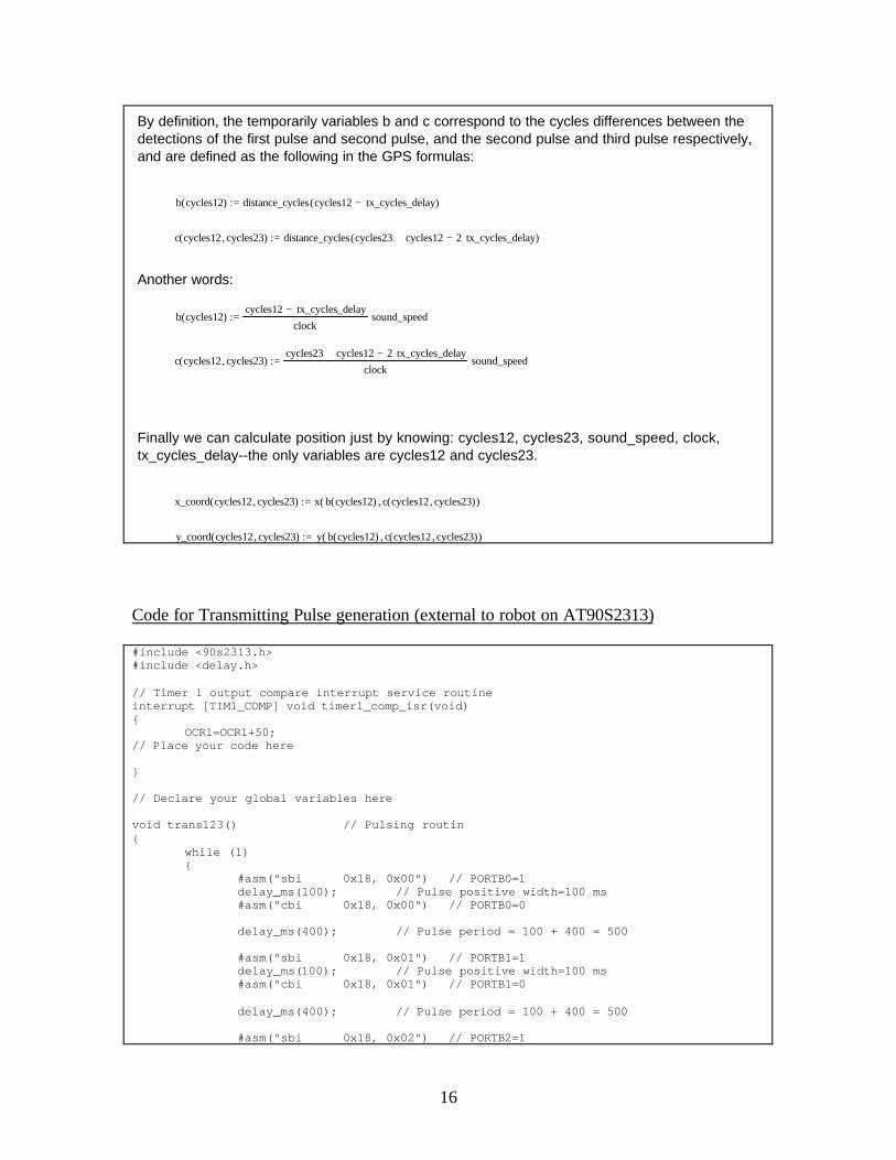
By definition, the temporarily variables b and c correspond to the cycles differences between the detections of the first pulse and second pulse, and the second pulse and third pulse respectively, and are defined as the following in the GPS formulas:
b cycles12( ) distance_cycles cycles12 tx_cycles_delay−( ):=
c cycles12 cycles23,( ) distance_cycles cycles23 cycles12+ 2 tx_cycles_delay⋅−( ):=
Another words:
b cycles12( )cycles12 tx_cycles_delay−
clocksound_speed⋅:=
c cycles12 cycles23,( )cycles23 cycles12+ 2 tx_cycles_delay⋅−
clocksound_speed⋅:=
Finally we can calculate position just by knowing: cycles12, cycles23, sound_speed, clock, tx_cycles_delay--the only variables are cycles12 and cycles23.
x_coord cycles12 cycles23,( ) x b cycles12( ) c cycles12 cycles23,( ),( ):=
y_coord cycles12 cycles23,( ) y b cycles12( ) c cycles12 cycles23,( ),( ):=
Code for Transmitting Pulse generation (external to robot on AT90S2313)
#include <90s2313.h>#include <delay.h>
// Timer 1 output compare interrupt service routineinterrupt [TIM1_COMP] void timer1_comp_isr(void){
OCR1=OCR1+50;// Place your code here
}
// Declare your global variables here
void trans123() // Pulsing routin{
while (1){
#asm("sbi 0x18, 0x00") // PORTB0=1 delay_ms(100); // Pulse positive width=100 ms #asm("cbi 0x18, 0x00") // PORTB0=0
delay_ms(400); // Pulse period = 100 + 400 = 500
#asm("sbi 0x18, 0x01") // PORTB1=1 delay_ms(100); // Pulse positive width=100 ms #asm("cbi 0x18, 0x01") // PORTB1=0
delay_ms(400); // Pulse period = 100 + 400 = 500
#asm("sbi 0x18, 0x02") // PORTB2=1
17
delay_ms(100); // Pulse positive width=100 ms #asm("cbi 0x18, 0x02") // PORTB2=0
delay_ms(900); // Pulse period = 100 + 400 = 500 }}
void trans111() // Debugging, testing routines{
while (1){
#asm("sbi 0x18, 0x01") // PORTB1=1 delay_ms(100); // Pulse positive width=100 ms #asm("cbi 0x18, 0x01") // PORTB1=0
delay_ms(400); // Pulse period = 100 + 400 = 500
#asm("sbi 0x18, 0x01") // PORTB1=1 delay_ms(100); // Pulse positive width=100 ms #asm("cbi 0x18, 0x01") // PORTB1=0
delay_ms(400); // Pulse period = 100 + 400 = 500
#asm("sbi 0x18, 0x01") // PORTB1=1 delay_ms(100); // Pulse positive width=100 ms #asm("cbi 0x18, 0x01") // PORTB1=0
delay_ms(900); // Pulse period = 100 + 400 = 500 }}
void trans1() // Debugging, testing routines{
while (1){
#asm("sbi 0x18, 0x01") // PORTB1=1 delay_ms(100); // Pulse positive width=100 ms #asm("cbi 0x18, 0x01") // PORTB1=0
delay_ms(400); // Pulse period = 100 + 400 = 500 }}
void main(void){// Declare your local variables here
// Input/Output Ports initialization// Port B initialization// Func0=Out Func1=Out Func2=Out Func3=Out Func4=In Func5=In Func6=In Func7=In// State0=0 State1=0 State2=0 State3=0 State4=T State5=T State6=T State7=TPORTB=0x00;DDRB=0x0F;
// Port D initialization// Func0=In Func1=In Func2=In Func3=In Func4=In Func5=In Func6=In// State0=T State1=T State2=T State3=T State4=T State5=T State6=TPORTD=0x00;DDRD=0x00;
// Timer/Counter 0 initialization// Clock source: System Clock// Clock value: Timer 0 StoppedTCCR0=0x00;TCNT0=0x00;
// Timer/Counter 1 initialization

18
// Clock source: System Clock// Clock value: 4000.000 kHz// Mode: Normal top=FFFFh// OC1 output: Toggle// Noise Canceler: Off// Input Capture on Falling EdgeTCCR1A=0x40;TCCR1B=0x09;TCNT1H=0x00;TCNT1L=0x00;OCR1H=0x00;OCR1L=49;
// External Interrupt(s) initialization// INT0: Off// INT1: OffGIMSK=0x00;MCUCR=0x00;
// Timer(s)/Counter(s) Interrupt(s) initializationTIMSK=0x00;
// Analog Comparator initialization// Analog Comparator: Off// Analog Comparator Input Capture by Timer/Counter 1: Off// Analog Comparator Output: OffACSR=0x80;
// Global enable interrupts#asm("sei")
while (1) {
trans123(); // Start pulsing };}
Code for robot’s behaviors
#include <mega16.h>
// Alphanumeric LCD Module functions#asm .equ __lcd_port=0x15#endasm#include <lcd.h>#include <delay.h>#include <stdlib.h>#include <math.h>
#define ADC_VREF_TYPE 0x00// Read the AD conversion resultunsigned int read_adc(unsigned char adc_input){ADMUX=adc_input|ADC_VREF_TYPE;// Start the AD conversionADCSRA|=0x40;// Wait for the AD conversion to completewhile ((ADCSRA & 0x10)==0);ADCSRA|=0x10;return ADCW;}
const unsigned int normalspeed=50;const unsigned int irnear=300;const unsigned int turntime=2000;const unsigned int reversetime=2000;const signed long tx_delay=31297, clock_speed=62500, sound_speed=11400;
19
unsigned char ovcounter; // counter for timer overflowunsigned long sens1, sens2, cycles_12, cycles_23; // sens1=time when TX1 pulsed, andsens2=TX2, cycles12,23 are pulse differencessigned long xpos, ypos, tempv1, tempv2, b2,b3,c2,c3; // Coordinate and temporaryvariablesunsigned long pulse_clocks;signed long bbv, ccv; // temp varschar mystr[12];char transn; // Can be 1, 2, 3.. Indicates transducer it is currently looking for.unsigned int vals12[40]; // Array for storage of detected objects, xunsigned int vals23[40]; // y coord Arraychar i12; // Iterator for arrays
signed long bb(signed long cycles12) // Temporaryvariable/function for positioning calculation{
return (( cycles12 - tx_delay )*sound_speed/clock_speed );}
signed long cc(signed long cycles12, signed long cycles23) // Temporaryvariable/function for positioning calculation{
return (cycles23 + cycles12 - 2*tx_delay)*sound_speed/clock_speed;}
signed int ipow(signed int base, unsigned int exp) // Outputs base^exp{
if (exp==1) return base;if (exp==0) return 1;
return (base*ipow(base,exp-1));}
signed long lpow(signed long base, unsigned int exp) // Outputs base^exp{
if (exp==1) return base;if (exp==0) return 1;
return (base*lpow(base,exp-1));}
signed long temp1(signed long b, signed long c) // Temporaryvariable/function for positioning calculation{
return (signed long)lsqrt((unsigned long) ((-1*(b-100)*(b+100)*(b-c+100)*(b-c-100)/1000000)*(c-100)*(c+100)) );}
signed long temp2(signed long b, signed long c) // Temporaryvariable/function for positioning calculation{
return ( 2*(b2-b*c+c2-7500)/5 );}
signed long xcoord(signed long b, signed long c) //Calculatescoordinate{
return ( ( (1732*tempv1*c + 2*b3*c2 - 3*b2*c2 + b*c3)/1000 + 20*b2 - 30*b*c +25*c2 - 150000 )/tempv2 );}
/*signed long xcoord(signed long b, signed c){
return ( ( 1732*tempv1*c + 2*b3*c2 - 3*b2*c2 + b*c3 + 20000*b2 - 30000*b*c +25000*c2 - 150000000 )/(1000*tempv2) );}*/
signed long ycoord(signed long b, signed long c) // Y coordinate
20
{return ( ( 20*tempv1*b - 10*tempv1*c - 865000 + 173*b2 - 173*b*c + (173*b*c3 -
173*b2*c2 + 865000*c2)/10000 ) / (10*tempv2) );}
void initcal() // Sets up temporaryvariables for calculation{
bbv=bb(cycles_12);ccv=cc(cycles_12,cycles_23);
b2=lpow(bbv,2); b3=lpow(bbv,3); c2=lpow(ccv,2); c3=lpow(ccv,3); tempv1=temp1(bbv,ccv); tempv2=temp2(bbv,ccv);}
void display(char flash *str){
lcd_clear();lcd_putsf(str);delay_ms(20);
}
void displayxy(unsigned char x, unsigned char y, char flash *str){
lcd_gotoxy(x,y);lcd_putsf(str);delay_ms(20);
}
void displayxys(unsigned char x, unsigned char y, char *str){
lcd_gotoxy(x,y);lcd_puts(str);delay_ms(20);
}
void displays(char *str){
lcd_clear();lcd_puts(str);delay_ms(20);
}
void calcoord() // Main function which calls otherfunctions to calc coord.{
initcal();xpos=xcoord(bbv,ccv);
ltoa(xpos,mystr);displayxys(0,0,mystr);
ypos=ycoord(bbv,ccv);
ltoa(ypos,mystr);displayxys(0,1,mystr);
//ypos}
// Timer 1 overflow interrupt service routineinterrupt [TIM1_OVF] void timer1_ovf_isr(void){
ovcounter++;
21
}
// Timer 1 input capture interrupt service routineinterrupt [TIM1_CAPT] void timer1_capt_isr(void) // ISR for detecting pulsesfrom TX.{ #asm("cli")
sens2=(unsigned long)ICR1L + (unsigned long)ICR1H * 0x100;pulse_clocks=(unsigned long)sens2 - (unsigned long)sens1 + ((unsigned
long)ovcounter) * 0x10000;if ((pulse_clocks > 22000)) //Used to be 5500{ // Valid Pulse
if (pulse_clocks > 100000) // used to be 25000{
displayxy(7,1,"L");}
else {
displayxy(7,1," ");
if (pulse_clocks > 40000) //This block determines which transducer tolook for next. //Used to be 10k
{ transn=2; // Found trans 1, now next time look for 2
}else{
if (transn==2) // Found trans 2, save difference { cycles_12=pulse_clocks; transn=3;// ltoa(cycles_12,mystr);// displayxys(0,0,mystr);
} else { if (transn==3) // Found trans 3, save difference anddisplay coordinate { cycles_23=pulse_clocks; transn=1;// ltoa(cycles_23,mystr);// displayxys(0,1,mystr);
calcoord();
} }
} }
sens1=sens2;ovcounter=0;
delay_ms(150);}
#asm("sei")}
unsigned int randdir() // Random direction generator{
return (((rand()%10)/5));}
22
//Direction 0 is forward, 1 is backwards.. Input speed from 0-255void leftmotor(unsigned int direction, unsigned int speed){
speed=speed+speed/4;
if (direction==0){
PORTB=PORTB | 0x01; //Turn PB0 on (specifies polarity of motor...speed=255-speed; // Adjust for reverse speed (polarity reversal of
PB0)}else
PORTB=PORTB & 0x02; //Turn PB0 off (and leave PB1 alone);
OCR0=speed;}
void rightmotor(unsigned int direction, unsigned int speed){
speed=speed;
if (direction==1){
PORTB=PORTB | 0x02; //Turn PB1 on (specifies polarity of motor...speed=255-speed; // Adjust for reverse speed (polarity reversal of
PB1)}else
PORTB=PORTB & 0x01; //Turn PB1 off (and leave PB0 alone);
OCR2=speed;}
unsigned int rightIR() // Outputs reading of right IR{
return read_adc(0);}
unsigned int leftIR(){
return read_adc(1);}
// The following functions do the specified task for a length of t milliseconds
void stopt(unsigned int t) { rightmotor(0,0); leftmotor(0,0); delay_ms(t);}
void turnleftt(unsigned int t){
rightmotor(0,normalspeed/2);leftmotor(1,normalspeed/2);delay_ms(t);stopt(5);
}
void turnrightt(unsigned int t){
rightmotor(1,normalspeed/2);leftmotor(0,normalspeed/2);delay_ms(t);stopt(5);
}
23
void forwardt(unsigned int t){
rightmotor(0,normalspeed);leftmotor(0,normalspeed);delay_ms(t);stopt(5);
}
void reverset(unsigned int t){
rightmotor(1,normalspeed);leftmotor(1,normalspeed);delay_ms(t);stopt(5);
}
// These do the specified movements continuously until stop() is issued
void stop(){ rightmotor(0,0); leftmotor(0,0);}
void turnleft(){
rightmotor(0,normalspeed/2);leftmotor(1,normalspeed/2);
}
void turnright(){
rightmotor(1,normalspeed/2);leftmotor(0,normalspeed/2);
}
void forward(){
rightmotor(0,normalspeed);leftmotor(0,normalspeed);
}
void reverse(){
rightmotor(1,normalspeed);leftmotor(1,normalspeed);
}
unsigned int rnear(){
if (rightIR()>irnear)return 1;
elsereturn 0;
}
unsigned int lnear(){
if (leftIR()>irnear)return 1;
elsereturn 0;
}
void avoid() // Main obstacle avoidance/detection function{ displayxy(7,0,"F");
forward();

24
while((rnear()==0) && (lnear()==0)) { delay_ms(100); //Arbit. 100ms delay };
displayxy(7,0,"O");
i12=i12%10;vals12[i12]=cycles_12;vals23[i12++]=cycles_23;
delay_ms(100);reverset(reversetime/2); //reverse for 1s if both indicate an
object
delay_ms(1000);
delay_ms(3000);
reverset(reversetime/2);
if (rnear()==1 && lnear()==1) { if (randdir()==0) { turnrightt(turntime);
}else{
turnleftt(turntime);}
} else if (rnear()==1) {// displayxy(5,0,"OBJ");
turnleftt(turntime); } else {
// displayxy(5,0,"OBJ"); turnrightt(turntime); }
}
// Declare your global variables here
void main(void){// Declare your local variables here
// Input/Output Ports initialization// Port A initialization// Func0=In Func1=In Func2=In Func3=In Func4=In Func5=In Func6=In Func7=In// State0=T State1=T State2=T State3=T State4=T State5=T State6=T State7=TPORTA=0x00;DDRA=0x00;
// Port B initialization// Func0=Out Func1=Out Func2=In Func3=Out Func4=In Func5=In Func6=In Func7=In// State0=0 State1=0 State2=T State3=0 State4=T State5=T State6=T State7=TPORTB=0x00;DDRB=0x0B;
// Port C initialization// Func0=In Func1=In Func2=In Func3=In Func4=In Func5=In Func6=In Func7=In// State0=T State1=T State2=T State3=T State4=T State5=T State6=T State7=T
25
PORTC=0x00;DDRC=0x00;
// Port D initialization// Func0=In Func1=In Func2=In Func3=In Func4=In Func5=In Func6=In Func7=Out// State0=T State1=T State2=T State3=T State4=T State5=T State6=T State7=0PORTD=0x00;DDRD=0x80;
// Timer/Counter 0 initialization// Clock source: System Clock// Clock value: 15.625 kHz// Mode: Fast PWM top=FFh// OC0 output: Non-Inverted PWMTCCR0=0x6D;TCNT0=0x00;OCR0=0x00;
// Timer/Counter 1 initialization// Clock source: System Clock// Clock value: 16000.000 kHz// Mode: Normal top=FFFFh// OC1A output: Discon.// OC1B output: Discon.// Noise Canceler: On// Input Capture on Rising EdgeTCCR1A=0x00;TCCR1B=0xC4; //bit 7 is noise cancellor bit (on=enable)
//bit 2..0: 101: prescal=1024, 001: prescal=1 (page 111), 100=256TCNT1H=0x00;TCNT1L=0x00;OCR1AH=0x00;OCR1AL=0x00;OCR1BH=0x00;OCR1BL=0x00;
// Timer/Counter 2 initialization// Clock source: System Clock// Clock value: 15.625 kHz// Mode: Fast PWM top=FFh// OC2 output: Non-Inverted PWMTCCR2=0x6F;ASSR=0x00;TCNT2=0x00;OCR2=0x00;
// External Interrupt(s) initialization// INT0: Off// INT1: Off// INT2: OffGICR=0x00;MCUCR=0x00;MCUCSR=0x00;
// Timer(s)/Counter(s) Interrupt(s) initializationTIMSK=0x24;
// Analog Comparator initialization// Analog Comparator: Off// Analog Comparator Input Capture by Timer/Counter 1: Off// Analog Comparator Output: OffACSR=0x80;SFIOR=0x00;
// ADC initialization// ADC Clock frequency: 8000.000 kHz// ADC Voltage Reference: AREF pin// ADC High Speed Mode: Off// ADC Auto Trigger Source: NoneADMUX=ADC_VREF_TYPE;ADCSRA=0x81;
26
SFIOR=0x00;
// LCD module initializationlcd_init(8);
srand(19);
//stopt(4000); //Pause for 4 seconds for user to get away
display("GO!");delay_ms(2000);
transn=1; // Set guess to transmitter 1
i12=0;
#asm("sei") // Setup all interrupts
while (1) {
avoid(); // Run obstacle avoidance, rest is done by interrupts
};}