naval postgraduate school monterey, · pdf filenaval postgraduate school monterey, california...
TRANSCRIPT

NAVAL POSTGRADUATE SCHOOLMonterey, California
Ln~
00S-DTIC_
-S ELECTENOV 2 7 1992DA THESIS
IMPROVING SECURITY IN THEFIBER DISTRIBUTED DATA INTERFACE (FDDI)
PROTOCOL
by
Benjamin Edward Jones
September 1992
Thesis Advisor: G.M. LundCo-Advisor: Roger Stemp
Approved for public release; distribution is unlimited.
92-30276

UNCLASSIFIEDSECURITY CLASSFICATION OF THIS PAGE
iii REPORT DOCUMENTATION PAGE
lia REPORT SECURITY CLASSIFIGATION UNCLASSIFIED lb. RESTRICTIVE MARKINGS
2f SECURITY CLASSIFICATION AUTHORITY 3. DIT•SIBUTION/AVAILABILITY OF REPORT
2b. DECLASSIF1CATIONWDOWNGRADING SCHEDULE Approved for public release;"distribution is unlimited
4. PERFORMING ORGANIZATION REPORT NUMBER(S) 5. MONITORING ORGANIZATION REPORT NUMBER(S)
ft NAME OF gERFORMWG ORGANIZATION 6b. OFFESYMBOL 7a. NAME OF MONITORING ORGANIZATIONLOputer •cience Dept. =(i !ybi•)B Naval Postgraduate School
Naval Postgraduate School CS/Ln
6c. ADDRESS (City, State, and ZIP Code) 7b. ADDRESS (City, State, and ZIP Code)
Monterey, CA 93943-5000 Monterey, CA 93943-5000
NAM FFUNDINGSPONRING . OFFICE SYMBOL 9. PROCUREMENT INSTRUMENT IDENTIFICATION NUMBERORGNIZATION (if appficable)
8c. ADDRESS (City, State, and ZIP Code) 10. SOURCE OF FUNDING NUMBERSPROGRAM PRJECT ITASK WORK UNITELEMENT NO. NO. NO. ACCESSION NO.
11. TITLE (include Secwity C/asificadon)
IMPROVING SECURITY IN THE FDDI PROTOCOL2. PERWAL. AUSHy.."(5)ones, B~enjamin E3.
TYPý EP.ORT 131). TIME COVERED 14. DATE OF REPORT (Year, Month, Day) 15. PAGE COUNT
aiter s"N sis FROM 7/90 TO: September 1992 7316. SUPPLEMENTARY NT o &viWSexpressed in this thesis are those ot the author and do not reflect the officialpolicy or position of the Department of Defense or the United States Government
17. COSATI CODES 18. SUBJECT TERMS (Continue on reverse if necessary and identify by block number)
FIELD GROUP SUB-GROUP
19. ABSTRACT (Coninue on reverse if necessaty and idenify by block number)The arrival of high speed packet switched fiber optic LANs has allowed local area design architectures to be used for larger
metropolitan area network (MAN) implementations. The current LAN security mechanisms used in larger and faster fiber opticLANs and MANs are often inappropriate or unacceptable for use with emerging applications.
The protocol of the Fiber Distributed Data Interface (FDDI) standard provides a natural means for message integrity andavailability verification. However, privacy in FDDI is facilitated at higher layers through a generic LAN standard. This thesisproposes a modification to the FDDI protocol implemented at the medium access control (MAC) sublayer, which integrates aconfidentiality mechanism for data transfer. The modification provides a simple comprehensive security package to meet thehigh performance needs of current and emerging applications.
In the proposed modification, the inherent properties of the ring are exploited using a unique Central Key Translator todistribute initial session keys. A symmetric bit stream cipher based on modulo2 addition is used for encryption/decryption bythe transmitting and receiving stations. Part of the plaintext from transmitted message frames is used as feedback to generatenew session keys.
20. DISTRIBUTION/AVAILABILITY OF ABSTRACT 21. ABSTRACT SECURITY CLASSIFICATION[] UNCLASSIFIEDOINLIMITED [] SAME AS RPT. Q] DTIC USERS UNCLASSIFIEDVrWnE-, A RESPONSIBLE INDIVIDUAL 2 Aa Coe l CE SYMBOL.
All other editions are obsolete SECURITY CLASSIFICATION OF THIS PAGE
UNCLASSIFIED
Approved for public release; distribution is unlimited
IMPROVING SECURITY IN THE FDDI PROTOCOL
byBenjamin E. Jones
Lieutenant, United States NavyB.S., Virginia Polytechnic Institute 1983
Submitted in partial fulfillment of therequirements for the degree of
MASTER OF COMPUTER SCIENCE
from the
NAVAL POSTGRADUATE SCHOOLSeptember 1992
Author:
" /Benjamiun E. Jo•
Approved By: Zu'
Roger Stemff, Co-Advisor
r,• Rb~rt k Qhee, Chairman,SDepartment of Computer Science
ABSTRACT
The arrival of high speed packet switched fiber optic LANs has allowed local area design
architectures to be used for larger metropolitan area network (MAN) implementations. The current
LAN security mechanisms used in larger and faster fiber optic LANs and MANs are often
inappropriate or unacceptable for use with emerging applications.
The protocol of the Fiber Distributed Data Interface (FDDI) standard provides a natural
means for message integrity and availability verification. However, privacy in FDDI is facilitated
at higher layers through a generic LAN standard. This thesis proposes a modification to the FDDI
protocol implemented at the medium access control (MAC) sublayer, which integrates a
confidentiality mechanism for data transfer. The modification provides a simple comprehensive
security package to meet the high performance needs of current and emerging applications.
In the proposed modification, the inherent properties of the ring are exploited using a unique
Central Key Translator to distribute initial session keys. A symmetric bit stream cipher based on
modulo2 addition is used for encryption/decryption by the transmitting and receiving stations. Part
of the plaintext from transmitted message frames is used as feedback to generate new session keys.
W
TABLE OF CONTENTS
I. INTRODUCTION ...................................................................................................... 1A. M OTIVATION ................................................................................................. 1
1. Technology Trends ................................................................................. 12. Recent Events .................................................................................... 13. M ilitary Applications ......................................................................... 24. Focus and Goals ................................................................................. 4
B. SCOPE ....................................................................................................... 51. Security Elements .............................................................................. 52. Security Threats ................................................................................ 6
C. ORGANIZATION ...................................................................................... 7II. FIBER OPTICS, LANS AND SECURITY .......................................................... 8
A. LAN/M AN ISSUES ................................................................................... 81. LAN Issues ........................................................................................ 82. Traffic Analysis ................................................................................. 9
B. FIBER AND SECURITY .......................................................................... 101. Electromagnetic vs. Light Energy .................................................... 102. Power and Code Division ............................................................... 113. Optical Bidirectionality .................................................................. 12
C. TOKEN RING ARCHITECTURE ........................................................... 13IIM . FDDI AND SECURITY ..................................................................................... 16
A. FDDI .......................................................................................................... 161. Basic FDDI ..................................................................................... 162. FDDI-II .......................................................................................... 19
B. CONFIDENTIALITY AND FDDI .......................................................... 201. M odification Design Issues ............................................................. 202. M AC Level Implementation .......................................................... 223. Key M anagement ............................................................................ 244. IV Buffers ........................................................................................ 265. Confidential Communications ........................................................ 286. Security Procedures .......................................................................... 297. M AC M odifications ......................................................................... 338. Degraded Operation Alternatives ................................................... 35
IV. CONCLUSIONS AND RECOMENDATIONS ................................................ 37A. DISCUSSION ........................................................................................... 37B. FUTURE RESEARCH ............................................................................ 39
APPENDIX A: FDDI MEDIA ACCESS CONTROL (MAC-2) ............................... 41A. ABBREVIATIONS ................................................................................... 41B. M AC RECEIVER ALGOR ITHM ........................................................... 45C. MAC TRANSMITTER ALGORITHM ................................................... 49
APPENDIX B: DATA ENCRYPTION AND NETWORKS ...................................... 52A. OVERVIEW OF CRYPTOGRAPHY ...................................................... 52
iv
1. Stream Ciphers ...................................................................................... 542. Block Ciphers ................................................................................. 553. Key Systems .................................................................................... 56
B. DATA ENCRYPTION STANDARD (DES) ............................................ 59C. RIVEST-SHAMIR-ADELMAN (RSA) ENCRYPTION ......................... 59D. LINK VS. END TO END ENCRYPTION ............................................... 60
LIST OF REFERENCES ............................................................................................ 61BIBLIOGRAPHY ............................................................................................................. 63INITIAL DISTRIBUTION LIST ............................................................................... 65
DTIC QUALI 77 N.P-ECTIED 4
Accesion ForNTIS CRAWIDTIC TAB 0[
Unannounced 13Bj.tif.ication . .........
B Y.--- ----- .---- •-------- ----- " 'Distributicili
"Av .. '.
v

LIST OF FIGURES
Figure 1. SAFENET Interconnect .......................................................................... 3Figure 2. Interconnected Network System ............................................................. 8Figure 3. Schematic of Modified Star Coupler ......................................................... 11Figure 4. Token Ring Security Properties ........................................................... 14Figure 5. Dual Ring Adaptability ......................................................................... 15Figure 6. FDDI Frame ........................................................................................ 17Figure 7. Fiber Distributed Data Interface .......................................................... 18Figure 8. FDDI in the Wrap Mode ....................................................................... 19Figure 9. ISO Network Layers ............................................................................ 23Figure 10. Frame Check Sequence Coverage in an FDDI Frame ......................... 24Figure 11. Central Key Translator Protocol ........................................................... 26Figure 12. Station IV Buffer Management ........................................................... 28Figure 13. Modified MAC Receiver State Diagram (States Affected) ................. 34Figure 14. Modified MAC Transmitter State Diagram (States Affected) .............. 35Figure 15. MAC Receiver State Diagram ............................................................. 44Figure 16. MAC Transmitter State Diagram ......................................................... 48Figure 17. Basic Crypto System ............................................................................ 53Figure 18. Stream Cipher Variations ..................................................................... 54Figure 19. Key Server Distributing Session Keys ................................................. 57
vi
L INTRODUCTION
A. MOTIVATION
1. Technology Trends
The continuing trend toward more advanced computer communication
technologies has led to greater demands for new communication services. The use of high
speed fiber optic networks has resulted in tremendous increases in data rates. One problem
observed in computer network design is the lack of attention given to providing secure
communications. Security controls are often applied as ad hoc mechanisms based on
previous technologies or applications. In many instances a new technology may possess
intrinsic properties not present in previous systems. These undeveloped properties may
offer promising new methods for supporting secure communications. Likewise, the needs
of new applications may make the older security mechanisms inappropriate or obsolete.
Advances in computing have resulted in more sophisticated methods of
committing malicious computer network security violations. Cryptanalysis techniques
have improved dramatically as a result of advances in automated data processing. Faster
processors provide cryptanalysts with powerful tools for breaking ciphers. In addition,
higher data rates provide the crytanalyst with more ciphertext from which encryption keys
and algorithms may be discovered. The requirements and limitations associated with high
speed communication technology present a dynamic situation requiring ongoing attention.
2. Recent Events
Computer Security has always been a concern among those in the industry.
However recent events have focused more attention on the subject. In his book "The
Cuckoo's Egg" Cliff Stoll describes his encounter with of group of West German computer
hackers who successfully broke into military, government and educational computer
systems using network links to U.S. computers. [Stoll 90]In 1986 a computing system at a
secure scientific research laboratory in the U.S. was penetrated. In 1983 juveniles from

Milwaukee, Wisconsin, broke into many computer systems including Sloan-Kettering
Hospital and Security Pacific Bank. [Pfile 89] The implications of compromised national
security, invasion of financial institution records and medical facilities are enormous.
Robbers can steal more with computers than with a gun; terrorists could do more permanent
damage with a keyboard than with a bomb.[Adam 92] Consequently increasing attention is
being focused on the shortcomings of current security systems and the need for more
forethought in future system design.
3. Military Applications
a. SAFENET
The Survivable Adaptable Fiber Optic Embedded Network (SAFENET)
program is part of the Next Generation Computer Resource (NGCR) program and
represents the United States Navy's effort to meet the data transfer demands of Navy
shipboard mission critical computer systems through development of standard computer
network profiles (see Figure 1). The Navy's requirements include survivability, increased
connectivity, performance and future system expansion capabilities. There are currently
two SAFENET standards being developed. SAFENET-I is based on the 16 Mbps fiber
media version of the IEEE 802.5 token ring architecture. SAFENET-H is based on the 100
Mbps ANSI X3T9.5 fiber distributed data interface (FDDI) protocol and is intended for
Navy computer systems with high data throughput requirements. Both versions employ a
graded index, radiation resistant fiber medium, with dual counter rotating rings capable of
surviving five consecutive bypassed stations. Layers 3 through 7 of the International
Standards Organization (ISO) are the same for both SAFENET-I and SAFENET 11. System
level LANs are maintained by various ships systems such as Anti-Surface Warfare
(ASUW), Anti-Submarine Warfare (ASW), Hull, Machinery, Electrical (HM&E) etc. The
system level LANs operate to meet the specific needs of their respective systems
requirements. A backbone LAN would be used to interconnect the system LANs in order
to facilitate sharing of information between systems. The system LANs would act as
2

concentrators to reduce the I/O requirements on the backbone. The effect of the shipwide
interconnection using the backbone LAN on the basic operation of the individual systems
is isolated by routers. The interconnection system allows a graceful evolution to fully
distributed architectures. [Koch 91]
Figure 1. SAFENET Interconnect
b. Battlefield Information System
The Battlefield Information System (BIS) is the U.S. Army's future system
to support the Army Tactical Command and Control System (ATCCS) in the next century.
ATCSS must provide integrated network battlefield computers to support the five nodal
control systems: Maneuver control, Air defense, Fire support, Combat service support and
IntelligencelElectronic warfare. The ATCCS will be geographically dispersed, highly
mobile and communications intensive. The current ATCCS baseline LAN consists of a
coaxial Ethernet network used inside a Standard Integrated Command Post System
(SICPS). The SICPS's are interconnected by a backbone single fiber optic LAN with fiber
optic media access units providing a repeater function between the media. The ATCSS
target system is scheduled for fielding in 1996. The anticipated replacement
implementation is expected to employ Fiber Optic Tactical LAN's (FOTLAN's) within the
3

SICPS 's. The SICPS's in turn are interconnected by an FDDI based backbone with FDDI
bridges replacing the fiber optic media access units. Additional end applications for the
objective ATCSS are likely to include integrated voice, video conferencing and data
graphics capabilities at single integrated workstations within distributed tactical command
posts. [Hall 91]
c. Benefits and Implications
Incorporating the IEEE token ring and FDDI standards as the basis for the
two SAFENET versions and the Battlefield Information Systems offers several significant
advantages over current baseline systems. These benefits include added functionality, more
diverse applications, and, in the case of the BIS, broader geographical coverage. The ability
of the redundant ring architecture to survive and adapt when breaks occur or stations are
removed is a highly desirable feature for military combat systems. The applications
possibilities resulting from incorporating fiber optic communications on combat ship and
battle field computer systems are almost limitless. Token ring and FDDI compatible
components allow existing commercial standards to be utilized and do not require anyproprietary technology. Developing LAN standards for the two SAFENET versions and the
BIS diminishes the problem of nonstandard, noninteroperable networks. As a result this
technology greatly enhances capabilities for high volume and high speed voice, video, data
graphics and multistation video conferencing transmission. Consequently, the nature of
these possible applications mandates careful attention to security controls and features
which may not be available under current commercial standards.
4. Focus and Goals
The purpose of this thesis is to identify some of the positive and negative
attributes associated with security of data in transfer within high speed packet switched
fiber optic local area networks (FOLAN's). Specifically, we are concerned with exposing
some of the inherent security enhancing qualities as well as the limitations applicable to
fiber based ring architectures such as the IEEE 802.5 token ring and the ANSI FDDI
4

standard. The goal of this thesis is to propose modifications to the FDDI protocol that are
intended to provide a simple comprehensive communications security enhancement
package. The guidelines for this enhancement package are based on three basic
requirements. The first requirement is that the integrity of the FDDI protocol be maintained
as much as possible. Secondly, the security enhancement package should be implemented
using an existing commercial encryption standard. Finally, the enhancement package
complexity must be acceptable to support current applications requiring rapid response
times. These restrictions are consistent with the requirements for both the SAFENET and
BIS proposals. This proposed design modification is strictly intended as a foundation
model for further studies in the area of high speed packet switched fiber network security.
Furthermore, the proposed security modification package is not intended to replace current
error checking or encryption standards but rather to provide a more comprehensive security
mechanism at a lower level in the OSI model. The proposed package could be implemented
as additional services and facilities at the bottom half of the data link (media access) layer.
This mechanism could be used as a possible means of providing multilevel security features
or it could be used as a supplemental security service in conjunction with current standards
for increased privacy protection of data in transfer.
B. SCOPE
1. Security Elements
Computer network security consists of three essential elements: confidentiality,
integrity and availability. In the context of computer security confidentiality means
ensuring only authorized subjects may access specific objects; integrity means that objects
can be modified only by authorized subjects (thus guaranteeing the contents of the
message) and availability means that the objects are available to all authorized subjects.
[Pfle89] In communication networks as well as computer systems, the concept of
authentication is commonly used to guarantee these three elements. Authentication can be
logically divided into message authentication and peer-to-peer authentication. Message
5

authentication, in the case of packet switched protocols, is concerned with verifying that
the content of a message frame remains unchanged; that the message frame has not already
been received and that the message frames are received in the same sequence that they were
transmitted. Peer-to-peer authentication is concerned with verifying that a message frame
actually originated from the alleged sender and that the message is successfully delivered
to the intended receiver. Currently the most popular method for protecting confidentiality
and integrity of data in transfer is through cryptography.[Muft 89] However, several
promising non-traditional approaches to FOLAN security are emerging. These approaches
are based on using properties of the physical medium or encoding schemes rather than
encryption methods to support secure communications.
2. Security Threats
Security attacks against data in transfer may be passive, active, deliberate or
accidental. Deliberate passive violations include unauthorized viewing of data or simply
monitoring who is communicating with who. Knowing that station A is sending private
data to station B can provide an intruder with mach information even though the privacy of
the data is protected by encryption. Deliberate active violations include unauthorized
modifying of messages, withholding of messages, replaying old messages and establishing
communication under another stations identity, a practice known as spurious association
initiation (SAI). Accidental violations are usually cases of lost messages, accidental
message modification and transmission of confidential messages in plaintext. It should be
noted that although deliberate malicious attacks are the most disconcerting the majority of
network security violations are caused by human error or system malfunction. [Adam 92]
The scope of this thesis is to examine LAN/MAN security with respect to the three
essential elements of security. This examination is approached from the perspective of
security requirements and inherent limitations of LAN's; security properties of the medium
itself and security considerations specific to the token ring and FDDI protocols. The results
of this examination are used to design proposed services and facilities at the Medium
6
Access Control (MAC) sublayer in the FDDI protocol. Encryption is currently the most
popular method of providing secure communication, therefore a brief tutorial on
cryptography as it applies to data in transfer is included as an appendix.
C. ORGANIZATION
This thesis is divided into four chapters plus two appendices. Chapter I has provided
the purpose, scope and organization of the thesis. The second chapter examines security
concerns associated with fiber optic local area networks and specifically the FDDI
protocol. Some of the strengths and weaknesses associated with system design, current
security mechanisms and some inherent security properties are discussed as well as several
promising non-traditional methods for supporting confidential communication. Chapter LU
briefly describes both basic FDDI and FDDI H proceeding the discussion of the procedures
used to improve security in the protocol. The concept of a key translator is introduced as a
means of providing key distribution services in order to enhance confidentiality and peer-
to-peer authentication capabilities. The fourth, and final chapter contains additional
discussion, conclusions, recommendations and topics for future research. The first
appendix contains excerpts from the X3T9.5 FDDI MAC-2 standard. The second appendix
ia a brief overview on cryptography including basic data encryption methods and a
discussion of several key systems used for data encryption. Appendix 2 also includes a
short discussion of the Data Encryption Standard (DES), Ravist-Shamir-Adelman (RSA)
encryption algorithm and a comparison of the end-to-end and link encryption methods.
7
IL FIBER OPTICS, LANS AND SECURITY
A. LAN/MAN ISSUES
1. LAN Issues
In terms of maintaining security, LANs possess several underlying
disadvantages. The term LAN implies that the network only covers a small geographic
distance such as a building, floor of a building or a campus. Local area networks are
typically employed in low security environments such as educational institutions or
unclassified administrative and business office applications. Consequently, LAN users are
often less cognizant of security threats and policies. However, there is no maximum
distance which is used to distinguish the local area network from the "larger" metropolitan
area networks (MANs) and Wide Area Networks (WANs). The LAN environment was
originally intended to be one of trust between professionals in non-computing fields.
However, when we consider that LAN architectures are sometimes used for MAN
implementations and that LANs and MANSs are often connected to other LANs and MANs
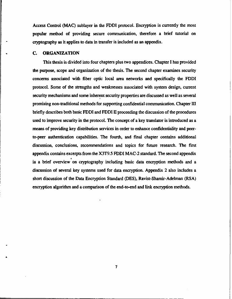
and to the world via WANs, (see Figure 2) it becomes obvious that the so called
"environment of trust" is not really valid. An environment based on trust is quickly
weakened when users are no longer aware of who may have access to their system.
•[• "• FDDI-I"AIN/MAN Ring Token Ring LMN
Expressnet LMA
Computur Work Stations
Figure 2. Interconnected Network System
8
Another consideration is that complex security devices used for highly classified
information may not be appropriate for the average LAN. The value of the data on these
networks may not warrant the added time complexity or monetary cost required of these
security devices, and consequently may make them an unacceptable solution. This is a
particular concern when we consider the electro-optic bottleneck problem caused by the
mismatch in speeds of the high speed fiber optic medium and slower electronic
components.
Security devices need to better accommodate the needs of the user application
and network design in order to keep up with changes in the industry. Currently the IEEE
802 standard employs the same security mechanism for all LANS sharing the same ISO
layers 3-7. [Stal 91] When the fundamental differences between the LANs which fall into
this category are considered,the need for more forethought in security design becomes
apparent.
Most LANs employ contention media access protocols which pose additional
security problems. In contention access systems, each transmission is "broadcast" on the
medium resulting in every party on the network having the potential to view all data in
transfer. Additionally, authentication of stations and messages is traditionally of lesser
concern in broadcast local area networks. LAN stations or nodes often represent single
users who are generally authenticated during login through passwords. In passive
contention designs, the "broadcast and capture" message protocol precludes any effective
challenge of message authenticity. Active contention LAN's such as token ring and FDDI
pose some different problems which will be discussed later in this paper.
2. Traffic Analysis
LAN's are highly susceptible to traffic analysis despite the fact that the message
contents may be protected by encryption. This is because the source and destination
addresses usually remain unprotected and readable by all stations. With each station
typically representing a single user, the passive intruder may acquire valuable information
9

by determining which users are communicating with one another. An obvious example
might be the problems encountered by the military trying to plan a surprise offensive. The
large volume of traffic to particular locations would likely indicate to the enemy that
something substantial is about to happen.
The two most common methods used to deter traffic analysis are to control the
routing of messages and to pad traffic by generating spurious messages for all possible pairs
of hosts. [Pfle 89] The "broadcast and capture" protocols of most local area networks make
the routing control method impractical for these systems, since all messages are available
to all stations on the net anyway. The message padding method implies a higher bandwidth
utilization which, in the case of passive contention protocols may reduce throughput by
potentially causing more collisions.
B. FIBER AND SECURITY
1. Electromagnetic vs. Light Energy
As electric current (possibly in the form of a digital signal) travels through wire
or cable a magnetic field is generated. Sophisticated electronic circuitry which is not even
in contact with (but in relatively close proximity to) the cable can be used to detect
electromagnetic emanations. The implications of these vulnerable emanations constitutes a
security threat. Additionally, copper wire and cable can easily be cut and spliced to
facilitate simple active wiretaps. Active wire taps not only allow intruders to listen but also
permit them to inject signals into the communication medium. [Pfle 89]
Optical fiber offers several distinct security advantages. Principally, the signal in fiber
is in the form of light rather than electromagnetic (EM) energy, consequently there is no
electromagnetic field which, in turn, means the signals are insensitive to electromagnetic
interference and are virtually impossible to tap inductively. Additionally, the entire optical
network must be carefully tuned each time a new connection is made. This makes it
difficult to make a physical tap without detection. Optical fiber with intruder detection
shieldings are available such as the U.S. National Security Agency (NSA) approved step
10
index system and bimodal graded index fibers. Both of these alaum fiber systems are
transparent to the user and have self testing capabilities. [Coom 91]
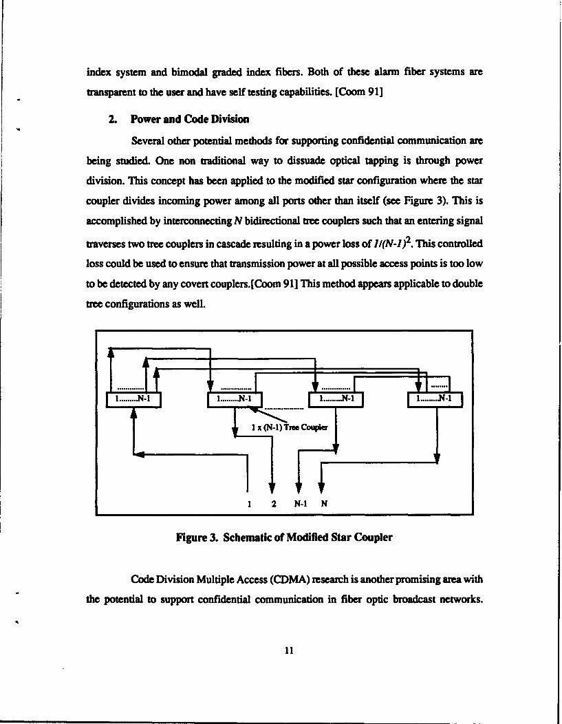
2. Power and Code Division
Several other potential methods for supporting confidential communication are
being studied. One non traditional way to dissuade optical tapping is through power
division. This concept has been applied to the modified star configuration where the star
coupler divides incoming power among all ports other than itself (see Figure 3). This is
accomplished by interconnecting N bidirectional tree couplers such that an entering signal
traverses two tree couplers in cascade resulting in a power loss of I/(N-1)2. This controlled
loss could be used to ensure that transmission power at all possible access points is too low
to be detected by any covert couplers.[Coom 91] This method appears applicable to double
tree configurations as well.
I.4- 1.....4-1 1..... -, ............... .I ... ... II .. .
l x(N-I)TreeCoupler
1 2 N-I N
Figure 3. Schematic of Modified Star Coupler
Code Division Multiple Access (CDMA) research is another promising area with
the potential to support confidential communication in fiber optic broadcast networks.
11

CDMA could be used as a replacement for, or a supplement to current data encryption
methods as a means of providing private communications. This method involves time-
multiplexing messages by transforming each pulse from a transmitter into a train of
secondary pulses by suitable coding means. Only those receivers with matched decoders
are therefore able to recognize the correct pulse sequences. [Marh 89]
Both of these methods are still being investigated to determine their validity and
feasibility. Consequently, commercial application using CDMA and power division as a
basis for maintaining communication security are probably still several years away.
However, as concerns surrounding the effectiveness of data encryption continue to surface,
these non traditional methods will likely gain more attention.
3. Optical Bidirtctionality
Optical fiber also possesses the property of optical bidirectionality (OB) wich
is the capability of simultaneous transmission in opposite directions on the same channel
without collision. The idea of using this physical characteristic as means of generating a
jamming signal transmitted to unintended stations has been suggested as a means of
providing a (non-conventional) privacy mechanism for passive broadcast FOLANs. The
OB method is not susceptible to cryptanalysis because the signal received at each station is
not ciphertext, but rather a superimposition of the jamming signal over the plaintext.
However, authentication is still facilitated through encryption and is thus subject to
cryptanalysis. This concept has been applied in theory to a wide variety of demand
assignment multiple access (DAMA) schemes using linear buses, binary trees and modified
star configurations while still maintaining the significant features of the access protocol.
This method is not really practical for the token ring or FDDI protocols. Since the most
obvious problems stem from the active contention access scheme and unidirectional
message passing at each station. Passing along a superimposed signal to the receiving
station with no way to reproduce the plaintext would be of little use. Overcoming this
problem would necessitate many modifications to the physical layer in terms retrofitting of
12

optical couplers. In addition, major modifications would be required at the media access
control (MAC) sublayer to the clocking synchronization scheme in order to facilitate
confidential call set up and termination. [Marh9l]
C. TOKEN RING ARCHITECTURE
In the token ring architecture it is possible for one node to deny service to another
node or to compromise integrity by either withholding a message or by modifying a
message before retransmitting to the next node. This is unlike typical broadcast networks
employing a bus architecture where each node must capture a message as it goes by. From
this perspective the security requirements of the token ring more closely resemble those of
many wide area networks. In the token ring architecture there is no provision to analyze
traffic flow. This means covert channels may go undetected and the authenticity of nodes
is not verified. The ring architecture possesses several intrinsic security advantages not
seen in other LAN architectures. The most obvious advantage is a known path between
every transmit/receive station pair. Every packet (message) must pass through every other
station on the ring and always terminates back at the transmitting station. This enables the
transmitting station to monitor the message after it has traveled through all stations and thus
check the integrity and availability of the message. The current FDDI standard incorporates
a Frame Check Sequence (FCS) using cyclic redundancy checks. [FDDI 91] The purpose
of the FCS is to permit the receiving station to determine whether the received message is
the same as the transmitted message. In this way the message can be checked for integrity
by both the receiving and transmitting stations. Figure 4 depicts a sample frame traversing
a ring with an error introduced as it passes through a station along its path. A simple modulo
2 addition operation applied between the message before transmission and the returning
message reveals the number and location of errors.
Although node authenticity is not verified in the ring architecture each node does
monitor all traffic, comparing source addresses of passing frames with its own address.
This allows originating stations to remove messages after they have traveled the entire ring
13
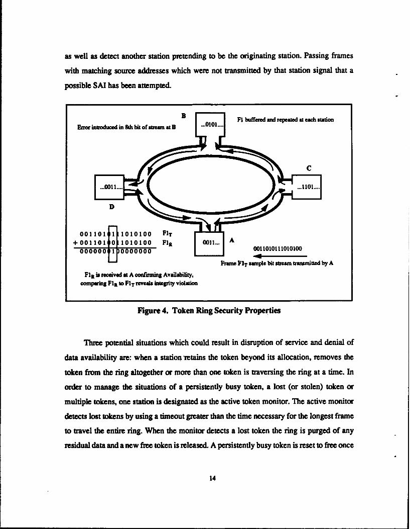
as well as detect another station pretending to be the originating station. Passing frames
with matching source addresses which were not transmitted by that station signal that a
possible SAI has been attempted.
B Fl buffered and repeated at each stationError introduced in Sah bit of stream at B
001101 1010100 FIT
+001101 0 1010100 FlR 0011... A
000000 0011010111010100
N~ 44Frame FIT sample bit stream tramsmitted by A
FlR is rceived at A confrming Availability,
comparing FlI to FIT reveals integrity violation
Figure 4. Token Ring Security Properties
Three potential situations which could result in disruption of service and denial of
data availability are: when a station retains the token beyond its allocation, removes the
token from the ring altogether or more than one token is traversing the ring at a time. In
order to manage the situations of a persistently busy token, a lost (or stolen) token or
multiple tokens, one station is designated as the active token monitor. The active monitor
detects lost tokens by using a timeout greater than the time necessary for the longest frame
to travel the entire ring. When the monitor detects a lost token the ring is purged of any
residual data and a new free token is released. A persistently busy token is reset to free once
14

detected by the active monitor. Other stations on the ring have the role of passive monitor.
Passive monitors must be able to detect active monitor failure and assume that role. A
contention- resolution algorithm is used to decide which passive monitor station takes over
in the event of active monitor failure. [Stal 91]
Figure 5. Dual Ring Adaptability
Another design feature of some ring architectures such as FDDI helps to alleviate the
problem of multiple points of failure within the network through the use of dual counter
rotating trunk rings. When a node or link fails the two counter rotating paths wrap together
around the fault thus allowing continued communication. Figure 5 depicts the dual ring in
the normal configuration as well as the wrap mode. This ability to adapt to breaks or node
failures helps ensure reliability of the system and availability of data in transfer. [Ross 89]
15
M. FDDI AND SECURITY
A. FDDI
The Fiber Distributed Data Interface (FDDI) is a 100 megabit per second (Mbps)
LAN using an optical fiber transmission medium. The stations are configured using two
counter rotating trunk rings which permits reconfiguration of the ring in the event of
failures. A total of 1000 physical connections (500 stations) and a fiber path of 200
kilometers has been used as the basis for calculation of recovery timer default values. Some
of the potential services offered by FDDI include I/O channel (back-end), LAN backbone,
front end high performance LAN, and circuit switched applications.
1. Basic FDDI
In Basic FDDI, a "free" token is passed from station to station to signify the ring
is available for transmission of information on the next frame. If a station wants to transmit,
it removes the free token from the ring. After the captured token is received, the station
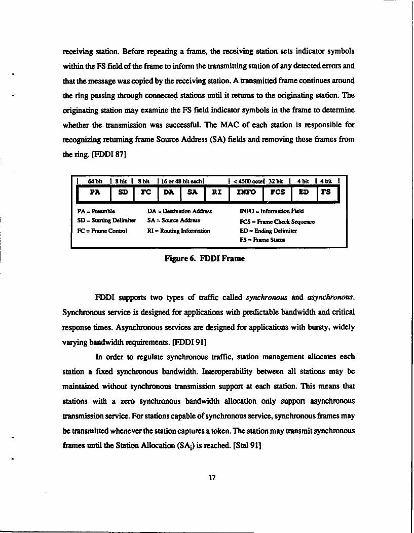
begins transmitting its eligible queued frames. Each frame starts with a preamble which is
at least 64 bits long. The preamble is followed by an 8 bit starting delimiter, an 8 bit frame
control, a 16 or 48 bit destination address and a 16 or 48 bit source address. The length of
the information field is variable, but is limited by the maximum frame length of 4500
octets. The information field is followed by a 32 bit frame check sequence, 4 bit end
delimiter and a frame status field. Figure 6 shows the format for an FDDI frame.
Immediately after transmitting a frame the station releases the token. This allows frames
from multiple stations to simultaneously propagate around the ring. [Ross 89]
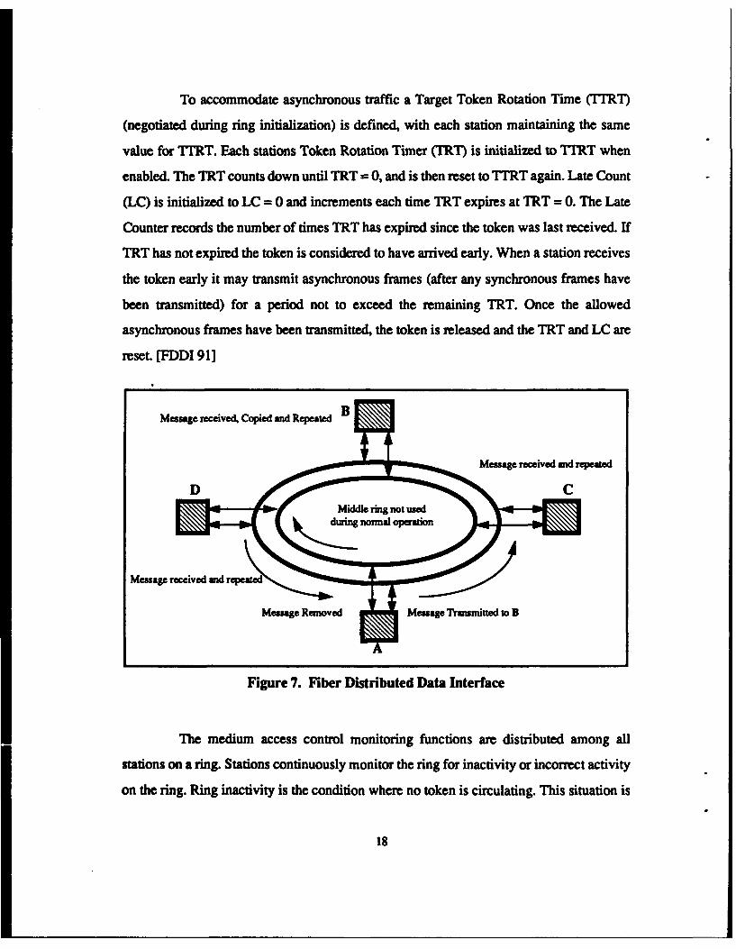
Ring operation consists of each station receiving frames from its upstream neighbor
station and transmitting (repeating) the frame to the next station downstream (see Figure
7). As a frame passes through a station, that stations MAC modifies indicator symbols in
the Frame Status (FS) field of the frame to indicate detection of any errors in the frame.
During the receive and retransmit operation, destination addresses of passing frames are
compared to the MAC's address. Matching frames are copied into a local buffer at the
16
receiving station. Before repeating a frame, the receiving station sets indicator symbols
within the FS field of the frame to inform the transmitting station of any detected errors and
that the message was copied by the receiving station. A transmitted frame continues around
the ring passing through connected stations until it returns to the originating station. The
originating station may examine the FS field indicator symbols in the frame to determine
whether the transmission was successful. The MAC of each station is responsible for
recognizing returning frame Source Address (SA) fields and removing these frames from
the ring. [FDDI 87]
1 64bit 1 8bit 1 8bit 116 or 48 bit eachl I <4500octed 32bit 1 4bit 1 4bit I
IPA I SDI FC DAISA I R I IN'o I cs IZ Eir19PA = Preamble DA = Destination Address IN = Information FieldSD = Starting Delimiter SA Source Address FCS = Rune Check Sequence
PC = Frame Control RI = Routing Information ED = Ending Delimiter
FS = Frame Status
Figure 6. FDDI Frame
FDDI supports two types of traffic called synchronous and asynchronous.
Synchronous service is designed for applications with predictable bandwidth and critical
response times. Asynchronous services are designed for applications with bursty, widely
varying bandwidth requirements. [FDDI 91]
In order to regulate synchronous traffic, station management allocates each
station a fixed synchronous bandwidth. Interoperability between all stations may be
maintained without synchronous transmission support at each station. This means that
stations with a zero synchronous bandwidth allocation only support asynchronous
transmission service. For stations capable of synchronous service, synchronous frames may
be transmitted whenever the station captures a token. The station may transmit synchronous
frames until the Station Allocation (SAi) is reached. [Stal 91]
17
To accommodate asynchronous traffic a Target Token Rotation Time (TIRT)
(negotiated during ring initialization) is defined, with each station maintaining the same
value for TTRT. Each stations Token Rotation Timer (TRT) is initialized to TIRT when
enabled. The TRT counts down until TRT = 0, and is then reset to TTRT again. Late Count
(LC) is initialized to LC = 0 and increments each time TRT expires at TRT = 0. The Late
Counter records the number of times TRT has expired since the token was last received. If
TRT has not expired the token is considered to have arrived early. When a station receives
the token early it may transmit asynchronous frames (after any synchronous frames have
been transmitted) for a period not to exceed the remaining TRT. Once the allowed
asynchronous frames have been transmitted, the token is released and the TRT and LC are
reset. [FDDI 91]
Message received, Copied and Repeated B
Message received and repeatedD C
duin normal operaion
Message received and repeated
Message Removed Message Transmitted t B
Figure 7. Fiber Distributed Data Interface
The medium access control monitoring functions are distributed among all
stations on a ring. Stations continuously monitor the ring for inactivity or incorrect activity
on the ring. Ring inactivity is the condition where no token is circulating. This situation is
18

remedied by purging the ring of all residual traffic and re.easing a new free token. Incorrect
ring activity is typically the result of successive expirations of the Target Rotation Timer
and Late Counter. The persistently busy token, once detected, is simply reset to a free token
by a monitor station.
Station Management (SMT) at each MAC, monitors ring activity and exercises
control over station activity during ring operation. In the event that SMT detects a failed
station, the network is reconfigured at either end of the faulty link. This removes the node
from the network and allows continued operation of the ring. [Ross 89] The process of
removing a faulty link is called wrapping and is depicted below in Figure 8.
Station C fails at both rings
The two rings wrap formingone large ring.
Figure 8. FDDI in the Wrap Mode
2. FDDI-I
FDDI-ll is an upward compatible enhancement of basic FDDI, which includes a
circuit switching capability called isochronous transmission. The primary difference
between basic FDDI and FDDI-il is the addition of a hybrid mode of operation specified in
the Hybrid Ring Control (HRC) document. HRC provides multiplexing of packet and
circuit switched data on a shared FDDI medium. FDDI-II permits stations to operate in
19
either Basic Mode or in Hybrid Mode. The Hybrid Mode differs from the Basic Mode in
that portions of the available bandwidth may be dynamically partitioned for circuit
switched data in units of full duplex Wideband Channels (WBCs). WBCs provide a
bandwidth division mechanism between the packet (synchronous and asynchronous)
switched traffic and circuit (isochronous) switched traffic. Up to 16 WBCs may be assigned
with each allocated up to 6.144 Mbps. The aggregate of any or all allocated WBCs may be
used as one virtual service to satisfy the needs of applications with large bandwidth
requirements such as high resolution video. [Ross 89] Using the 'hybrid' mode, data can be
multiplexed between the packet MAC and the isochronous MAC (I-MAC). The
transceiver, cable and connector systems are identical between FDDI and FDDI-l. With
some of the bandwidth in the FDDI-H ring possibly allocated to isochronous services
provided by the WBCs, additional services requiring virtual circuit switched services not
found in basic FDDI are possible. The most obvious services include video, voice and
control or sensor data streams.
B. CONFIDENTIALITY AND FDDI
1. Modification Design Issues
In Chapter I the implementation restrictions dictating the use of existing
commercial encryption standards to meet the needs of current high speed applications were
discussed. In addition, the proposed modification was supposed to maintain the integrity of
the FDDI protocol as much as possible. Consequently, some of these restrictions were
critical factors in several of the design decisions for the proposed protocol modification.
The FDDI standard is becoming much more established with networks already
in use. Any proposed modification decision must be tempered with the understanding that
the effect on existing systems and applications must be minimized in order for the
modification to be considered viable. Substantial changes to a protocol can easily result in
a cascading effect where the original protocol becomes barely recognizable. Our proposed
modification is at the MAL sublayer of the FDDI protocol. The changes to the protocol
20

entail the addition of several procedures for encrypting and decrypting data packets. The
use of these procedures results in an additional machine state for both the MAC transmitter
and receiver. In addition, some additional hardware would be required to perform the high
speed encryption and secure storage of keys. Additionally, one node on the ring must be
dedicated to key distribution services and is required to be a trusted facility. However, the
basic timing, fault management and frame management protocols have essentially
remained unchanged.
Public key encryption systems have been shown to be at least as secure and often
more memory efficient than private key systems for many types of applications. However,
several factors surrounding public key encryption led to the decision to use a private session
key mechanism and a modified conventional key server for key distribution. One of the
design restriction is that any modification be consistent with the speed and bandwidth
requirements associated with current and near future applications. Some of these
applications will include high resolution video conferencing, circuit switched voice and
data graphics capabilities. The rapid response time and large bandwidth requirements of
these applications make a public key system inappropriate for encryption of data packets
used in confidential communication. Public key systems require a double encryption/
decryption to provide both peer-to-peer authentication and secrecy. [Pfle 89] The double
encryption constraint coupled with the speed complexity of the ciphers (see Appendix 2)
make the response time of public keys unacceptable for many of the potential applications
to be used.
A public key distribution mechanism could be used to distribute private session
keys possibly more securely and as efficiently as a private key distribution system.
However, with the exception of the Rivest-Shamir-Adelman (RSA) encryption, the public
key algorithms seen to date have been shown to exhibit substantial weaknesses (see
Appendix 2). [Pfle 89] This is where we must consider the design restriction to use existing
commercial encryption standards. Unfortunately, the RSA encryption algorithm is not a
commercial standard but rather proprietary in nature. In addition to violating one of our
21
basic design restrictions, the use of a proprietary system in our design would necessitate
paying royalties to the patent holder.
For the reasons just presented our proposed modification is based on the use of a
conventional key system such as the Data Encryption Standard (DES). The DES is a readily
available commercial standard developed for government use and has undergone extensive
study and testing. Although we are not endorsing the DES, it represents the model
encryption standard for our proposed modification. In order to meet the needs of real time
applications we shall pay particular attention to the stream cipher mode of the DES.
2. MAC Level Implementation
As explained earlier, the FDDI protocol possesses many characteristics naturally
conducive to supporting secure communications. The token ring protocol provides the
added message integrity and availability through fault management, error checking and
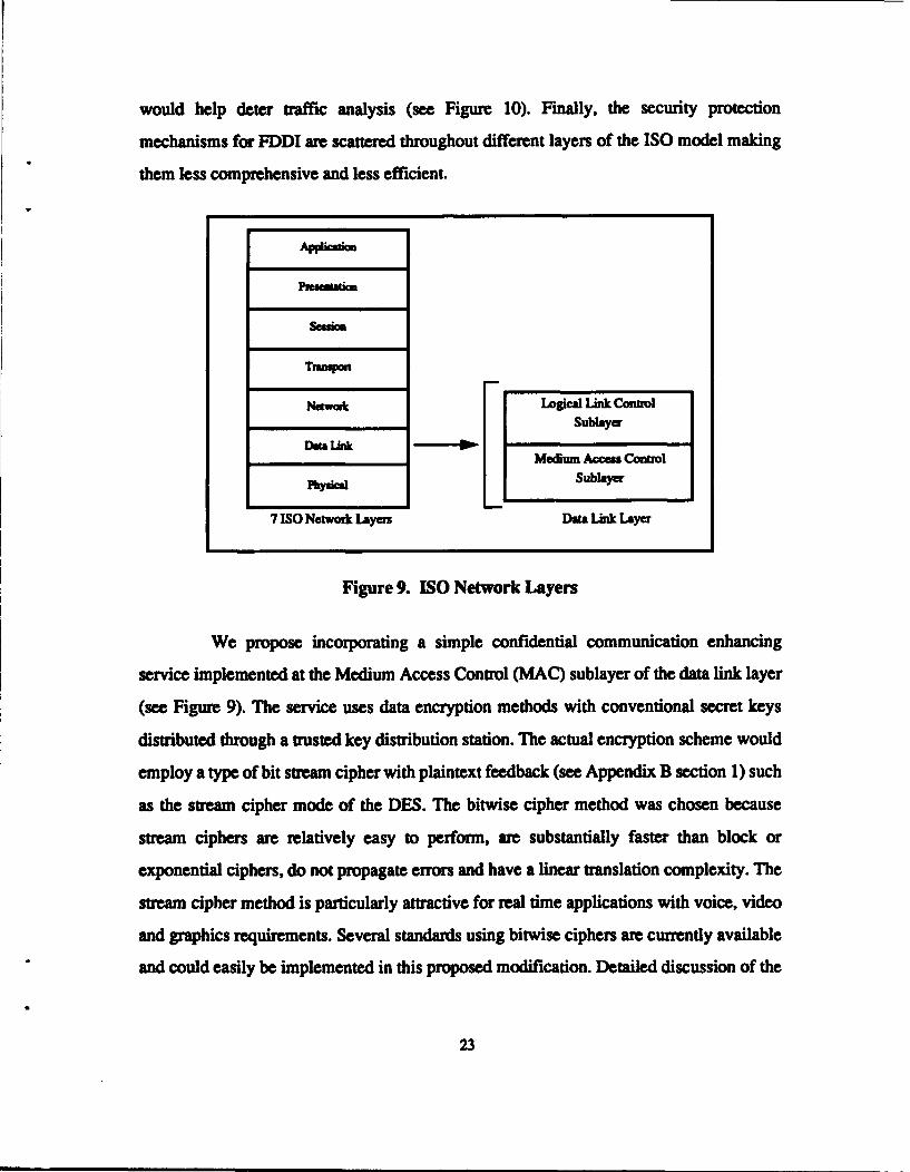
station management. However, confidentiality services in FDDI are not provided as part of
the FDDI protocol. In fact, privacy mechanisms for most LANs are traditionally facilitated
through encryption at the Logical Link Control (LLC) sublayer or higher layers in the ISO
model (see Figure 9). [Tard 85]One problem with this approach is that the same LLC is
used for a variety of LAN architectures including Carrier Sense Multiple Access/Collision
Detection (CSMA/CD), token bus, token ring, FDDI and several others. Performing
encryption at this level does not exploit the specific characteristics of the protocol or
topology. Several of the oldest most established LAN standards employ a passive
contention "broadcast and capture" protocol. The "receive and forward" design of the token
ring more closely resembles the point-to-point characteristics seen in many wide area
networks. Using the same confidential communication system for such different systems
seems grossly inappropriate.
In addition to the points just discussed, it should be mentioned that address
recognition is facilitated at the MAC sublayer. Therefore, the Source Address and
Destination Address of the private frame can never be encrypted at the LLC sublayer which
22
would help deter traffic analysis (see Figure 10). Finally, the security protection
mechanisms for FDDI are scattered throughout different layers of the ISO model making
them less comprehensive and less efficient.
T=m~
Trnsp~on
Netwak Logical Link ConUolDo& link Sublayea
Medium Access ControlPy Subhyer
7 ISO Network Layers Data Link Layer
Figure 9. ISO Network Layers
We propose incorporating a simple confidential communication enhancing
service implemented at the Medium Access Control (MAC) sublayer of the data link layer
(see Figure 9). The service uses data encryption methods with conventional secret keys
distributed through a trusted key distribution station. The actual encryption scheme would
employ a type of bit stream cipher with plaintext feedback (see Appendix B section 1) such
as the stream cipher mode of the DES. The bitwise cipher method was chosen because
stream ciphers are relatively easy to perform, are substantially faster than block or
exponential ciphers, do not propagate errors and have a linear translation complexity. The
stream cipher method is particularly attractive for real time applications with voice, video
and graphics requirements. Several standards using bitwise ciphers are currently available
and could easily be implemented in this proposed modification. Detailed discussion of the
23
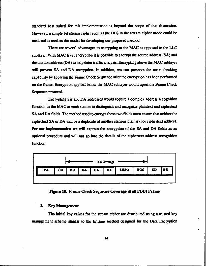
standard best suited for this implementation is beyond the scope of this discussion.
However, a simple bit stream cipher such as the DES in the stream cipher mode could be
used and is used as the model for developing our proposed method.
There are several advantages to encrypting at the MAC as opposed to the LLC
sublayer. With MAC level encryption it is possible to encrypt the source address (SA) and
destination address (DA) to help deter traffic analysis. Encrypting above the MAC sublayer
will prevent SA and DA encryption. In addition, we can preserve the error checking
capability by applying the Frame Check Sequence after the encryption has been performed
on the frame. Encryption applied below the MAC sublayer would upset the Frame Check
Sequence protocol.
Encrypting SA and DA addresses would require a complex address recognition
function in the MAC at each station to distinguish and recognize plaintext and ciphertext
SA and DA fields. The method used to encrypt these two fields must ensure that neither the
ciphertext SA or DA will be a duplicate of another stations plaintext or ciphertext address.
For our implementation we will express the encryption of the SA and DA fields as an
optional procedure and will not go into the details of the ciphertext address recognition
function.
I"FCS Coverage .1
PA I8D IFC I DAISAIRI I kIwo lircsl ITS I
Figure 10. Frame Check Sequence Coverage in an FDDI Frame
3. Key Management
The initial key values for the stream cipher are distributed using a trusted key
management scheme similar to the Erhsam method designed for the Data Encryption
24
Standard (see Appendix B section 3). [Ehrs 78] As discussed earlier, this is one possible
alternative to using a public key distribution system. This unique variation is based on a
secure node called the Central Key Translator (CKT). A key generator is used by the
transmitting station A to generate a unique 64 bit initialization value called KIv. A 64 bit
value was chosen primarily because that is the length used in the DES. However, an
encryption method using a different length key could be implemented for use with some
other encryption standard as long as it did not exceed the maximum frame length for FDDI
(4500 octets). The initial key value is encrypted using the master key KtA shared only by
the transmitting station A and the Central Key Translator (CKT). Upon receiving the
encrypted IVAB value, the CKT decrypts the frame using master key KtA and then re-
encrypts on the same frame using master key Ktg of the receiving station B. The translated
key is then forwarded to Station B which uses the master key KtB to decrypt the translated
initial key KIV value originally generated by A. Station B copies the flagged frame,
generates a session key value by invoking a GENERATEKEY procedure involving a
Pseudo Random Number Generator (PRO). At the same time B decrypts the frame
(containing initial key value) just received from the CKT. Station B then uses the received
initial key KIV (generated by A) to encrypt the session key it just generated. B's new key
is then forwarded on to A encrypted under a key only stations A, B and the CKT share.
Station A recognizes the returning frame and removes it from the ring. The frame is
decrypted by A using the initial key KIv (which A generated). Both stations A and B now
share the same session key and may conduct confidential communication. Since the frame
is removed by station A even the CKT does not posses the session key. The session keys
were distributed with one traversal of the ring. The other situation is when the receiving
station is logically positioned before the CKT. In this case key establishment would require
two ring traversals. On the average the two station positioning situations will each occur
50% of the time resulting in an average of 1.5 ring traversals for key establishment. This is
still one half the number of frame transmissions required for key establishment using the
25
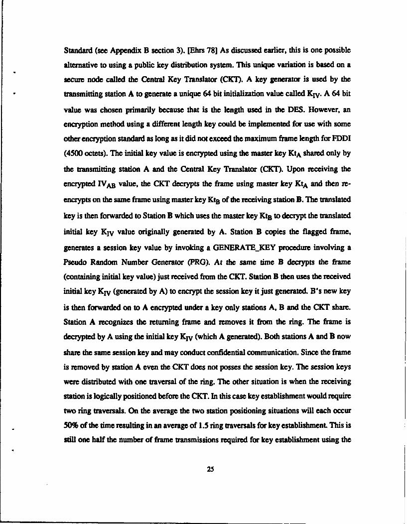
conventional key server described in Appendix 2. The protocol for the Central Key
Translator operation is depicted graphically in Figure 11.
2. CKT decrypts initial key Krv,me-amrpt using KtB the
4.Statiom AandB cmcoiduct forewords frame to B
confidential comnumnicatioi
using uinion key KS. 0% _ _]
3. B gamat session key K1 aid sends toA encylted undeintal key K, Arnoves fame from rmg mid uses theinitial key Kv to deayp A nd B nowshire sessio key Ks. The CKM does no.
A
1. A generates initial key KrV andsends to CKT encrypted widermastur key KtA
Figure 11. Central Key Translator Protocol
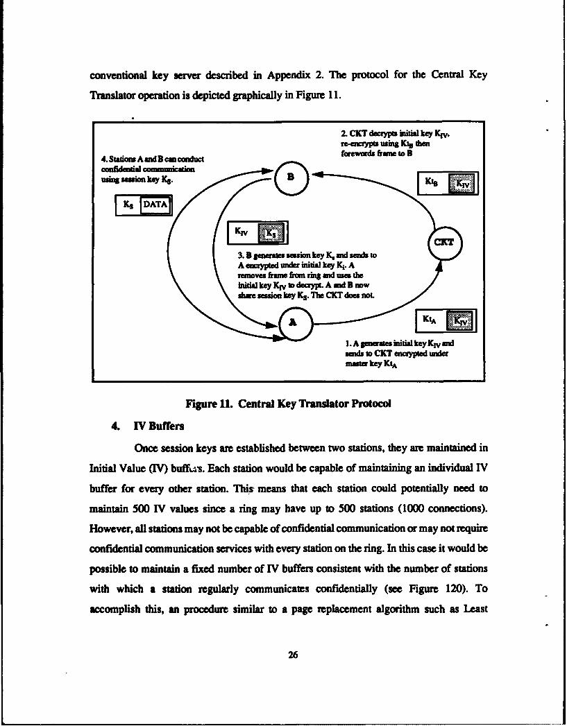
4. IV Buffers
Once session keys are established between two stations, they are maintained in
Initial Value (IV) buffvs. Each station would be capable of maintaining an individual IV
buffer for every other station. This' means that each station could potentially need to
maintain 500 IV values since a ring may have up to 500 stations (1000 connections).
However, all stations may not be capable of confidential communication or may not require
confidential communication services with every station on the ring. In this case it would be
possible to maintain a fixed number of IV buffers consistent with the number of stations
with which a station regularly communicates confidentially (see Figure 120). To
accomplish this, an procedure similar to a page replacement algorithm such as Least
26

Frequently Used (LFU) or Last Recently Used (LRU) could be implemented to manage
which buffers would be overwritten when a particular IVAB did not exist Any station
overwriting an existing key value must notify the station sharing the overwritten key that it
is no longer valid. Otherwise, a transmitting station may send data frames encrypted using
a key which the receiving station is no longer maintaining. By maintaining key values for
station pairs we reduce the requirement for establishing a new session key each time a
private communication is initiated. This is a fundamental requirement for use with rapid
response time applications. The added secure memory requirement for maintaining session
keys is the trade-off for this speed improvement.
In order to prevent a session key from becoming "stale" the key is changed after
each received frame or series of received frames based on a pre-negotiated frame interval
established between the transmitting and receiving stations. This session key generation is
accomplished by using part of the plaintext from one of the INFO frames (previously
negotiated) as a seed used for generating a new session key. Both the transmitting and
receiving stations may generate the session key independently (without the CKT) provided
the receiving station copies an error free message. In the event that an error is introduced
in the frame intended to be used for key generation, both stations will be able to detect the
error(s) and the previous key can be used one more time or the CKT can be used to reset
the keys. The error stricken message may then be retransmitted using the same or different
keys depending on the protocol. By generating a new key with each received frame or series
of received frames, each key serves as a short term cipher. Periodically, the keys should be
reset using the CKT even when a valid TV exists between two stations. Since all stations
possessing the same key seed are capable of generating the same key it is imperative that a
limited amount of cipher text under the same key be provided any cryptanalytic intruders.
Consequently, only by maintaining the secrecy of the keys can we more assuredly guard
the secrecy of the messages.
27
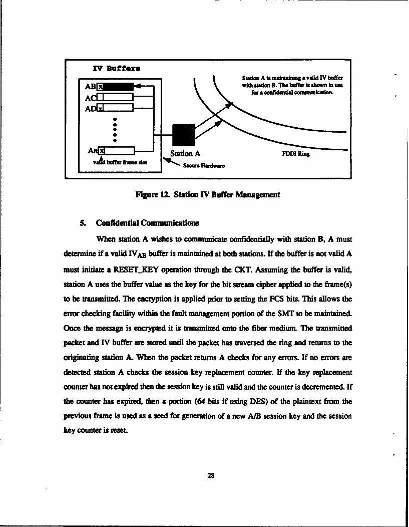
IV Ruff.e:Swics A is inaidan a valid IV buffer
AB ~with staion 3. The buffer is shown in use
vStation A FM Ring
va& uffr ft sWSao=u Hardware
Figure 12. Station IV Buffer Management
5. Confidential Communications
When station A wishes to communicate confidentially with station B, A must
determine if a valid IVAB buffer is maintained at both stations. If the buffer is not valid A
must initiate a RESETKEY operation through the CKT. Assuming the buffer is valid,
station A uses the buffer value as the key for the bit stream cipher applied to the frame(s)
to be transmitted. The encryption is applied prior to setting the FCS bits. This allows the
error checking facility within the fault management portion of the SMT to be maintained.
Once the message is encrypted it is transmitted onto the fiber medium. The transmitted
packet and IV buffer are stored until the packet has traversed the ring and returns to the
originating station A. When the packet returns A checks for any errors. If no errors are
detected station A checks the session key replacement counter. If the key replacement
counter has not expired then the session key is still valid and the counter is decremented. If
the counter has expired, then a portion (64 bits if using DES) of the plaintext from the
previous frame is used as a seed for generation of a new A/B session key and the session
key counter is reset.
28
When the confidential message reaches the receiving station B, if no errors are
detected it sets the proper indicator symbols in the Frame Status field and retransmits the
frame. Station B's MAC then applies the bit stream cipher to the ciphertext frame just
received using the value stored in the IV buffer as the session key. If the session key counter
has expired, a portion of the resultant plaintext message (64 bits if using DES) is used as
the seed for generating a new session key, the new key is copied into B's IVAB buffer and
the session key counter is reset. If the session key counter has not expired, then the session
key remains valid and the key counter is decremented. If errors are detected, the proper FS
field indicator symbols are set, the frame is retransmitted to the next station and the current
session key is maintained as valid. The confidential frame may be retransmitted under the
current session or may be encrypted under a new session key following a RESETKEY
operation.
6. Security Procedures
a. CALL SETUP
The call set up is initiated when station A attempts to transmit a confidential
message to station B. The procedure begins when A has captured the token and recognized
the queued frame(s) to be sent as confidential. Assuming each station maintains a unique
IV buffer for every other station capable of confidential communication, A would check to
see if a valid buffer value exists. If the buffer value is valid, A would use the value as the
session key KS for the SECURE_'X procedure. For an invalid IV buffer value, A would
temporarily store the confidential CFRAME, then initiate the RESETKEY procedure.
h. RESET-KEY
RESET_KEY can be initiated by either the receiving or transmitting station.
The RESET-KEY procedure must be performed following system initialization, whenever
the transmitter/receiver pair session key is not valid, when the session key counter has
expired and optionally after an error is detected in a CFRAME by either station. During
29
the RESETKEY operation the basic protocol described for the Central Key Translator is
invoked. A key generator is used by the transmitting station A to generate an initialization
vector (TV) value called IVAB. This value is encrypted using the master key KtA shared
only by A and the CKT. Upon receiving the encrypted IVAB value, the CKT decrypts
using KtA and then re-encrypts using KtB. The translated key is sent to B on the same
frame. Station B uses the master key KtB to decrypt the translated frame from A. Station B
then generates another key value. The new key value is retransmitted in the same frame
onto the ring encrypted using the key just received from station A. Upon receiving the key
frame from B, station A removes it from the ring.
c. SECURETX
The SECUREJTX procedure is used by the transmitting station A
attempting to transmit CFRAME(s). Once a valid IVAB is established between the two
stations, the station A applies the stream cipher function to the C_FRAME. Once it is
encrypted A transmits the encrypted CFRAME to B using the IVAB as the session key.
The encrypted frame(s) travels around the ring passing through all stations connected to the
ring until returning to A. The recognized CFRAME(s) are stripped from the medium by
A. Station A then checks the indicator symbols, and compares the frame(s) to the original
transmission to ensure the integrity has been maintained. A frame that does not return or is
modified suggests a security violation.
d SECURERC
SECURERC is the procedure invoked by a receiving station B upon
recognition of a CFRAME with a matching destination address. The frame is copied,
checked for errors, appropriate frame status field bits set and then retransmitted. If errors
were detected B will maintain the last valid IVAB and wait for a retransmital or a
RESET_KEY operation followed by retransmital. Assuming no errors are detected B
invokes the SECURE_RC procedure. The C_FRAME which was copied into the local
30
buffer LBB is decrypted using the stream cipher with IVAB as the session key. If the session
key counter has not expired, the IVAB value is maintained, the counter is decremented and
the normal FDDI protocol for the receiver resumes control. If the counter has expired a
portion of the plaintext INFO field is used as a seed to generate a new session key and the
session key counter is reset.
e. GENERATE_KEY
This procedure is used by cryptographic equipped stations to generate new
session keys. The procedure may be used as the initial key during a RESETKEY
procedure or when the session key counter has expired to generate a new session key. When
used during the RESET_-KEY operation the input for the function is generated by a random
number generator. When used to change an existing session key the input for the function
is part of the plaintext (64 bits) from the previous message.
.f. Procedure Notes
[Denotes optional step)
-- Denotes a comment --
Type field is BitLStringType FDDlframe is
RecordPA: Preamble..Field;SD, ED: Delimeter.FieldDA, SA: Address_Field;RI: Routing_InfoField;INFO: InfonmationField;FCS : FrameCheck._SequenceField;FS : FrameStatus..Field;
end Record;C-FRAME, KFRAMELBB : Type FDDlframe;KEY-SEED, PRG : Type KEYINPUT;IV, KtA, KtB : Type KEY;A, B, CKT: Type Station;SESSIONJKEY-COUNTER : Type INTEGER;ENCRYPT, DECRYPT: function STREAM-CIPHER;
31

I.RESEL-KEYTransmitting Station A:
(IVAB):= (GENERATE KEY(PRG));
Kj..RAME.INFO= IVAB;TX to CKT(ENCRYPT((KtA( K.FRAME)))); --key is sent CKT under A's masterkey--
CKT Station:RC(ENCRYPT(KtA(K-FRAME)));
DECRYPT (KtA( ENCRYPT (KtA(K-FRAME)))); --key decryptad using A's master key--
TX to B: ENCRYPT (KtB(KFRAME); --key re-encrypted and sent under B's master key--
Receiving Station B:RC from CKT(ENCRYPT(KtB(K...FRAME));
(IVAB):= DECRYPT (KtB(ENCRYPT(KtB(K-YRAME.INF));K5 := GENERATýEKEY(PRG); -B generates new key--
TX TO A: ENCRYPT(IVAB(KS)); --new session key sent using IVAB as key--
end Reset-Key;
2. SECUREJTXIF C-JRAME queued for TX THEN
ENCRYPT(((C.fRAME.DA, C..YRAME.SA) ,C_FRAME. INFO));SET FCS (CjRAME);TX to B (CJRAME);IF SESSION -KEY-COUNTER = 0 THEN -- counter expired --
KEY-SEED:= (l..64(CYRAME.IN4FO));(IVAB):= (GENERATE_.KEY(KEYSEED));,RESET( SESSIONKEY-.COUNTER);
ELSE -- increment counter -
SESSIONKEY_COUNTER --- SESSIONj_KEY_COUNTER -1;END IF;
end loop;end SECURETX;
3. SECUREL.RC isIF C...FRAME RX and IVAB VALID THEN
CHECK FCS (CFRAME);EF CJFRAMdEERROR THEN
SET FRAME...STATUS-.BITS(ERROR);TX to A (C.YRAME);MAINTAIN-KEY (RESELýKEY);EXIT SECURELRC;
END IF;,LEB := C-YRAME.;
32

SET FRAMESTATUSBITS(COPIED);TX to A (CFRAME);DECRYPT (LBB );
IF SESSION_KEYCOUNTER = 0 THEN
KEY._SEED:= (I..64(LBB .INFO));
(IVAB):= (GENERATEKEY(KEYSEED));
RESET( SESSIONKEYCOUNTER);ELSE
SESSIONKEYCOUNTER:= SESSION_KEYCOUNTER -1;
END IF;ELSE IF CFRAME RX and IVAB NOT VALID THEN
NOTIFY TRANSM'ITING STATION IVAB NOT VALID
END IF;
end SECURERC;
4. CALL_SETUPIF IVAB VALID THEN
SECURETX(AB);ELSE
RESET_ KEY (AB);END IF;
end CALL._SETUP;
7. MAC Modifications
Implementation of the proposed confidential communication service at the MAC
level would require some modifications to the protocol. These modifications include
introduction of some additional variables and procedures which were mentioned in the
previous section. In addition, the state transitions within the MAC receiver and MAC
transmitter will also require some modification. These modifications entail creating an
additional machine state for both the MAC receiver and MAC transmitter. Both of these
states represent intermediary points where key establishment and encryption/decryption are
facilitated. Aside from these two additional states, the MAC level protocol remains
basically intact. The complete receiver and transmitter state transition diagrams as well as
abbreviations and algorithms for FDDI MAC-2 are located in Appendix B.
33

a. MAC Receiver Transitions
Modifications to the receiver state transition machine are required to
implement the MAC level security enhancing modification. For MAC receiver
modification, a new machine state called RC._SECURE is introduced. This state is an
intermediary between RCFR CTRL and RCFRBODY. There are two possible
transition paths between RCFR_CTRL and RCSEC_BODY. The first transition occurs
when the MAC recognizes the frame as containing a new key which must be decrypted. The
second transition occurs when a confidential frame (CFRAME) is recognized by the flag
bit set in the frame control slot. Transition to the RC_FRBODY occurs after the
C_FRAME has been decrypted or a new key is decrypted.
R3: DYB ctions
R2: RC TR CTRL R6: RCSECBODY
(26a) RCNEWKEY Do
KFRAME R(63) P'rxFrame
R(26b) CFRAME NEWKEY
Figure 13. Modified MAC Receiver State Diagram (States Affected)
b. MAC Transmitter Transitions
In order to facilitate the implementation of the confidential communication
device, some fundamental modifications to the MAC must be considered. On the
transmitter side of the house, an additional machine state is developed. This sixth machine
state is called T6: SEC_TX_SETUP and is an intermediary state between the TO: TXIDLE
and T2: TX_DATA states. The purpose of the SECTXSETUP state is ensure all
preliminary requirements for a secure transmission are met. Transition to
SECTXSETUP occurs from the TXIDLE state when the next queued frame is flagged
34
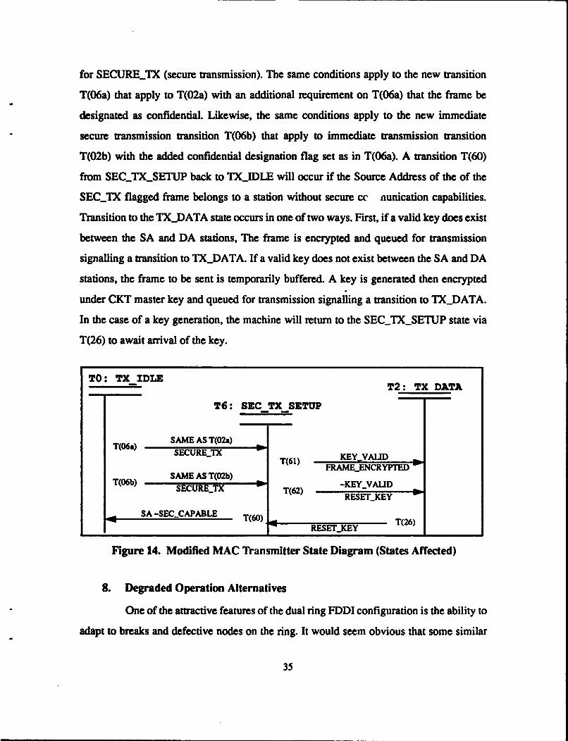
for SECURE_TX (secure transmission). The same conditions apply to the new transition
T(06a) that apply to T(02a) with an additional requirement on T(06a) that the frame be
designated as confidential. Likewise, the same conditions apply to the new immediate
secure transmission transition T(06b) that apply to immediate transmission transition
T(02b) with the added confidential designation flag set as in T(06a). A transition T(60)
from SEC_TX_SETUP back to TX_IDLE will occur if the Source Address of the of the
SECTX flagged frame belongs to a station without secure cc aunication capabilities.
Transition to the TX_DATA state occurs in one of two ways. First, if a valid key does exist
between the SA and DA stations, The frame is encrypted and queued for transmission
signalling a transition to TX_DATA. If a valid key does not exist between the SA and DA
stations, the frame to be sent is temporarily buffered. A key is generated then encrypted
under CKT master key and queued for transmission signalling a transition to TXDATA.
In the case of a key generation, the machine will return to the SEC_TX_SETUP state via
T(26) to await arrival of the key.
TO: TX IDLET2: TX DATA
T6: SEC TX SETUP
SAME AS T(02a)T(06a) SEUEJSECURETX T(61) KEYVALID
FRAME-ENCRYPTEDSAME AS T(02b)
"T(06b) -KEYYALIDSECURETX T(62) RESELKEY
SA -SECCAPABLE T(60) h T(26)F RESEr-KEY
Figure 14. Modified MAC Transmitter State Diagram (States Affected)
8. Degraded Operation Alternatives
One of the attractive features of the dual ring FDDI configuration is the ability to
adapt to breaks and defective nodes on the ring. It would seem obvious that some similar
35
constraints should be imposed upon any mechanism designed to support confidential
communication. In other words, what are the implications of losihig the CKT node in the
previously described design addition? The most obvious alternative would be to continue
using the current keys stored in the IV buffers. This would work relatively well assuming
valid keys were already established between stations needing confidential communication.
However, this an optimal situation and probably not realistic for long periods without the
CKT. Several other viable alternatives exist which could be implemented relatively easily.
A simple method to improve the reliability and availability of the system using
the CKT would be to include multiple CKT stations. If the primary station becomes
inoperable then a secondary station would take over the key translation process. The most
effective positioning of a second CKT would be 180 degrees out of phase with the primary
translator. This would reduce the likelihood of losing multiple CKTs if a large section of
the ring was to fail. However, cost of this redundancy is that fewer operational stations are
available.
Although, losing multiple CKT stations simultaneously is less likely, it is
possible. Therefore, some other method should be considered for providing some secure
communication capability during more serious degraded modes. One possibility is to have
a regular station act as a surrogate key translator. This would require that the station
maintain valid keys with both of the communicating stations. These would essentially serve
the same purpose as the master keys shared between stations and the CKT. A station acting
as translator must also be equipped with the logic to perform the rapid decryption/re-
encryption process. The same node would not need to act as translator for all station pairs.
In fact, only transmitting and receiving stations would be able to determine which stations
shared the necessary keys to perform the transaction. In addition, the work load of
becoming translator for all stations could greatly inhibit the communication performance
of that station.
36
IV. CONCLUSIONS AND RECOMENDATIONS
A. DISCUSSION
The token ring protocol of FDDI offers a number of security advantages over many
other LAN architectures. The principle advantage is that traffic can be regulated by
allowing stations to transmit differing amounts of data when controlling the token and by
permitting higher priority stations the opportunity to have first claim on a circulating token.
The fault management and error checking capabilities provided by FDDI are performed by
the MAC monitors at each station to ensure the integrity and availability of message
frames. The ability of the ring to shift to a wrapping mode in the event of node failure
greatly adds to the survivability and adaptability of the system.
The potential of FDDI for larger LAN and MAN uses is greatly enhanced with a 100
Mbps bandwidth and greater geographical coverage potential. In addition, the media access
protocol of FDDI more closely resembles the point-to-point characteristics of wide area
networks which typically have different security requirements than local area networks.
Currently the IEEE 802 standard for LANs provides an encryption mechanism at the LLC
sublayer of the Data Link layer. These mechanisms are more consistent with basic passive
contention access protocols than point-to-point systems. Rather than having to rely on a
generic LAN security device, a privacy mechanism integrated at the MAC level could more
effectively meet the specific high performance needs of FDDI networks. By incorporating
a privacy mechanism at the MAC sublayer, we establish a comprehensive security package
within the same sublayer which supports the three security elements of integrity,
availability and confidentiality.
Within the confines of the design restrictions outlined in Chapter I we have proposed
the integration of a MAC level privacy mechanism. The proposed modification should be
capable of meeting the high performance demands of current and emerging applications
while still maintaining the basic integrity of the FDDI standard protocol. In addition, the
37

modifications could be implemented using existing commercial encryption standards such
as the Data Encryption Standard (DES).
The implementation restrictions stated in Chapter Ill were determining factors in
several of the design decisions. The need for a key server could have been eliminated by
using a public key system for key distribution. However, the restriction to employ non-
proprietary standards precluded the use of the RSA algorithm. Other public schemes have
shown substantial weaknesses or have not undergone the intense scrutiny necessary to
instill a high confidence level. Use of a public key distribution scheme as a MAC level
privacy mechanism should be explored as a future research project.
The proposal to use a key generating facility at each station would incur
considerable cost overhead. A traditional key server system provides only the server with
a cryptographic facility. The problem with the conventional server is that the server station
has access to all the initial session keys. Using the CKT method does not allow the server
access to initial session keys and therefore removes the capability of the server station to
access confidential messages. Additionally, the proposed central key translator is more
consistent with conventional key server used for the DES.
In terms of overhead, the primary difference between public and private key
system storage and access requirements is that public keys may be stored in regular
memory, where private keys must be kept in secure (private) memory. The actual memory
and access requirements are essentially the same between the two systems. Public key
systems use more complex encryption methods which typically makes them slower.
However, for key distribution the exponential time overhead may be acceptable.
As mentioned in Chapter I, this proposed security enhancement package is not
intended to be an end all solution to replace other LAN security devices in use. The
proposed MAC level modifications are intended only as a foundation model for further
study and development. Any eventual implementation of a modification such as that
proposed must follow an evolutionary path of development. Other issues and concerns not
addressed in this thesis will likely influence future design and implementation decisions.
38
B. FUTURE RESEARCH
The dynamic nature of the information systems industry necessitates ongoing
evaluation and updating of security considerations. As new technologies and applications
emerge, new security requirements and concerns are raised. This thesis has touched on
some of the problems observed in the design and implementation of security enforcing
methods. However, many other areas of development remain to be researched. Several
possible directions for future research will be discussed.
The effects of incorporating a MAC level security device could be analyzed by
modifying an existing FDDI computer simulation or by developing a completly new
simulation to validate the assertions made in this thesis, uncover any problems not yet
addressed and analyze modified system performance.
As mentioned in this thesis, a MAC level encryption device provides the potential for
source and destination address encryption. In order to facilitate an encrypted address
scheme, several problems must be addressed. Any encrypted address must not duplicate a
plaintext addresses used by any station on ring. In addition, encrypted addresses must not
duplicate any ciphertext address currently in use. The problem of duplicate ciphertext
address is more complex because these addresses are not static and must not be easily
associated with individual stations to be effective. The development of an address
encryption scheme would require a complex MAC level address recognition function.
Providing this capability would greatly help to deter traffic analysis and add to the overall
effectiveness of the security enhancement package.
The restrictions stated in this thesis led to a design decision to use a key server for
distributing keys. Several public key distribution protocols could be used for key
distribution. If a non-proprietary public key system for session key distribution could be
developed and applied to an integrated MAC level security device, the efficiency and
security of the protocol could possibly be improved.
39
Modifications to the FDDI protocol which would significantly improve throughput
have been proposed. [Lund 90] These modifications include stripping frames at the
receiving station (as opposed to the transmitting station), using both rings for normal
operation and allowing sub-tokens to circulate simultaneously. All of these changes affect
some aspect of the security in the token ring protocol. For example, stripping frames at the
receiving station, will on average deny one half of the ring access to frames either in plain
or ciphertext. However, by not allowing the transmitting station to review returning frames
some of the integrity and availability capabilities would be adversely affected. Using both
rings provides more than one path for data to traveL This means messages could be divided
and portions of the message sent along different paths to the same destination. These are
only a few of the security implications of surrounding the improved throughput
modification. Detailed analysis of where and how these changes will effect the overall
security of an increased throughput FDDI would help direct future design modification
decisions.
40
APPENDIX A: F•Ol MEDIA ACCESS CONTROL (MAC-2)
A. ABBREVIATIONS
PMD Physical Layer Medium DependentPHY Physical Layer ProtocolHRC Hybrid Ring ControlMAC Media Access ControlSMT Station ManagementCMT Connection Management Function of Station ManagementRMT Ring Management Function of Station ManagementDLL Data Link LayerLLC Logical Link ControlSDU Service Data UnitPDU Protocol Data UnitPA Preamble between MAC PDUsSD Starting DelimiterFC Frame Control field of a MAC PDUFF Frame Format bits in Frame Control field of a MAC PDUDA Destination Address field of a frameIG Individual/Group bit in Destination Address field of a frameSA Source Address field of a frameR1 Routing Information Indicator bit in Source Address field of a frameRI Routing Information field of a frameINFO Information field of a frameFCS Frame Check Sequence field of a frameED Ending Delimiter fieldof MAC PDUFS Frame Status field of a frameE Error Detected Indicator in Frame Status field of frameA Address Recognized Indicator in Frame Status field of frameC Frame Copied Indicator in Frame Status field of a frameMLA My Long AddressMSA My Short AddressNSA Next Station AddressingError_ct Count of reportable frame errorsFrame.ct Count of all frames receivedLate.ct Count of TRT expirationsLost.ct Count of PDUs detected as lost
41
NotCopied_ct Count of PDUs addressed to and not copied by the MACCopiedsct Count of PDUs addressed to and copied by the MACTokenspt Count of tokens received by the MACTransmit_ct Count PDUs transmitted by the MACA-Flag Indicates Destination Address match in last received frameCFlag Indicates successful copying of last received frameEFlag Indicates error detected in last received frameHFlag Indicates Higher Source Address receivedLFlag Indicates Lower Source Address receivedMFlag Indicates My Source Address receivedNlag Indicates No copy ackknowledgement for this frameR..Flag Indicates last valid token received was restrictedDFlag Indicates that the duplicate MAC detection delay has transpiredB_Flag Indicates new restricted dialog may begin on this token rotationPFlag Indicates Purge processTYag Indicates that the last captured token was earlyA-Max Maximum signal acquisition timeDMax Maximum ring latency timeFMax Maximum frame timeI_Max Maximum node physical insertionLMax Maximum transmitter frame set-up timeMMax Maximum number of MAC entities allowed on the ringS_Min Minimum safety timing allowanceT_Bidn: Bidding TIRT received by this MAC in Claim FramesT_Bidtx Bidding TTRT transmitted in this MACs Claim FramesTInit Maximum allowed ring initialization timeTMax Maximum TrRT to be supported by this MACTMin Maximum TrRT to be requested by this MACT_Neg Negotiated TTRT during Claim process (in receiver)T Opr Operative TTRT for this MAC (in transmitter)TPri Set of n priority Token Rotation Time thresholdsTPriln] Element n of the set TPriTReact Maximum allowed time to react to a major ring faultTReq Requested TIRT for this MACs synchronous taffic
TResp Maximum allowed time to recover a tokenDM_Mn Minimum duplicate MAC frame detection delayTHT Token-Holding TimerTRT Token-Rotation Timer
42

TTRT Target Token Rotation TuneTVX Valid-Transmission TimerTVXvalue TVX timeout value
43
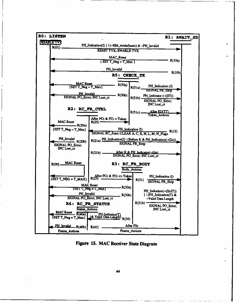
RO: LIS1TUN Ri: AWAITSD
VINB~bTYXPHjndication(I) I I (-HM-~mode(basic) & -PH-InvalidR(O1) RESET TVX; ENABLE TYX
MAC-Reset RlaI SET T-eg = T.Max)Rla
PH-Invalid R(lOb)
MASE TR.ese = T..ax)R(1a PH-Indication (1)I ST 7.Ne = ý_Mx) (51) bfUNAL i'.~rx p
SINLPH~r InCalid tc R(50b) PHjIndicator (-(=))SIGNL FErrr. NC Lsk~t R(1b)SIGNAL FOEITfr,
R2: - C-FR,.CTRLR(5lc) - ferlToken..Actions
'SE T-~g= TMax 4IGNAL RC...Start; CLEAR A, C, E, H, L, M, NJ1lagsR(2
PH~vldR(20b) R(21 a) PHJndicatioii(1) I (Before K & PHjndication(-(Iln)) m
SIGNAL FCLError; INC Losct-p
R(OO) MAC Reset R3: RC_-FR_-BODYBody-Action
mSa TJE ~X Cer FCr & FCr <> Token PH-Indication (I)_MA ) R( R(31) SIGNAL FR...SUpMAC Reset
I u ýpg= 1'MxI R(30a) PHj1ndcafion(-(EhnI))PH-Jnvalid R(30b) I I (PH-Indication(T) &
SIGNAL FQ-Error, INC LosLct-R3b -Valid Data Length ORd: RCrR,_STATUS R(1)SIGNAL ROLEnrrn.
StaW...Actions INC LosLctMAC ReadtR4a jpiao~
-SET TýNeg I JaL & V uft&IA UIR(4
hX R (40Ob) R(41) AfteiFSrPrame..Actions Frame-.Actions
Figure 15. MAC Receiver State Diagram
44
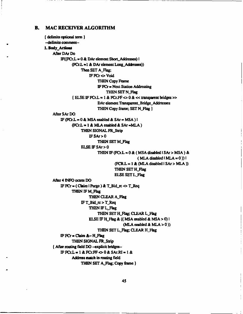
B. MAC RECEIVER ALGORITHM
(delimits optional tam)-delimits comment-1. BodWyAcdom
After DAr DoIF((rJ•L = 0 & DAr clement Short.Addrsses) I
(FCr.L -1 & DAr element LongAddreses))Then SET A-Flag;
IF FCr <> VoidTHEN Copy FrameIF Fr = Next Station Addressing
THEN SET NFlJag{ELSE IF FCr.L = 1 & FCr.FF o0& << transparent bridges >>
DAr element TranmntrBridgeAddrtessesTHEN Copy frame; SET N_Flag}
After SAr DOIF (FKr.L = 0 & MSA enabled & SAr = MSA) I
(FCr.L - I & MLA enabled & SAt =MLA)THEN SIGNAL FR_-Stip
IFSAr>0THEN SET MFlAg
ELSE IF SAr > 0THEN IF (FCr.L = 0 & (MSA disabled I SAr > MSA)&
(MLA disabled I MLA =0)) I(FCR.L 1 & (MLA disabled I SAr > MLA))THEN SET H_FlagELSE SET LYlag
After 4 IN octets DOIF FCr = (Claim I Purge) & TBidjc o TReq
THEN IF MFlagTHEN CLEAR A_.Flag
IF TBid_rc > T._ReqTHEN IF Llag
THEN SET Hjlag; CLEAR LjlagELSE IF HIFlag & ((MSA enabled & MSA > 0) I
(MLA enabled & MLA > 0))THEN SET L.Flag, CLEAR H_Flag
IF FCr Claim &- H.IagTHEN SIGNAL FRStrip
(After routing field DO -explicit bridges-IF FCr.L 1 & FCr.FF o 0 & SAr.RI = 1 &
Address match in routing fieldTHEN SET A.Fag; Copy frame)
45
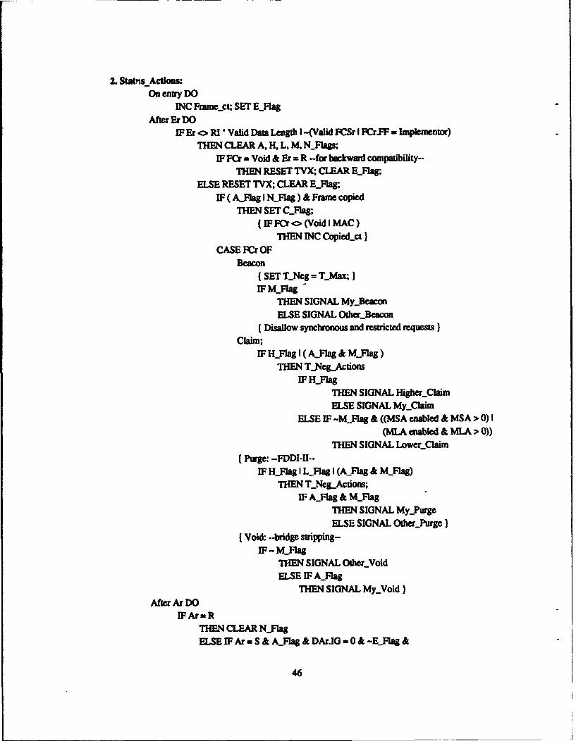
2. Statpis Acti6m
On entry DOINC Frame.ct; SET EFlag
After Er DO
IF Er <> RI' Valid Data Length I -(Valid FCSr I FCr.FF = Implementor)
THEN CLEAR A, H, L, M, NFlags;IF FCr = Void & Er = R -for backward compatibility-
THEN RESET TVX; CLEAR EFlag;ELSE RESET TVX; CLEAR EFlag;
IF ( &.Flag I NyFlag) & Frame copiedTHEN SET C-lag;
(IFFCr <> (Void I MAC)
THEN INC Copiedrt)
CASE FCr OFBeacon
( SET TNeg = T7_Max;}IF MFlag
THEN SIGNAL My-Beacon
ELSE SIGNAL Other-Beacon(Disallow synchronous and restricted requests}
Claim;
IF HFlag I (A_Flag & M_Flag)THEN T_NegActions
IF HFlagTHEN SIGNAL IHigherClaimELSE SIGNAL MyjClaim
ELSE IF-MFlag & ((MSA enabled & MSA > 0) I
(MLA enabled & MLA > 0))
THEN SIGNAL LowerClaim
(Purge: -FDDI-II--
IF HFlag I LFag I (&Flag & MjlAg)
THEN T._Neg_Actions;IF AFlag & MFlag
THEN SIGNAL My_Purge
ELSE SIGNAL Other-Purge}
(Void: --bridge stripping-
IF - M_.lagTHEN SIGNAL OtherYoidELSE IF A_Flag
THEN SIGNAL MyYoid}
After Ar DO
IFAr=RTHEN CLEAR NFlag
ELSE IFAr = S & A-Flag & DAr.IG= 0 & -EFlag &
46
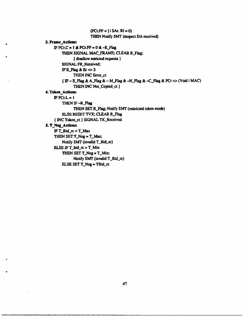
(FCr.FF =) I SAr. RI = 0)THEN Notify SMT (suspect DA received)
3. Frame Actions:IF FCr.C = I & FCr.FF = 0 & -EFlag
THEN SIGNAL MAC-FRAME; CLEAR RFlag;( disallow retricted requests)
SIGNAL FRReceived;FEFlag&EroS
THEN INC Errorsct
(IF - EFlag & AFlag & - MFlag & -NFlag & -CFlag & FCr <> (Void I MAC)
THEN INC NoLCopiedsct)4. Token Actions:
IF FCr.L = ITHEN IF -,RFag
THEN SET R_Flag; Notify SMT (restricted token mode)
ELSE RESET TVX; CLEAR RFlag(INC Tokenrct ) SIGNAL TK Received
3. TNegActions:IFT Bid rc < TMax
THEN SET TNeg = TMax;
Notify SMT (invalid TBid-rc)
ELSE IF T_bid.rc > TMin
THEN SET TNeg = TMin;Notify SMT (invalid T7_Bid~rc)
ELSE SET TNeg = TBid.rc
47
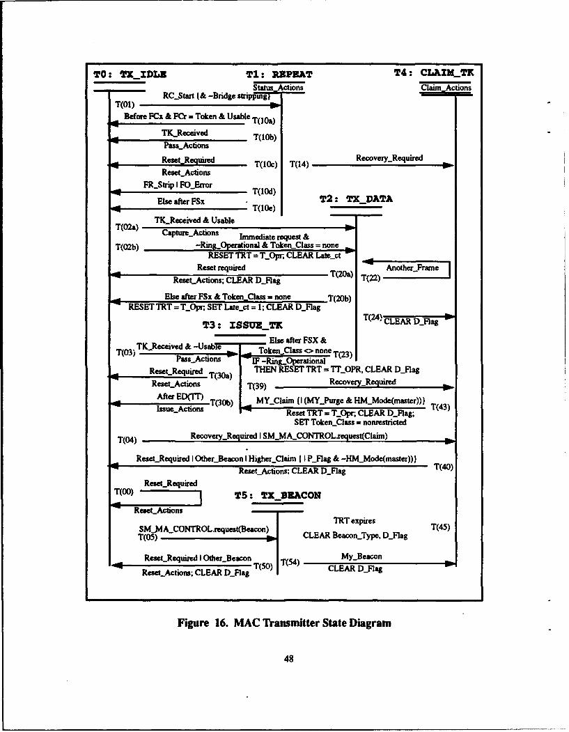
TO: TX_IDLE T1: REPEAT T4: CLAZIMT
Stwatus. Acions Clai AtonsRC-Start I& -Bridge strippingI
T(O1) -wBefore FCx & FCr = Token & Usable T(loa)
TKReceived T(I0b)Passý_Actions
ReseLR qinied T(1k) T(14) Recovery-Required
ReseLActions
SbiFQ~rorT(10d) T2: TXDATAElse after FSx_____
T(02&) Capture...Actions Imeit reus & -No
T(02b) -Ring-peational & Token..Class = none
Else after FSx & Token Class = none -T(20b)RESET TRT = T...Opr, SET Late-pt = 1; CLEAR D.Ylag
T3: ISSUETI T(24) CLEAR D.Ylag
TK...Received & -Usa e Else after FSX &T(03) s- Token..Class 0> none T(23)
Pass...Actions -IF -Ring-OperationalRestRquiedT(3a TEN RESET TRT = TrOPR, CLEAR D..Flag
Reset..Actions T() Recovery-Required
After ED(TI'IssueActions T(30b) Lý.My-.Claim I I (MY-Purge &- HM-Mode(master)))T43
Reset TRT = T...Opr; CLEAR D...Elag; T(3SET Token_Class = nonrestricted
T(04) RecoveryRequired I SMMA .CONTROL~request(Claim)
ResetLRequired I Otherý_Beacon I Higher...Clairn I I Pý-Rag & -HNC-Mode(master)))ReseLActions; CLEAR D..Ylag .(40)
t T(O) eoeuie TS: TX_8EACONReset-Actions
SM-MIA-.CONTROLireuest(Beacon) TRT expires T(45)T(05) - CLEAR BeaconjType, Dý_lag
'4 ReseLRequired I Other._Beacon T5)My-.Beacon '
Reset..Actions; CLEAR DjFlag T(50) T4) CLEAR DL~lag
Figure 16. MAC Transmitter State Diagram
48

C. MAC TRANSMITTER ALGORITHM
(deinmits optional term)--delimits comment-1. BodyActions
Before Rx DOF EYlJag
THEN SET Ex = SELSE SET Ex = R
Before Ax DOIF AjlW Ar=S
THEN SET Ax = SELSE F Ar = R
THEN SET Ax= R(ELSE SET Ax = T)
Before Cx DOF (Clag &-NFYag) I (Cr = S (&-Alag & Aro S))
THEN SET Cx = SELSE IFCr= R ( I (AFlaf& Ar -R))
THEN SETCx = R(ELSE SET Cx = T)
2. Usable-TokenRing-.Operational &(((Synchronous request & Synchronous Allowed) I)
(Asynchronous request & Requested token class = FCr.L &Late.ct = 0{& (Nonpiority request I TRT < Tri[Rcquest priority] ) }(& ( Nonrestricted request I
(Restricted allowed &(B_Flag I Requested token class = restricted)))))
3. PamsActionsIF Ring.Operational
THEN IF Late.ct = 0THEN RESET TRT = 7rOprELSE CLEAR Latesct
ELSE SET TOpr = T7Neg, RESET TRT = TOpr; SET Latest =1;SET Ring.Operational
IF FCr.L = ITHEN ( CLEAR B..Fag;}
SET TokenClas = nonrestrictedELSE [ SET B.Flag;)
(Stop bridge stripping)4. Capture_.Actions:
DISABLE THT;
49
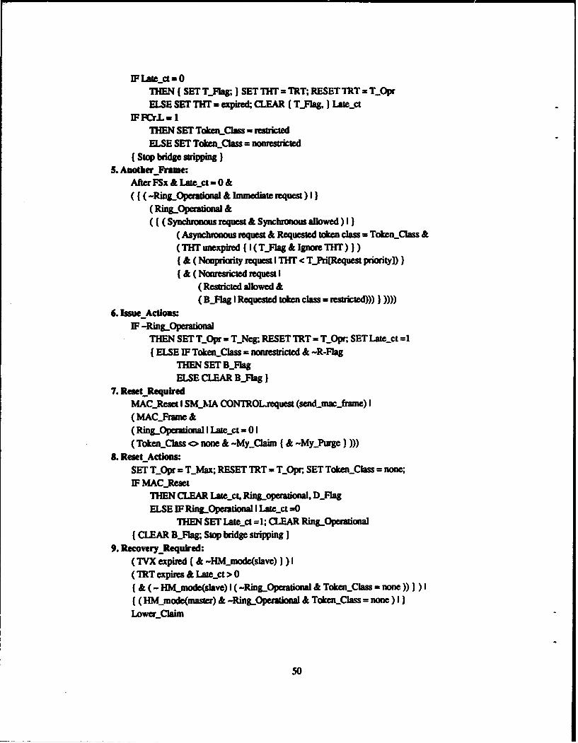
F Late..ct. =OTHEN ( SET Tjlag; ) SET TilT = ThT;, RESET TRT 7 T.OprELSE SET TIT m expired, CLEAR ( TY~ag& ) Lawest
IF ~r.L -1ITHEN SET TokenLCiass - restrictedELSE SET Token_,Clas = nonrestricted
(Stop bridge stripping)5. Another Frauze:
After FSx &Late..ct =O0&((-Ring-Operationa1 & Immediate request) I)
(Ring-Operational &((Synchronous request & Synchronous allowed) I)
( Asynchronous request & Requested token class =Tdken-Ciass &(THT unexpired ( I (Tj-ag &Ignore THT) ))(& ( Nonpriority request I THT < TPri[Request priority]))(& ( Nonesiricted request I
( Restricted allowed &(B-FlAg I Requested token class - restricted))) )))
6. Issue Actions:IF -Ring-Operational
THEN SET T...Opr - TýNeg; RESET TRT - T...Opr; SET Latesct =1(ELSE IF Taken-Class = nonrestricted & -R-Flag
THEN SET BjlagELSE CLEAR BjFlag)
7. Reset _RequiredMAC-Reset I SM..MA CONTROLrequest (send nac-.frame) I( MAC-rune &(Ring_.Opezatianal I Latesct =0 1(Token..Clms <> none. & -MyClaim (&-My-Purge) )
L. Reset Actions:SET T....pr = TjvMax; RESET TRT = T_0pr, SET TokeaLClass =none
EF MAC..ReseTHEN CLEAR Late..ct, Ring-operational, Dj~lagELSE EF Ring..Opemtional I Latest =0
THEN SET Lates-t = 1; CLEAR Ring-Pperational(CLEAR BjFlag; Stop bridge. stripping )
9. RecoveryRequired:(TVX expired ( & -Hjniode(slave) ) ) I(TRT expires & Latept > 0(& (- HM-node(slave) I (-Ring-Operational & TokenSlass - none))) )I((HM-node(mnaster) & -RinL-Operational & Token-Class = none) I)
Lower-claini
50
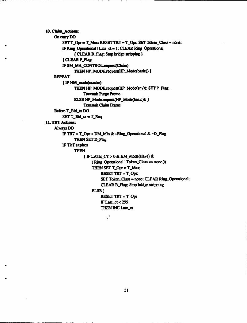
10. CWi Acdommon entryDO
SET T..Opr - Tjdax RESET TRT - T-OV; SET TokeiLCla~s none;IF Ring.Operaitoal I Lazect .-1; CLEAR Ring-Opetauuonal
(CLEAR B..Flag; Stop bridge strippifg)* (CLEAR P-Flag;
IF SMMACONTROLjrequest(Claim)
REPE T EN HP-MODErequestWH..Mode(basi)))
(IF HM-mode(nmoau)THEN HP-.MODE~reques*(HW.Mode(any)); SET Pý-lag;
Transmrit Purge FrameELSE lip...MdefrequestW(hP..ode(basic));)
Tvamnt Clam FrameBefore T.Bidjtx Do
SET T..Bidjtx = T-Req11. TRT Actlou
Always DOIF TRT > T-Opr + DM-AfD & -Ring Operatonal & -D-Jqag
THEN SET DjlagIF TRTexpires
THEN(IF LATE-.Cr > 0 & HKMjode(slave) &
(Ring-Opemfioal I TokenClas <> none))THEN SET T...Opr = Tjviax;
RESET TRT = TOpr;SET TokenClass = none CLEAR RingOperationaI;CLEAR BjIag; Stop bridge stripping
ELSE)RESET TRT = T_0prIF Late-pt < 255THEN INC Lawcci
51

APPENDIX B: DATA ENCRYPTION AND NETWORKS
A. OVERVIEW OF CRYPTOGRAPHY
Traditionally, security in computer networks has been facilitated through data
encryption/decryption.6 Advances in breaking ciphers coupled with faster more advanced
computers to employ these methods, raise questions about the ability of traditional
cryptographic techniques to provide a high degree of security. Furthermore, in order to
make these techniques more trusted they often become more complex. As cryptanalysis
becomes more sophisticated so must encryption techniques. This often leads to slower less
reliable systems which may be unacceptable in a real time environment requiring high data
rates rapid response times. Several standards for data encryption are in use with the Data
Encryption Standard (DES) probably being best known.
Encryption is a process of encoding a message so that the meaning is not readily
apparent to an unintended observer, decryption is the process of transforming the original
message back into original form. The original message is called plaintext while the
encrypted message is referred to as cipher text.
Ciphertext:. C = E(P)Plaintext: P = D(C)
We will denote plaintext as P and ciphertext as C. The transformation between
plaintext and ciphertext is accomplished using some encryption function denoted as E, and
a reverse decryption function D. Many algorithms employ a key K with the ciphertext
dependent on both the original plaintext message and the key value.
In general, certain principles should be considered when choosing a cipher for a
specific application. The overhead associated with encryption and decryption should be
consistent with the level of security necessary. The enciphering algorithm and key
52

management technique should be free from complexity. [Shan 49] However, the algorithm
need not be simple as long as the time complexity is tolerable for the application. Errors in
ciphering should not propagate and cause further corruption of the message. The size of the
ciphertext message should never exceed the original plaintext message.
Optioal Key
Plaintext Ciphemtext Original Plaintext
Figure 17. Basic Crypto System
Some encryption techniques use a key K, which determines the ciphertext. Data is
still considered protected with a public algorithm as long as the key is secret. However,
keys are generally shorter than the plaintext to be encrypted and thus are more susceptible
to cryptanalysis given enough ciphertext to analyze.
A session key is designed to be changed after a prescribed time has passed or certain
amount of data has been transmitted. By changing keys periodically, an intruder has more
difficulty accumulating enough data to determine the key. Even if the key is discovered it
will be changed again when the session has expired. The biggest problem with session keys
is providing an efficient and secure method of distribution.
A network key server is a process that distributes keys to users on request. The key
server shares a unique key with each station. If station A wants to communicate with station
B, A must call the key server saying a session key is desired between stations A and B. The
key server then generates a new key which it sends to A and B. A and B both decrypt the
session key KS, and transact their session using KS. This method can be used to provide
end-to-end encryption without the massive number of keys normally needed. Each station
53

requires only a single key to communicate with the key server. The amount of ciphertext
between the central key server and each station is small enough o make cryptanalysis of the
master keys difficult. The unique key shared between each station and key server facilitates
peer to peer authentication between stations A and B.
1. Stream Ciphers
The basic bit stream cipher used for network encryption is a form of substitution.
This method usually incorporates a cipher key which is used as a seed to a pseudo-random
number generator (PRG). The output bit stream from the PRG is referred to as the
Initialization Vector (IV) and is combined by modulo 2 addition with plaintext to produce
the ciphertext. A similar approach is the bit stream cipher with cipher feedback where
ciphertext is returned to the PRG as a parameter. A third technique is to use plaintext as
feedback to the PRG. A variation of the previous techniques would be to delete the PRG
and use a continuous random bitstream key. This method provides a theoretically
unbreakable one time cipher, provided the key stream is used only once. This means given
a plaintext message, it would never be encrypted the same way twice. [Muft 91]
3. Opdonal Feedback PG2. Optional Feedback
Pii+nt .• IV + Plaintext
Figure 18. Stream Cipher Variations
The simple bit stream cipher is easy to perform and does not require a complicated
algorithm for decryption. The complexity of the cipher corresponds to direct translation
with an order of magnitude of n. In bit stream ciphers, individual symbols are encrypted
54
independent of the original plaintext symbols. This means that the only way to build a
reversible crypto function is through modulo two addition. In terms of complexity, the
speed to transform the plaintext into ciphertext is only dependent on the algorithm itself and
not the time it takes to receive more plaintext. Errors are not propagated because each
symbol is encrypted as a separate entity, and a single error in the encoding process will
cause an error in only a single character. With no error propagation it is often possible for
the receiving station to determine the correct character in error.
Bitwise enciphering does expose several disadvantages. A cryptanalyst could
more easily analyze the characteristics of individual symbols in the ciphertext and attempt
to break the encryption using digram analysis, distribution counts, index of coincidence or
several other tools. Once a code is broken a malicious intruder could destroy the integrity
of passing messages by splicing together pieces of previous messages and transmitting a
spurious new message which may look authentic.
2. Block Ciphers
The second basic method of encryption called a block cipher is based on
transposing the message across the cipher text. The purpose of the transposition is to diffuse
the message by breaking up established patterns. A simple block cipher might involve
transposing columns into rows. The plaintext columns are divided into blocks of a defined
length and then reassembled by arranging the blocks into rows. Cryptanalysis methods for
block ciphers are not as scientific as for substitution ciphers. This is particularity true when
multiple transpositions have been performed. The cryptanalyst is forced to make more
"guesses" at probable plaintext to obtain clues about the transposition. It is often necessary
to perform a letter frequency distribution to determine if a block cipher has even been
applied. Attacks on block ciphers are usually based on common letter pairs and triplets
called digrams and trigrams, which appear frequently in plaintext. A cryptanalyst may use
the knowledge of these patterns to match plaintext characters which have been separated in
the transposition. Once the plaintext and ciphertext character position relationship is
55
determined, the algorithm is basically broken. Another distinct disadvantage of
transposition ciphers is that the message cannot be decrypted until all of the message is
read. Although the time complexity of the algorithm is proportional to the length of the
message, so is the delay associated with reading the entire message before beginning
deciphering. These algorithms also incur added storage requirements. These considerations
make transposition algorithms less appropriate for long messages or when a rapid response
time is required. [Carr 90]
3. Key Systems
a. Conventional Key Encryption
Conventional key encryptions systems are based on the sharing of a single
secret key by all authorized parties. This type of key system utilizes the same key for both
the encryption and decryption functions. Consequently, communicating stations can each
send and receive messages using the same key. For this reason conventional secret key
systems are referred to as symmetric.
Messages encrypted using a conventional key system are inherently
authenticated provided that the secrecy of the key is trusted. In other words an encrypted
message transmitted by A using A 's key must have been transmitted by A since only A has
access to the key. One problem is that if each transmitting/receiving station pair is to share
a unique key, then the total number of keys required increases with the square of the
number of stations requiring keys.
Keys must be distributed in a secure manner since they allow access to all
information encrypted under them. One approach to the distribution problem is to use a key
server that distributes keys to users on request. The key server shares a unique master key
with each station. When two stations wish to communicate confidentially the server
delivers a session key to each station encrypted under their respective master keys. Figure
17. depicts the protocol for central key server operation. By using a key server, each station
only needs to maintain a single master key with the server and the session key in use.
56

However, establishing new session keys with every new communication may incur an
unacceptable overhead for applications which require rapid response times. Numerous keys
being distributed could also occupy considerable bandwidth resulting in less efficient
system performance.
5. A communicuates with B using KtB
1. Arequests asession key 4. Asends KSto Bunder KtB
3. S mends two copies of KS to A. one under KtA one under Kts
So 2. Seaver produces Ks
Figure 19. Key Server Distributing Session Keys
b. Public Key Systems
Public key systems are based on the principle of providing each user with
two keys: a private key and a public key. The two keys operate as inverses with the public
key used to perform a one way encryption and the secret key used to decrypt. In other words
a user can decrypt a message using a'private key that someone else encrypted using the
corresponding public key. An additional property is that the two key- .an be applied in
either order.
P = D(krivate, E(klublic, P)or
P - D(kublic, N(kprrvat., P)
57
With public keys, only two keys are needed per user for communication
capability with all other stations. However, peer-to-peer authentication is not inherent since
every station may have access to all public keys. Authentication can be provided in a public
key system using a double encryption. [Need 78] A message encrypted by transmitting
station A using A's private key then encrypted again using receiving station B's public key,
will be both secret and authentic. Authenticity is provided by A's private key which only
A can use to encrypt. Likewise secrecy is provided by B's public key which only B can
decrypt with the secret key.
Public key systems are typically based on much more complex problems
than single key systems. This complexity usually translates to slower encryption/
decryption speeds. Slower speeds coupled with the requirement for double encryption to
support peer-to-peer authentication and privacy make public keys less attractive for
applications requiring rapid response times.
With the exception of the Rivest-Shamir-Adelman (RSA) encryption, most
of the public key algorithms seen to date have been shown to exhibit substantial
weaknesses. A number of public key encryption schemes have recently been introduced but
have not been in existence long enough to have undergone the intense scrutiny by
cryptanalysis professionals needed to instill a high confidence level.
Public systems require each station to maintain a private and a public key.
However, for one stations to use another stations public key, it must either store the key or
request the key from another station. The primary difference between public and private
key system storage and access requirements is that public keys may be stored in public
memory, where private keys must be kept secret. The actual space and time requirements
are essentially the same.
58

B. DATA ENCRYPTION STANDARD (DES)
The Data Encryption Standard (DES) is a product cipher which was developed by
IBM. The encryption algorithm has since been implemented in hardware making it fast and
cheap. In contrast to earlier cryptographic techniques with long keys, the DES relies on a
56 bit key with a 19 stage complex convoluted algorithm using both transposition and
substitution. The DES is capable of operating in a block as well as bit stream cipher mode.
The block mode is subject to the limits discussed and is not used in our method.
C. RIVEST-SHAMIR-ADELMAN (RSA) ENCRYPTION
The RSA algorithm is based on the hard problem of determining the prime factors of
a large target number. Unlike the public key system described previously, RSA does not
distinguish between public and private keys. The encryption and decryption keys are
referred to as e and d respectively. The encryption algorithm uses exponentiation
performed mod n against the plaintext block (Pe mod n). This makes it very difficult to
factor Pe and discover the plaintext. The decrypting key is chosen such that (PI)d mod n =
P. Therefore, the decryption does not require Pe to be factored.
Ciphertext - Plaintext* mod n
Plaintext - Ciphertextd mod n
Despite extensive study by cryptanalysts, no serious flaws have been discovered in
the RSA algorithm. However, the fastest known algorithm for the RSA factorization is
exponential in time. In addition, the public key nature of RSA necessitates a double
encryption to provide peer-to-peer authentication. Although the RSA is available in
hardware, the complexity of the algorithm limits the usefulness for real time applications.
The RSA is also a patented device.
59
D. LINK VS. END TO END ENCRYPTION
Encryption in networks is applied either between two hosts or between two
applications. These two methods are called link encryption and end-to-end encryption.
With link encryption data is encrypted at layers 1 or 2 in the OSI model just prior to being
placed on the physical medium. The message is protected as it passes between two nodes
but is actually decrypted and then re-encrypted at each host. In other words, the message is
in plain text inside the host. Link encryption is especially vulnerable when messages must
pass through one or more additional hosts between sender and receiver. End-to-end
encryption security is provided from the transmitting station to the receiving station. As the
message passes through each node it remains encrypted. End-to end encryption is usually
performed at levels 6 or 7 of the OSI model. [Voyd 85]
60

LIST OF REFERENCES
[Adam 92] Adam, J.A., "Data Security," IEEE Spectrum, August 1992, pp. 19-44.
[Carr 90] Carrol, John M., "Do-it-Yourself Cryptography," Computers and Security,September 1990, pp. 613-619.
[Coom 91] Coomaraswamy, G., Kumar, S.P. and Marhic, M.E., "Fiber-Optic LAN/MAN Systems to Support Confidential Communication," Computers andSecurity, v. 10, 1991, pp. 756-776.
[Ehrs 78] Ehrsam, W. "A Cryptographic Key Management Scheme for Implementingthe Data Encryption Standard." IBM Systems Journal, v. 17, no. 2, 1978, pp.56-61.
[FDDI 87] FDDI Token Ring Media Access Control (MAC), ANSI Standard X#.139-1987, REV 10.
[FDDI 91] FDDI Media Access Control (MAC R), Rev 4.0, 1990.
[Hall 91] Halloran, F. and others, "An FDDI Network for Tactical Applications,"IEEE LCS, February 1991, pp. 29-35.
[Koch 91] Kochanski, R. J., Paige, J.L., "SAFENET: Standard and its Application,"IEEE LCS, February 1991, pp. 46-5 1.
[Lund 90] Lundy, G.M., "Improving Throughput in the FDDI Token Ring Network,"Naval Postgraduate School 1990.
[Muft 91] Muftic, S., Security Mechanisms For Computer Networks West Sussex,England 1989.
[Need 78] Needham, R.M. and Schroeder, M.D., "Using Encryption for Authenticationin Large Networks of Computers," Communications of the ACM, vol. 21,no. 12, pp. 993-999, December 1978.
[Pfle 89] Pfleeger, C. P., Security In Computing, Prentice Hall Inc., New Jersey, 1989.
[Ross 89] Ross, F. E., "An Overview of FDDI: The Fiber Distributed Data Interface,"IEEE Journal on Selected Areas in Communications, September 1989.
[Schn 85] Schnackenberg, D.D., Development of a Multilevel Secure Local AreaNetwork, Proceedings, of the 8th National Computer Security Conference,1985, pp. 97-104.
[Shan 49] Shannon, C. "Communication Theory of Secrecy Systems," Bell SystemsTechnical Journal, v. 28 October, 1949, pp. 656-715.
61
[Stal 91] Stallings, W., Data and Computer Communications, 3d. ed., MacmillanPublishing Company, 1991.
[Tard 85] Tardo, J., "Standardizing Cryptographic Services at OSI Higher Layers,"IEEE Communcations Magazine, July 1985, pp. 25-29.
[Voyd 85] Voydock, V., Kent, S.,"Security in High-Level Network Protocols", IEEECommunications Magazine., July 1985, pp. 12-24.
[Stoll 90] Stoll, C., The Cuckoo's Egg, POCKET BOOKS, New York 1990.
62

BIBLIOGRAPHY
Abrams, M.D., Podell, H.J., Tutorial Computer andNetwork Security, IEEE Computer Society Press, 1987.
Chorafas, D. N., Handbook of Data Communications andComputer Networks, TAB BOOKS, 1991.
Coomaraswamy, G., Kumar, S.P.R. and Marhic, M.E.,"Fiber-Optic Configurations Supporting Confidentiality inPassive DQDB Systems," Proceedings IEEE INFOCOM'91, v. 2, April, 1991, pp. 901-910.
Hoffman, L.J., Modern Methods for Security and Privacy,Prentice Hall, 1977.
Johnson, D.B., and others, "Common CryptographicArchitecture Cryptographic Application ProgrammingInterface," IBM Systems Journal, v. 30, no. 2, 1991.
Keck, D.B. "Fundamentals of Optical Waveguide Fibers,"IEEE Communications Magazine, v. 23, no. 5, May 1985.
Lundy, G.M., Akyildz, I.F., "Specification and Analysis ofthe FDDI MAC Protocol Using Systems of CommunicatingMachines," Naval Postgraduate School, Monterey, CA.,September 6, 1991.
Marhic, M.E., Chang, Y.L., "Pulse Coding and CoherentDecoding in Fibre-Optic Ladder Networks," ElectronicsLetters, v. 25, no. 22, October 26, 1989.
Matyas, S.M., Le, A.V. and Abraham, D.G., "A KeyManagement Scheme Based on Control Vectors," IBMSystems Journal, v. 30, no. 2
Muftic, S., "Transaction Protection by Antennas,"Computers and Security, September, 1990, pp. 245-255.
63

Preneel, B., and others, "Cryptanalysis of a FastCryptographic Checksum Algorithm," Computers andSecurity, September, 1990, pp. 257-261.
Schoemaker, S., Computer Networks and Simulation III,Elsevier Science Publishers, 1986.
Tannenbaum, A. S., Computer Networks, 2d ed., PrenticeHall, 1988.
Tassel, D.V., "Computer Network CryptographyEngineering," National Computer Conference InformationTechnology Series, v. 3, AFIPS PRESS, 1978, pp. 197-202.
U.S. Department of Commerce, National Bureau ofStandards, Design Alternatives for Computer NetworkSecurity, Government Printing Office, Washington D.C.,1978.
64

INITIAL DISTRIBUTION LIST
1. Defense Technical Information Center 2Cameron Station
* Alexandria, VA 22304-6145
2. Dudley Knox Library 2Code 52Naval Postgraduate SchoolMonterey, CA 93943-5002
3. Chairman, Code CS 2Code CS, Department of Computer ScienceNaval Postgraduate SchoolMonterey, CA 93943-5100
4. Dr. G.M. LundyCode CS/Ln, Department of Computer ScienceNaval Postgraduate SchoolMonterey, CA 93943-5100
5. Roger StempCode CS/Sp, Department of Computer ScienceNaval Postgraduate SchoolMonterey, CA 93943-5100
6. Lieutenant Benjamin E. Jones7788 Alspice Circle EastJacksonville, FL 32244
7. Curricular OfficeCode 37, Department of Computer ScienceNaval Postgraduate SchoolMonterey, CA 93943-5100
8. CommanderNaval Computer and Telcommunications Command4401 Massachusetts Ave., N.W.Washington, D.C. 20370-5000
9. CDR Debbie CampbellNational Computer Security Center NSA / C81 / APSXI9800 Savage Rd.,Ft. Meade, MD 20755-6000
10. Naval Information Systems Managenment CenterBuilding 166,Washington, D.C. 20374-5070
65

11. SPAWARCode 2241Crystal City 5CPK, 700Washington, D.C. 20363-5100
66