naval postgraduate school - defense technical … · naval postgraduate school code 37 naval...
TRANSCRIPT

NAVAL POSTGRADUATE SCHOOLMonterey, California
DESIGN AND IMPLEMENTATION OF A DENTALINFORM[ATION RETRIEVAL SYSTEM (DIRS)
by
Roger Kirouac
and
Brad R. Triebwasser
March 1990
Thesis Advisor: Robert L. Knight
Approved for public release; distribution is unlimited
r
_%'-U
0i

UNCLASSIFIEDSECURITY CLASSIFICATION OF THIS PAGE
REPORT DOCUMENTATION PAGE
la. REPORT SECURITY CLASSIFICATION lb RESTRICTIVE MARKINGS
UNCLASSIFIED2a. SECURITY CLASSIFICATION AUTHORITY 3. DISTRIBUTION/AVAILABILITY OF REPORT
Approved for public release;2b. DECLASSIFICATION/DOWNGRADING SCHEDULE distribution is unlimited
4. PERFORMING ORGANIZATION REPORT NUMBER(S) 5. MONITORING ORGANIZATION REPORT NUMBER(S)
6a. NAME OF PERFORMING ORGANIZATION 6b. OFFICE SYMBOL 7a. NAME OF MONITORING ORGANIZATION
(If applicable)
Naval Postgraduate School Code 37 Naval Postgraduate School
6c. ADDRESS (City, State, and ZIP Code) 7b. ADDRESS (City, State, and ZIP Code)
Monterey, California 93943-5000 Monterey, California 93943-5000
Ba. NAME OF FUNDING/SPONSORING 8b. OFFICE SYMBOL 9. PROCUREMENT INSTRUMENT IDENTIFICATION NUMSERORGANIZATION (If applicable) a
8c. ADDRESS (City, State, and ZIP Code) 10 SOURCE OF FUNDING NUMBERS
PROGRAM PROJECT TASK IWORK UNITELEMENT NO. NO. NO IACCESSION NO.
11. TITLE (Include Security Classification)
DESIGN AND IMPLEMENTATION OF A DENTAL INFORMATION RETRIEVAL SYSTEM (DIRS)
12. PERSONAL AUTHOR(S)
Kirouac, Roger and Triebwasser, Brad R.13a. TYPE OF REPORT 13b TIME COVERED 114. DATE OF REPORT (Year, Month, Day) 115 PAGE COUNT
Master's Thesis IFROM TO 1990, March I 14516 SUPPLEMENTARY NOTATION
The views expressed in this thesis are those of the authors and do not reflect the official
policy or position of the Depar-e-tn of Defense or the U.S. C-overnment.17. COSA.I CODES 18 SUBJECT TERMS (Continue on reverse if necessary and identifI SUJEC TEMS (ontnueon evere i neessay ad ient by, bloik number)
FIELD GROUP - SUB-GROUP Design and Implementation of a Dental ntormation
Retrieval System (DIRS); Database Project
19 ABSTRACT (Continue on reverse if necessary and identify by block number)
All Naval dental treatment facilities (DTF) worldwide are required to sub-
mit monthly reports containing detailed records of treatments provided and
overall dental readiness to COMNAVMEDCOM, in Washington, D.C. These reporting
requirements are standardized to meet not only the reouirements of the Navy,
but also as input to the DOD mandated Medical Expense and Performance System
(MEPRS). At many commands, this data collection storage and reporting effort
is currently performed manually, adding unnecessary additional administrative
burden.
This thesis develops a computerized database system providing increased
accuracy and productivity, and capable of meeting the NAVMIED reporting tequire-
ments. The Dental Information Retrieval System (DIRS) developed will record
all treatment-- provided for each beneficiary category described in NAVMED-
COMINST 6600.lB, and will facilitate internal and external daily, weekly,
20 DISTRIBUTION/AVAILABILITY OF ABSTRACT 21. ABSTRACT SECURITY CLASSIFICATION
UUNCLASSIFIEDUNLIMITED 0 SAME AS RPT 0 DTIC USERS Unclassified22a NAME OF RESPONSIBLE INDIVIDUAL 22b TELEPHONE (Include Area Code) zc OFFICE SYMBOL
LCDR Pobert L. Knight (408) 646-2771 Code 54Ft
DD FORM 1473, 84 MAR 83 APR edton may be used until exhausted Eiok, i Y CLASSIFICATION OF THIS PAGEAll other editions are obsolete 0 U.S. 06111-.1 P"1..2 Office 1111-4@1124.
UNCLASSIFIED

UNCLASSIFIEDSECURITY CLASSIFICATION OF TIS PA0E
#19 - ABSTRACT - (CONTINUED)
monthly and annual reporting requirements. An importantdesign consideration is providing the DIRS developed withthe requisite capabilities specified by the DTF's, withoutimposing additional hardware requirements.
NAVDENCLINIC Long Beach, Ca., is the sponsoringactivity for the DIRS, and will serve as the test sitefor system implementation. If the system is successful,Director of Dental Services, San Diego, Ca., has indicatedinterest in the system as a Navy-wide managerial tool.
ii UNCLASSILITlEDSECURITY CLASS;FICATIO . OF lm 5 PA3

Approved for public release; distribution is unlimited
Design and Implementation of aDental Information Retrieval System (DIRS)
by
Roger KirouacLieutenant, United States Navy
B.S., University of Colorado, 1985
and
Brad R. TriebwanerCaptain, United States Marine CorpsB.A., University of Washington, 1981
Submitted in partial fulfillment of therequirements for the degree of
MASTER OF SCIENCE IN INFORMATION SYSTEMS
from the
NAVAL POSTGRADUATE SCHOOLMarch 1990
Roger Kirouac Brad R. Triebwasser
Approved by: __ _ __ _ _ __ _ _
Robert L. Rnight, Thesis Advisor
-- agd-. Ke-cU eader
David R.'Whipple-_ChairmanDepartment of Administ-itive Sciences
iii

ABSTRACT
All Naval dental treatment facilities (DTF) worldwide are
required to submit monthly reports containing dental records
of treatments provided and overall dental readiness to COMNAV-
MEDCOM, in Washington, D.C. These reporting requirements are
standardized to meet not only the requirements of the Navy,
but also as input to the DOD mandated Medical Expense and Per-
formance System (MEPRS). At many commands, this data collec-
tion storage and reporting effort is currently performed
manually, adding unnecessary additional administrative burden.
This tiasis devtlops a computerized database system
providing increased accuracy and productivity, and capable of
meeting the NAVMED reporting requirements. The Dental Infor-
mation Retrieval System (DIRS) developed will record all
treatments provided for each beneficiary category described in
NAVMEDCOMINST 6600.1B, and will facilitate internal and
external daily, weekly, monthly and annual reporting require-
ments. An important design consideration is providing the
DIRS developed with the requisite capabilities specified by
the'DTF's, without imposing additional hardware requirements.
NAVDENCLINIC Long Beach, Ca., is the sponsoring activity
for the DIRS, and will serve as the test site for system
implementation. If the system is successful, Director of
iv

Dental Services, San Diego, Ca., has indicated interest in thesystem as a Navy-wide managerial tool.
I.
-- '---v

TABLE OF CONTENTS
I. INTRODUCTION-------------------------------------------- 1
A. BACKGROUND------------------------------------------1
B. STATEMENT OF PROBLEM------------------------------ 4
C. SCOPE------------------------------------------------6
D. METHODOLOGY-----------------------------------------7
E. FEASIBILITY-----------------------------------------8
II. USER REQUIREMENTS------------------------------------- 10
A. PRESENT SYSTEM-------------------------------------10
B. REQUIREMENTS DEFINITION--------------------------14
III. SYSTEM DESIGN------------------------------------------ 27
A. LOGICAL DATABASE DESIGN--------------------------27
B. APPLICATION DESIGN---------------------------------36
C. MENU HIERARCHY DESCRIPTIONS----------------------39
IV. SYSTEM IMPLEMENTATION--------------------------------- 56
A. INTRODUCTION-------------------------------------- 56
B. dBASE III PLUS-------------------------------------58
C. SOFTWARE DOCUMENTATION----------------------------61
D. REPORTS---------------------------------------------61
V. CONCLUSIONS AND RECOMMENDATIONS----------------------63
A. SUMMARY AND CONCLUSIONS---------------------------63
B. RECOMMENDATIONS AND FUTURE WORK----------------- 65
APPENDIX A: OBJECT DIAGRAMS---------------------------------66
APPENDIX B: OBJECT DEFINITIONS---------------------------- 68
vi

APPENDIX C: LOMAIN DEFINITIONS ----------------------- 71
APPENDIX D: DATA FLOW DIAGRAM ------------------------ 76
APPENDIX E: UPDATE, DISPLAY AND CONTROL MECHANISMS --- 79
APPENDIX F: RELATION DIAGRAM ------------------------- 98
APPENDIX G: LOGICAL MENU STRUCTURE ------------------- 99
APPENDIX H: SAMPLE REPORTS i---------------------------100
APPENDIX I: NAVMED FORM 6600/11 ---------------------- 108
APPENDIX J: NAVMED FORM 6600/8 Iii-----------------------1
APPENDIX K: DENTAL INFORMATION RETRIEVAL SYSTEM(DIRS) USER S MANUAL --------------------- 113
LIST OF REFERENCES ------------------------------------ 134
INITIAL DISTRIBUTION LIST ----------------------------- 135
vii

I. INTRODUCTION
A. BACKGROUND
Naval Medical Command (NAVMEDCOM), Washington, D.C., is
chartered to provide general and specialized health and dental
care for active duty members of the Navy and Marine Corps at
ships, posts, and stations worldwide. When available, this
service extends to other eligible beneficiaries; members of
other Federal Uniformed Services, retirees and their
dependents, and dependents of active duty personnel.
To meet requirements for internal and external budgeting,
performance, training and readiness reporting, NAVMEDCOM tasks
all activities providing dental care to submit Dental
Information Retrieval System (DIRS) reports as prescribed in
NAVMEDCOMTMST 660r) -. This ilstruction provides guidance for
submission of monthly reports from subordinate Dental
Treatment Facilities (DTF) or Regional Headquarters to
COMNAVMEDCOM in Washington D.C. Procedures for ieporting
dental readiness are explicitly specified in the instruction,
including outlines of treatment codes and the associated
composite time values required for producing mandated monthly
reports used as input to the Medical Expense and Performance
System (MEPRS). MEPRS is a Department of Defense (DOD)
mandated report that is prepared at NAVMEDCOM from input

provided by subordinate medical and dental commands in the
Department of the Navy (DON).
Commanding officers and heads of dental departments at all
activities providing dental care are responsible for
submission of NAVMED 6600/8, the DIRS monthly Treatment
Report. If personnel from more than one DTF are combined
under a single command, then the senior dental officer at the
headquarters level is responsible for compliance with the
NAVMEDCOMINST directives and for the accurate treatLnent totals
assigned to the corresponding provider.
The preface to NAVMEDCOMINST 6600.1B states:
The (COMNAVMEDCOM) DIRS is a computer-based collection andinformation processing system designed to collect data onthe treatment provided to all eligible beneficiaries. Theinformation provided by the DIRS will assist Dental Corpsmanagers at all levels in accomplishing accurate andrealistic planning for resource requirements, allocation,and use. [Ref. 1]
Submission of the NAVMED 6600/8 and other dental reports
follow thie dental command hierarchy depicted in Figure 1.1.
At NAVMEDCOM level, the DIRS is a computer-based system.
However, the DIRS Treatment Ronort (NAVMED 6600/8), the
requisite monthly feeder report from all DTF's, is a ten-pitch
optical character recognition (OCR) form that presently may
only be prepared manually. It is this mandated submission
format and data collection requirement that has created a need
for the development of computerized DIRS at the lower echelon
DTF's. Although some commands have proceeded with in-house
development of automated DIRS, none have been successful in
2

N &NPIPLBTP'R OLIIOSDT'
Figure 1.1 Organization Chart
providing adequately for data integrity issues such as
redundancy, consistency and concurrency. Most systems were
created by non-ADP personnel with little or no formal tzaining
in database design issues, hence much of the desired
functionality, especially in the areas of updates to the
database and supporting documentation, were inadequately
addressed or exhibited poor design.
The mandated monthly NAVMED 6600/8 report resulting from
either a manual or computerized DIRS is transcribed via OCR-A
capable typewriter, and the resulting original form is mailed
to COMNAVMEDCOM. Reports submitted for a given month are to
3

be received no later than the 15th day of the following month.
At NAVMEDCOM in Washington, D.C., these reports are entered
into the DIRS via OCR reader. Any failure in the ability of
the OCR reader to assimilate the correct data, caused by
ordinary and extraordinary events such as folds, staple holes,
stains, rips, ink too light, misaligned characters, etc.,
requires report resubmission by the corresponding DTF. The
weakness of such a system is obvious, and represents a major
bottleneck to the efficiency and success of the reporting
system.
B. STATEMENT OF PROBLEM
The problem with DIRS is twofold: The first problem is
that manual systems require assignment of a significant
collateral duty to a dental technician (DT) to gather, sort,
compute and report dental treatment information submitted by
each provider. Each individual treatment is assigned a
composite time or weighted point value. The time savings
offered by an automated system, would allow better use of the
DT assigned to this task in more critical duties related to
actual patient care. The second problem is that existing
computerized DIRS applications are command dependent; lacking
standardization in quality and capabilities and tailored only
for a specific command. The presert computerized DIRS
application is also dependent on a particular database
package. For example, any update function must be achieved
via the specific DBMS used to develop the application program.
4

This dependency is costly in the sense that given a DIRS
system programmed using a commercial database package such as
ORACLE or INGRES, that specific package must first be
installed on the personal computer (PC) used for DIRS
reporting. The personnel operating such a system must be
familiar with the nuances and features of the particular
database package, which complicates the training on the
system.
A solution to these problems was hoped to be found in the
Dental Management Information System (DENMIS), a proposed
tri-service system, which had its first module (patient
appointment module) tested last year at Headquarters NDC Long
Beach, Ca., with unsatisfactory results.
Further development effort on the DENMIS and on individual
modules such as DIRS was halted with the original contractor.
The DENMIS contract was relet through NARDAC, Washington,
D.C., with proposed testing at 27 sites in 1990. According
to the contract firm, the proposed DENMIS will require an
80386-based personal computer to function properly. This
particular specification tends to limit the utility of the
program developed, for some Dental Treatment Facilities,
especially small or deployed DTF's currently lack this
additional specified hardware requirement. Recent information
indicates that the contracted DENMIS system will not include
a DIRS module as a result of insufficient funding. [Ref. 2]
The current thesis work is not intended to replace DENMIS, but
5

to provide a quality DIRS module for NAVDENCLINIC Long Beach,
Ca., and the Director of Dental Services, San Diego, Ca.,
until possible future delivery of a contractor-developed DIRS.
The identified requirement for a computerized DIRS coupled
with the uncertain future of DENMIS, have generated renewed
interest in the development of a proposed flexible PC-based
DIRS system that will aid lower echelon DTF's in meeting the
stringent reporting requirements mandated by COMNAVMEDCOM.
C. SCOPE
The proposed Dental Information Retrieval System (DIRS) is
intended to provide a stand-alone, compiled, non-command
dependent relational database system and associated
applications program. The system is necessary to support
administration, documentation and accounting of patient
treatment provided by dental officers and dental laboratory
technicians. The software system development life cycle
(SDLC) will be used to develop a working DIRS (to include:
system analysis, design, development, documentation in the
form of user's manual, implementation and training). Research
issues are listed below:
- Identification of user requirements.
- Examine present instructions or guidelines for DIRS.
- Determine if it is feasible to develop a DIRS's systemthat is not dependent on an external DBMS; i.e., dBASEIV, dBASE III PLUS, ORACLE or any other off-the-shelfDBMS.
6

- Determine if a DIRS's system can be developed that iscommand independent, i.e., Unit Identification and/orprovider(s) code not hardcoded in source code.
- Develop a system to support multiple clinics, yet accountfor each DTF separately.
- Execute critical file back-up without requiring access toan external DBMS.
- Organize, sort, and index files without access to an
external DBMS.
The goal of this development effort is an imbedded DBMS in
the compiled DIRS application that can be used on any IBM PC
compatible system with a minimum 20 megabyte hard disk
commonly found throughout the U.S. Navy dental community.
Success with this project would reduce unnecessary
off-the-shelf database purchases, reduce many long hours of
manual data collection and manipulation to produce mandated
reports. Automation will improve accountability of dental
productivity, and will provide better utilization of dental
personnel.
D. METHODOLOGY
Prior to development of a computerized DIRS, the current
system must be analyzed and the needs of system users
identified. A four-phase process of system analysis will be
followed: study, requirements definition, design and
implementation phase.
In the study phase, the relative characteristics,
capabilities and deficiencies of the current system are
examined and documented.
7

Specific objectives in gaining a thorough understanding of
the system are:
- Identify system users and others affected by the currentsystem.
- Identify deviations and deficiencies between goals,purpose, policies and objectives of the present system,and actual system performance.
- Identify functions of the current system that provideadequate support to the mission and users.
- Map the components of the present system, and analyze the
required interaction.
In requirements definition, the second phase of systems
analysis, the following two goals were identified:
- Identification of required objects and their structure.
- Identification of functional components for eachapplication with access to the database.
In design phase, the third phase of systems analysis, the
specific actions listed below must occur:
- Transformation of objects into a relational design.
- Developing the functional requirements into applicationdesign. This includes detailed formats for forms,reports, menus, and logic for programs.
Implementation is the actual transformation of relations,
and pseudo-code developed during design phase into files and
working applications. In this phase, actual coding, testing,
installation, and training of users will occur.
E. FEASIBILITY
1. Cost
The developmental cost of the Dental Information
Retrieval System is limited to the personal time and effort of
8

the thesis participants. Equipment needed for system
development is now on hand either at the Naval Postgraduate
school, Monterey, Ca., or in the personal possession of the
thesis team. Implementation and training at the test site is
not expected to exceed two working days. The sponsoring
activity; Headquarters Naval Dental Center (NDC), Long Beach,
Ca., has offered financial support for the travel,
implementation, and training costs associated with this
project. Extensive use of pull-down menus, simple easy-to-
follow dialogue, and a comprehensive DIRS user's manual will
simplify training.
2. Technical
The design architecture proposed will allow the
individual DTF to store one year of provider's treatment
information for the entire command, on the DIRS. The minimum
hardware requirement is stated below:
- An IBM-AT compatible computer with a minimum 640K RAMmemory.
- 20 megabyte capacity hard disk.
- MS-DOS version 3.0 or later release.
- An OCR 10 pitch printer.
3. Schedule
The proposed system will be available as a complete
working application including documentation, by March of 1990.
It should be possible to develop and test DIRS in one to two
months. Installation and user training is not expected to
exceed two to three days.
9

II. USER REOUIREMENTS
A. PRESENT SYSTEM
Each dental command has a DIRS to meet reporting
requirements mandated by COMNAVMEDCOM. The monthly submission
by fleet DTF's of the NAVMED 6600/8 (DIRS Treatment Report),
is the culmination of a daily manual collection and
categorization effort by each provider and supporting DT at
each DTF.
As depicted in Figure 2.1, data origination occurs as a
dental provider (dentist, dental technician, etc.), performs
a treatment or multiple treatments on a patient belonging to
one of nine beneficiary category codes (see Figure 2.2). Each
provider in a DTF will record this information for every
patient attended during the reporting period (in this example,
a single day) on a Daily Count Sheet. The dental technician
assigned responsibility for aggregating this data insures a
corresponding three-digit provider code is assigned to the
respective provider treatment counts prior to producing a
daily NAVMED 6600/11 (Appendix I). Each day treatments are
performed requires a NAVMED 6600/11 for inclusion in the
monthly summation of provider totals; NAVMED 6600/8 (Appendix
J). It is this report that must be prepared in OCR format for
eventual submission to COMNAVMEDCOM, Washington, D.C., after
routing through the respective chain of command. Branch
10

clinics operating under a headquarter's clinic are required to
submit their data for inclusion in an aggregate headquarters
NAVMED 6600/8 report. Independent DTFs submit their report
RODUCEDAILY
TreatmnVtCode~ COUNT Provider Oodea
Tonal rmn Con SHEET Daily Treamomnt Count Shoost
PROVIDERS DEN TAL_________________TECHNICIAN
DAILY NAWMED 111110/11
MONTHLY
PROVIDERt DAILY TOM~ PROVIDERFROM NAMID GOOD/,1 TOTALS
PROVIDER I PROVIDER I PROVIDER NMO NTHLY TOTAL MONTHLY TOTAL MO NTHLY TOTAL
PROVIDER MONTHLY TOTAL OIASIN'
' GENE RATRANCH CLI141
N A/ME14106600/8
O T P~1 PW E S S I O F . N N M E D * @ Do / &
COMNAVMEDCOM HEADQUARTERSWAISHINGTON D.C. CLINIC
REVIEW &SIN
Figure 2.1 Current Manual DIRS Data Flow
11
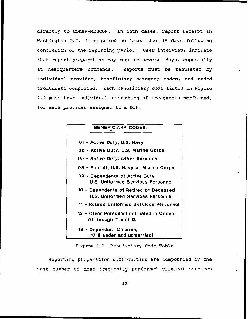
directly to COMNAVMEDCOM. In both cases, report receipt in
Washington D.C. is required no later than 15 days following
conclusion of the reporting period. User interviews indicate
that report preparation may require several days, especially
at headquarters commands. Reports must be tabulated by
individual provider, beneficiary category codes, and coded
treatments completed. Each beneficiary code listed in Figure
2.2 must have individual accounting of treatments performed,
for each provider assigned to a DTF.
BENEFICIARY CODES:
01 - Active Duty, U.S. Navy
02 - Active Duty, U.S. Marine Corps
05 - Active Duty, Other Services
08 - Recruit, U.S. Navy or Marine Corps
09 - Dependents of Active DutyU.S. Uniformed Services Personnel
10 - Dependents of Retired or Deceased
U.S. Uniformed Services Personnel
11 - Retired Uniformed Services Personnel
12 - Other Personnel not listed in Codes
01 through 11 and 13
13 - Dependent Children,(17 & under and unmarried)
Figure 2.2 Beneficiary Code Table
Reporting preparation difficulties are compounded by the
vast number of most frequently performed clinical services
12

treatment codes (over 280), and over 82 laboratory services
codes. "The clinical services treatment code weight factors
are based on time values and are termed composite time values
(CTV). A CTV of 1 equals 17 minutes." [Ref. 1) Similarly,
each laboratory services code is assigned a composite lab
value (CIV). One CLV is assigned a six minute value. A wide
variance in possible point value complicates reportinq; in
clinical services, for example, blood pressure recording is
assigned a CTV of .3, while fitting for a partial denture with
precision attachments is assessed a 25.9 CTV. For lab
services the variance is greater; from 1 CLV for issuing
teeth, to an assigned CLV of 220 for creation of an Andrews
Bridge (an entire dental restoration). This information is
valuable as a management tool for examination of historical
trends, administration and resource allocation decisions, and
in comparison/analysis of various ratios; i.e., total CTV's
divided by number of providers, CLV's by available time, etc.
The submission to COMNAVMEDCOM in the form of NAVMED
6600/8 is a monthly compilation of Daily Treatment Records
from all providers at a given DTF. The Unit Identification
Code (UIC) identifies the activity submitting the report.
NAVMEDCOMINST 6600.1B states that each Dental Treatment
Facility must submit the OCR format NAVMED 6600/8 via priority
mail to arrive at COMNAVMEDCOM "not later than the 15th day
of the month following the month for which the treatment was
provided." [Ref. 1] The instruction also directs that a copy
13

of the submission be mailed to the "appropriate geographic
naval medical command (geographic NAVMEDCOM) . These mandated
stipulations create time constraints that leave little or no
time for the responsible headquarters command to review
subordinate clinic's NAVMED 6600/8.
While the current technology exists within the DON to
expedite reporting system requirements, the rigid adherence to
the OCR-A typewriter and carbonized form creates a reporting
bottleneck causing needless delays and repetition. The time
lost in preparing and submitting the NAVMED 6600/8 each month
is valuable time that could be spent on patient care. The
present system can support only one clinic and lacks the
provision for data import to meet mandated reporting via their
respective headquarters, in effect rendering each DTF an
independent command.
B. REQUIREMENTS DEFINITION
The purpose of this phase is twofold. It defines data
requirements (objects) that must be represented in the
database and outlines functional requirements; (update,
display, and control mechanisms) necessary to support the
Dental Information Retrieval System. User requirements are
the "blueprint" for database design. [Ref. 3] Accurate
identification and representation of user requirements is
critical tu the success of the entire development effort.
An object-oriented methodology will be used to define and
further clarify actual user requirements. This methodology
14

includes the identification of objects, development of object
views, and materialization of these views into applications.
"An object is a named collection of properties that
sufficiently describes an entity in the user's work
environment." An entity is "a class of things that exist in
the users business environment." [Ref. 3)
1. Data Reauirements
Objects necessary for inclusion in the database were
identified by examining NAVMEDCOMINST 6600.1B, current manual
DIRS data flow (Figure 2.1), and from personal interviews of
dental technicians and dental managerial personnel. Through
the processes described above, objects were identified and
transformed into object diagrams (Appendix A).
a. Object Description
In defining the requirements of a database
application, it is important to identify and capture those
objects that accurately describe the aspects of the user's
work environment which the database is intended to model.
Recall that "an object is a structure that represents an
entity." [Ref. 3] Multi-valued properties are allowed to
have more than one value, and may themselves be objects or
non-object properties. "Object properties represent other
objects" while "non-object properties represent descriptive
characteristics"of objects. User's environment objects and
properties identified are described below. Depictions of
objects are accomplished through the use of object diagrams
15

(see Appendix A.) "An object diagram describes objects in the
user's world and their relationship to one another." The
seven boxes depicted in Appendix A each represent a single
object. Listings inside each box contain all properties of
that object. Note that some properties listed are portrayed
in lowercase letters, while others are enclosed in small boxes
and are written in uppercase letters. These properties are
themselves other objects. For example, the PROPERTY
"COMMAND" inside the box titled "STATS (HQ)" denotes that the
object COMMAND is a property of the object STATS (HQ). The
subscript 'MV" beneath some of these boxes denotes that the
property is multi-valued.
The Provider Object represents individual
personnel who provide direct and indirect patient care. A
laboratory technician performing a procedure such as waxing a
crown, is an example of indirect patient care. A dentist
delivering the crown is an example of direct treatment.
Individual rank, name, and duty status (active duty, reservist
or contractor) are properties of this object. The multi-
valued Daily object is also a property of the Provider object,
relating the provider with the properties associated with the
Daily object.
The Treatment (DIRS Code) Object represents
treatment codes, the military services-developed series of
codes adopted from the American Dental Association (ADA)
Council on Dental Care Programs. Each treatment is assigned
16
a unique identifying code, description of treatment, and a
composite time value (CTV). There are approximately 300
codes. Treatment codes are identified in full and can be
found in NAVMEDCOMINST 6600.1B. The proposed DIRS will
include the list of codes and their meaning, to eliminate the
inconvenience of looking the information up in the
NAVMEDCOMINST.
The Command Object, which consists of the Unit
Identification Code (UIC), the command name, and the MEPRS
codes, identifies the submitting unit. The MEPRS code is also
known as the UCA code, and is used only for NAVMEDCOM Naval
Hospitals and Naval Dental Commands. The four digit code for
each work center is required on each NAVMED 6600/8 submission,
and delineates the type and location of dental procedures
performed. The Command object also includes the multi-valued,
Provider and Year objects.
The Daily Object represents entries for a
particular data entry session, that include each instance of
an individual provider providing a treatment to a patient in
one of the nine beneficiary categories. The NAVMEDCOMINST
does not specify a requirement that daily treatment
information be automated, but a hardcopy of the Daily
treatment work sheets must be kept on-hand for two years.
In order to support both headquarters and branch
clinics, three additional objects have been identified. The
responsible headquarter's command has indicated the desire to
17

maintain a year's compilation of information on all its
component commands. Each branch clinic must maintain data
specific to their clinic for a year. Both commands want to
store information for a period of one year, but neither
command has large capacity ADP storage hardware. Both want
the capability of retrieving data by month in the appropriate
format stipulated in NAVMEDCOMINST 6600.1B. For these
reasons, a Year Object, and Monthly Object are needed to track
branch clinic information and a Stats (HQ) Object is needed to
keep all statistical information on all its subordinate
commands. A Unit Identification Code (UIC) entity is required
to uniquely identify a specific DTF. The Year and Monthly
objects are very similar in structure. Each object consists
of information relevant to the treatment performed on a
particular beneficiary category code, the provider performing
treatment and provider status, and the calendar month the
treatment was effected. Object definitions are provided in
Appendix B.
b. Domain Definitions
In addition to identification of required objects,
and user views of those objects, further clarification of user
requirements is achieved through specification of domain
definitions. A domain is defined as "a description of the
allowed values of an attribute." [Ref. 3, p. 150] Domain
definitions include both physical descriptions of allowable
data values, and logical descriptions pertaining to attribute
18
meanings. The domain definitions specified are provided in
Appendix C.
2. Functional Requirements
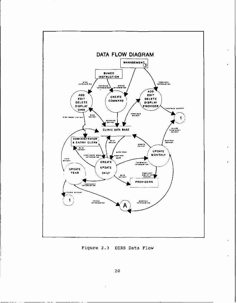
a. Data Flow Diagrams
Using the object requirements identified in the
previous section, and proceeding with the object-oriented
methodology, a dataflow diagram (see Figure 2.3 or Appendix
D) was developed depicting required actions on objects
identified.
A dataflow diagram portrays the business functions and theirdata interfaces. Dataflow diagrams can be used to identifyapplications and the data they use. Four symbols are usedin a dataflow diagram. Internal system processes are shownin circles, while external processes are shown inrectangles. Data interfaces are illustrated with namedarrows, and stored data, including the database, is shownbetween parallel horizontal lines. [Ref. 3]
As depicted in Figure 2.3, update mechanisms (add,
edit and delete) and display mechanisms are required for DIRS
and PROVIDER _Dject. Daily transactions cannot be recorded
unless valid DIRS or provider information is recorded in the
database. This information is provided by either
NAVMEDCOMINST 6600.1B or DTF managers. Both provider and DIRS
treatment code are unique, only one provider may be assigned
provider code 100 for example. For the same reason, only
treatment code "0120" may represent a periodic oral
examination. The proposed system shall provide update
mechanisms insuring that duplicate records will not be created
for those objects. Management assigns provider codes to new
p-oviders reporting onboard. To preserve data integrity, a
19
DATA FLOW DIAGRAMMAN AGCUE N
ADD CREAT E EDI
UDTE DISPAAY
igue23 ISDaaFo
2.0

current provider listing will be generated for management
review and to assist them in assigning provider codes to new
personnel.
The COMMAND object will be created only once upon
initial installation of the proposed system. Command and
MEPRS information are derived from COMNAVMEDCOMINST 6600.1B
and DTF management. This object itself serves as a control
mechanism. Users will only be authorized to access commands
specified in this object.
The heart of the required application is the
creation and update mechanisms for the DAILY object. For it
is through these mechanisms that the MONTHLY and YEARLY
objects are updated. It will be the responsibility of the
data administrator or data entry clerk to input provider work
information which will update the DAILY, MONTHLY, and YEARLY
objects. Appendix E delineates update, display and control
mechanisms for each object described above.
A STATS (HQ) object is created and updated through
monthly and yearly information submitted by subordinate
commands. A headquarters database must be maintained for a
minimum of one year, consisting of the aggregate provider
production information for each subordinate command. This
object will provide management with the central depository to
meet internal and external reporting requirements. The
dataflow diagram presented in Figure 2.4 represents these
21
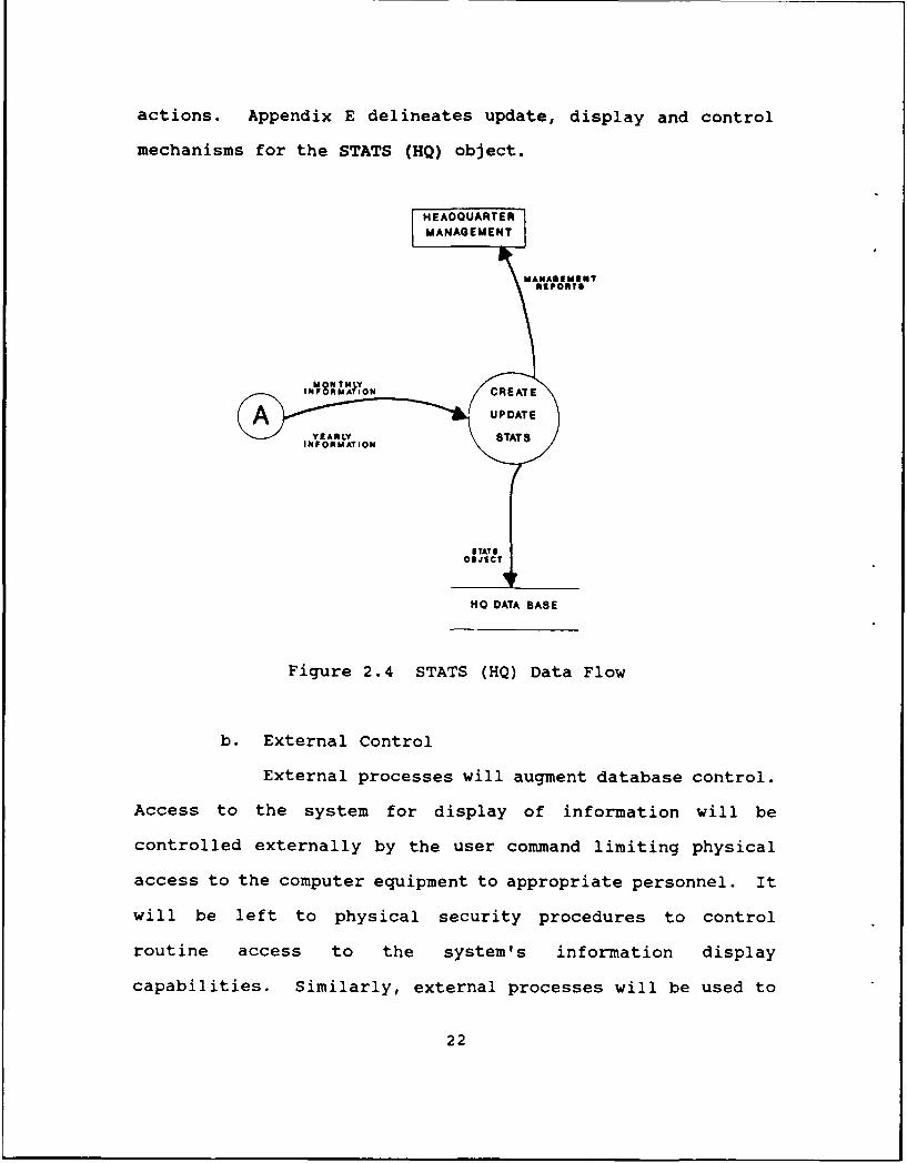
actions. Appendix E delineates update, display and control
mechanisms for the STATS (HQ) object.
HEADQUARTERMANAGEMENT
MAN AGEME SNT
IN I N8AF1 'ON CREATE
$TAT$OB JECT
HO DATA BASE
Figure 2.4 STATS (HQ) Data Flow
b. External Control
External processes will augment database control.
Access to the system for display of information will be
controlled externally by the user command limiting physical
access to the computer equipment to appropriate personnel. It
will be left to physical security procedures to control
routine access to the system's information display
capabilities. Similarly, external processes will be used to
22

help regulate database updates. The user's manual (Appendix
K) will provide structured guidelines for system use including
data update procedures.
c. Other Requirements
During the interview process, several problems
were identified. Data entry may not be accomplished on a
daily basis. Provider's daily work sheets may be totalled and
submitted at the end of the work week. Even if the provider's
work sheet is submitted daily, the technician entering DIRS
information may not have sufficient time to input data until
the next day or even several days later. The DIRS must be
flexible enough to handle this type of erratic schedule of
data input. The DAILY object is needed to verify that data
entered corresponds to the data reported on the provider's
work sheet.
Due to data storage limitations, the structure of
the proposed system needs to offer several additional
capabilities to users; file size grows only as required by the
number of actual instances of treatments provided, not by
arbitrary structure based on all possible treatments, per all
beneficiary categories for each provider. An application with
relations structured in this manner would soon exhaust
available data storage capacities unless frequently purged.
An efficient database design shall allow treatment instances
to be updated and totalled in year-to-date totals rather than
adding an additional record, yet still provide data extraction
23

capabilities for internal and external reporting. Appendix H
contains examples of sample reports.
The seven objects identified earlier are required
in the structure of the proposed DIRS to meet the following
requirements:
- The system must provide update mechanisms.
- Utility functions must be incorporated into the system toprovide easy file backup and file organization such asindexing.
- The system dialogue must be easy for non-ADP personnel tofollow and use.
- The system must have the capability of exportingrequested information to floppy disk and at theheadquarters level, to import branch clinic data to theHeadquarters database.
Several reports have been requested by the
sponsoring activity. Headquarters must be capable of
generating the required branch clinic OCR monthly report
directly onto NAVMED 6600/11. Annual treatment reports
similar in format to the monthly report shall be printed on
request. Summaries and full Providers' performance reports
also shall be available on request. Individual provider
reports shall be generated monthly and submitted to the
corresponding provider for his or her own personal performance
information.
An additional requirement identified by the
sponsoring activity, as discussed previously, is support for
multiple DTF's under one command. During user interviews, it
was determined that the proposed DIRS must be capable of
24
supporting up to nine DTF's under a single Headquarters
command. Further, with multiple DTF's, the possible variety
of hardware configurations requires that the proposed DIRS be
generalized or "generic" to support the varied functions and
requirements of a specific DTF. Though it may not always be
the case in systems analysis and design, in this instance, the
users' view of the objects to be captured by the DIRS,
coincides closely with the actual application functional
requirements used to model the users' view of the system.
The computerized DIRS proposed and developed in
the scope of this thesis will meet the reporting requirements
of a Headquarters Clinic with up to nine subordinate DTF's.
Through the user-interview process and dental clinic command
structure review, the provision to support up to nine DTF's in
the proposed program was identified to allow future expansion
of the program in the event of dental command reorganization,
without requiring modification of the database structure.
Currently, NAVDENCLINIC Long Beach, Ca., is one of the largest
DTF Headquarters commands with five subordinate DTF's.
In addition to the required features, the proposed
system will allow subordinate units to report their monthly
totals via either modem or "floppy" medium to their
Headquarters Clinic. At the Headquarters level in the
proposed DIRS, the input of the subordinate DTF's will be
combined to generate the requisite NAVMED 6600/8 for
submission to COMNAVMEDCOM. The proposed DIRS offers the
25

elimination of much of the manual handling and transcribing of
daily count sheets, and offers accurate computerized
completion of the OCR-A NAVMED 6600/8.
Update, Display and Control Mechanisms required
for the DIRS may be found in Appendix E.
26
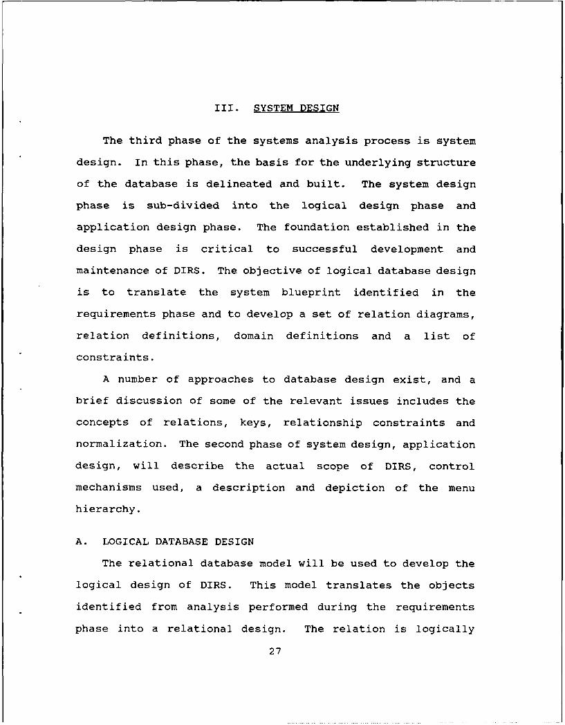
III. SYSTEM DESIGN
The third phase of the systems analysis process is system
design. In this phase, the basis for the underlying structure
of the database is delineated and built. The system design
phase is sub-divided into the logical design phase and
application design phase. The foundation established in the
design phase is critical to successful development and
maintenance of DIRS. The objective of logical database design
is to translate the system blueprint identified in the
requirements phase and to develop a set of relation diagrams,
relation definitions, domain definitions and a list of
constraints.
A number of approaches to database design exist, and a
brief discussion of some of the relevant issues includes the
concepts of relations, keys, relationship constraints and
normalization. The second phase of system design, application
design, will describe the actual scope of DIRS, control
mechanisms used, a description and depiction of the menu
hierarchy.
A. LOGICAL DATABASE DESIGN
The relational database model will be used to develop the
logical design of DIRS. This model translates the objects
identified from analysis performed during the requirements
phase into a relational design. The relation is logically
27

equivalent to a file, which contains rows and columns. A row
in a relation table represents a record or tuple. Each column
in a relation is termed an attribute or field. A process
known as normalization is used to collect related data
properties into robust well-designed relational (relation)
tables. A well-structured design will "allow rows to be
inserted, deleted, and modified without resulting in
inconsistencies or errors in the stored data." [Ref. 3]
Normalization serves to identify and eliminate these
modification anomalies. Relations which correspond to DIRS
are graphically depicted in Appendix F.
1. Normalization
Gathering or grouping of properties or data items into
relations is an important aspect of database design. This
process of "normalization" is used to eliminate database
design weaknesses or flaws. These problems or "anomalies" as
they are called, can result in inadvertent deletion of facts
in a relation, or artificial and unintended restrictions on
entity insertion. These modification or update anomalies are
termed deletion anomalies or insertion anomalies respectively.
The theoretical framework concerning proper database design is
derived from early database design work of E.F. Codd who
provided the definition of possible normal forms that
relations may take. Normalization is the process by which we
"troubleshoot" the database structure to identify and remove
anomalies discovered. To do this, data items or properties
28

are grouped into relations as previously discussed. Object
diagrams provided in Appendix A and relation diagrams provided
in Appendix F depict groups of related properties upon which
normalization is based. All relations are in at least first
normal form. In the relations created within the scope of
this thesis, each is at least in third normal form (3NF). "A
relation is in third normal form if it is in second normal
form and has no transitive dependencies." [Ref. 3:p. 143)
Second normal form is defined as a relation in which "all non-
key attributes are dependent on all of the key." [Ref. 3: p.
142]
2. Keys
"A key is a group of one or more attributes that
uniquely identifies a row. Every relation has at least one
key. Sometimes the key is one attribute." [Ref. 3:p. 139]
In the example provided in Appendix F, the keys are
underlined. In the PROVIDER object, the underlined attribute
is Prov Code, a three digit code which serves to uniquely
identify any provider in the system. It is possible that a
group of attributes will be required to "functionally
determine" (serve as a key to uniquely identify) other non-key
attributes.
3. Relations
Relations are created by examining object diagrams
(Appendix A) to determine relationships among objects
(depicted in Appendix F), then transforming these objects into
29

relations such as those described below. Depiction of an
object may be relatively simple or may require the composition
of several relations. Database objects (Appendix A), and
relation diagrams (Appendix F) provide examples of such
composition. A simple object contains only single-valued,
non-object properties, and may be represented by a single
relation. A composite object contains one or more non-object
multivalued properties, and requires more than one relation
for their representation. A compound object contains at least
one object property, requiring translation of that object into
a minimum of two relations. As an example, the MONTHLY object
in Appendix A contains the object property COMMAND and the
multivalued object DAILY. Each of the seven objects in
Appendix A is a compound object, containing at least one other
object property each depicted by its own relation as depicted
in Appendix F. [Ref. 3]
4. Relationships
A binary relationship involves only two record types.
Whereas an object was converted on a one-to-one basis into a
relation (record type), relationships between those record
types are not necessarily limited to one-to-one. In fact, in
this database the majority of relationships are one-to-many.
Referring again to the relation diagrams of Appendix F, a
given STATS (HQ) may have multiple commands associated with
it, as indicated by the "fork" on the command end of the
connecting line. Similarly, a command can have many providers
30

and a provider will provide many treatments to many
beneficiary category codes during the course of a daily
(visit).
There are a number of classifications pertaining to
the degree of relationship that exits between objects, varying
in complexity from no relationship between objects (0:0), to
a many-to-many relationship (M:N). For example, in a one-to-
one (1:1) relationship, one record is related to only one
other record of another type. Additional explanation is
required for notation used in Figure 3.1 and Appendix F, to
indicate the type of relationship between record types.
Beyond the "forked" end of the line which is used to indicate
a "many" (as in one-to-many), on the line connecting two
objects or relations together, there may be either a circle or
a bar. This notation is found on both ends of the line
connecting the records, and is used to describe an optional or
mandatory association between records. These associations are
a type of relationship constraint.
5. Relationship Constraints
Relationship constraints such as those presented in a
simplified version of DIRS Relationships are provided in
Figure 3.1 below, with the detailed relationship structure
provided in Figure 3.2 and Appendix F. If a relationship is
mandatory, a bar will be found perpendicular to the opposite
end of the line (side closest to the mandatory association).
In the case of the COMMAND and PROVIDER objects in Figure 3.1,
31

STATS (HQ)
COMMAND
MONTHLY
PROVIDER TREATMENT
LDAILY
Figure 3.1 DIRS Relationships
it is mandatory that a COMMAND have a PROVIDER, and that a
PROVIDER have a COMMAND. However, the circle found nearest
STATS (HQ) on the line connecting COMMAND and STATS (HQ)
indicates that while STATS 1W must have a COMMAND associated
with it, a COMMAND may have a (HQ) associated with it, but it
is not mandatory, as COMMAND could stand alone.
To accommodate the nuances of this reporting environment,
and attain user functional requirements, the structure of
database object relationships depicted in Figure 3.2 was
32

developed. Database relations identified remain identical to
those represented above in Figure 3.1. The STATS (HQ)
relation consists of the key attribute, UIC and each attribute
belonging to COMMAND. UIC can serve as a key attribute for
each relation because this five-number code is uniquely
assigned to individual units. Relations containing other
relations are identified by attribute names presented in all
capital letters (with the exception of UIC). COMMAND, then,
contains two other relations; PROVIDER and YEAR, each
containing all attributes displayed within their respective
boxes above, and in both appendices A and B. The Name
attribute refers to Navy-assigned command plain language
addresses, while MEPRS Code describes the four-digit work
center code required on DOD dental reports. COMMAND has
obvious relationships with PROVIDER and YEAR, as diagrammed by
vertical lines connecting these relations, and more subtle
relations through these two relations to all other relations.
No object exists in isolation. it must be tied (related) to
at leasz one other object. These relations may be optional
(circles) or mandatory (short horizontal line) as described
earlier, and evidenced in Figure 3.2.
YEAR, as defined by key relations COMMAND and MONTHLY,
also contains an individual attribute for each beneficiary
category code listed in Figure 2.2.
In this manner, all treatments performed on members of a
specific beneficiary code, for a particular month and at a
33

STATS (HO)
I UIC OMMAND
COMMAND
IJIC I Nara@ MEPERS Code IPROVIDER YA
YEAR
C2OMMAND I MONThLY I Tot Yr BCet 01 1Tt Y, mCt .. Tot Yr BCat 18I
MONTHLY I
CO-)m MAND I DAILY I MOVh ToW MI. SCat 01 lot Mon SCat 021 1Tat Man SCat iS
TREATMENT
I DIRS Cod. IDeoription Comp Value DAILY
PROVIDER -k
ProY.1 -Cde F.Name I L-NAMIa Ran~k IDuty Status DAILIY
DAILY
PLROVIDER ITREATMENT IDate ITat 01y 60at 01 Tat Dly BCat 02 lot Oly B0at 1I
Figure 3.2 DIRS Relation Diagram
specific command, are delineated and totalled separately.
Similar structuring of attributes contained in both MONTHLY
and DAILY, allows provisions for data extraction or
combination, while always retaining identification of data
origin. For example, PROVIDER contains the key attribute Prov
Code, in addition to attributes; first name, last name, rank,
duty status, and the DAILY object. This structure means that
if a provider performs a treatment on a specific day, each
34

attribute of TREATMENT; DIRS code, description of treatment,
composite value and DAILY, is included in data specific to
that provider. To identify a unique DAILY object instance;
PROVIDER, TREATMENT and date, together serve as keys. User
requirements identified the necessity for storage of a year of
DIRS data on disk at a time. To support this specification,
the DAILY relation is designed as a temporary object, with
data values added to update MONTHLY, at each convenient data
entry session. Structured in this manner, all required data
manipulation capabilities are supported with minimum disk
storage overhead. Inclusion of daily beneficiary category
totals to DAILY, permits accurate characterization and
summation by category, stats (HQ), individual command, year,
month, provider or treatment, for a particular instance or
total to date.
The structure described above offers several advantages to
users; file size grows only as required by the number of
actual instances of treatments provided, not by arbitrary
structure based on all possible treatments, per all
beneficiary categories for each provider. An application with
relations structured in this manner would soon exhaust
available data storage capacities unless frequently purged.
Efficient database design allows treatment instances to be
updated and totalled in year-to-date totals rather than adding
an additional record, yet still provide data extraction
capabilities for internal and external reporting. Several
35

reports are supported in addition to provisions for automatic
formatting and generation of the required monthly NAVMED
6600/8 using an OCR font printer. User desires for daily,
monthly, annual, provider statistics and major treatment
reports shall be supported options in the Report menu.
Additional provisions for file import/export and maintenance
shall be supported as described in the file utilities menu
section. Support requests for possible expansion of up to
nine subordinate DTFs under a single headquarters command is
provided in accordance with user criteria. This support means
that data from subordinate commands exported to a headquarters
may be sub-totalled in as many as ten total categories.
Additional features are discussed under menu hierarchy
descriptions later in this chapter.
B. APPLICATION DESIGN
In following the object-oriented methodology, the
application design phase will include determination of number
and scope of applications, design control mechanisms for
identified applications, and identify specific procedural
logic. Additional considerations include; design
materializations, database security and integrity.
The data flow diagrams developed in the user requirements
phase to help document flows of information, identify scope of
required information needs, and describe required structure of
36

the organization, are used in the current phase to assist in
the creation of the functional hierarchy.
1. Application Control Mechanisms
"An application is the user's interface with the
database." [Ref. 3] This interface must include the capacity
for recognizing when data values entered are of an appropriate
type and are within the intended range for the respective
field. The users and developers consider extensive use of
menus as the most appropriate user-system interaction method
for a given application. On-screen templates (or masks, as
previously discussed) will aid data entry process by
restricting allowable data types (alphabetic, numeric, etc.)
to the appropriate field. Pop-up help screens provide
additional control in guiding users. Most DIRS on-screen
messages are self-explanatory. Pre-established escape
procedures, such as pressing any key on the initial or first
blank field will allow users to abort an operation and return
to a previous menu, or to exit the system entirely. An
additional escape provision is available from within any level
by pressing the escape key.
Intuitive feel and simplicity of design allow not on.ly
shortened operator training time, but also permits the
developers to limit deviations from the acceptable range of
values for a given task or command. Consistent use of
function keys to provide case sensitive help screens and
37

standardized conventions for interfacing with the application,
also streamline user familiarity process.
As previously stated, to accommodate the wide variety
in computer literacy existing among potential system users, a
menu-driven application was selected as the most appropriate
application control mechanism. The next design step required
the determination of menu hierarchy. Furthermore, it was
determined that an object/action approach would best serve
user needs. An object/action approach means "the highest-
level menu offers the user a list of objects that might be
processed, and lower-level menus enable the user to indicate
the action to be taken on the selected object." [Ref. 3]
An important design consideration for DIRS developed
in the course of this thesis is not limiting the system to
only one command. For example, Unit Identification Code
(UIC), command name and UCA code must not be hardcoded in the
program. This requirement will be accomplished upon initial
installation of the system. A memory file will be created at
that time containing the UIC, Command name, and related UCA
codes for the appropriate command. Creation of this object as
a memory file within random access memory (RAM) creates
efficiency gains, saving multiple disk seek and access times.
This object is frequently called as a visual aid in the form
of a pop-up menu. As an example, a subordinate command is not
required to reenter its UIC for each instance of DIRS data
38

input for a daily transaction, as object relation design
results in automatic updates to related attributes.
C. MENU HIERARCHY DESCRIPTIONS
Menus used in the DIRS application were derived from an
analysis of user requirements and data flow diagrams. Menus
corresponding to these diagrams and structures are briefly
described in the following section. Figure 3.3 depicts the
MENU HIERARCHY
MAIN
L.-I L. - H.
Ull Sl SEPSTI DARE AIIIE ESOAIS
Ago AD1 SAI EFINDET IMPDR?aII PEO1EN SEPONT Do F ILEI PILES
BIT IDIT MONT14Y SAKUP EXPONI
SIS PEOmIS.S Ipoor m FILeS 'IL1S
:ILITK gELTiE a HUAL oT
ains PiTSei I POST F5W TEAl IPOITS
LINT LIS1 PNO IDl T IAtSS
ina PEOVIDNE 101 am TO ISa NOTN
TolS0NET BIPOIT
SURT NEW NEARlIE 011YL
Figure 3.3 Menu Hierarchy
menu structure hierarchy which provides graphic information
pertaining to specific applications, objects, or tasks
assigned to a block, module, or sub-module supported.
39

1. Main Menu
DIRS main menu shall offer system user options
depicted in Figure 3.4. In every menu screen provided, an
option may be selected by highlighting the desired selection
or by typing the first letter of the desired option. The
final option available on each menu screen is a provision for
exiting to the next higher level menu, or in the case of the
main menu, exiting DIRS to the operating system.
As depicted in the following diagrams, each menu
screen in the menu hierarchy exhibits common structure,
consisting of three distinct parts. User information is
provided in part A, with DTF command name, system name,
current time and date, and screen number identified. Part B
presents available menu options, part C provides option
selection instructions and error message display.
Heading
A NAVAL DENTAL CLINIC, USN 13:17:17 01/13/90DENTAL INFORMATION RETRIEVAL SYSTEM SCREEN # 1.0
MAIN MENU
INPUT DIRS DATACHANGE DIRS CODES
B UPDATE PROVIDER CODESQUERIESFILE UTILITIESHEADQUARTERS ONLYQUIT
C USE UP AND DOWN CURSOR KEYS t TO HIGHLIGHT ITEM AND
PRESS<RETURN>
Prompt & Status Box
Figure 3.4 Main Menu Screen
40

To operate DIRS, users shall enter the first letter
which corresponds to the item in the menu body to be selected,
or move the arrow keys (t4) to highlight an option. All menus
have a RETURN option to return to next higher menu in the
hierarchy.
a. Input DIRS Data
The first screen that will appear when selecting
option one (INPUT DIRS nATA) is displayed below (Figure 3.5).
Enter "Y" (yes), if the displayed month is the desired month
for data entry. Enter "N" (no) to select another month. When
"N" is selected a window will appear displaying options that
may be keyed in at the prompt (see open month screen below).
The default month (open month on screen) is the current
calendar month based on the computers system clock.
NAVAL DENTAL CLINIC, USN 08:05:14 01/13/90
DENTAL INFORMATION RETRIEVAL SYSTEM SCREEN # 1.1.1
OPEN MONTH IS JANUARY
IS THIS CORRECT? Y/N
Figure 3.5 Month Prompt Screen
To select the correct month, the three letter
abbreviation is entered at the prompt. For example, typing
41

JUN in the month selection screen will open that month for
data entry. Once the desired month has been opened, the
provider prompt screen will follow (Figure 3.6).
NAVAL DENTAL CLINIC, USN 09:02:20 01/13/90DENTAL INFORMATION RETRIEVAL SYSTEM SCREEN # 1.1.1
JAN JULFEB AUGMAR SEPAPR OCTMAY NOVJUN DEC
ENTER THREE LETTERS OF NEW MONTH:
Figure 3.6 Month Selection Screen
In selecting a provider, the provider code may be
entered directly if the code is known, or by pressing the
<HOME> key, an additional window with the valid provider codes
assigned to the reporting command will pop up. From the
available valid provider codes on screen, the corresponding
number that matches the desired provider code may be entered.
(See Figure 3.7 and Figure 3.8.)
To select a valid provider, enter the matching
number in the leftmost column, i.e.: entering number I'l"
would select provider 100; CDR Navy. The provider code may
also be entered directly on the provider input screen. This
method of provider data entry provides a method to check the
42

NAVAL DENTAL CLINIC, USN 08:18:58 01/13/90DENTAL INFORMATION RETRIEVAL SYSTEM SCREEN # 1.1.1
PROVIDER CODE:
ENTER PROVIDER CODE OR PRESS <HOME> FOR HELP
Figure 3.7 Provider Prompt Screen
NAVAL DENTAL CLINIC, USN 08:18:58 01/13/90DENTAL INFORMATION RETRIEVAL SYSTEM SCREEN # 1.1.1
PROVIDER CODE RANK NAME
1. 100 CDR NAVY, JOSEPH2. 200 LT NAVY, SON3. 300 LT MESIAL, DECAY4. 400 CAPT TOOTH, DECAY5. 455 LT RESERVE, DENTIST6. 500 CDR BUCKLE, PIT7. 600 LT LINGUAL, DISTAL8. 700 ADM DENTAL, SERVICE
PRESS NUMBER OF ITEM, RETURN TO CONTINUE, OR "Q" TO QUIT
Figure 3.8 Provider Selection Screen
provider code file to validate a correct provider code for the
reporting unit. Entering an erroneous code (a code not
currently in the provider code file) results in an error
message indicating that fact, and further prompts the user to
enter another code.
When the provider field is correctly entered, the
screen displayed in Figure 3.9 will follow, prompting the user
43

to enter a valid treatment code. As previously discussed, to
escape the DIRS entry routine, press <RETURN> at a blank DIRS
fJp]d.
NAVAL DENTAL CLINIC, USN 08:05:14 01/13/90DENTAL INFORMATION RETRIEVAL SYSTEM SCREEN # 1.1.2
Entering Data for Provider: CDR JOSEPH NAVY CODE: 100
PRESS THE <HOME> KEY FOR A LIST OF DIRS CODES TOSELECT FROM.
PRESS <RETURN> ON AN EMPTY FIELD TO RETURN TO THEMAIN MENU.
ENTER DIRS CODE:
Figure 3.9 DIRS Code Prompt
Pressing the <HOME> key will display all valid
DIRS codes (Figure 3.10). DIRS treatment code may also be
entered directly on the DIRS prompt screen or the <HOME> key
may be used to assist the user in the event that correct DIRS
codes are unknown. This help function is not a mandatory
input procedure.
To select a DIRS treatment code, the corresponding
number displayed in the leftmost column is selected by typing
the appropriate number ("l"-"9"). Pressing the <Page Down>
44

NAVAL DENTAL CLINIC, USN 08:05:14 01/13/90DENTAL INFORMATION RETRIEVAL SYSTEM SCREEN # 1.1.2
DIRS CODE DESCRIPTION WEIGHT
1. 0001 POUR CAST 2.02. 0002 POUR CAST,FX 4.03. 0003 BOX AND POUR 5.04. 0004 IMP TRAY CUS 4.05. 0005 POUR ALT CAST 5.06. 0006 ARTIC. SIMPLE 1.07. 0007 ARTIC. SEMI 1.58. 0008 ARTIC. FULL 2.09. 0009 SOLDER/PER AREA 4.0
PRESS NUMBER OF ITEM, RETURN TO CONTINUE, OR "Q" TO QUIT
Figure 3.10 DIRS Code Selection Screen
or <Page Up> keys will scroll through the list to display
other treatment codes.
Data entry for an individual provider is
accomplished using screen 1.1.3 depicted in Figure 3.11 by
entering in the correct quantity of procedures completed in
each dental beneficiary category. The <RETURN> key is used
to move the cursor to the next field for data entry. The
steps listed above are repeated until the user has completed
data entry for a particular provider. Data entry error
corrections are accomplished in a number of ways. The user is
prompted with the following query at the bottom of screen
1.1.3; "Is this data correct? Y/N." A negative response
indicated by typing the "N" key, will allow the user to
reenter the correct data. The user may overwrite the data
45

NAVAL DENTAL CLINIC, USN 12:04:39 01/13/90DENTAL INFORMATION RETRIEVAL SYSTEM SCREEN # 1.1.3
Entering Data for Provider: TEST TEST CODE: 100DIRS Code: 0120
Additions Totals YearBeneficiaries to File in File to Date
Category 1 0 0 0Category 2 0 0 0Category 5 0 0 0Category 8 0 0 0Category 9 0 0 0Category 10 0 0 0Category 11 0 0 0Category 12 0 0 0Category 13 0 0 0
ENTER NEW VALUES AND PRESS RETURN
Figure 3.11 Daily Input Screen
displayed on screen by moving the cursor using arrow keys to
the correct field and reentering the correct quantity.
Deletion and editing of values previously entered for a
particular month is accomplished by selecting the desired
month, provider, and treatment, and entering an appropriate
negative value to either cancel or modify the monthly total
for the selected record. To return to the main menu, the
<RETURN> key is pressed with the cursor on a blank DIRS input
field or typing 'Q" when prompted from the help screen. When
a month and provider have been selected, the user may continue
adding new treatment data without the requirement of returning
to the main menu for each instance. To enter data for another
46

provider, users must return to the main menu and select the
desired month and treatments. The system shall default to the
month of last data entry. Upon termination of a data entry
session, a final query will prompt the user with the following
message; "Do you wish to save this data? Y/N." Selecting "N"
will not save the data entered during the session. This
particular feature is provided as another control mechanism,
allowing the user to correct or terminate a data entry session
without arbitrary input of inadequately screened or inaccurate
data to the database. Selecting "Y" will automatically result
in appropriate updates to the Daily, Monthly, and Yearly
object files. Selection of "Y" will also result in the
display of the following messages in the status box of the
menu screen (part C); "Adding to Monthly Total" and "Adding
to Yearly Total," informing the system user of action in
progress. Again, listing command providers is provided as a
convenience to the system user.
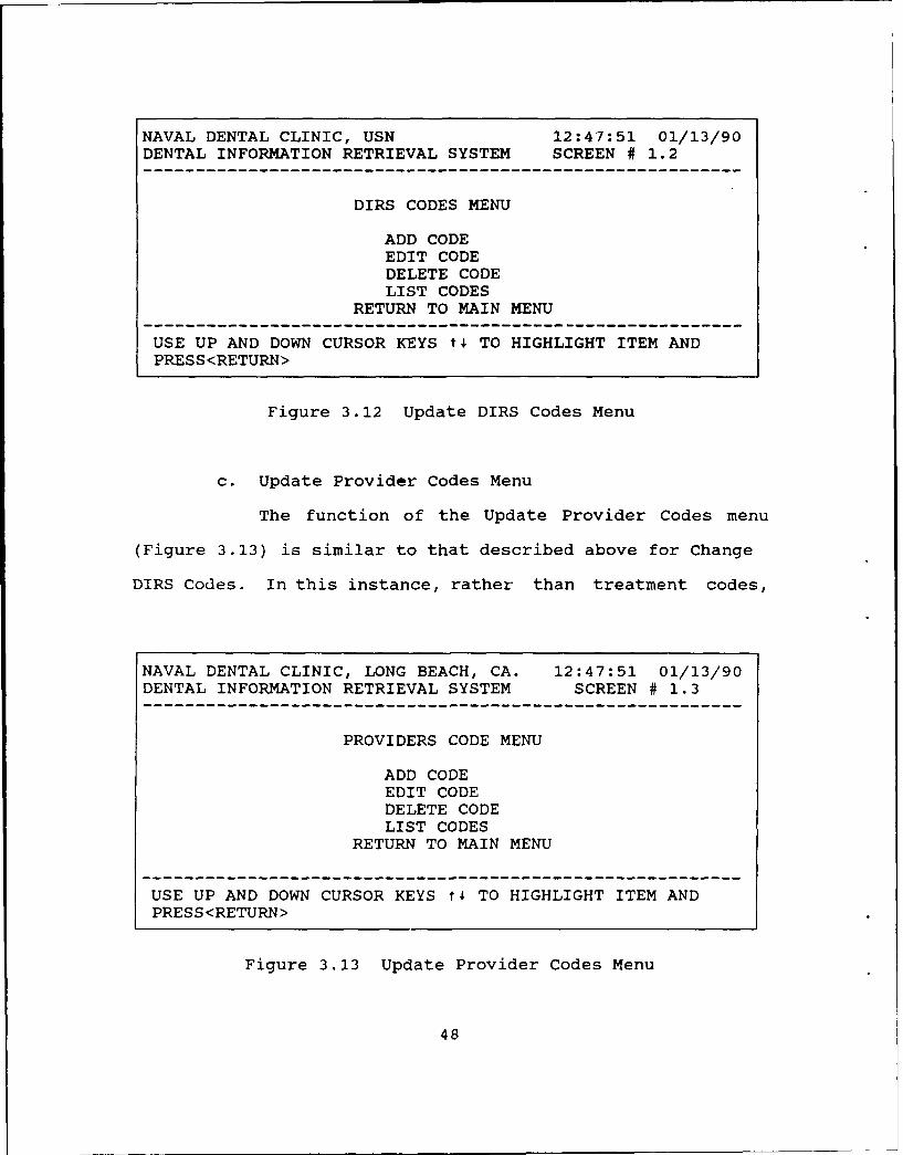
b. Change DIRS Codes
Selection 2 from the main menu (CHANGE DIRS CODES,
Figure 3.12) is used to add, delete, or edit the DIRS (treat-
ment) code file. Deleting means erasing of an existing code
in the file. Editing means changing an existing code. When
callinq these functions, the procedure is similar to that of
data entry described in the DIRS entry section.
47
NAVAL DENTAL CLINIC, USN 12:47:51 01/13/90DENTAL INFORMATION RETRIEVAL SYSTEM SCREEN # 1.2
DIRS CODES MENU
ADD CODEEDIT CODEDELETE CODELIST CODES
RETURN TO MAIN MENU
USE UP AND DOWN CURSOR KEYS t4 TO HIGHLIGHT ITEM ANDPRESS<RETURN>
Figure 3.12 Update DIRS Codes Menu
c. Update Provider Codes Menu
The function of the Update Provider Codes menu
(Figure 3.13) is similar to that described above for Change
DIRS Codes. In this instance, rather than treatment codes,
NAVAL DENTAL CLINIC, LONG BEACH, CA. 12:47:51 01/13/90DENTAL INFORMATION RETRIEVAL SYSTEM SCREEN # 1.3
PROVIDERS CODE MENU
ADD CODEEDIT CODEDELETE CODELIST CODES
RETURN TO MAIN MENU
USE UP AND DOWN CURSOR KEYS t4 TO HIGHLIGHT ITEM ANDPRESS<RETURN>
Figure 3.13 Update Provider Codes Menu
48

update function and display function pertains to the treatment
provider at a given command.
d. Report Menu
Branch clinic report menu (Figure 3.14) presents
users with a number of options related to reporting of DIRS
data by various chronological periods. Using the options
available in this menu, the current total of treatments,
treatments by provider, by command, etc., may be obtained.
Additionally, a Major Treatment Report option is available as
a menu selection for internal reporting purposes. Examples
of each report selection are provided in Appendix H.
NAVAL DENTAL CLINIC, LONG BEACH, CA. 12:49:38 01/13/90DENTAL INFORMATION RETRIEVAL SYSTEM SCREEN # 1.4
REPORT MENU
DAILY REPORTMONTHLY REPORTANNUAL REPORTPROVIDERS STATS.MAJOR TREATMENT REPORT
RETURN TO MAIN MENU
USE UP AND DOWN CURSOR KEYS t4 TO HIGHLIGHT ITEM ANDPRESS<RETURN>
Figure 3.14 Branch Clinic Report Menu
49

e. File Utilities Menu
Menu screen in Figure 3.15 offers system users the
ability to reindex, backup, transfer, and start a new
recording year all from within the DIRS application.
Providing these necessary functions from within the system as
menu-driven options helps simplify the normally onerous and
often neglected tasks such as backing up system data.
The reindex data files option should be selected
when the system shows signs of incorrect operation such as
incorrectly assigned totals or data. As an example, reports
may display zero work for all providers at a specified command
for a given month. If this information is incorrect, using
the reindex option will reassign the appropriate key field to
their respective records. The reindex feature is often
required in any database system. Power surges, improper file
closing and hardware malfunctions are examples of possible
causal factors for index distortion. The reindex option is
provided to reestablish the proper links and pointers to
correct the potential damage caused by these malfunctions.
Simplicity inherent in the menu interaction format, should
help increase the frequency of back-ups and maintenance of
application data.
The "Start New Year" option is provided when the
users wish to begin recordkeeping functions for a new
reporting year; either calendar, fiscal or other arbitrary
selection. Failure to select this option when starting a new
50

NAVAL DENTAL CLINIC, LONG BEACH, CA. 13:50:16 01/13/90DENTAL INFORMATION RETRIEVAL SYSTEM SCREEN # 1.5
FILE UTILITIES
REINDEX DATA FILESBACKUP DATA FILESSTART NEW YEARTRANSFER DATA TO DISKRETURN TO MAIN MENU
USE UP AND DOWN CURSOR KEYS t TO HIGHLIGHT ITEM ANDPRESS<RETURN>
Figure 3.15 File Utilities Menu
reporting period will result in overwritten data values and
incorrect totals for the selected period.
The "Transfer Data to Disk" option is selected to
transfer data for a monthly reporting period to a "floppy
disk" for subsequent export to the appropriate Headquarters
command. Production of the OCR rpport form may only be
accomplished at the Headquarters level after import of the
transfer files.
Selection of transfer routine will transfer the
working file to a floppy disk. The UIC window located in the
lower right corner depicted in Figure 3.16 prompts the user
to select a number; 1 through 5. The number "5" is
representative of a Headquarters command with five subordinate
DTFs. This number will reflect the actual number of DTFs
supporting as few as one or as many as nine. If the system
51

NAVAL DENTAL CLINIC, USN 13:51:59 11/10/89DENTAL INFORMATION RETRIEVAL SYSTEM SCREEN # 1.5.4
ENTER UIC:
ENTER MONTH OF REPORT: *** VALID UIC ***i.e.: 1) 00000 - HQ & NOWHERE
2) 55555 - PORT NEVERSAIL3) 55511 - POINT HERE4) 51515 - CHINA5) 99999 - C 0 BEACH
0) RETURN TO MAIN MENU
SELECT (0 - 5)? 0
Figure 3.16 Transfer Data to Disk Screen
is being used at a branch clinic, only one UIC is displayed
and selected. User input of the correct UIC is critical,
because a UIC FIELD will be appended on the TRANS. FILE based
on the UIC input. The TRANS. FILE is the database export file
to be received by the corresponding Headquarters command.
This routine will be selected when a subordinate DTF is
required to submit data to headquarters. Regardless of
transmission medium, the export routine must be selected to
transfer all data to floppy disk, prior to submission of the
updated monthly data requirements. The export procedure
described above provides a necessary if subtle control
mechanism ensuring that data back-ups are performed at least
once a month. When properly labeled with the appropriate UIC,
and month of transfer, the floppy disks containing the TRANS
52

database file (dbf) provide a convenient source of back-up
data. The menu status box (part C) will provide a prompt to
insert a floppy disk into the appropriate drive, and a message
indicating the number of records transferred.
f. Headquarters Menu
Headquarters menu (Figure 3.17) is intended for a
Headquarters command to facilitate transfer of DIRS data from
subordinate dental commands, and the obligatory submission of
DIRS reports. To that end, file import/export facilities are
provided as menu options for operation from within the DIRS
application.
NAVAL DENTAL CLINIC, LONG BEACH, CA. 13:53:44 01/13/90DENTAL INFORMATION RETRIEVAL SYSTEM SCREEN # 1.6
HEADQUARTER'S MENU
IMPORT FILESEXPORT FILESDO REPORTS
START NEW YEAR (HQ ONLY)RETURN TO MAIN MENU
USE UP AND DOWN CURSOR KEYS t. TO HIGHLIGHT ITEM ANDPRESS<RETURN>
Figure 3.17 Headquarter's Menu
"IMPORT FILES" option is provided to receive files
transmitted from subordinate commands. Similarly, the "EXPORT
FILES" option is provided to allow a Headquarters command to
53

send a pre-selected month of data for all of its subordinate
commands. Selection of the "DO REPORTS" option will result in
the display of the screen presented in Figure 3.18 with
provisions for selection of either the DIRS OCR format monthly
report or a "PROVIDERS STATS" internal report option.
NAVAL DENTAL CLINIC, LONG BEACH, CA. 13:53:44 01/13/90DENTAL INFORMATION RETRIEVAL SYSTEM SCREEN # 1.6.2
HEADQUARTER'S REPORTS
MONTHLY DIRS REPORTPROVIDER STATS.RETURN TO MAIN MENU
USE UP AND DOWN CURSOR KEYS ti TO HIGHLIGHT ITEM ANDPRESS<RETURN>
Figure 3.18 Headquarters Report Menu
The "MONTHLY DIRS REPORT" selection option is
supported by the menu screen presented in Figure 3.19. This
selection will enable Headquarters to print the standard
monthly NAVMED 6600/8 OCR form required for submission of DIRS
data to COMNAVMEDCOM using an OCR font capable printer.
The Provider Stats option at Headquarters level is
a compilation of all subordinate DTF's Provider Stats reports.
an example of the Provider Stats Report is provided in
Appendix H.
54

NAVAL DENTAL CLINIC, LONG BEACH, CA. 11:50:26 11/10/89DENTAL INFORMATION RETRIEVAL SYSTEM SCREEN # 1.5.1
SELECT UIC: 00000
Name of Facility: SEE TABLE 1
Provider's Hours: 12.00 *** VALID UIC ***1) 00000 - HQ & LB CLINIC
-- 2) 55555 - PORT NEVERSAIL(1) original I 3) 55544 - POINT HERE(2) Correction I Select 4) 51515 - CHINA(3) resubmission I (1-3)? 5) 99999 - C 0 BEACH
0) RETURN TO MAIN MENU
SELECT (0 - 5)? 1
IS DATA CORRECT (Y/N)?
Figure 3.19 HQ OCR DIRS SCREEN
The "START NEW YEAR (HQ ONLY)" option provided on
the Headquarters menu is identical in function to that
provided by the "START NEW YEAR" option for subordinate DTFs
except that it only reinitializes the Stats database. As
previously discussed, this option is used to initialize
records to zero, providing recordkeeping functions for a new
reporting year; either calendar, fiscal or other arbitrary
selection.
55

IV. SYSTEM IMPLEMENTATION
A. INTRODUCTION
The final step in systems analysis is system
implementation. At this step, the chief objective is in
building the system physical design which provides precise
functionality users desire, and most closely mirrors logical
design specifications. It is in this step that the components
of database design, relations, rows and attributes, are
translated into DBMS-specific tables, records and fields.
The DBMS selected for use in this task is dBASE III PLUS,
a product of Ashton-Tate. The specifics of both dBASE III
PLUS, and QUICKSILVER, the compiler program used, will be
addressed following a discussion of methods used to generate
database tables and screens.
1. Tables
During user requirements phase, application data
requirements were identified and were presented as objects.
These objects were then translated into relations in the
logical design phase. In the implementation phase, these
relations are translated into DBMS-specific (in this
application, dBASE III PLUS) tables. "The order of fields
within a record is the same for every record in the file, and
is called the file structure." [Ref. 4] This file structure
is designed to support specifics of individual DBMSs by
56

establishing the order, length, number of fields and data type
in each record.
2. Screen Design
During user requirements phase, the second task was to
fully specify system functional requirements. The established
methodology to most easily describe the requirements is
through the use of dataflow diagrams (DFD). A dataflow
diagram is "a chart used by systems analysts to illustrate
business functions and their data interfaces. Sometimes
called a bubble chart." [Ref. 3] During logical design phase
DFDs were converted into menus. Use of these menus serves as
a control mechanism to prevent update anomalies during file
maintenance operations (insertions, deletions, and
modifications). In the implementation phase menus are
translated, providing a mechanism to manipulate data through
screens or views, which are materializations of objects. An
object is a specific instance or representation of one
particular entity such as a provider or a treatment. It is
important to note that "entities are perceptions and may or
may not be physical." [Ref. 3] This distinction is important
because a screen or view may represent rows and columns from
a single table, several tables, or may form a separate and
distinct depiction (view) not associated with a physical table
or tables. This virtual table is defined by the user's view.
An example of each screen used to develop the application is
located in Appendix K.
57
B. dBASE III PLUS
The dBASE series is by far the dominant data managementsoftware for the IBM PC .... Beginning with the introductionof dBASE II in January 1981 (before the announcement of thePC), and continuing with dBASE III in 1984, dBASE III PLUSin 1986, and dBASE IV in 1988, Ashton-Tate has remained theunquestioned market leader. [Ref. 5]
Though potentially more powerful Standard Query Language
(SQL)-based relational database management systems are
commercially available, dBASE III Plus was selected for use
in developing this application. There are numerous reasons
for selection of this particular product, among them; the
established reputation of the product as one of the industry
standard programming languages for developing applications
software on microcomputers, availability of after-market
compiler and debugger software for the DBMS, user and
programmer familiarity with the product, and program
availability within many Navy commands. An important user-
defined goal for application development effort is related to
hardware and system requirements imposed on the user. As
described in Chapter I, developer goals to satisfy user
requirements included an imbedded DBMS in a compiled DIRS
application capable of use on existing hardware (in the case
of the U.S. Navy dental community, an IBM-compatible system
with a minimum 20 megabyte hard disk). A product of this
nature would not require additional off-the-shelf database
software purchases.
dBASE III PLUS includes a wide range of application
development tools and supports three basic user interaction
58

modes: assist, interactive, and programming language. (Ref.
6]
The bulk of application development work on this project
was performed using dBASE III PLUS as a programming language.
In this capacity, maximum flexibility for custom development
is facilitated. The software development cycle followed by
the dBASE programmer as defined in (Ref. 6:p. 35), is:
- Problem definition.
- Database design.
- Modular program design.
- Coding.
- Testing, debugging, and enhancing.
The similarity to the overall application development
cycle is apparent, with emphasis on detailed requirements
analysis prior to coding through structured programming and
top-down design. Critical to goal attainment of reduced
software purchases, use on existing hardware, and streamlined
user training, is availability of after-market DBMS-specific
program compilers. Not all DBMS products possess the facility
within the program to compile developed code for conversion
into DOS-executable .exe files capable of operation
independent of the DBMS software. A significant market
introduction delay for compiler programs exists for even the
most commercially successful DBMS. Programmer familiarity and
availability of Quicksilver a WordTech Systems, Inc. product,
resulted in its selection as the compiler used in developing
59

this application, though other packages such as Clipper, a
product of Nantucket, Inc., are available.
The Quicksilver compiler supports most dBASE III PLUS
functions, and provides additional user defined functions such
as specification of programs and files in separate drives or
directories, networking commands, file-sharing capabilities,
facilities for developing windows for pop-up menus and help
screens, and support for environmental variables. An
additional benefit derived from compiled applications is
increased program execution speed for processes not "heavily
disk bound" or requiring access to peripherals such as screens
or printers. Each time a disk or external device must be
accessed, program execution is slowed.
Compiling a custom system does not guarantee that the entiresystem is suddenly going to run at the speed of light. Keepin mind that a compiler basically just preinterprets yourcommand files and stores these already interprezed commandsin a separate file. It does not make the hardware operateany faster. [Ref. 6:p. 817]
While dramatic speed improvements are indeed possible, they
are subject to the limitations described above. A further
advantage of Quicksilver is the optional linker, allowing
users to specify "the type of machine the compiled program
will be run on" [Ref. 5], such as IBM PCs, 100%-compatibles,
and MS-DOS machines.
60

C. SOFTWARE DOCUMENTATION
1. User Manual
Provisions for a detailed user manual are made in
Appendix K. Written with a user perspective, including
limited system development background, the user manual is
intended to support users with varyinC computer application
experience by providing detailed menu and screen format
examples. A menu hierarchy is provided and followed to
describe the user options available. Each figure depicted in
the manual is accompanied by related text describing the menu
options, selection consequence, escape procedures and any
special-purpose or function key operation. No previous user
familiarity with either dBASE III PLUS or Quicksilver is
necessary or assumed.
2. ProQram Code
As previously described, all required program coding
was written using the programming language function of dBASE
III PLUS. The length of the program code (141 pages)
precludes its incorporation as an appendix. However, in order
to enable easier end-user maintenance, .;ource code will be
submitted in hard-copy under separate correspondence, and on
floppy disk with the complete DIRS program for delivery to end
users.
D. REPORTS
System users have a number of reporting options for both
4nternal management and DOD-mandated submissions. Among the
61

available options for branch clinics are: daily, monthly and
annual reports, provider statistics (stats), and major
treatment reports. At Headquarter's level, in addition to the
receipt of reports from respective subordinate clinics,
cumulative provider stats and the monthly DIRS report are
available as reporting options. An example of each report is
presented in Appendix H.
C2

V. CONCLUSIONS AND RECOMMENDATIONS
A. SUMMARY AND CONCLUSIONS
The frequency and volume of treatment data collected and
stored by various Dental Treatment Facilities severely taxes
manual data handling and report generating capabilities of the
limited administrative staff at each facility. Critical to
the success of the application is increasing the speed and
accuracy of data input, thereby enhancing effectiveness and
productivity of the unit, without imposing additional hardware
requirements or burdening users with complex, lengthy software
training procedures.
The DIRS system developed in the course of this thesis not
only facilitates data entry procedures and monthly preparation
of DOD-directed reports, but also supports data import/export
functions from subordinate DTFs to a Headquarters command.
Personnel management and reporting procedures are provided to
support internal management at either subordinate DTF or
Headquarters level.
As discussed in the previous chapter, dBASE III PLUS was
selected to develop the DIRS application. By compiling the
resulting source code through the use of Quicksilver, users
need not be familiar with dBASE to understand and use the DIRS
program. While "user friendliness" is a desirable attribute
of any system, it is often an ill-defined and elusive goal.
63

In this application, emphasis on extensive menus and selection
keys function as control mechanisms help guide the user
through the system. Crucial to user acceptance, extensive
documentation and supporting diagrams are provided in the
User's Manual found in Appendix K. Additional "hands-on"
experience should provide the remaining system training
requirements.
B. RECOMMENDATIONS AND FUTURE WORK
The process of developing this application provided
numerous "case-study" examples of the importance of correctly
defining user requirements prior to initializing development
work. The process was facilitated by knowledgeable users with
generally well-defined and reasonably consistent structured
data flows. Geographical distance between users and
developers posed some difficulties, so phone conversations,
mailings and personal visits to NAVDENCLINIC, Long Beach, Ca.,
and Director of Dental Services, San Diego, Ca., were crucial
to an effective requirements definition process and user
familiarization training. Developing and mailing an early
prototype of DIRS to both user sites provided an exceptionally
valuable mechanism to not only further clarify requirements,
but also identify several previously overlooked program
anomalies. Evolving user requirements and subsequent
identification of additional features and modules for addition
to future versions of the DIRS application developed in the
scope of this thesis, provide opportunities for program
64

expansion either internally or within the scope of the
proposed DENMIS system.
65

APPENDIX A
OBJECT DIAGRAMS
STATS (HO) COMMAND
FCMA17 Nae
Mv MEPERS Cod.
Mv
MV
PROVIDERTREATENTPROVIDER(DIRS CODE)
Pray Cod* DIAS Code
First Name Description
Last Name Comp Value
Rank EiiizmDuty Statue M
MMv
66

YEAR MONTHLY
M O T H Y D A C Y M
MV MVMonth
Tot Yr. BCat 01 Tot Mon. SCat 01
Tot Yr. BCat 02 Tot Mon. BCat 02
Tot Yr. BCst 06 Tot Mon. BCat 05
Tot Yr. BCut 08 Tot Mon. BCat OS
Tot Yr. BCat 09 Tot Mon. BCat 09
Tot Yr. BCst 10 Tot Mon. BCat 10
Tot Yr. BCat 11 Tot Mon. BCat 11
Tot Yr. BCat 12 Tot Mon. BCat 12
Tot Yr. BCat 13 Tot Mon. BCat 13
DAILY BENEFICIARY CODES:
PROVIDER 01 - Active Duty, U.S. Navy
02 - Active Duty, U.S. Marine Corps
05 - Active Duty, Other Services
Date 08 - Recruit, U.S. Navy or Marine Corps
To t ly. SCat 01 09 - Dependents of Active Duty
Tot Dly. BCat 02 U.S. Uniformed Services Personnel
Tot wly. BCat 05 10 - Dependents of Retired or Deceased
Tot Dly. BCat 08 U.S. Uniformed Services Personnel
Tot Dly. BCat 09 11 - Retired Uniformed Servioes Personnel
Tot Dly. BCat 10 12 - Other Personnel aot listed In Codes
Tot Dly. BCat 11 01 through 11 and 13
Tot Dly. BCat 12 13 - Dependent Children,
Tot DIy. SCat 13 (17 & under and unmarried)
67
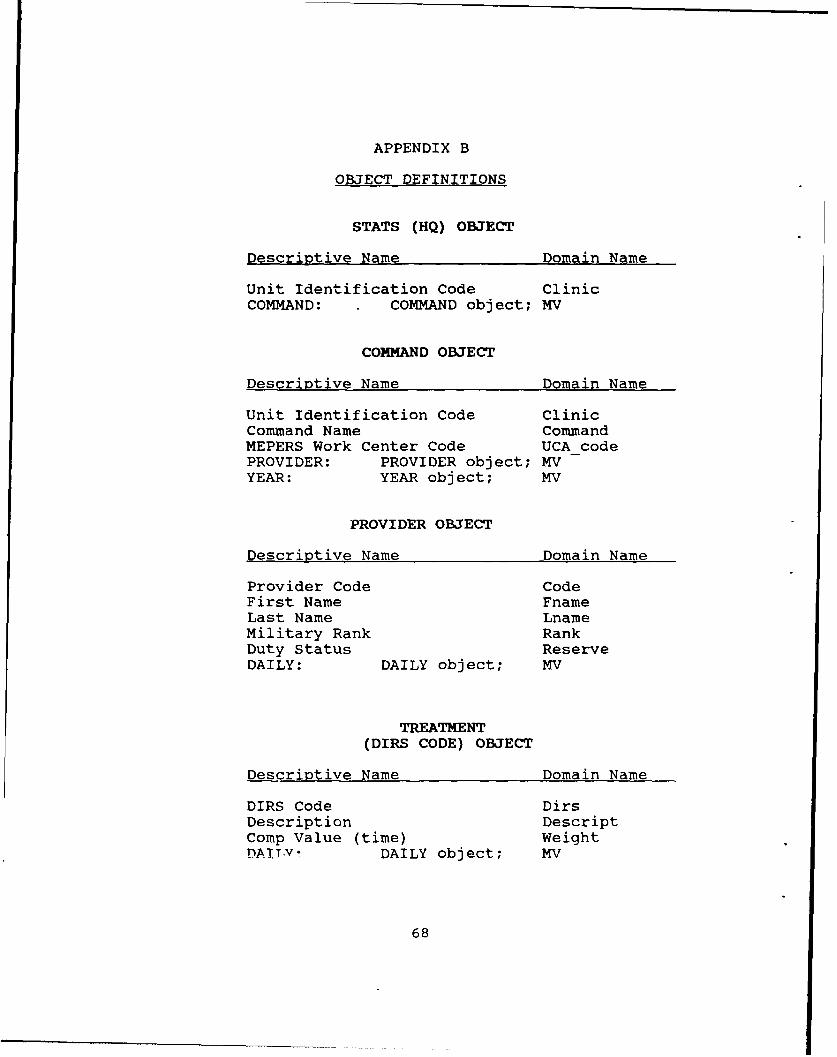
APPENDIX B
OBJECT DEFINITIONS
STATS (HQ) OBJECT
Descriptive Name Domain Name
Unit Identification Code ClinicCOMMAND: COMMAND object; MV
COMMAND OBJECT
Descriptive Name Domain Name
Unit Identification Code ClinicCommand Name CommandMEPERS Work Center Code UCA codePROVIDER: PROVIDER object; MVYEAR: YEAR object; MV
PROVIDER OBJECT
Descriptive Name Domain Name
Provider Code CodeFirst Name FnameLast Name LnameMilitary Rank RankDuty Status ReserveDAILY: DAILY object; MV
TREATMENT
(DIRS CODE) OBJECT
Descriptive Name Domain Name
DIRS Code DirsDescription DescriptComp Value (time) WeightDATT.VI DAILY object; MV
68
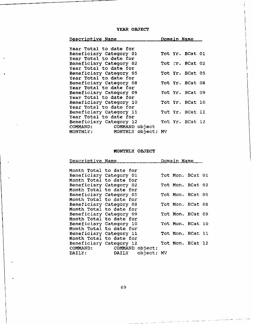
YEAR OBJECT
Descriptive Name Domain Name
Year Total to date forBeneficiary Category 01 Tot Yr. BCat 01Year Total to date forBeneficiary Category 02 Tot Yr. BCat 02Year Total to date forBeneficiary Category 05 Tot Yr. BCat 05Year Total to date forBeneficiary Category 08 Tot Yr. BCat 08Year Total to date forBeneficiary Category 09 Tot Yr. BCat 09Year Total to date forBeneficiary Category 10 Tot Yr. BCat 10Year Total to date forBeneficiary Category 11 Tot Yr. BCat 11Year Total to date forBeneficiary Category 12 Tot Yr. BCat 12COMMAND: COMMAND objectMONTHLY: MONTHLY object; MV
MONTHLY OBJECT
Descriptive Name Domain Name
Month Total to date forBeneficiary Category 01 Tot Mon. BCat 01Month Total to date forBeneficiary Category 02 Tot Mon. BCat 02Month Total to date forBeneficiary Category 05 Tot Mon. BCat 05Month Total to date forBeneficiary Category 08 Tot Mon. BCat 08Month Total to date forBeneficiary Category 09 Tot Mon. BCat 09Month Total to date forBeneficiary Category 10 Tot Mon. BCat 10Month Total to date forBeneficiary Category 11 Tot Mon. BCat 11Month Total to date forBeneficiary Category 12 Tot Mon. BCat 12COMMAND: COMMAND object;DAILY: DAILY object; MV
69
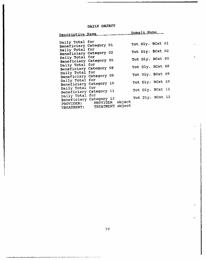
DAILY OBJECT
Descriptive Name Domain Name
Daily Total forBeneficiary Category 01 Tot Dly. BCat 01
Daily Total forBeneficiary Category 02 Tot Dly. BCat 02
Daily Total forBeneficiary Category 05
Tot Dly. BCat 05
Daily Total forBeneficiary Category 08
Tot Dly. BCat 08
Daily Total forBeneficiary Category 09
Tot Dly. BCat 09
Daily Total forBeneficiary Category 10
Tot Dly. BCat 10
Daily Total forBeneficiary Category 11
Tot Dly. BCat 11
Daily Total forBeneficiary Category 12
Tot Dly. BCat 12
PROVIDER: PROVIDER object
TREATMENT: TREATMENT object
70
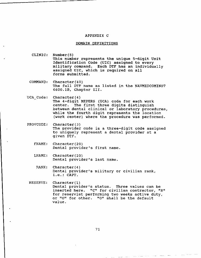
APPENDIX C
DOMAIN DEFINITIONS
CLINIC: Number(5)This number represents the unique 5-digit UnitIdentification Code (UIC) assigned to everymilitary command. Each DTF has an individuallyassigned UIC, which is required on allforms submitted.
COMMAND: Character(40)The full DTF name as listed in the NAVMEDCOMINST6600.1B, Chapter III.
UCA Code: Character(4)The 4-digit MEPERS (UCA) code for each workcenter. The first three digits distinguishbetween dental clinical or laboratory procedures,while the fourth digit represents the location(work center) where the procedure was performed.
PROVCODE: Character(3)The provider code is a three-digit code assignedto uniquely represent a dental provider at agiven DTF.
FNAME: Character(20)Dental provider's first name.
LNAME: Character(20)Dental provider's last name.
RANK: Character(4)Dental provider's military or civilian rank,i.e.; CAPT.
RESERVE: Character(l)Dental provider's status. Three values can beinserted here. "C" for civilian contractor, "R"for reservist performing two weeks active duty,or "0" for other. "0" shall be the defaultvalue.
71
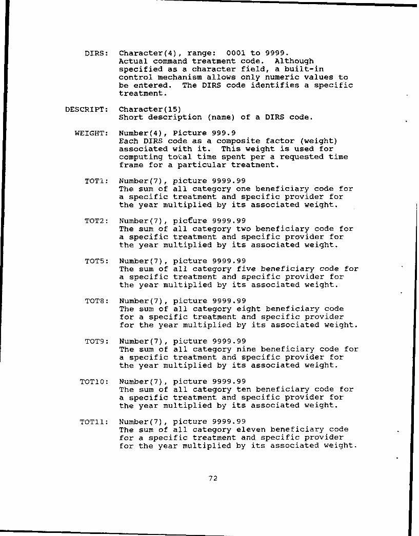
DIRS: Character(4), range: 0001 to 9999.Actual command treatment code. Althoughspecified as a character field, a built-incontrol mechanism allows only numeric values tobe entered. The DIRS code identifies a specifictreatment.
DESCRIPT: Character(15)Short description (name) of a DIRS code.
WEIGHT: Number(4), Picture 999.9Each DIRS code as a composite factor (weight)associated with it. This weight is used forcomputing total time spent per a requested timeframe for a particular treatment.
TOTi: Number(7), picture 9999.99The sum of all category one beneficiary code fora specific treatment and specific provider forthe year multiplied by its associated weight.
TOT2: Number(7), picture 9999.99The sum of all category two beneficiary code fora specific treatment and specific provider forthe year multiplied by its associated weight.
TOT5: Number(7), picture 9999.99The sum of all category five beneficiary code fora specific treatment and specific provider forthe year multiplied by its associated weight.
TOT8: Number(7), picture 9999.99The sum of all category eight beneficiary codefor a specific treatment and specific providerfor the year multiplied by its associated weight.
TOT9: Number(7), picture 9999.99The sum of all category nine beneficiary code fora specific treatment and specific provider forthe year multiplied by its associated weight.
TOT1O: Number(7), picture 9999.99The sum of all category ten beneficiary code fora specific treatment and specific provider forthe year multiplied by its associated weight.
TOT11: Number(7), picture 9999.99The sum of all category eleven beneficiary codefor a specific treatment and specific providerfor the year multiplied by its associated weight.
72

TOT12: Number(7), picture 9999.99The sum of all category twelve beneficiary codefor a specific treatment and specific providerfor the year multiplied by its associated weight.
TOT13: Number(7), picture 9999.99The sum of all category thirteen beneficiary codefor a specific treatment and specific providerfor the year multiplied by its associated weight.
M totl: Number(5), Picture 99999Total number of treatment provided for a specifictreatment by a specific provider for beneficiarycode 1. A cumulative count of D totl domain forthe user's open month selection.
M tot2: Number(5), Picture 99999Total number of treatment provided for a specifictreatment by a specific provider for beneficiarycode 2. A cumulative count of D tot2 domain forthe user's open month selectio".
M tot5: Number(5), Picture 99999Total number of treatment provided for a specifictreatment by a specific provider for beneficiarycode 5. A cumulative count of D tot5 domain forthe user's open month selection.
M tot8: Number(5), Picture 99999Total number of treatment provided for a specifictreatment by a specific provider for beneficiarycode 8. A cumulative count of D tot8 domain forthe user's open month selection.
Mtot9: Number(5), Picture 99999Total number of treatment provided for a specifictreatment by a specific provider for beneficiarycode 9. A cumulative count of D tot9 domain forthe user's open month selection.
M totlO: Number(5), Picture 99999Total number of treatment provided for a specifictreatment by a specific provider for beneficiarycode 10. A cumulative count of D totlO domainfor the user's open month selection.
M totil: Number(5), Picture 99999Total number of treatment provided for a specifictreatment by a specific provider for beneficiarycode 11. A cumulative count of D totll domainfor the user's open month selection.
73

M totl2: Number(5), Picture 99999Total number of treatment provided for a specifictreatment by a specific provider for beneficiarycode 12. A cumulative count of D totl2 domainfor the user's open month selection.
M totl3: Number(5), Picture 99999Total number of treatment provided for a specifictreatment by a specific provider for beneficiarycode 13. A cumulative count of D totl3 domainfor the user's open month selection.
DTOT1: Number(5), Picture 99999Total number.of treatment provided for a specifictreatment by a specific provider for beneficiarycode 1.
DTOT2: Number(5), Picture 99999Total number of treatment provided for a specifictreatment by a specific provider for beneficiarycode 2.
DTOT5: Number(5), Picture 99999Total number of treatment provided for a specifictreatment by a specific provider for beneficiarycode 5.
DTOT8: Number(5), Picture 99999Total number of treatment provided for a specifictreatment by a specific provider for beneficiarycode 8.
DTOT9: Number(5), Picture 99999Total number of treatment provided for a specifictreatment by a specific provider for beneficiarycode 9.
DTOT1O: Number(5), Picture 99999Total number of treatment provided for a specifictreatment by a specific provider for beneficiarycode 10.
D TOT11: Number(5), Picture 99999Total number of treatment provided for a specifictreatment by a specific provider for beneficiarycode 11.
DTOT12: Number(5), Picture 99999Total number of treatment provided for a specifictreatment by a specific provider for beneficiarycode 12.
74

D_TOTI3: Number(5), Picture 99999Total number of treatment provided for a specifictreatment by a specific provider for beneficiarycode 13.
75
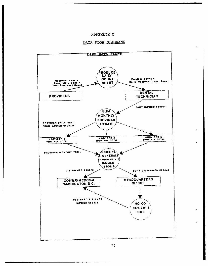
APPENDIX D
DATA FLOW DIAGRAMS
Treatment Code CUTPe~e oe
beneficiary Code *SHEET Daily Tretument Count shoot
Total Treatment Count __
P IDERSDENTALPROVIDERS TECHNICIAN
Sum AirDAILY NNMED 6000111
MONTHLY
PFIOVIDE14 DAILY TOTAL TROTALSRFROM NfMED 6600/11 TTL
PROVIDER I PROVIDER 2 PROVIDER N
P*ONTHLY TOTAL MONTHLY TOTAL MONTHLY TOTAL
PROVIDER MONTHLY TOTAL OMBINGENE RAT
RANCH CLINICNJMED
0600/SDTfF NNUEO 9000/S COPY OF: kNMED 8600/8
COMNAVMEDCOM HEADQUARTERS
W4ASHINGTON D.C. CLINIC
REVIEW A)SIGN /
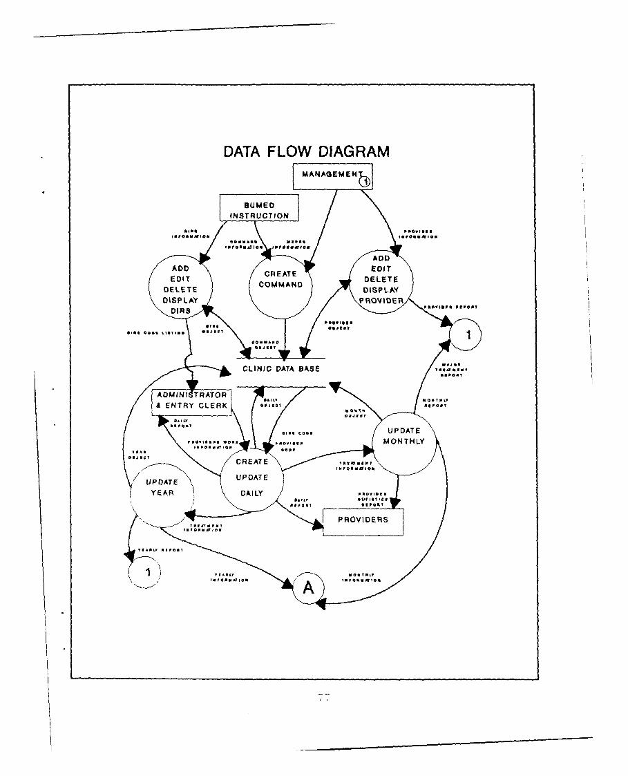
DATA FLOW DIAGRAMMANAGSMEN
)
BUMEDINSTRUCTION
IN ro m,: Mr 10 a IV00 ol V A at latest
MfQM I, AT 004 Impolkallufall
ADDADD CREATE EDITEDIT COMMAND DELETE
DELETE DISPLAXDISPLAY PROVIDER
DIRS V%*Vlbgm
flo'blayslat calls L1671100, esigo?0:: MAN r
Joe?
CLINIC DATA BASE I. We 10, 6% 1msp:MT
ADMIN19TRATOR#A V 01001PO
A ENTRY CLERK 0001101 Me" 0, 70490
0,0: ces, UPDATE
wV-X Irv MONTHLYc
CREATE Tallomflut11frommajoll
Upi)ATE UPDATE
YE R DAILY :ueviolsit,
010,041 PONT
PROVIDERS
VIAML, Moves?
arfammAlle"

HEADQUARTER
MANAGE ME
MANAGEMENTREPORT$
M ON T H LYTEIN FORMAT ION CREATE
UPDAT E
YEARLY STATSIN FORMAT I ON
STATSOBJECT
HO DATA BASE

APPENDIX E
UPDATE, DISPLAY AND CONTROL MECHANISMS
PROVIDER OBJECTUpdate Mechanisms
I. Create PROVIDER
A. Input Description- Provider code assigned by database administrator- Provider name (last and first name)- Rank or rate- Status code (R = reservist, C = contracted
personnel,0 = others that are not R or C)
B. Output Description- New PROVIDER object
C. Processing Notes- System shall check to ensure that no two
providers have the same provider code
D. Volume- Approximately six to ten providers per dental
clinic- Volume is dependent on the size of command
E. Frequency- Created when a new provider checks onboard
II. Modify PROVIDER
A. Input Description- Correction to provider listing- PROVIDER object
B. Output Description- Modified PROVIDER object- Confirmation message while updating on screen
C. Processing Notes- System shall not allow user to modify key field
(provider code)
79

D. Volume- One record correction per quarter
E. Frequency- One record correction per quarter
III. Delete PROVIDER
A. Input Description- Transferred personnel report- PROVIDER object
B. Output Description- updated PROVIDER object- Confirmation message to delete record on screen
C. Processing Notes- Record is displayed for confirmation. User must
respond affirmatively to the prompt to deleterecord
D. Volume- Varies with the number of transfers
E. Frequency- Varies with the number of transfers
PROVIDER OBJECTDisplay Mechanisms
I. PROVIDER listing
A. Output Description- Form showing provider code, first and last name,
rank and status code (R, C, 0)
B. Source data- PROVIDER object
C. Processing Notes- Produce weekly by database administrator
D. Volume- One report per week
E. Frequency- One report per week
80

PROVIDER OBJECTControl Mechanisms
I. Pop-up windows, system validation routines, along withuser prompts
TREATMENT OBJECTUpdate Mechanisms
I. Create TREATMENT
A. Input Description- DIRS treatment codes, description, and Critical
Time Value (CTV) are specified in NAVMEDCOMINST6600.lB
- New code created by Bureau of Medicine (BUDMED)
B. Output Description- New TREATMENT object
C. Processing Notes- System shall ensure that each treatment code is
unique- This table will be created for the user
D. Volume- Approximately three hundred codes
E. Frequency- Once at system development
II. Modify TREATMENT
A. Input Description- Correction to initial entries made during system
implementation- Changes made to NAVMEDCOMINST 6600.1B
B. Output Description- Modified TREATMENT object- Confirmation message while updating on screen
C. Processing Notes- System zhall not allow user to modify key field
(treatment code)
D. Volume
- Extremely low
81

E. Frequency- Approximately once every two years some of the
treatment codes may change or its CTV willchange. These changes are determined at anechelon 2 command level not at an echelon 3 or 4command where this system is designed for use
III. Delete TREATMENT
A. Input Description- Invalid treatment code entered during creation- Outdated treatment codes that have been deleted
in NAVMEDCOMINST 6600.1B
B. Output Description- Updated TREATMENT object- Confirmation message while updating on screen
C. Processing Notes- System shall allow user verification to modify
key- Confirmation message to delete record on screen
D. Volume- Extremely low
E. Frequency- Approximately once every two year some of the
treatment codes may change or its CTV willchange. These changes are determined at anechelon 2 command level not at an echelon 3 or 4command where this system is designed for use
TREATMENT OBJECTDisplay Mechanisms
I. TREATMENT listing
A. Output Description- Form showing treatment (DIRS) code, description,
CTV (weight)
B. Source data- TREATMENT object
C. Processing Notes- This object is used for treatment code
validation while updating the DAILY, MONTHLY,and YEARLY object
82

D. Volume- One report to verify any updates
E. Frequency- One per year
TREATMENT OBJECTControl Mechanisms
I. Pop-up windows, system validation routines, along withuser prompts
DAILY OBJECTUpdate Mechanisms
I. Create Daily
A. Input Description- Month selection (from menu selection options)- Provider selection (from provider object)- Treatment code selection (from treatment object)- Manual data entry of totals for each beneficiary
(category) code treated (from daily providers'work sheet)
B. Output Description- New DAILY object in database- Updated MONTHLY object in database- Updated YEARLY object in database- Confirmation message of updates on screen- Online monthly and yearly totals for selected
treatment and individual provider on screen- On demand Hardcopy availability of input data
for the data entry session
C. Processing Notes- The DAILY object is initialized with each
session, therefore the Daily report will onlyreflect information keyed in during the currentsession
D. Volume- Average number of different treatments per
provider is 26 treatments per day. Each clinicaverages six providers per work-day (Mondaythrough Friday)
83

E. Frequency- Once per day or one per session (when data is
entered). Users have specified that data isentered at minimum once per week
- Minimum one per week
II. Modify DAILY data
A. Input Description- Changes or errors noted on daily providers' work
sheet)- Data entry errors not corrected at initial entry
need to be corrected- Procedure same as with create DAILY except that
negative or positive values are entered tocorrectly adjust the monthly and yearly totalsfor a requested provider, treatment and month
B. Output Description- Modified DAILY object in database- Modified MONTRLY object in database- Updated YEARLY object in database- Confirmation message of updates on screen- Online monthly and yearly totals for selected
treatment and individual provider on screen- On demand Hardcopy availability of input data
for the modification data entry session
C. Processing Notes- The DAILY object is initialized with each new
data entry session, therefore the Daily reportwill only reflect information keyed in duringthis session
D. Volume- One day per month, ten treatments
E. Frequency- As needed- Modification are generally only needed due to
erroneous data entry. Since control mechanismsare built into the system, prompting data entrypersonnel to validate entry before entry isaccepted into the database, these type of errorsare infrequent
84

III. Delete DAILY data
A. Input Description- Procedure same as with create DAILY except that
negative values are entered to correctlyadjust the monthly and yearly totals for arequested provider, treatment and month
- The DAILY cbject is deleted autoratically whenthe system is executed for the first timeduring the day. A new DAILY object reflectingthe new transaction is then generated
B. Output Description- Modified DAILY object in database reflecting
deleted transactions- Updated MONTHLY object in database- Updated YEARLY object in database- Confirmation message of updates on screen- Online monthly and yearly totals for selected
treatment and individual provider on screen- On demand Hardcopy availability of input data
for the modification data entry session
C. Processing Notes- The DAILY object is initialized with each new
data entry session. Therefore the Daily reportwill only reflect information keyed in duringthis session
D. Volume- One to two records per entry session
E. Frequency- As required
DAILY OBJECTDisplay Mechanisms
I. Daily Report
A. Output Description- Form showing by beneficiary codes, and all
treatments, performed by each provider. Thereport shall total the number of treatments fora single treatment code with its associatedcomposite time value total (CTV) (weighted time)total number treatment performed times its CTV)for all active Navy and retired personnel. Theform shall also give a one-line summary of thework performed for each provider. A new page is
85

used for every provider. The command dailysummary shall also be printed on a separatesheet in the same prestated format. SeeAppendix K for an example of the daily summary
B. Source data- DAILY object
C. Processing Notes- Daily object contains PROVIDER, TREATMENT object
data- Use at local command and distributed to each
provider for accuracy validation
D. Volume- One for entry clerk- One copy for each provider- One copy to the administration officer
E. Frequency- One daily or one per data entry session
DAILY OBJECTControl Mechanisms
Pull-down menus, pop-up windows, system validationroutines, along with user prompts
MONTHLY OBJECTUpdate Mechanisms
I. Create Monthly
A. Input Description- DAILY object automatically updates the MONTHLY
object for the selected month
B. Output Description- Updated MONTHLY object in database- Updated YEARLY object in database- Online monthly and yearly totals for selected
treatment and individual provider on screen- On demand Hardcopy availability of work
performed by provider for a selected month
C. Processing Notes- The DAILY object is initialized with each
new session. Therefore the Daily report will
86

only reflect information keyed in during thedata entry sitting
D. Volume- Average number of different treatments per
provider is 26 treatments per day times thenumber of work days per month. Each clinicaverages six providers per work-day (Mondaythrough Friday)
E. Frequency- Since DAILY object automatically updates the
MONTHLY object the frequency is the same as forthe DAILY object update
- Minimum one per week
II. Modify MONTHLY data
A. Input Description- Changes or errors noted on daily providers' work
sheet- Data entry errors not corrected at initial entry
need to be corrected- Procedure same as with create DAILY except that
negative oi positive values are entered tocorrectly adjust the monthly and yearly totalsfor a requested provider, treatment and month
B. Output Description- Modified DAILY object in database- Modified MONTHLY object in database- Updated YEAR object in database- Confirmation message of updates on screen- Online monthly and yearly totals for selected
treatment and individual provider on screen- On demand Hardcopy availability of input data
for the modification data entry session
C. Processing Notes- The MONTHLY object is modified via the update
daily mechanism which updates the DAILY objectas well as the MONTHLY
D. Volume- Number of treatments is dependent on the number
of incorrect daily entries made during a givenmonth. Errors are generally corrected via thevalidated daily provider's report which isreturned to the DIRS data entry clerk
- Low
87

E. Frequency- As required- Modification are generally only needed due to
erroneous data entry. Since control mechanismare built in the system which prompt data entrypersonnel to validate entry before entry isaccepted into the database, these type of errorsare infrequent
III. Delete MONTHLY data
A. Input Description- Procedure same as with update DAILY except that
negative values are entered to correctlyadjust the monthly and yearly totals for arequested provider, treatment and month
- The MONTHLY object is deleted through theutilities option by selecting the start new yearoption
B. Output Description- New database structure created for MONTHLY
object when a new year is started- Updated MONTHLY object in database- Updated YEAR object in database- Confirmation message of updates on screen- Online monthly and yearly totals for selected
treatment and individual provider on screen- On demand Hardcopy availability of input data
for the modification data entry session
C. Processing Notes- MONTHLY object is automatically updated via the
update daily module
D. Volume- Low
E. Frequency- MONTHLY object is deleted once per year
88

MONTHLY OBJECTDisplay Mechanisms
I. Monthly Report
A. Output Description- Same as with Daily object report except that
information represents monthly figures versusdaily totalsProviders' statistical report used by managementdisplays provider code, total number oftreatments, total CTV, and cumulative commandtotals for the selected month. Headquarters mayalso produce similar report provided informationhas been imported from subordinate commandsMajor treatment report allowing user to narrowits scope of information by the selection of upto ten critical treatment codes. List providersalong with treatment codes, total number oftreatments and total CTV
B. Source data- Selected MONTHLY object- May be selected any time during the year for a
requested month
C. Processing Notes- MONTHLY object contains COMMAND and DAILY object
data- Use at local command and distributed to each
provider as a feeder sheet on individualproductivity
- Headquarter maintains an aggregated MONTHLYobject of all its subordinate command to producean OCR monthly report for submission toNAVBUMED, Washington D.C.
- The major treatment report is used by managementfor internal management of providerproductivity
- A monthly report similar in format to themonthly OCR DIRS report produced by HQ. Reportis not OCR font
- A providers statistics report is produceddisplaying information by provider versus bytreatment as in the case of monthly reports
D. Volume- Minimum three per month- Any time during a month for an up-to-date report
89

E. Frequency- Monthly
MONTHLY OBJECTControl Mechanisms
I. Pull-down menus, pop-up windows, system validationroutines, along with user prompts provide suitablecontrol mechanisms
YEAR OBJECTUpdate Mechanisms
I. Create YEAR
A. Input Description- DAILY object automatically updates the YEAR 6
object
B. Output Description- Updated MONTHLY object in database- Updated YEARLY object in database- Online yearly totals for selected
treatment and individual provider on screen
C. Processing Notes- The YEAR object in created at the start of a new
year. The DAILY object is the feeder for theYEAR OBJECT
D. Volume- Average number of different treatments per
provider is 26 treatments per day times thenumber of work days per year. Each clinicaverages six providers per work-day (Mondaythrough Friday)
E. Frequency- As often as the DAILY object is updated
II. Modify YEAR data
A. Input Description- Same as with DAILY and MONTHLY object
90

B. Output Description- Modified YEAR object in database- Confirmation message of updates on screen- Online yearly totals for selected
treatment and individual provider on screen
C. Processing Notes- The YEAR object is modified via the update daily
mechanism which updates the DAILY object as wellas the MONTHLY and YEARLY OBJECT databaseautomatically
D. Volume- Very low since data has generally been corrected
by the DAILY and MONTHLY object updatemechanisms
- Same as per DAILY object
E. Fre(cU'-i
- Same as per DAILY object
III. Delete YEAR data
A. Input Description- Procedure same as with update DAILY except that
negative values are entered to correctlyadjust the yearly totals for a requestedprovider, treatment and month
- The YEAR object is deleted through the utilitiesoption by selecting the start new year option
B. Output Description- New database structure created for the YEAR
object when a new year is started- Updated YEAR object in database- Confirmation message of updates on screen- Online yearly totals for selected
treatment and individual provider on screen
C. Processing Notes- YEAR object is automatically updated via the
update DAILY object mechanism
D. Volume- Very low
E. Frequency- YEAR object is deleted once per year
91

YEAR OBJECTDisDlay Mechanisms
I. Annual Report
A. Output Description- Same as with Monthly report except that
information represents the total number oftreatment to date for the given year
B. Source data- Selected YEAR object
C. Processing Notes- YEAR object contains COMMAND and MONTHLY object
data- Use at local command and distributed to each
provider as a feeder sheet on individualproductivity
- Use by management for planning and budgetingfunction
- Use by management as a verification toolsagainst the aggregated monthly reports
- A providers statistics report is produceddisplaying information by provider versus bytreatment as in the case of a monthly report
D. Volume- One per month- One per year- Any time during the year
E. Frequency- Monthly- Yearly
YEAR OBJECTControl Mechanisms
I. Pull-down menus, pop-up windows, system validationroutines, along with user prompts provide suitablecontrol mechanisms
92
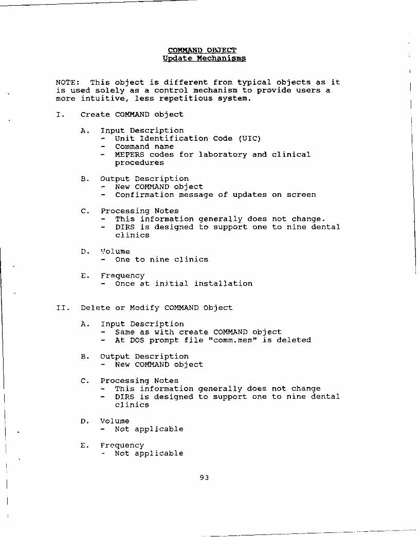
COMMAND OBJECTUpdate Mechanisms
NOTE: This object is different from typical objects as itis used solely as a control mechanism to provide users amore intuitive, less repetitious system.
I. Create COMMAND object
A. Input Description- Unit Identification Code (UIC)- Command name- MEPERS codes for laboratory and clinical
procedures
B. Output Description- New COMMAND object- Confirmation message of updates on screen
C. Processing Notes- This information generally does not change.- DIRS is designed to support one to nine dental
clinics
D. Volume- One to nine clinics
E. Frequency- Once at initial installation
II. Delete or Modify COMMAND Object
A. Input Description- Same as with create COMMAND object- At DOS prompt file "comm.mem" is deleted
B. Output Description- New COMMAND object
C. Processing Notes- This information generally does not change- DIRS is designed to support one to nine dental
clinics
D. Volume- Not applicable
E. Frequency- Not applicable
93

COMMAND OBJECTDisplay Mechanisms
I. Pop-up windows
A. Output Description- Help screens displaying and prompting user for
command or MEPERS selection
B. Source data- COMMAND object (alias comm.mem)
C. Processing Notes- Mainly used at headquarter (HQ) level where user
must differentiate between commands
D. Volume- Anytime HQ wishes to print report on a
particular clinic
E. Frequency- Varies from command to command
COMMAND OBJECTControl Mechanisms
I. Pull-down menus, pop-up windows, system validationroutines, along with user prompts
II. Automatic UIC entry
A. Output Description- Automatically enters command UIC to file that
will be exported to HQ
B. Source Data- COMMAND .bject
C. Processing Notes- User never has to key-in command information for
updating DAILY, MONTHLY, or YEARLY object thusavoiding possible data validity and data entryerrors
D. Volume- Same as with DAILY object update mechanisms
94

E. Frequency- Daily
STATS OBJECTUpdate Mechanisms
I. Create STATS
A. Input Description- An aggregate of all data segregated by month for
an entire year on all subordinate commands- This object is only maintained at HQ- Created by impoiting subordinate command MONTHLY
object
B. Output Description- Updated STATS object at HQ
C. Processing Notes- This object is the major feeder for all reports
that are generated by HQ
D. Volume- MONTHLY object for each subordinate clinic- Approximately 156 records per clinic
E. Frequency- Created once per Year
II. Modify STATS data
A. Input Description- Monthly Import file from subordinate command
B. Output Description- Updated STATS object at HQ
C. Processing Notes- Automatically modified with import of
subordinate command
D. Volume- One to two records per month per clinic
E. Frequency- Once per month
95
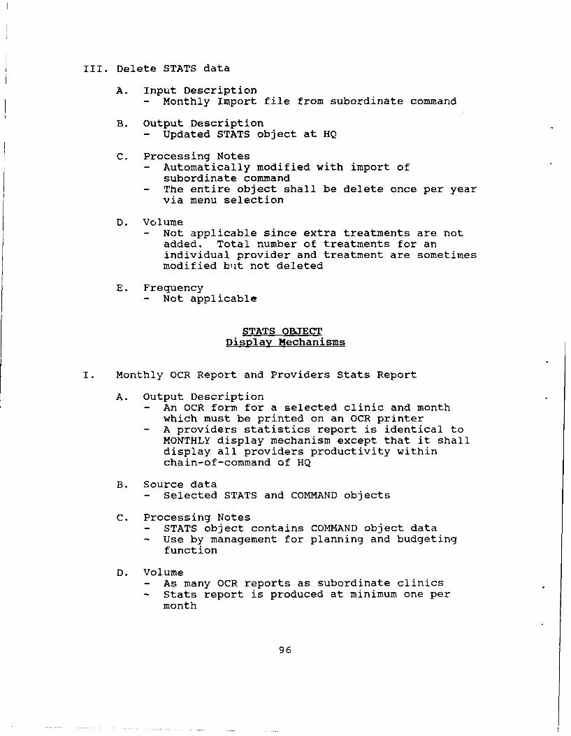
III. Delete STATS data
A. Input Description
- Monthly Import file from subordinate command
B. Output Description- Updated STATS object at HQ
C. Processing Notes- Automatically modified with import of
subordinate command- The entire object shall be delete once per year
via menu selection
D. Volume- Not applicable since extra treatments are not
added. Total number of treatments for anindividual provider and treatment are sometimesmodified but not deleted
E. Frequency- Not applicable
STATS OBJECTDisplay Mechanisms
I. Monthly OCR Report and Providers Stats Report
A. Output Description- An OCR form for a selected clinic and month
which must be printed on an OCR printer- A providers statistics report is identical to
MONTHLY display mechanism except that it shalldisplay all providers productivity withinchain-of-command of HQ
B. Source data- Selected STATS and COMMAND objects
C. Processing Notes- STATS object contains COMMAND object data- Use by management for planning and budgeting
function
D. Volume- As many OCR reports as subordinate clinics- Stats report is produced at minimum one per
month
96
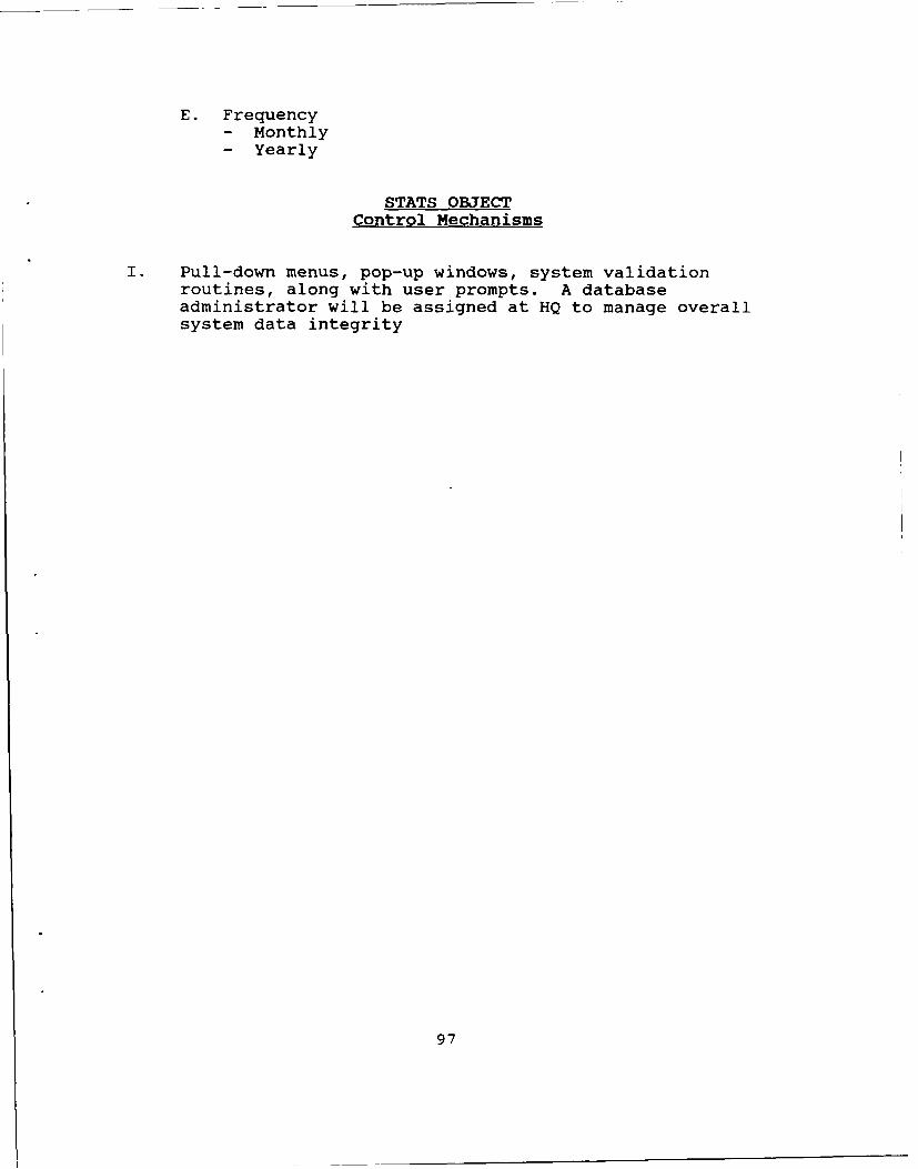
E. Frequency- Monthly- Yearly
STATS OBJECTControl Mechanisms
I. Pull-down menus, pop-up windows, system validationroutines, along with user prompts. A databaseadministrator will be assigned at HQ to manage overallsystem data integrity
97
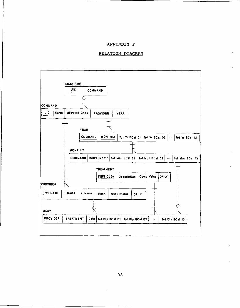
APPENDIX F
RELATION DIAGRAM
8TA7T8 (HO0)
UIO COMMAND
COMMAND
UIc N ame MEPERS Code PROVIDER YA
YEAR jCSOMMAND IMONTHLY Tot Yr BCmt 01 Tot Yr ICat 02 Tot Yr ECat 13
MONTHLY
COMMAND DAILYjMonthjTot Mon BCat 01 Tot Mon BCat02 .. Tot Man BCat 13
TREATMENT
DIRS Cod. Description Comp Value DAY
PROVIDER T
DAILY
PROVIDER TREATMENT Date Tot Dly ECat 01 1Tot Dly BCat 02 Tot Oly ECat 1
98

APPENDIX G
LOGICAL MENU STRUCTURE
MENU HIERARCHY
ASSI
Svivo
lm L
ILITI! OELII ANNUAL 1111t so
SIR PROVIOIN REPORT NEW TIAN 111polly
LIST LIST PSOVISCI TmAN8FImIS PIOTISIES :No MAI to list,.YE
IEIMUESTOC REPR [, ORT~m
AJmum
99

APPENDIX II
SAMPLE REPORTS
NAVAL DENTAL CLINIC, LONG BEACH, CA. 12:49:38 01/13/90DENTAL INFORMATION RETRIEVAL SYSTEM SCREEN # 1.4
REPORT MENU
DAILY REPORTMONTHLY REPORTANNUAL REPORTPROVIDERS STATS.MAJOR TREATMENT REPORT
RETURN TO MAIN MENU
USE UP AND DOWN CURSOR KEYS T1 TO HIGHLIGHT ITEM ANDPRESS<RETURN>
Branch Clinic Report Menu
Documents on the following pages of this appendix depict
sample reports produced after selection of menu options
presented from the DIRS Branch Clinic Report Menu screen
reproduced above.
100

02/05/90PAGE 1
DENTAL INFORMATION RETRIEVAL SYSTEMDAILY INPUT REPORT
PROVIDER: 117
BENEFICIARY CATEGORY CTV CTV CTV01 02 05 08 09 10 11 12 13 TOTAL TOTAL NAVY RETIRED
TREATMENT CODE: 0001 **5.0 0.0 2.0 3.0 22.0 33.0 0.0 0.0 1.0 66.0 132.C 10.0 0.0
" TREATMENT CODE: 5752 **
3.0 0.0 0.0 3.0 34.0 0.0 33.0 0.0 9.0 82.0 344.4 12.6 138.6
PROVIDER TOTALSBENEFICIARY CATEGORY CTV CTV CTV
01 02 05 08 09 10 11 12 13 TOTAL TOTAL NAVY RETIRED
8.0 0.0 2.0 6.0 56.0 33.0 33.0 0.0 10.0 148.0 476.4 22.6 138.6
101

02/05/90PAGE 2
DENTAL INFORMATION RETRIEVAL SYSTEMDAILY INPUT REPORT
TOTALS FOR TCDAYBENEFICIARY CATEGORY CTV CTV CTV
01 02 05 08 09 10 11 12 13 TOTAL TOTAL NAVY RETIRED8.0 0.0 2.0 6.0 56.0 33.0 33.0 0.0 10.0 148.0 476.4 22.6 138.6
102

Page No. 102/ 05/ 90
DENTAL INFORMATIONRETRIEVAL SYSTEMTREATMENT REPORT
FOR THE MONTH OF JUNE
CTV CTV CTVCT01 CT02 CT05 CT08 CT09 CTIO CT11 CT12 CT13 TOTAL TOTAL NAVY RET.
'* DIRS 0001
' Subtotal *36 0 0 0 0 0 0 0 0 36 12.0 72.0 0.0
** DIRS 0002
Subtotal *7 0 0 0 0 0 0 0 0 7 28.0 28.0 0.0
DIRS 0003
' Subtotal ''
5 0 0 0 0 0. 0 0 0 5 25.0 25.0 0.0
DIRS 0004
" Subtotal **12 0 0 0 0 0 0 0 0 12 48.0 48.0 0.0
DIRS 0005
Subtotal ,,1 0 0 0 0 0 0 0 0 1 5.0 5.0 0.0
** DIRS 2306
** Subtotal **
26 0 0 0 0 0 0 0 0 26 26.0 26.0 0.0
DIRS 0007
** Subtotal ''
1 0 0 0 0 0 0 0 0 1 2.0 2.0 0.0
DIRS 0010
** Subtotal ,18 0 0 0 0 0 0 0 0 18 90.0 90.0 0.0
DIRS 0011
*' Subtotal "37 0 0 0 0 0 0 0 0 37 74.0 74.0 0.0
103

Page No. 1102/05/90
DENTAL INFORMATIONRETRIEVAL SYSTEMTREATMENT REPORT
FOR THE MONTH OF JUNE
CTV CTV CTV
CT01 CT02 CT05 CT08 CT09 CTI0 CT11 CT12 CT13 TOTAL TOTAL NAVY RET.
DIRS 9918Subtotal **
38 0 1 0 0 0 4 0 0 43 21.5 19.0 2.0
** DIRS 9923
** Subtotal ''
27 1 6 0 0 1 1 0 0 36 28.8 21.6 0.8
** DIRS 9972
* Subtotal **512 4 17 0 20 4 20 6 6 589 471.2 409.6 16.0
** DIRS 9973
** Subtotal *"346 0 17 0 8 8 23 3 0 405 445.5 380.6 25.3
*t* Total ***
5583 21 200 1 121 56 231 30 22 6265 5221.8 4721.3 153.6
104
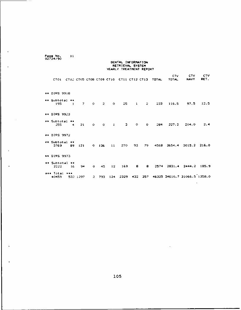
Page No. it02 /24/90
DENTAL INFORMATION
RETRIEVAL SYSTEMYEARLY TREATMENT REPORT
CTV CTV CTVCTO1 CT02 CT05 CT08 CT09 CTIO CTI1 CT12 CT13 TOTAL TOTAL NAVY RET.
DIRS 9918
** Subtotal 4*
195 1 7 0 2 0 25 1 2 233 116.5 97.5 12.5
4. DIRS 9923
4* Subtotal *4255 4 21 0 0 1 3 0 0 284 227.2 204.0 2.4
** DIPS 9972
4* Subtotal *.3769 89 121 0 136 11 270 93 79 4568 3654.4 3015.2 216.0
.* DIRS 9973
44 Subtotal 4*
2222 16 94 0 45 12 169 8 8 2574 2831.4 2444.2 185.9
**# Total ***
40459 532 1297 2 793 124 2329 432 357 46325 34610.7 31066.5 1358.0
105

NAVAL POSTGRADUATE SCHOOL, MONTEREY, CA.Page No: 1
PROVIDER SUMMARY REPORTFOR THE MONTH OF JUN 1990
PROVIDER CODE TOTAL TREATMENT TOTAL VALUE
112 45 25.3
113 841 602.6
114 525 356.0
117 1085 759.2
119 756 436.7
126 532 349.9
131 1127 811.8
132 351 182.8
133 210 1098.0
425 793 599.5
CUMULATIVE TOTALS: 6265 5221.8
106

PAGE:MAJOR TREATMENT REPORTFOR THE MONTH OF JUNE
PROVIDER TREATMENT CODES / WEIGHTED VALUES
0001 0002 9918 9923 9972112 1/ 2.0 0/ 0.0 0/ 0.0 0/ 0.0 7/ 5.6113 0/ 0.0 0/ 0.0 9/ 4.5 14/ 11.2 114/ 91.2114 0/ 0.0 0/ 0.0 5/ 2.5 4/ 3.2 60/ 48.0117 0/ 0.0 0/ 0.0 5/ 2.5 9/ 7.2 87/ 69.6119 0/ 0.0 0/ 0.0 3/ 1.5 9/ 7.2 31/ 24.8126 1/ 2.0 0/ 0.0 4/ 2.0 0/ 0.0 29/ 23.2131 0/ 0.0 0/ 0.0 0/ 0.0 0/ 0.0 113/ 90.4132 0/ 0.0 0/ 0.0 0/ 0.0 0/ 0.0 148/118.4133 34/ 68.0 7/ 28.0 0/ 0.0 0/ 0.0 0/ 0.0425 0/ 0.0 0/ 0.0 17/ 8.5 0/ 0.0 0/ 0.0
107

APPENDIX I
NAVMUD FORM 6600/11
The document presented on the following two pages is an
excerpt from NAVMEDCOMINST 6600 1B
108

DENTAL INFORMATION RETRIEVAL SYIEM
O(WTAL INFORMATION INDIVIDUAL DAILY TREATMENT RECORD NAVUEDCOMINST 46M.1RETAIEVAL SYSYITM
ONO. VIO JAL DAILYR[ATMINT RECORD
TIME PATIENT'S NAME AN0 SSN RANK TREATMENT CLASSTIMEOA FUNCTION- GiEN CAT
0730/ BU), CUSTER BM3 N15 MOL AM, BASE, l.D., OHI, ANI.S I08 2 I5 S- 23-X970 (01)
0.430/ IIANLJS, ROBERI'l MA.J PERIO SCL AND ROOT PLANE x 2 SEXTANTS, 0111, 2OSSS ?36-SS-9990 (05) ANES x 2
0900/ RUSSEI.I., CRAIG CAPT/ PRO, SCL x 2 SEXTANTS, OHI, SNF2092S 467-98-010S RET(II)
0930/ NFAIAN, (UY D/S 93 DF AM, R.D.. SNF2, ANES102S 335-89-4736 (13)
1030/ BROWN, GRACE LT T-2 EXAM, PLAQUE INDEX, OHI, PERIO SCL AND1125 163-52-2019 (01) ROOT PLANE x I SEXTANT, PHOTO, BP 3
1130/ INSERVICE TRAINING1230 "OI)E BLUE"
1230/ LUNCH1330
1330/ LOW, HENRY -941 ENDO INT TX, PA, R.D., TEMP 3140S 241-66-9009 (01)
1415/ HOUSEHOLDER, JIM PN2 T-3 EXAM, PANO, 816 IMP EXT, ANES x 2,
1530 3S4-00-S997 (01) RX x 2, BP x 2 3
I1530/ CREDENTIALING COMMITTEE1630 MEETING
OATE NAME AN0 GRA0E SIG4ATURE
12JUN86 0. L. MISS, CAPT, DC, USN09
109

USC FACt IRy38677 NDC OXFORD
TREATMENT _ENEFICIARY CATEGORY TOTAL
cooE 01 O5 11 " 13
0120
0133
0160 3
0220
0330 1
0360
1110
1240 1 1
1330 2 113t0 1 1 ._ __ _ _
2150
2160 1i P__ ___ _______
2940 1
2954
2960 1 2
3360 1
4342 2
7130 ,1 I9211 4 1
9631 - 2- ____
9973 14 1 1 1
•, aWORK HOURS AVAILABLECOLLATERAL LEAVEI OPERATIONAL OTHER OENTAL 7REA7MEN7
OUTIES ILLNESS SUPPORT FUNCTIONS
110

APPENDIX J
NAVMD FORM 6600/8
The document presented on the following page is an excerpt
from NAVMEDCOMINST 6600.1B
111

DENAL INFORMATION TOO$ FORiM MIST 66E PNOPAARED AMDOT"ARETRIEVAL SYSTEM 116340 AN OCm-A TYPING GLEMWN REOR 9WM0TREATMENT REPORT 10 PITCH yeltTnSTIGMDGW
CLAINDCATIS. OF 81M WMI
0009[s] m ii i:m iz
ci] ~ ~ -EXHi]I m2-1i ci c
112iii

APPENDIX K
DENTAL INFORMATIONRETRIEVAL SYSTEM
DIRS
USER'S MANUAL
TABLE OF CONTENTS
SECTION I. INTRODUCTION Page(s)1. Purpose of the User's Manual 1142. Project Reference 1143. Security and Privacy 1144. System Overview 1145. System Responsibility 1146. System Configvration 1157. Hardware Requirements 115
SECTION II. SYSTEM INSTALLATION1. DIRS installation 1152. Loading Command Information File 115-73. Command Information File Correction 1174. Loading Essential Files 117
SECTION III. OPERATION PROCEDURES1. Start-up Procedures 1172. Operating Procedures 117
SECTION IV. MAIN MENU & SUB MENUS1. Main Menu 1202. Input Dirs Data 120-263. Change DIRS Codes 1264. Update Provider Codes 126-275. Reports Menu 1286. Files Utilities 128-307. Headquarters only 131-338. Quit 133
113

SECTION I. INTRODUCTION
1. PURPOSE OF THE USER'S MANUALThe purpose of this User's Guide is to provide
guidelines for personnel using this Dental InformationRetrieval System (DIRS) program. This user's manual shouldanswer most questions concerning the operation of DIRS.Please take time to read this manual carefully. Reading themanual before installation may save you a lot of frustrationand time later on.
2. PROJECT REFERENCESThis guide is divided into sections, depending on the
operation being performed. Material is presented in a stepby step fashion. It is designed to provide timely referenceto aid in resolving most problems that may occur while usingDIRS.
3. SECURITY AND PRIVACYThe DIRS system's databases are unclassified; therefore
no security clearance is required to gain access. However,be informed that each command must have an Automatic DataProcessing Security Plan (ADPSP). It may be advisable tosecure all spaces that contain Personal Computers (PC).Securing PCs also means protecting data from unauthorizedpersonnel that could willingly or accidently destroy datastored on PC.
4. SYSTEM OVERVIEWThe DIRS system is designed to gather accurate
information in a relatively quick time frame. It willreplace the slow and tedious manual process of producing themonthly DIRS report. The system will also maintainproduction data on dental officers providing dentalservices, and other support staff. The DIRS system is amenu-driven data base system prepared as a graduate levelthesis project by two students at the Naval PostgraduateSchool, Monterey, Ca. DIRS is designed so that even non-computer personnel should be able to operate the systemwithout too much difficulty (reading the user's manual willhelp).
5. SYSTEM RESPONSIBILITYThe Dental Department has custody of the DIRS system
and will ensure that all files are properly maintained andkept current. The use of this system is restricted topersonnel who are trained on the IBM PCs (or compatibles) inaccordance with current instructions and those specificallyauthorized in writing by the Head, Dental Department.Furthermore, program modification shall be theresponsibility of custodial command.
114

6. SYSTEM CONFIGURATIONThe DIRS system is simple to use and does not rpquire
complicated ADP equipment. The system's command files arecompiled; meaning, dBASE III PLUS does not have to beinstalled on your PC. It is designed to work on any IBMcompatible PC. Reports are produced using a near-letterquality printer, except for the DIRS reports thatheadquarters produce. An OCR scanner is used to read theDIRS report after it is printed; therefore, an OCR printheadmust be used. It is a requirement that the printer willaccept this type of printhead. The DIRS system will promptthe user to switch to the OCR (auxiliary) printer whencalling the monthly DIRS Report. Remember to switch back toyour primary printer after c6mpleting your OCR report.
7. HARDWARE REQUIREMENTS
a. IBM-PC compatible computer w/640K memory.
b. 20 megabyte hard disk.
c. MS-DOS version 3.0 or higher.
d. An OCR 10 pitch daisy wheel printer.
SECTION II. SYSTEM INSTALLATION
1. DIRS INSTALLATION.Insert disk #1 in drive A:. From the root directory,
at the C: drive DOS prompt, type "A:install." The installprogram will prompt the user for a directory name where DIRSis to be installed. Enter up to ten characters. Theinstall program will create a directory and copy thenecessary files to that directory. The install program willthen ask the user to insert floppy #2 in drive a:, please doso at that time. When installation is completed, a messagewill appear on screen indicating that installation iscomplete. Notice that you are in the newly createddirectory where DIRS has been installed.
2. LOADING COMMAND INFORMATION FILETo run DIRS, type "DIRS" in the directory where DIRS
has been installed. Several screens will appear promptingthe user for vital system and command information. Thescreens presented below are similar to those that the userwill see.
As you are operating the program, you will be directedby the 'COMMAND NAME' and 'SYSTEM NAME' prompts to enter thename of your command and title your DIRS. We recommend thatyou title the system 'DENTAL INFORMATION RETRIEVAL SYSTEM'since that is the function of the system. Keep in mind that
115

fields A and B are used to title the upper left corner ofall the menus presented in DIRS. See Figure (1) for anexample of screen heading (upper left corner). In a sense,you, the user are actually customizing the system to fityour personal taste and requirements. Field C is simply aprompt requesting the number of clinics that will besupported by your command. For example, if you are a branchclinic, ship, or a stand-alone independent clinic, enterone. On the other hand, a headquarters command which willbe requesting information from its subordinate clinicsshould enter the number of subordinate clinics and itself asthe correct number to be supported.
If an error as been made in the data entered, field Dwill allow the user to reenter the data by entering an 'N'(No), in that field. Answering 'Y' (Yes), will generateanother screen prompting you with fields (E-G). Enter yourcommand Unit Identification Code (UIC) in Fields E. Notethat field E will only tolerate numeric values to beentered. Leave a space then insert a dash (-) followed byanother space before entering the official command name. Itis important that the official command be entered correctlysince what you input in this field is the exact data to beoutput on several reports generated by DIRS. Fields F&G arethe UCA codes presently associated with your DIRS reportingprocedure. Again the system will prompt to see if data iscorrect. Answering 'N' (No) to this prompt will allowcorrection to be made. Note that it does not matter whetheryour data is entered in upper or lower case, DIRS willdefault to upper case.
(Initial setup screen #1)
"The following information should only be entered once.DIRS will remember the information that you are aboutto enter. If unsure of what you must enter, see theuser's manual. PLEASE ANSWER THE FOLLOWING:"
COMMAND NAME: (Field A)SYSTEM NAME: (Field B)
"HOW MANY CLINICS WILL DIRS BE SUPPORTING (1-9):" (Field C)
"DATA CORRECT (Y/N)?" (Field D)
116
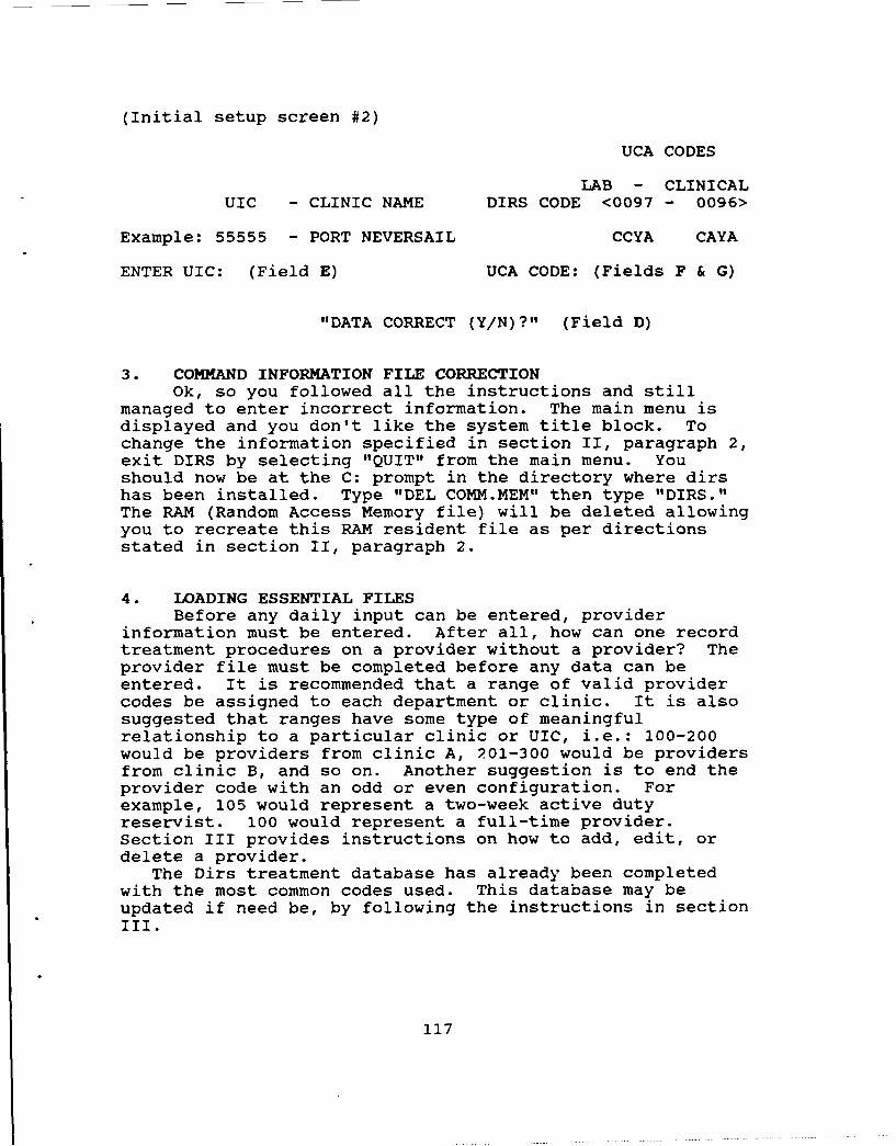
(Initial setup screen #2)
UCA CODES
LAB - CLINICALUIC - CLINIC NAME DIRS CODE <0097 - 0096>
Example: 55555 - PORT NEVERSAIL CCYA CAYA
ENTER UIC: (Field E) UCA CODE: (Fields F & G)
"DATA CORRECT (Y/N)?" (Field D)
3. COMMAND INFORMATION FILE CORRECTIONOk, so you followed all the instructions and still
managed to enter incorrect information. The main menu isdisplayed and you don't like the system title block. Tochange the information specified in section II, paragraph 2,exit DIRS by selecting "QUIT" from the main menu. Youshould now be at the C: prompt in the directory where dirshas been installed. Type "DEL COMM.MEM" then type "DIRS."The RAM (Random Access Memory file) will be deleted allowingyou to recreate this RAM resident file as per directionsstated in section II, paragraph 2.
4. LOADING ESSENTIAL FILESBefore any daily input can be entered, provider
information must be entered. After all, how can one recordtreatment procedures on a provider without a provider? Theprovider file must be completed before any data can beentered. It is recommended that a range of valid providercodes be assigned to each department or clinic. It is alsosuggested that ranges have some type of meaningfulrelationship to a particular clinic or UIC, i.e.: 100-200would be providers from clinic A, 201-300 would be providersfrom clinic B, and so on. Another suggestion is to end theprovider code with an odd or even configuration. Forexample, 105 would represent a two-week active dutyreservist. 100 would represent a full-time provider.Section III provides instructions on how to add, edit, ordelete a provider.
The Dirs treatment database has already been completedwith the most common codes used. This database may beupdated if need be, by following the instructions in sectionIII.
117

SECTION III. OPERATION PROCEDURES
1. START-UP PROCEDURESThe start-up procedure is designed for those with
absolutely no computer background. Those of you with basic"DOS" and PC knowledge may choose to overlook this briefparagraph.
Turn on your computer. Now that your computer is on,check to see if your peripheral devices are on (printers,power director, display terminal, etc.). When everything isturned on, change directories to the directory that containsDIRS. This can be achieved by typing "CD\directory name"where "directory name" is the name that you have selected tolabel your directory. Now type "DIRS," this command willbring up the main menu or the memory screen discussed inSection II, if it has not already been loaded.
2. OPERATION PROCEDURSUsing this system is simply a matter of doing what the
computer tells you to do. Your DIRS system is fully menudriven. Menu driven means that you can select any optionfrom the menu by simply moving the arrows (ti) until youhave highlighted your desired selection. You can alsoselect an option by pressing the first letter of the desiredoption, but in the event that two menu items start with thesame letter, the system will default to the first selection.The most complicated thing about this system is getting overthe phobia generally associated with computers. Remember torelax and read what the computer is prompting you to do.Reading prompts (the messages that the system displays whenit wants you to do something) is generally the key tosuccess when using any menu driven system.
SECTION IV. MAIN MENU AND SUB MENU.
The diagram provided on the next page titled; "MenuHierarchy," should provide a helpful overview of the variousmenu screens availdble in DIRS should you get lost in aparticular level or just want a ready reference to adestination or operation of choice. You may find it helpfulto enlarge the diagram and post it in a convenient locationuntil you gain familiarity with the system.
1I8

MENU HIERARCHY
All I go I @A I les I "ol ielms mim alt lm pIIeuamam smII
ll diDS lIW IlilIl MIOIETmli P lmrllrI Ilt,@IT mm mutI PILIEC
mime 1eollr.*a +01+11'EC liP01a
IIII P11 lljllllt lil SIIIOIIl
SImI FlIllIII IlImII Iii 'TUff lIPO31h
LIII Ll'r NI01lll Il9i1
.&os am I Oist, MI'Ii liMT Lpeal. SO.:OSTS
ows
(so 61111
119

1. THE MAIN MENUHeading
A NAVAL DENTAL CLINIC, USN 13:17:17 01/13/90
DENTAL INFORMATION RETRIEVAL SYSTEM SCREEN # 1.0
MAIN MENU
INPUT DIRS DATACHANGE DIRS CODES
B UPDATE PROVIDER CODESQUERIESFILE UTILITIESHEADQUARTERS ONLYQUIT
C USE UP AND DOWN CURSOR KEYS t4 TO HIGHLIGHT ITEM AND
PRESS<RETURN>
Prompt & Status Box
Figure 1. Main Menu Screen
To operate the DIRS system, enter the first letterwhich corresponds to the item in the menu body that you wantto select, or move the arrow keys (tU) to highlight yourchoice. All menus have a RETURN option to return to thecalling Menu. Note that the heading section of the menuabove, displays the command name and system title that youhave selected and entered at initial installation. Theupper right corner of the menu displays such information ascurrent date, time, and screen number. All menus withinDIRS support this type of display. The body or middle ofthe screen displays options available. The option may beselected as per stated in the bottom section of the screen.This bottom section is the area that the user should payparticular attention to, since error messages and/or userprompts will be displayed there. The system will also beepwhen invalid or incorrect data has been input.
2. INPUT DIRS DATAThe first screen that will appear when selecting option
one (INPUT DIRS DATA) is displayed below (Figure 2). Enter"Y" (yes), if the displayed month is the desired month fordata entry. Enter "N" (no) to select another month. When"N" is selected a window will appear displaying options thatmay be keyed in at the prompt (see Figure 3). The default
month (open month on screen) is the current calendar month
120

month (open month on screen) is the current calendar monthbased on the computers system clock.
NAVAL DENTAL CLINIC, USN 08:05:14 01/13/90DENTAL INFORMATION RETRIEVAL SYSTEM SCREEN # 1.1.1
OPEN MONTH IS JANUARY
IS THIS CORRECT? Y/N
Figure 2. Input DIRS Data (Open Month Confirmation)
NAVAL DENTAL CLINIC, USN 09:02:20 01/13/90DENTAL INFORMATION RETRIEVAL SYSTEM SCREEN # 1.1.1
JAN JULFEB AUGMAR SEPAPR OCTMAY NOVJUN DEC
ENTER THREE LETTERS OF NEW MONTH:
Figure 3. Month Input Screen
To select the correct month, the three letterabbreviation is entered at the prompt. For example, typingJUN in the month selection screen will the month of June fordata entry. Once the desired month has been opened, theprovider prompt screen will follow.
To select a provider, the provider code may be entereddirectly if the code is known, or by pressing the <HOME>key, an additional window with the valid provider codesassigned to the reporting command will pop up. From theavailable valid provider codes on screen, the correspondingnumber that matches the desired provider code may beentered. (See Figures (4) & (5)).
121

NAVAL DENTAL CLINIC, USN 08:18:58 01/13/90
DENTAL INFORMATION RETRIEVAL SYSTEM SCREEN # 1.1.1
PROVIDER CODE:
ENTER PROVIDER CODE OR PRESS <HOME> FOR HELP
Figure 4. Provider Code Entry Screen
NAVAL DENTAL CLINIC, USN 08:18:58 01/13/90DENTAL INFORMATION RETRIEVAL SYSTEM SCREEN # 1.1.1
PROVIDER CODE RANK NAME
1. 100 CDR NAVY, JOSEPH2. 200 LT NAVY, SON3. 300 LT MESIAL, DECAY4. 400 CAPT TOOTH, DECAY5. 455 LT RESERVE, DENTIST6. 500 CDR BUCKLE, PIT7. 600 LT LINGUAL, DISTAL8. 700 ADM DENTAL, SERVICE
PRESS NUMBER OF ITEM, RETURN TO CONTINUE, OR "Q" TO QUIT
Figure 5. Provider Codes Screen
To select a valid provider, enter the matching numberin the leftmost column, i.e.: entering number "1" wouldselect provider 100; CDR Navy. The provider code may alsobe entered directly on the provider input screen. Thismethod of provider data entry provides a method to check theprovider code file to validate a correct provider code forthe reporting unit. Entering an erroneous code (a code notcurrently in the provider code file) results in an errormessage indicating that fact, and further prompts the userto enter another code. When the provider field is correctlyentered, the screen displayed in Figure 6 will follow,prompting the user to enter a valid treatment code. Aspreviously discussed, to escape the DIRS entry routine,press <RETURN> at a blank DIRS field. The "ESC" key providesanother escape route by allowing the user to select the
122
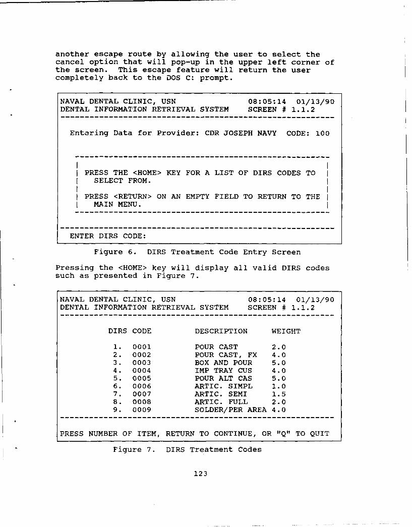
another escape route by allowing the user to select thecancel option that will pop-up in the upper left corner ofthe screen. This escape feature will return the usercompletely back to the DOS C: prompt.
NAVAL DENTAL CLINIC, USN 08:05:14 01/13/90DENTAL INFORMATION RETRIEVAL SYSTEM SCREEN # 1.1.2
Entering Data for Provider: CDR JOSEPH NAVY CODE: 100
PRESS THE <HOME> KEY FOR A LIST OF DIRS CODES TOSELECT FROM.
PRESS <RETURN> ON AN EMPTY FIELD TO RETURN TO THEMAIN MENU.
ENTER DIRS CODE:
Figure 6. DIRS Treatment Code Entry Screen
Pressing the <HOME> key will display all valid DIRS codessuch as presented in Figure 7.
NAVAL DENTAL CLINIC, USN 08:05:14 01/13/90DENTAL INFORMATION RETRIEVAL SYSTEM SCREEN # 1.1.2
DIRS CODE DESCRIPTION WEIGHT
1. 0001 POUR CAST 2.02. 0002 POUR CAST, FX 4.03. 0003 BOX AND POUR 5.04. 0004 IMP TRAY CUS 4.05. 0005 POUR ALT CAS 5.06. 0006 ARTIC. SIMPL 1.07. 0007 ARTIC. SEMI 1.58. 0008 ARTIC. FULL 2.09. 0009 SOLDER/PER AREA 4.0
PRESS NUMBER OF ITEM, RETURN TO CONTINUE, OR "Q" TO QUIT
Figure 7. DIRS Treatment Codes
123

The DIRS treatment code may also be entered directly onthe DIRS prompt screen or the <HOME> key may be used toassist the user in the event that the correct DIRS code isunknown. This help function is not a mandatory inputprocedure, if you know the correct code, entering itdirectly will save time.
To select a DIRS treatment code, the correspondingnumber displayed in the leftmost column is selected bytyping the appropriate number ("1"-"9"). Pressing the <PageDown> or <Page Up> keys will scroll through the list todisplay other treatment codes.
After a valid provider and treatment code have beenselected the following screen (Figure 8) will appear:
NAVAL DENTAL CLINIC, USN 12:04:39 01/13/90DENTAL INFORMATION RETRIEVAL SYSTEM SCREEN # 1.1.3
Entering Data for Provider: TEST TEST TEST CODE: 100DIRS Code: 0120
Additions Totals YearBeneficiaries to File in File to Date
Category 1 0 0 0Category 2 0 0 0Category 5 0 0 0Category 8 0 0 0Category 9 0 0 0Category 10 0 0 0Category 11 0 0 0Category 12 0 0 0Category 13 0 0 0
ENTER NEW VALUES AND PRESS RETURN
Figure 8. DIRS Data Entry Screen
Data entry for an individual provider is accomplishedusing screen 1.1.3, (depicted in Figure 8) by entering thecorrect quantity of procedures completed in each dentalbeneficiary category. A listing with a brief definition ofeach beneficiary category code is provided in the diagram onthe next page.
The <RETURN> key is used to move the cursor to the nextfield for data entry. The steps listed above are repeateduntil the user has completed data entry for a particularprovider. Data entry error corrections are accomplished in
124

BENEFICIARY CODES:
01 - Active Duty, U.S. Navy
02 - Active Duty, U.S. Marine Corps
06 - Active Duty, Other Services
08 - Recruit, U.S. Navy or Marine Corps
09 - Dependents of Active DutyU.S. Uniformed Services Personnel
10 - Dependents of Retired or DeceasedU.S. Uniformed Services Personnel
11 - Retired Uniformed Services Personnel
12 - Other Personnel not listed In Codes01 through 11 and 13
13 - Dependent Children,(17 & under and unmarried)
a number of ways. The user is prompted with the folowingquery at the bottom of screen 1.1.3; "Is this data correct?Y/N". A negative response indicated by typing the "N" key,will allow the user to reenter the correct data. The usermay overwrite the data displayed on screen by moving thecursor using the arrow keys to the correct field andreentering the correct quantity. Deletion and editing ofvalues previously entered for a particular month isaccomplished by selecting the desired month, provider, andtreatment, and entering an appropriate negative value toeither cancel or modify the monthly total for the selectedrecord.To return to the main menu, the <RETURN> key is pressed withthe cursor on a blank DIRS input field or typing "Q" whenprompted from the help screen.
When a month and provider have been selected, the usermay continue adding new treatment data without returning tothe main menu for each instance. To enter data for anotherprovider, the user must return to the main menu and selectthe desired month and treatments. The system will defaultto the month of last data entry. Upon termination of a dataentry session, a final query will prompt the user with thefollowing message; "Do you wish to save this data? Y/N."Selecting "N" will not save the data entered during thesession. This particular feature provides a controlmechanism, allowing the user to correct or terminate a data
125

entry session without arbitrary input of inadequatelyscreened or inaccurate data to the database. Selecting "Y"will automatically result in appropriate updates to theDaily, Monthly, and Yearly files. Selection of "Y" willalso result in the display of the following messages in thestatus box located at the bottom of the screen; "Adding toMonthly Total" and "Adding to Yearly Total," informing thesystem user of action in progress.
3. Change DIRS CodesSelection 2 from the main menu should be selected when
you wish to add, delete, edit, or list your DIRS (treatment)codes (Figure 9). Deleting means erasing of an existingcode. Editing means changing an existing code. Please notethat though some of the most common DIRS treatment codeshave already been entered, this does not mean that all thecodes that your clinic uses have been entered. When callingthese functions, the system works in the same manner as theDIRS entry section except that a month does not have to beopened.
NAVAL DENTAL CLINIC, USN 12:47:51 01/13/90DENTAL INFORMATION RETRIEVAL SYSTEM SCREEN # 1.2
DIRS CODES MENU
ADD CODEEDIT CODEDELETE CODELIST CODES
RETURN TO MAIN MENU
USE UP AND DOWN CURSOR KEYS t TO HIGHLIGHT ITEM ANDPRESS<RETURN>
Figure 9. Change DIRS Codes Menu
4. Update Provider CodesThe function of the Update Provider Codes menu (Figure
10) is similar to that described above for Change DIRSCodes. In this instance, rather than the treatment codes,the update function and display function pertains to theprovider at a given command. Again, the command listing ofproviders is provided as a convenience to the system user.
126
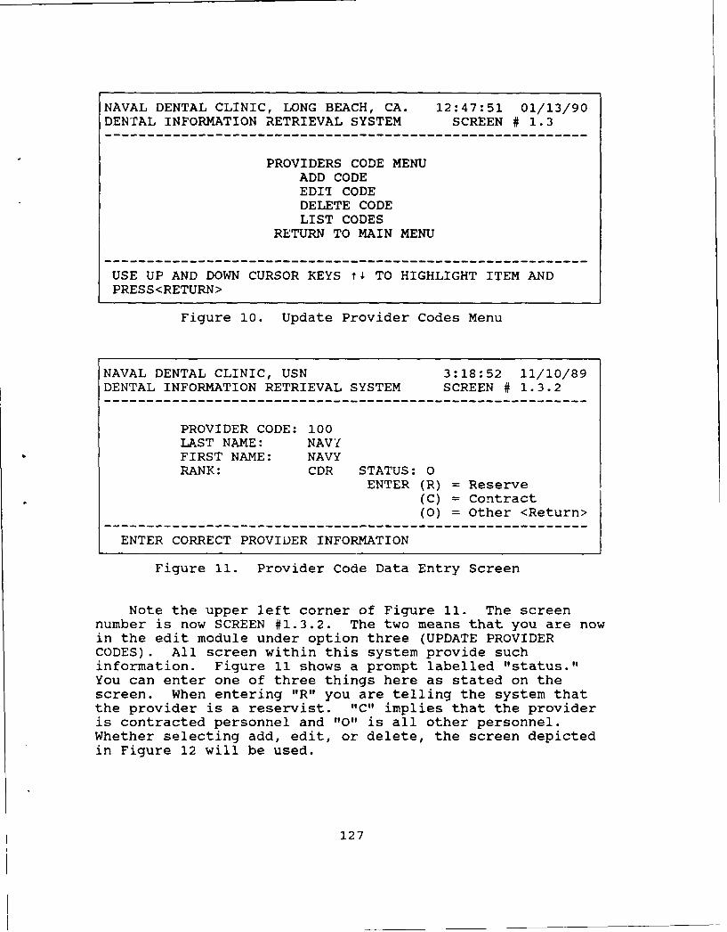
NAVAL DENTAL CLINIC, LONG BEACH, CA. 12:47:51 01/13/90DENTAL INFORMATION RETRIEVAL SYSTEM SCREEN # 1.3
PROVIDERS CODE MENUADD CODEEDIT CODEDELETE CODELIST CODES
RETURN TO MAIN MENU
USE UP AND DOWN CURSOR KEYS t TO HIGHLIGHT ITEM ANDPRESS<RETURN>
Figure 10. Update Provider Codes Menu
NAVAL DENTAL CLINIC, USN 3:18:52 11/10/89DENTAL INFORMATION RETRIEVAL SYSTEM SCREEN # 1.3.2
PROVIDER CODE: 100LAST NAME: NAVIFIRST NAME: NAVYRANK: CDR STATUS: 0
ENTER (R) = Reserve(C) = Contract(0) = Other <Return>
ENTER CORRECT PROVIDER INFORMATION
Figure 11. Provider Code Data Entry Screen
Note the upper left corner of Figure 11. The screennumber is now SCREEN #1.3.2. The two means that you are nowin the edit module under option three (UPDATE PROVIDERCODES). All screen within this system provide suchinformation. Figure 11 shows a prompt labelled "status."You can enter one of three things here as stated on thescreen. When entering "R" you are telling the system thatthe provider is a reservist. "C" implies that the provideris contracted personnel and "0" is all other personnel.Whether selecting add, edit, or delete, the screen depictedin Figure 12 will be used.
127

5. Report MenuThe Report menu (Figure 12) presents the user with a
number of options related to reporting of DIRS data byvarious chronological periods. Using the options availablein this menu, the current total of treatments, treatments byprovider, by command, etc. may be obtained. For example,the DAILY REPORT will repeat all information keyed-in viathe "INPUT DIRS DATA" selection. Also note that you will beasked whether or not you would like a daily report everytime you exit the system. Naturally, if no data has beenentered for that day no report will be generated.
Additionally, a Major Treatment Report option isavailable as a menu selection for internal reportingpurposes. Please note that the major report will query onup to ten user defined treatment code. Please note: youmust either change the printer font size (pitch) to 17pitch, or use wide printer paper for the report to fit withseven or more treatments. The system will forewarn you inthe event that wider paper is required.
NAVAL DENTAL CLINIC, LONG BEACH, CA. 12:49:38 01/13/90DENTAL INFORMATION RETRIEVAL SYSTEM SCREEN # 1.4
REPORT MENU
DAILY REPORTMONTHLY REPORTANNUAL REPORTPROVIDERS STATS.MAJOR TREATMENT REPORT
RETURN TO MAIN MENU
USE UP AND DOWN CURSOR KEYS t4 TO HIGHLIGHT ITEM ANDPRESS<RETURN>
Figure 12. Branch Clinic Report Menu
6. File Utilities MenuThe menu screen presented in Figure 13 offers the
system user the ability to reindex, backup, transfer, andstart a new recording year all from within the DIRSapplication. Providing these necessary functions fromwithin the system as menu-driven options helps simplify thenormally onerous and often neglected tasks such as backingup the system data.
128

NAVAL DENTAL CLINIC, LONG BEACH, CA. 13:50:16 01/13/90DENTAL INFORMATION RETRIEVAL SYSTEM SCREEN # 1.5
FILE UTILITIES
REINDEX DATA FILESBACKUP DATA FILESSTART NEW YEARTRANSFER DATA TO DISKRETURN TO MAIN MENU
USE UP AND DOWN CURSOR KEYS t TO HIGHLIGHT ITEM ANDPRESS<RETURN>
Figure 13. File Utilities Menu
The reindex data files option should be selected whenthe system shows signs of incorrect operation such asincorrectly assigned totals or data. As an example, reportsmay display zero work for all providers at a specifiedcommand for a given month. If this information isincorrect, using the reindex option will reassign theappropriate key field to their respective records. Thereindex feature is often required in any database system.Power surges, improper file closing and hardwaremalfunctions are examples of possible causal factors for4ndex distortion. The reindex option is provided toreestablish the proper links and pointers to correct thepotential damage caused by these malfunctions.
Selecting the backup data files option will store alldata on floppy disks. Be aware that your diskette must beformatted before any data can be captured on disk. See yourDOS manual on formatting floppies. It is stronQlvrecormended that backups be made at least once per week.Remember PCs are mechanical in nature. Should your PCbreakdown, having a current backup will save you many hours,if not days, of data reentry.
The "Start New Year" option is provided when the userswish to begin recordkeeping functions for a new reportingyear; either calendar, fiscal or other arbitrary selection.Failure to select this option when starting a new reportingperiod will result in overwritten data values and incorrecttotals for the selected period.
The "Transfer Data to Disk" optior is selected totransfer data for a monthly reporting period to a "floppydisk" for subsequent export to the appropriate Headquarterscommand. Production of the OCR report form may only be
129
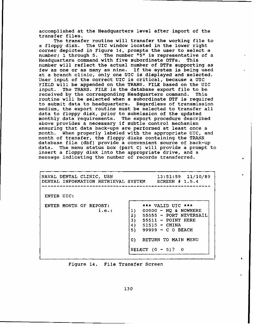
accomplished at the Headquarters level after import of thetransfer files.
The transfer routine will transfer the working file toa floppy disk. The UIC window located in the lower rightcorner depicted in Figure 14, prompts the user to select anumber; 1 through 5. The number "5" is representative of aHeadquarters command with five subordinate DTFs. Thisnumber will reflect the actual number of DTFs supporting asfew as one or as many as nine. If the system is being usedat a branch clinic, only one UIC is displayed and selected.User input of the correct UIC is critical, because a UICFIELD will be appended on the TRANS. FILE based on the UICinput. The TRANS. FILE is the database export file to bereceived by the corresponding Headquarters command. Thisroutine will be selected when a subordinate DTF is requiredto submit data to headquarters. Regardless of transmissionmedium, the export routine must be selected to transfer alldata to floppy disk, prior to submission of the updatedmonthly data requirements. The export procedure describedabove provides a necessary if subtle control mechanismensuring that data back-ups are performed at least once amonth. When properly labeled with the appropriate UIC, andmonth of transfer, the floppy disks containing the TRANSdatabase file (dbf) provide a convenient source of back-updata. The menu status box (part C) will provide a prompt toinsert a floppy disk into the appropriate drive, and amessage indicating the number of records transferred.
NAVAL DENTAL CLINIC, USN 13:51:59 11/10/89DENTAL INFORMATION RETRIEVAL SYSTEM SCREEN # 1.5.4
ENTER UIC:
ENTER MONTH OF REPORT: *** VALID UIC ***i.e.: 1) 00000 - HQ & NOWHERE
2) 55555 - PORT NEVERSAIL3) 55511 - POINT HERE4) 51515 - CHINA5) 99999 - C 0 BEACH
0) RETURN TO MAIN MENU
SELECT (0 - 5)? 0
Figure 14. File Transfer Screen
130

7. Headquarters MenuThe Headquarters menu (Figure 15) is intended for the
Headquarters command to facilitate the transfer of DIRS datafrom subordinate dental commands, and the obligatorysubmission of DIRS reports. To that end, file import/exportfacilities are provided as menu options tor operation fromwithin the DIRS application.
NAVAL DENTAL CLINIC, LONG BEACH, CA. 13:53:44 01/13/90DENTAL INFORMATION RETRIEVAL SYSTEM SCREEN # 1.6
HEADQUARTER'S MENU
IMPORT FILESEXPORT FILESDO REPORTS
START NEW YEAR (HQ ONLY)RETURN TO MAIN MENU
USE UP AND DOWN CURSOR KEYS t4 TO HIGHLIGHT ITEM ANDPRESS<RETURN>
Figure 15. Headquarter's Menu
7.1. IMPORT FILES.The "IMPORT FILES" option is provided to receive files
transmitted from subordinate commands.
7.2. EXPORT FILES.Similarly, the "EXPORT FILES" option is provided to
allow a Headquarters command to send a pre-selected month ofdata for all of its subordinate commands.
7.3. DO REPORTS.Selection of the "DO REPORTS" option will result in
the display of the screen presented in Figure 16 withprovisions for selection of either the DIRS OCR formatmonthly report or a "PROVIDERS STATS." internal reportoption.
131

NAVAL DENTAL CLINIC, LONG BEACH, CA. 13:53:44 01/13/90DENTAL INFORMATION RETRIEVAL SYSTEM SCREEN # 1.6.2
HEADQUARTER'S REPORTS
MONTHLY DIRS REPORTPROVIDER STATS.RETURN TO MAIN MENU
USE UP AND DOWN CURSOR KEYS t4 TO HIGHLIGHT ITEM ANDPRESS<RETURN>
Figure 16. Headquarters Reports
A. MONTHLY DIRS REPORTThe "MONTHLY DIRS REPORT" selection option is supported
by the menu screen presented in Figure 17. This selectionwill enable the Headquarters to print the standard monthlyNAVMED 6600/8 OCR form required for submission of DIRS datato COMNAVMEDCOM using an OCR font capable printer.
NAVAL DENTAL CLINIC, LONG BEACH, CA. 11:50:26 11/10/89DENTAL INFORMATION RETRIEVAL SYSTEM SCREEN W 1.5.1
SELECT UIC: 00000
Name of Facility: SEE TABLE 1
Provider's Hours: 12.00 *** VALID UIC ***
1) 00000 - HQ & LB CLINIC-- 2) 55555 - PORT NEVERSAIL
(1) Original I 3) 55544 - POINT HERE(2) Correction Select 4) 51515 - CHINA(3) resubmission I (1-3)? 5) 99999 - C 0 BEACH
0) RETURN TO MAIN MENU
SELECT (0 - 5)? 1
IS DATA CORRECT (Y/N)?
Figure 17. HQ OCR DIRS SCREEN
132

The first step in running this procedure is selecting aUIC which represents the reporting branch clinic. Stepnumber 2 is to enter the facility's name. Step 3 is theprovider's hour field from your monthly MEPRS report. Step4 is a selection representing the status of the report. Anoriginal report is the first submission for the reportingperiod. A correction is a submission to add, delete orcorrect data detected locally or by the OCR reader. Sincecorrected reports are not supposed to duplicate data, thecorrected reports will have to be typed manually. Correctedreports consist of applicable changes only; (i.e., additionsor deletions for specific treatment codes). A resubmissionis the forwarding of one, several, or all pages to MEDCOM-633 that were not read by OCR reader. A resubmission doesnot have to performed manually. The last step is avalidation field asking you to enter a "Y" (yes) or "N" (no)if the data is correct. Should you enter a no, you will beasked to select a UIC, or if you so desire at this time exitthis routine. When lining up the DIRS form in the OCRprinter, a lot of trial and error may be necessary at firstto line up the form exactly. Once lined up, it is highlyrecommended that you mark your printer so that next time youwill know exactly where to line up the form. The idealline-up is identified when an "L" is typed right on top ofthe OCR FORM "L."
B. PROVIDER STATS.The Provider Stats option at the Headquarters level is
a compilation of all subordinate DTF's Provider Statsreports. This routine is identical to the routine describedfor individual providers' stats. The only exception is thatthis report reflects the entire command. An example of theProvider Stats Report is provided in Appendix K.
C. START NEW YEAR (HQ ONLY).The "START NEW YEAR (HQ ONLY)" option provided on the
Headquarters menu is identical in function to that providedby the "START NEW YEAR" option for subordinate DTFs exceptthat it only reinitializes the headquarter's database. Aspreviously discussed, this option is used to initializerecords to zero, providing recordkeeping functions for a newreporting year; either calendar, fiscal or other arbitraryselection.
8. QUIT.As you probably have figured out the "Q" (QUIT) option
exits your system and returns you to the DOS prompt.
133

LIST OF REFERENCES
1. Department of the Navy, Navy Medical Command, Washington,D.C., NAVMEDCOMINST 6600.1B, MEDCOM-63, 17 September 1987.
2. Phone and personal conversations between Director of DentalServices, San Diego, Ca. (based on information receivedfrom CDR Diehl, BUMED, CODE MED 65, Washington, D.C.) andthe authors, December 1989 and January 1990.
3. Kroenke, D.M. and Dolan, K.A., Database Processing (ThirdEdition), Science Research Associates, Inc., Chicago,Illinois, 1988.
4. Grauer, R.T. and Sugrue, P.K., Microcomputer Applications(Second Edition), McGraw-Hill, Inc., New York, New York,1989.
5. Grauer, R.T. and Sugrue, P.K., Laboratory Manual toAccompany Microcomputer Applications (Second Edition),McGraw-Hill, Inc., New York, New York, 1989.
6. Simpson, A., dBASE III PLUS Programmer's Reference Guide,Sybex, Inc., Alameda, California, 1987.
134
. . . . . ...... . . . . . . . . . . . . . . . . . . . . . . . . . . . . . . . . . . . . . . . . . . .

INITIAL DISTRIBUTION LIST
No. Copies
1. Defense Technical Information Center 2Cameron StationAlexandria, Virginia 22304-6145
2. Library, Code 0142 2Naval Postgraduate SchoolMonterey, California 93943-5002
3. Library, Center for Naval Analyses 14401 Ford AvenueAlexandria, Virginia 22302-0268
4. Department of Administrative SciencesLibrary, Code 54 1
Naval Postgraduate SchoolMonterey, California 93943-5000
5. LCDR Robert Knight, Code AS/Kt 1Department of Adminisf-rative SciencesNaval Postgraduate SchoolMonterey, California 93943-5000
6. Prof. Magdi N. Kamel, Code AS/Ka 1Department of Administrative SciencesNaval Postgraduate SchoolMonterey, California 93943-5000
7. LT Roger Y. Kirouac, USNR 1942 Julie CourtFairfield, California 94533
8. CAPT Brad R. Triebwasser, USMC 1Rt #3 Box 147-EMilton-Freewater, Oregon 97862
9. Director of Dental Services 1NAVDENCLNBox 147NAVSTA, San Diego, California 92136-5247
10. Commanding Officer 1NAVDENCLNLong Beach, California 90822-5096
135

11. Commandant of the Marine CorpsCode TE-06Headquarters, U.S. Marine CorpsWashington, D.C. 20380-001
12. Commanding OfficerNaval Health Science Education and
Training CommandCode 2HSCBethesda, Maryland 20814-5022
13. NAVMEDDATSERCNT 1CDR Mark Dehl, Code 238901 Wisconsin AvenueBethesda, Maryland 20814-5066
136