naval postgraduate · pdf fileprice code 17. security ... naval postgraduate school december...
TRANSCRIPT
NAVAL
POSTGRADUATE SCHOOL
MONTEREY, CALIFORNIA
THESIS
Approved for public release; distribution is unlimited.
THE VIABILITY OF A METAMATERIAL SOLUTION FOR THE DEFENSE OF AN INCIDENT HIGH-ENERGY
ELECTROMAGNETIC BEAM by
Alex B. Baynes
December 2010
Thesis Advisor: James H. Luscombe Thesis Co-Advisor: Clyde L. Scandrett

THIS PAGE INTENTIONALLY LEFT BLANK

i
REPORT DOCUMENTATION PAGE Form Approved OMB No. 0704-0188Public reporting burden for this collection of information is estimated to average 1 hour per response, including the time for reviewing instruction, searching existing data sources, gathering and maintaining the data needed, and completing and reviewing the collection of information. Send comments regarding this burden estimate or any other aspect of this collection of information, including suggestions for reducing this burden, to Washington headquarters Services, Directorate for Information Operations and Reports, 1215 Jefferson Davis Highway, Suite 1204, Arlington, VA 22202-4302, and to the Office of Management and Budget, Paperwork Reduction Project (0704-0188) Washington DC 20503. 1. AGENCY USE ONLY (Leave blank)
2. REPORT DATE December 2010
3. REPORT TYPE AND DATES COVERED Master’s Thesis
4. TITLE AND SUBTITLE The Viability of a Metamaterial Solution for the Defense of an Incident High-Energy Electromagnetic Beam 6. AUTHOR(S) Alex B. Baynes
5. FUNDING NUMBERS
7. PERFORMING ORGANIZATION NAME(S) AND ADDRESS(ES) Naval Postgraduate School Monterey, CA 93943-5000
8. PERFORMING ORGANIZATION REPORT NUMBER
9. SPONSORING /MONITORING AGENCY NAME(S) AND ADDRESS(ES)
N/A
10. SPONSORING/MONITORING AGENCY REPORT NUMBER
11. SUPPLEMENTARY NOTES The views expressed in this thesis are those of the author and do not reflect the official policy or position of the Department of Defense or the U.S. Government. 12a. DISTRIBUTION / AVAILABILITY STATEMENT Approved for public release; distribution is unlimited.
12b. DISTRIBUTION CODE
13. ABSTRACT (maximum 200 words) Metamaterials have given rise to envisioning the design and engineering of materials through which light would be directed by design. The purpose of this thesis is to explore the idea of using transformational optics through the use of metamaterials as a way of defending against an incident electromagnetic beam. The theoretical and realistic viability of two possible proposed material solutions will be tested, through the use of the COMSOL Multiphysics software package.
15. NUMBER OF PAGES
97
14. SUBJECT TERMS Counter-Directed Energy Weapons, Directed Energy Weapons, Metamaterials, Transformational Optics, Cloaking, Free Electron Laser, Anti-Ship Missile, Office of Naval Research
16. PRICE CODE
17. SECURITY CLASSIFICATION OF REPORT
Unclassified
18. SECURITY CLASSIFICATION OF THIS PAGE
Unclassified
19. SECURITY CLASSIFICATION OF ABSTRACT
Unclassified
20. LIMITATION OF ABSTRACT
UU NSN 7540-01-280-5500 Standard Form 298 (Rev. 2-89) Prescribed by ANSI Std. 239-18

ii
THIS PAGE INTENTIONALLY LEFT BLANK

iii
Approved for public release; distribution is unlimited.
THE VIABILITY OF A METAMATERIAL SOLUTION FOR THE DEFENSE OF AN INCIDENT HIGH-ENERGY ELECTROMAGNETIC BEAM
Alex B. Baynes Lieutenant, United States Navy B.S., Cornell University, 2004
Submitted in partial fulfillment of the requirements for the degrees of
MASTER OF SCIENCE IN PHYSICS and
MASTER OF SCIENCE IN APPLIED MATHEMATICS
from the
NAVAL POSTGRADUATE SCHOOL DECEMBER 2010
Author: Alex B. Baynes
Approved by: James H. Luscombe Thesis Advisor
Clyde L. Scandrett Co-Advisor
Andres Larraza Chairman, Department of Physics Carlos F. Borges Chairman, Department of Applied Mathematics

iv
THIS PAGE INTENTIONALLY LEFT BLANK
v
ABSTRACT
Metamaterials have given rise to envisioning the design and
engineering of materials through which light would be
directed by design. The purpose of this thesis is to explore
the idea of using transformational optics through the use of
metamaterials as a way of defending against an incident
electromagnetic beam. The theoretical and realistic
viability of two possible proposed material solutions will
be tested, through the use of the COMSOL Multiphysics
software package.

vi
THIS PAGE INTENTIONALLY LEFT BLANK

vii
TABLE OF CONTENTS
I. INTRODUCTION ............................................1 A. DIRECTED ENERGY WEAPONS (DEW) ......................1 B. FREE ELECTRON LASER (FEL) ..........................1
1. Background ....................................2 2. Navy FEL Relevance ............................3
C. COUNTER-DIRECTED ENERGY WEAPONS (C-DEW) ............7 1. Navy Relevance ................................7 2. Problem Description ...........................7
II. METAMATERIALS ..........................................11 A. BACKGROUND ........................................11 B. PROPERTIES ........................................13 C. DESIGN AND MANUFACTURING ..........................16
III. TRANSFORMATIONAL OPTICS ................................17 A. BACKGROUND ........................................17 B. GENERAL FORMULATION ...............................19
IV. PROBLEM FORMULATION ....................................25 A. LASER .............................................25 B. TARGET MISSILE ....................................31 C. SIMULATION ENVIRONMENT ............................34
V. CYLINDRICAL CLOAKING MATERIAL SOLUTION .................35 A. SOLUTION SETUP ....................................35 B. COMSOL SIMULATIONS ................................43
VI. CYLINDRICAL DEFLECTION MATERIAL SOLUTION ...............51 A. SOLUTION SETUP ....................................51 B. COMSOL SIMULATIONS ................................51
VII. CONCLUSIONS ............................................61 A. FINDINGS ..........................................61 B. MATERIAL SOLUTIONS LIMITATIONS ....................62
APPENDIX. MODELING AND SIMULATION TUTORIAL FOR COMSOL 4.0 ...67
LIST OF REFERENCES ..........................................77
INITIAL DISTRIBUTION LIST ...................................79

viii
THIS PAGE INTENTIONALLY LEFT BLANK

ix
LIST OF FIGURES
Figure 1. FEL basic layout from [1]........................3 Figure 2. Depiction of the possible future of the FEL in
U.S. Naval onboard ship defense from [4].........5 Figure 3. Graphical portrayal of a material outer layer
redirecting electromagnetic energy away from sensitive components from [6]....................9
Figure 4. In conventional materials ε,μ derive from the constituent atoms; in metamaterials εeff,μeff derive from sub-units which are macroscopic systems whose size are of the order of the wavelength of light of interest from [7]........11
Figure 5. The difference in the optical density of air and ‘normal’ water (left) causes a straw in a glass of water to seem to be shifted at the interface and slightly enlarged inside the liquid. In ‘negative-index water’ (right), the straw would seem to continue in ‘the wrong direction’ from [8].............................14
Figure 6. Various polygonal and elliptical invisibility cloaks from [9].................................18
Figure 7. Simple cubic lattice of points in co-coordinate system (left) maps into a distorted mesh in the other co-coordinate system (right) from [11]....20
Figure 8. Left: in the , ,x y z coordinate system, space is single valued and a ray progresses through the region of negative refraction. Right: an equally legitimate view point is that the refractive index is everywhere positive, but space is triple valued, doubling back on itself so that each point within range of the lens is crossed three times from [7]....................22
Figure 9. Laser impact and the vaporization jet formed from [13].......................................27
Figure 10. Snapshot of the electric field distribution around the beam waist of a Gaussian beam. In this example, the beam radius is only slightly larger than the wavelength, and the beam divergence is strong. The field pattern is moving from left to right (i.e., toward larger x ) from [15]. ..................................29
Figure 11. (A) Intensity and electric field amplitude of a Gaussian laser beam from [16]. (B) Image shows

x
the Gaussian laser light intensity of a TEM00 dominant mode from [16].........................30
Figure 12. A Boeing Harpoon AShM from [18].................32 Figure 13. The thick blue line shows the path of the same
ray in (A) the original Cartesian space, and under two different interpretations of the electromagnetic equations, (B) the topological interpretation and (C) the materials interpretation. The position vector x
is shown
in both the original and transformed spaces, and the length of the vector where the transformed components are interpreted as Cartesian components as shown in (C) from [10]..36
Figure 14. Rays traversing a cylindrical cloak at an oblique angle. The transformation media that comprises the cloak lies in an annular region between the cylinders from [10].................41
Figure 15. Shows the incident electric Gaussian beam which is used in the simulations......................44
Figure 16. Z-component of the resulting electric field for the 2D cloaked cylindrical shell................45
Figure 17. Electric field magnitude for the 2D cloaked cylindrical shell...............................45
Figure 18. Shifted 0.05 cm. Z-component of the electric field for the 2D cloaked cylindrical shell......47
Figure 19. Shifted 0.05 cm. Electric field magnitude for the 2D cloaked cylindrical shell................47
Figure 20. Shifted 0.1 cm. Z-component of the electric field for the 2D cloaked cylindrical shell......48
Figure 21. Shifted 0.1 cm. Electric field magnitude for the 2D cloaked cylindrical shell................48
Figure 22. Shifted 0.15 cm. Z-component of the electric field for the 2D cloaked cylindrical shell......49
Figure 23. Shifted 0.15 cm. Electric field magnitude for the 2D cloaked cylindrical shell................49
Figure 24. Shows the incident electric plane wave that is used in the simulations.........................52
Figure 25. 3 . Z-component of the resulting electric field for the 2D cylindrical shell..............53
Figure 26. 2 . Z-component of the resulting electric field for the 2D cylindrical shell..............54
Figure 27. 1 . Z-component of the resulting electric field for the 2D cylindrical shell..............54
Figure 28. 0.5 . Z-component of the resulting electric field for the 2D cylindrical shell..............55

xi
Figure 29. 0.1 . Z-component of the resulting electric field for the 2D cylindrical shell..............55
Figure 30. 0.01 . Z-component of the resulting electric field for the 2D cylindrical shell.....56
Figure 31. Shows the incident Gaussian beam that is used in the deflection material solution simulations.....................................57
Figure 32. 0.01 . Resulting electric field magnitude for the 2D cylindrical shell....................58
Figure 33. 0.01 . Shifted 0.05 cm. Resulting electric field magnitude for the 2D cylindrical shell....59
Figure 34. 0.01 . Shifted 0.1 cm. Resulting electric field magnitude for the 2D cylindrical shell....59
Figure 35. 0.01 . Shifted 0.15 cm. Resulting electric field magnitude for the 2D cylindrical shell....60

xii
THIS PAGE INTENTIONALLY LEFT BLANK

xiii
LIST OF TABLES
Table 1. Boeing AGM-84 Harpoon AShM Specifications [17]..32 Table 2. AShM Modeling and Simulation Specifications.....33

xiv
THIS PAGE INTENTIONALLY LEFT BLANK

xv
LIST OF ACRONYMS AND ABBREVIATIONS
AShM Anti-Ship Missile
C-DEW Counter-Directed Energy Weapons
CG Guided Missile Cruiser
DEW Directed Energy Weapons
DDG Guided Missile Destroyer
FEL Free Electron Laser
FFG Guided Missile Frigate
LHA Amphibious Assault Ship
LHD Amphibious Helicopter Assault Carrier Dock
LPD Amphibious Transport Dock
LSD Landing Ship Dock
MLD Maritime Laser Demonstration
NRL Naval Research Laboratory
ONR Office of Naval Research

xvi
THIS PAGE INTENTIONALLY LEFT BLANK

1
I. INTRODUCTION
The subject matter pertaining to the problem statement
takes into account a wide variety of topics. A concise and
brief introduction to the background subjects of this thesis
are provided as a resource to the reader.
A. DIRECTED ENERGY WEAPONS (DEW)
A directed energy weapon is a weapon system that uses
targeted energy instead of a projectile. The weapon system
transfers energy from the source to the target, for the
desired effect. The energy can come in various forms, such
as electromagnetic radiation (typically lasers), accelerated
particles with mass (particle beam weapons), sound (sonic
weaponry), and fire (flamethrowers).
These weapons have often been seen in science fiction
and movies, but they are becoming a reality, and much
research is being done in this area in the form of basic and
applied physics. The Navy is specifically interested in the
areas of high-powered lasers or high-powered microwaves as
eventual weapons, and these areas of research have been
under investigation since the 1960s.
B. FREE ELECTRON LASER (FEL)
The DEW system that pertains most to the thesis problem
statement of defending against an electromagnetic beam
weapon is the FEL. The following provides an introduction to
the specifics of the system.

2
1. Background
A FEL system yields the same optical properties as a
conventional laser (most importantly, coherent
electromagnetic radiation which can reach high power),
however, beam formation takes place using very different
operating principles. Gas, liquid, and solid-state lasers
use electrons in bound atomic or molecular states to create
the beam after the electrons are excited. A FEL uses a
relativistic electron beam that is freely flowing, which has
very different physics behind beam formation.
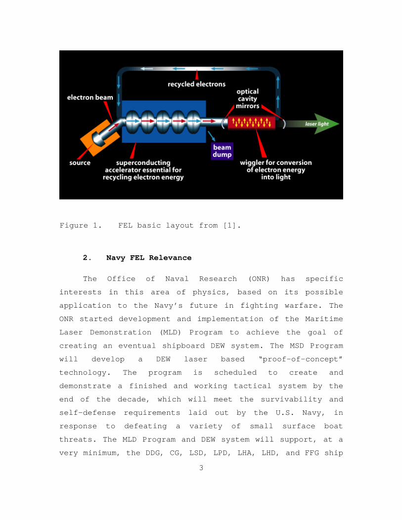
In a FEL, a beam of electrons is accelerated to very
high speeds (close to the speed of light). The electron beam
passes through a FEL undulator or “wiggler” section. The
undulator is composed of magnets with alternating poles
along the laser cavity. The undulator forces the electrons
to follow a sinusoidal path. A product of the electron’s
acceleration within the undulator is the release of photons
(light). Now, the significant attribute of the sinusoidal
motion of the electrons is that they are forced into phase
with the field, and so that the light being released will
also be in phase with the field. The important result is
that the emitted light, in phase with the field, will be
coherently added together. Through the use of mirrors, the
electromagnetic radiation can be stored within the laser
cavity. A basic layout of a typical FEL is displayed in
Figure 1.
3
Figure 1. FEL basic layout from [1].
2. Navy FEL Relevance
The Office of Naval Research (ONR) has specific
interests in this area of physics, based on its possible
application to the Navy’s future in fighting warfare. The
ONR started development and implementation of the Maritime
Laser Demonstration (MLD) Program to achieve the goal of
creating an eventual shipboard DEW system. The MSD Program
will develop a DEW laser based “proof-of-concept”
technology. The program is scheduled to create and
demonstrate a finished and working tactical system by the
end of the decade, which will meet the survivability and
self-defense requirements laid out by the U.S. Navy, in
response to defeating a variety of small surface boat
threats. The MLD Program and DEW system will support, at a
very minimum, the DDG, CG, LSD, LPD, LHA, LHD, and FFG ship

4
classes. The goal of the program is to develop and test a
system, which will lead to a subsequent U.S. Naval maritime
laser-based weapon System [2].
The U.S. Navy has interest in the development of a FEL
because it may be utilized to provide U.S. Naval platforms
with a highly effective and affordable point defense
capability. The Navy believes that this technology will be a
revolutionary gain, transforming ship defense. It is
envisioned to be used tactically to defeat various surface
and air threats, future anti-ship missiles (AShM), and
swarms of small boats. In addition, other possible missions
include “soft kills,” as well as extending the mission to
shore with relay mirrors to cut tank treads, melt gun
barrels, cut cables and communications, etc. The Navy also
sees other benefits to an onboard FEL system, which includes
use of this technology to provide counter-surveillance at
sea, advanced maritime situational awareness, and high-
resolution imagery with a beam director. The development of
a FEL onboard weapon system has been deemed a “game changer”
for the U.S. Naval warfare mission [3]. A pictorial
realization of this technology is depicted in Figure 2.
5
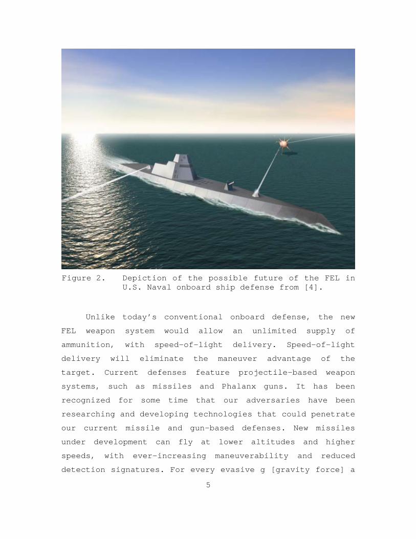
Figure 2. Depiction of the possible future of the FEL in
U.S. Naval onboard ship defense from [4].
Unlike today’s conventional onboard defense, the new
FEL weapon system would allow an unlimited supply of
ammunition, with speed-of-light delivery. Speed-of-light
delivery will eliminate the maneuver advantage of the
target. Current defenses feature projectile-based weapon
systems, such as missiles and Phalanx guns. It has been
recognized for some time that our adversaries have been
researching and developing technologies that could penetrate
our current missile and gun-based defenses. New missiles
under development can fly at lower altitudes and higher
speeds, with ever-increasing maneuverability and reduced
detection signatures. For every evasive g [gravity force] a

6
combatant threat can maneuver, a defensive weapon system
must incorporate three additional g’s for required kill
probabilities [4]. It is viewed that current defense
technology could be reaching physical limits, as well as
financial constraints, in keeping up with new attack
technologies [4].
A FEL weapon system would advantageously allow high
depth-of-fire, with only seconds of dwell time. It would be
used for a wide range of missions and threats, by being
designed to have both selectable wavelengths, as well as the
ability to control the strength of the beam for graduated
lethality or specific missions. It would allow precise
engagement with little collateral damage, compared to
explosive munitions. The FEL will, in theory, be powerful,
efficient, and reliable. Current FEL systems can run 24
hours a day, for weeks at a time. The FEL system, also, in a
purely economical sense, will save money. It would be an
alternative to the use of expensive ordinance against the
mission compatible targets. An engagement lasting just a few
seconds, would burn only a few gallons of fuel, costing the
Navy very little for an effective weapon, compared to
current conventional expensive weapons. Operational cost is
important for any weapon system. The lifetime cost of a FEL
weapon system could be a huge savings to a Navy budget [3].
Thus, the FEL seems to be the future for the U.S. Navy
defense. However, currently, it is still in the basic stages
of development. At this time, an Innovative Naval Prototype
(INP) program is underway, with the goal of creating a
scalable prototype of an eventual megawatt-class device. The
program’s focus will be on the design, development,

7
fabrication, integration, and testing of a 100-kW class FEL
weapon system [3]. Current research is stepping away from
the entire FEL system background. The focus is directed
towards pushing the individual subcomponents and subsystems
to their limits to get the power requirements to the needed
specifications [4].
C. COUNTER-DIRECTED ENERGY WEAPONS (C-DEW)
1. Navy Relevance
As part of an initiative for future survivability and
self-defense of the U.S. fleet, ONR, in conjunction with the
Naval Postgraduate School, U.S. Naval Academy, and the Naval
Research Laboratory have begun investigating basic research
into the area of countering DEW system threats [5].
The introduction chapter thus far has attempted to make
a case for DEW systems as the future of warfare for the U.S.
Navy. However, these advances in DEW systems will not be
one-sided and, as a result, C-DEW interest is becoming a
topic of great interest. The ONR C-DEW program is
investigating and developing basic research that will focus
on providing operational effectiveness in defending against
various known and projected airborne, surface, ground, and
underwater DEW systems threats. Basic research studies will
be conducted on new technologies, techniques, tactics, and
procedures for combating DEW threats [5].
2. Problem Description
C-DEW is a large topic and very diverse in its
research. The focus of this thesis is to explore the physics
of redirecting, deflecting, and/or reflecting energy from an
8
electromagnetic weapon, such as a FEL, described earlier in
this introduction. The FEL is likely to be one of the
threats of the future, and one of the proposed defenses
against such a threat involves a material sided solution in
the form of a protective outer layer.
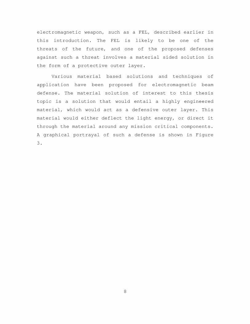
Various material based solutions and techniques of
application have been proposed for electromagnetic beam
defense. The material solution of interest to this thesis
topic is a solution that would entail a highly engineered
material, which would act as a defensive outer layer. This
material would either deflect the light energy, or direct it
through the material around any mission critical components.
A graphical portrayal of such a defense is shown in Figure
3.
9
Figure 3. Graphical portrayal of a material outer layer redirecting electromagnetic energy away from sensitive components from [6].
It has been proposed through the use of metamaterials
and transformational optics (both of which will be discussed
in detail in subsequent chapters) that perhaps a material
could be engineered and manufactured that would have the
intrinsic properties to redirect and/or deflect radiation,
as a primary form of defense against an electromagnetic
energy threat.
The goal of writing this paper is to research such
materials, learn and understand the physics of
transformational optics, apply the material and physics to
the problem of electromagnetic defense, explore computer

10
modeling and simulation of the problem, address the future
applicability of such a solution, and, finally, to determine
whether future research in this area may be justified.

11
II. METAMATERIALS
A. BACKGROUND
Metamaterials are a new class of materials that possess
intrinsic electromagnetic properties that do not normally
exist in nature. As a result, they are highly engineered and
often require a very complex manufacturing process. Their
abnormal intrinsic electromagnetic properties are due to
their sub-wavelength structure, which is obviously
significantly different than most materials whose intrinsic
properties rely on their inherent chemical composition [6].
A depiction of the underlying structural differences is
presented in Figure 4.
Figure 4. In conventional materials ε,μ derive from the constituent atoms; in metamaterials εeff,μeff derive from sub-units which are macroscopic systems whose size are of the order of the wavelength of light of interest from [7].

12
Conventional materials interact with light according to
the individual atoms and molecules from which they are made
[7]. Of main interest to physicists are the macroscopic
electromagnetic fields, which interact with the material.
These macroscopic fields are nothing more than averages over
the fluctuating local fields. However, these macroscopic
fields are very well determined because there are typically
billions of molecules per cubic wavelength of matter [7].
Metamaterials mimic the building block structure of nature,
by replacing the molecules by man-made structures. To
construct materials with the effective properties for a
specific wavelength, the underlying structures must have
characteristic lengths smaller than that of the wavelength
for which they have been designed. For example, the
metamaterial underlying structure might have dimensions of
nanometers for visible light, or up to a few millimeters for
microwave radiation [7].
The highly significant excitement relating to
metamaterials lies in the fact that their inherent
inhomogeneous design offers a completely novel approach to
controlling light. It is now thought that the future of
metamaterials will be a manufacturing process, in which a
structure will be designed on the sub-wavelength scale, in
which its permittivity and permeability values will be
designed to be independently determined within the structure
[6]. The resulting structure would have a varying index of
refraction tailored according to its specific
electromagnetic design requirements. Conceivably, one could
design and manufacture materials whose refractive index
could virtually guide light through any path within the
material. As a result, metamaterial applications are

13
abundantly being theorized and designed. The problem,
however, lies not in the application, but the availability
of methods to engineer and manufacture the appropriate
metamaterials. It is very apparent that the theory and
formulation behind controlling light within a material is
far beyond the current technology and ability to manufacture
these complex materials. However, the development of new and
more complex manufacturing techniques is increasing at an
astonishing rate. As a result, research into a metamaterial
solution to the problem of redirecting and deflecting of an
electromagnetic energy source should not be hindered by the
current technology available for manufacturing. Current
basic research must be done to determine if such solutions
are viable and can be computer-simulated, while
manufacturing technologies catch up with theoretical goals.
B. PROPERTIES
Metamaterial structures, as described earlier, are
engineered and have properties not associated with materials
normally found in nature. An almost unsettling depiction
into the unnaturalness of the properties of light
interaction within metamaterials is rendered in Figure 5,
which shows what a fictional metamaterial could do.

14
Figure 5. The difference in the optical density of air and ‘normal’ water (left) causes a straw in a glass of water to seem to be shifted at the interface and slightly enlarged inside the liquid. In ‘negative-index water’ (right), the straw would seem to continue in ‘the wrong direction’ from [8].
A metamaterial affects incident electromagnetic
radiation if its underlying structure is smaller than the
wavelength of the incident radiation. As a result, the
smaller the wavelength, the more complex the material’s
manufacturing process will be. This fact is an important and
differentiating plus for material solutions in
electromagnetic radiation defense. A FEL beam, to be of any
use, must travel through the atmosphere over a certain range
to its target. In the design and application process for a
FEL, smaller and smaller wavelengths of radiation are
instantly ruled out, due to interaction with the atmosphere

15
itself. It is predicted that a FEL laser being used as a
weapon will generally operate in the infrared to microwave
wavelength range. This implies, for C-DEW defense, a
metamaterial structure that may be easier, albeit not
currently possible to manufacture.
An important and fundamental aspect of engineering
metamaterials is loss. Currently, known metamaterials are
generally comprised of metallic materials that will
undesirably absorb a great deal of the incident radiation.
This poses a concern because if the material is damaged
while redirecting a high-powered laser beam (due to
overheating, melting, or disintegration) then the material
could become less effective. As a result, a metamaterial
solution layer would have to be highly efficient considering
the power magnitudes proposed by FEL weapon systems
currently being developed. While the problem of loss is a
current drawback, it is also an inevitable constraint on a
material sided solution. However, it does not justify
abandoning the basic nature of research in this thesis.
Considerable research is currently being undertaken to
design more efficient metamaterial structures. One advantage
in this line of research is that metamaterials have so many
desired applications. The application abundance is
translating into a lot of positive hype. As a result there
is a growing industry investing in the science of
engineering and manufacturing of new and more efficient
metamaterials.
16
C. DESIGN AND MANUFACTURING
At frequencies in the GHz range, conversion of energy
to heat loss in currently designed metamaterials is mainly
attributed to the dielectric component of the structure of
the material [7]. Loss in this range becomes less of an
issue when compared to metamaterials designed for higher
frequency regimes [7]. Also, frequencies in this range
translate to longer wavelength scales. This requires the
manufacture of less complex micro-structures that is within
reach of current technology [7]. Perhaps the most limiting
aspect of research into metamaterials is the need for cheap
and efficient manufacturing techniques capable of making
these 3D structures [7]. Most designs are assembled by
building up 2D panels on top of one another, in a very low
tech way. This process will have to be improved and
optimized before metamaterial promise and designs can be
utilized outside of the laboratory [7].

17
p
cn
n
III. TRANSFORMATIONAL OPTICS
A. BACKGROUND
In optical physics, every material can be defined by
its refractive index property. It is defined to be the ratio
between the speed of the electromagnetic radiation passing
through a vacuum ( c) and the speed of the wave propagating
through the material ( p ) for a given wavelength:
(3.1)
In terms of electromagnetic radiation, the index of
refraction is comprised of the material properties of
permittivity ( ), the polarizability response due to an
electric field, and the permeability ( ), the response due
to a magnetic field.
(3.2)
Most materials have refractive indices larger than one. One
can see from the above equation that a negative index of
refraction is impossible to achieve. However, over the last
decade, significant research has been done to use common
materials with indexes above one and arranging them in ways
that their structure rather than their individual indices
determine the composite’s electromagnetic properties.
Metamaterials are examples of this concept that allow, in
theory, composite structures with negative indices of
refractions.
18
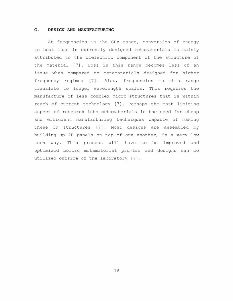
Variability of a material’s refractive index is the
basis for construction of metamaterials that have the
property of being able to guide electromagnetic radiation as
it propagates within the material. Transformational optics
is a fairly recent branch of mathematical physics that
theoretically postulates ideas that have traditionally been
exclusive to science fiction. Research is currently being
done in the areas of cloaking, invisibility, electromagnetic
wormholes, and perfect lenses (resolution beyond the limits
of wavelength). A few pictures of invisibility cloaks are
shown in Figure 6.
Figure 6. Various polygonal and elliptical invisibility cloaks from [9].
19
0
0
,t
t
HE
EH
The rise of transformational optics, and the interest
in metamaterials, invites the possibility of a material
solution as a counter to the threat of a high-energy
electromagnetic radiation weapon. Utilizing a material
layer, it is hypothesized that it could cloak or simply
divert the incident radiation around or away from high value
or sensitive components. Both possibilities will be explored
in this thesis. However, we first must give a general
formulation of transformational objects, so that we may have
a more complete understanding of the development of each.
B. GENERAL FORMULATION
The method of transformational optics for Maxwell’s
equations is outlined by J.B. Pendry, D. Schurig, and D.R.
Smith in [10]. The method uses Cartesian tensors to create a
blueprint for the required material properties of the
metamaterials. This paper uses the Minkowski form of
Maxwell’s equations for a general space-time transformation
from which results of [10] are reported below. A complete
derivation of the equations is unnecessary and beyond the
necessary scope of this thesis. Equations presented are used
to set up a possible material solution to the problem in
Chapter IV.
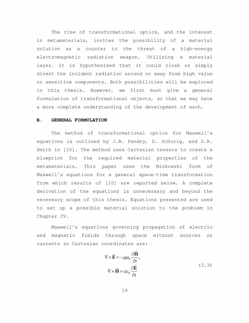
Maxwell’s equations governing propagation of electric
and magnetic fields through space without sources or
currents in Cartesian coordinates are:
(3.3)

20
1 1 2 3 2 1 2 3 3 1 2 3( , , ), ( , , ), ( , , )x x x x x x x x x x x x
In this form, the permittivity (ε) and the permeability (μ)
are generally tensors. The form of the equations gives the
freedom that both ε and µ may depend on the position within
space. Next, we wish to transform the Cartesian system to
that of a new coordinate system defined by,
(3.4)
Because these are completely generalized, coordinates
equally spaced points along the 1 2 3, ,x x x axes may appear
distorted in the original 1 2 3, ,x x x coordinate frame. See
Figure 7.
Figure 7. Simple cubic lattice of points in co-coordinate system (left) maps into a distorted mesh in the other co-coordinate system (right) from [11].
Thus far, Maxwell’s equations have been written in the
original Cartesian system. Expressed in terms of the new
coordinates - 1 2 3, ,x x x , the transformed set of equations in
the primed coordinate system becomes
21
0
0
,t
t
HE
EH
1 1( ) , ( )
1 1,
det det
T T
T T
E A E H A H
A A A AA A
1, i iij ij
j j
x xA A
x x
(3.5)
where and are again tensors, and E and H
are
renormalized electric and magnetic fields. The takeaway from
this transformation is that all four new quantities are
related to their originals. This is important because it
means that Maxwell’s equations are preserved through the
transformation.
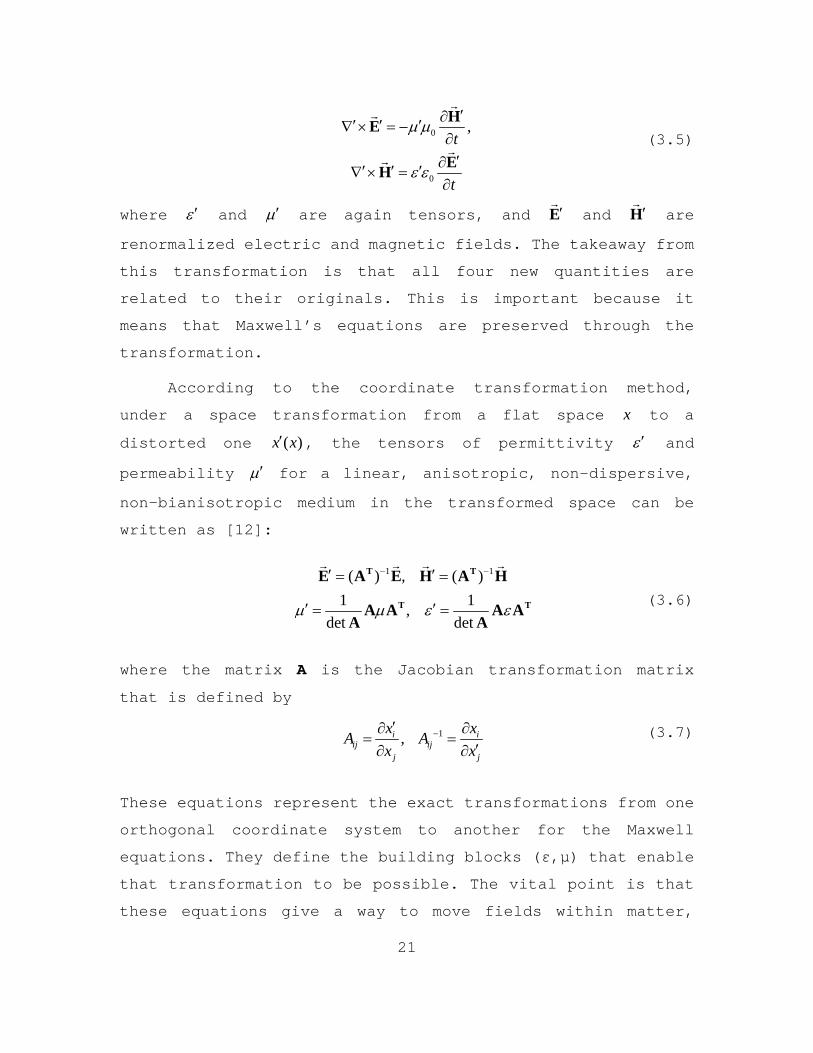
According to the coordinate transformation method,
under a space transformation from a flat space x to a
distorted one ( )x x , the tensors of permittivity and
permeability for a linear, anisotropic, non-dispersive,
non-bianisotropic medium in the transformed space can be
written as [12]:
(3.6)
where the matrix A is the Jacobian transformation matrix
that is defined by
(3.7)
These equations represent the exact transformations from one
orthogonal coordinate system to another for the Maxwell
equations. They define the building blocks (ε,μ) that enable
that transformation to be possible. The vital point is that
these equations give a way to move fields within matter,

22
based on design. The birth of metamaterials has given rise
to, and the ultimate promise of, being able to ultimately
control electromagnetic waves through matter. We will use
Equations (3.6) and (3.7) in Chapter V to form and develop a
possible material solution to the problem of directing
electromagnetic waves to protect from a DEW threat.
First, however, as an example outlined by [7], we apply
transformational optics and Equations (3.6) and (3.7) to
gain insight into another interpretation of the Veselago
lens, which is depicted in Figure 8.
Figure 8. Left: in the , ,x y z coordinate system, space is single valued and a ray progresses through the region of negative refraction. Right: an equally legitimate view point is that the refractive index is everywhere positive, but space is triple valued, doubling back on itself so that each point within range of the lens is crossed three times from [7].
The Veselago lens exists in real space ( , , )x y z , which is
depicted in the image on the left in Figure 8. However, when
observing the lens from the outside, one perceives the
region between the object plane and the image plane to
vanish. The following coordinate transformation expresses
this by mapping real space ( , , )x y z on to a triple valued
space ( ', ', ')x y z ,

23
1
1 1 1
1
' , ' ,
' , ,
' (2 - ), ,
' - 2 ,
y y z z
x x x x
x x x x x x d
x x d x d x
1
1 1
1
1, ,
1, ,
1,
x x
x x x d
x d x
(3.8)
where the lens lies in the interval 1 1x x x d .
Straightforwardly applying Equations (3.6) and (3.7) to the
transformation formulae listed in Equation (3.8) yields,
(3.9)
This shows that the triple valued distorted space defined by
Equation (3.8) can be created using the blueprint for the
material properties shown in Equation (3.9), which is
exactly how the Veselago lens is defined in Figure 8. This
example gives a geometrical interpretation to the lens. The
interpretation is that the Veselago lens is comprised of a
section of 'negative' space that annihilates an equivalent
thickness of vacuum [7].

24
THIS PAGE INTENTIONALLY LEFT BLANK

25
IV. PROBLEM FORMULATION
High-energy electromagnetic radiation weapons (e.g. a
FEL) are the future of U.S. Naval warfare, and are
anticipated to, not only be realized in the next decade, but
to be operational. It is foreseeable that our opponents will
also develop such weapons, and therefore, we must create
defenses against such threats. The primary mission being
explored is that of close-in carrier missile engagement
defense. It is foreseeable that U.S. adversaries will be
developing said weapon systems for the same mission.
There are countless uses for metamaterials and
transformation optics, some most likely have not even been
idealized, as of yet. But for the purpose of this thesis, we
will explore two material solutions to the defense of a
hostile electromagnetic radiation beam weapon upon a U.S.
inbound missile. In order to properly, even if loosely,
simulate the laser and the missile, we must first define the
parameters, assumptions, approximations, and environment to
which our computer simulations will be conducted. The next
few sections will define the model, which will be used to
best test and explore the possible material solutions that
will be analyzed in the follow-on chapters.
A. LASER
To model an enemy hostile laser, we will need to make
some generalities, approximations, and assumptions needed to
model both proposed theoretical material solutions. First of
all, we will model the entire system to be a steady state
simulation. A FEL generally operates tactically on a “dwell

26
time,” where it is predicted that a beam a few seconds on
target will destroy up to approximately 1 litre of material.
We will take the entire laser beam model to be in a steady
state environment, and are interested in how the
electromagnetic radiation interacts with the target and how
in the presence of the possible material solutions will
determine the resulting fields. This is not exactly the
case, because the beam will not exactly be incident on the
same spot for a few seconds duration. A way to think about
the simulation model is an instantaneous snapshot of the
incident and resulting electromagnetic fields in the
presence of the material solutions.
We will generalize the hostile laser in the simulations
as having a wavelength of 5 cm. Electromagnetic radiation
weapons are idealized to operate as a weapon in-between the
infrared and microwave wavelength regions, as a result of
atmospheric effects and optimum conditions, to perform
maximum damage. This puts the chosen simulation wavelength
in a suitable spot within the proposed wavelength region,
however, a smaller wavelength on the order of a micrometer
would be a far more realistic input. The simulations,
however, are limited by the meshing requirements of the real
dimensions used by the modeling program. It has been
determined in modeling this specific problem of a missile,
having a diameter dimension on the order of a meter, that
anything below the chosen wavelength is difficult to
simulate and solve. A more realistic study would include a
wavelength input of a Navy FEL weapon system currently being
developed. A more important aspect of the problem of a
proposed FEL wavelength range is that further study will
need to be conducted to determine how applicable and
27
forgiving a material solution would be in regard to
variation in frequency, since metamaterials are very
specifically designed, based on a specific incident light
wavelength. If the laser is assumed to be able to be tuned,
this could have a drastic importance of whether the
metamaterial solutions presented are even remotely viable.
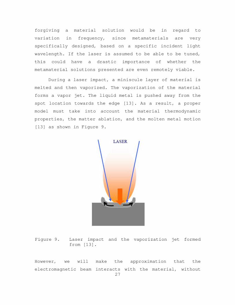
During a laser impact, a miniscule layer of material is
melted and then vaporized. The vaporization of the material
forms a vapor jet. The liquid metal is pushed away from the
spot location towards the edge [13]. As a result, a proper
model must take into account the material thermodynamic
properties, the matter ablation, and the molten metal motion
[13] as shown in Figure 9.
Figure 9. Laser impact and the vaporization jet formed from [13].
However, we will make the approximation that the
electromagnetic beam interacts with the material, without

28
2 21
0 2( , ) exp exp tan
( ) ( ) 2 ( )o
R
w r x ikrE r x E ikx i
w x w x x R x
the physical processes that have just been described. We are
more interested in the basic research of the fields that
arise from interaction with the material solutions than the
thermodynamic properties at the boundary layers and the
drilling that may or may not occur. Shining a FEL on
possible material solutions, presented in this thesis would
be an excellent topic for further research, depending on the
results determined.
We will model the hostile incident electromagnetic beam
as one, which approximates a Gaussian profile. In this case,
the beam is said to be operating on the fundamental
transverse mode. This is a good approximation because
Gaussian beams are often the simplest and most desirable
type of beam for a laser source [14]. A laser beam, in
reality, is a 3D problem, however we will approximate the
beam in all simulations as a 2D laser beam in which there
will be one transversal dimension x and one axial dimension
r . The expression for the complex electric field amplitude
distribution of a Gaussian laser beam propagating in the x
direction can be written as in [15],
(4.1)
Where r is the radial distance from the center axis of the
beam, x is the axial distance from the beam’s narrowest
point (the “waist”) and the direction of propagation, 0E is
the peak amplitude, 2
oR
wx
is the Rayleigh length, which
determines the length over which the beam can propagate

29
without significantly diverging, ( ) 1 /o Rw x w x x is the beam
radius, with ow being the radius at the beam waist, 2
k
is the wave number, is the wavelength, and
2( ) 1 /RR x x x x is the radius of curvature of the
wavefronts. A fully developed Gaussian laser beam is
depicted in Figure 10, and the spot profile is shown in
Figure 11.
Figure 10. Snapshot of the electric field distribution around the beam waist of a Gaussian beam. In this example, the beam radius is only slightly larger than the wavelength, and the beam divergence is strong. The field pattern is moving from left to right (i.e., toward larger x ) from [15].

30
Figure 11. (A) Intensity and electric field amplitude of a Gaussian laser beam from [16]. (B) Image shows the Gaussian laser light intensity of a TEM00 dominant mode from [16].
A subtle yet important aspect of using the 2D complex
electric field amplitude distribution of a Gaussian laser
beam in our simulations is that it is only an approximation
to that of the actual 3D equation. The approximated 2D beam
used in simulations does not rigorously satisfy Maxwell's
equations. As a result, there will be noticeable effects in
the later presented simulations. However, it is felt, that
using a 2D approximated laser beam is more beneficial to
modeling the problem as a whole then merely using a plane
wave in all simulations. All beam simulations will use the
approximated 2D Gaussian beam of Equation (4.1) with the
following beam properties:
= 5 cm
ow = 8 cm (25% of the target missile diameter)
0E = 1 (Normalizing the electric field magnitude)
31
The reasoning behind the chosen input wavelength has already
been discussed. The beam waist has been chosen to be 25% of
the missile diameter to appropriately model a diverging
laser beam that has traveled some distance. Any larger, and
the simulation of a plane wave would be justified. Any
smaller, and the resulting electric field is difficult to
discern visually based on the dimensions of the entire
problem. The electric field magnitude has been normalized
because the simulations are only concerned with the form of
the resulting electric field immediately around and within
the material layer.
B. TARGET MISSILE
Based on our setup, we need to define some dimensions
about the missile we are going to be modeling and using in
the material solution simulations. We will be modeling a
very general AShM, and since the purpose of this research
topic is a basic research concept (and not to design a
specific material solution for a specific U.S. Navy weapon
system), we will present numbers as just a general tool and
no way should they be construed to be actual future design
specifications.
The specifications used in this research were actually
found using the “Google” search engine, with the search
query being “anti-ship missile dimensions.” Given this line
of research into possible AShM specifications, a Wikipedia
article was discovered that listed all the specifications
needed for our modeling and simulation purposes. The Website
lists the specifications for the Boeing AGM-84 Harpoon AShM
varieties, one of which is reproduced in Table 1.
32
Table 1. Boeing AGM-84 Harpoon AShM Specifications [17].
Air Launched 3.8 m Length Surface/Submarine
Launched 4.6 m
Air Launched 519 kg Weight Surface/Submarine
Launched 628 kg
Diameter 0.34 m
Wing Span 0.914 m
Speed 240 m/s
Warhead 221 kg
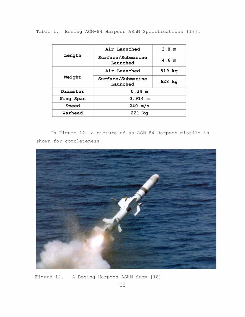
In Figure 12, a picture of an AGM-84 Harpoon missile is
shown for completeness.
Figure 12. A Boeing Harpoon AShM from [18].

33
We will make the approximation that the simulated
missile is represented by an infinitely long cylinder, and
thus simplifies the simulation problem from a 3D problem to
a 2D problem. This greatly reduces the complexity of the
geometry and inputs, but more importantly reduces the
necessary computational processing power to simulate the
problem. The 2D cylinder approximation becomes erroneous
close to the ends and over non-cylindrical geometries on the
rocket (such as fins). However, we will neglect these non-
idealized effects in the present analysis of our feasibility
study.
We must also make the approximation of a skin layer
specification for the proposed missile simulations. The
purpose of the missile is to deliver a weapon package to the
target, and the goal of the solution is to protect the
essential weapon package from an electromagnetic beam
threat. The material solution skin layer thickness cannot be
unrealistically large in our modeling because that would not
be a very effective addition to a current missile system,
and would most likely yield any current system ineffective.
For the purposes of this thesis, we will model the material
solution skin layer as 25% of the overall missile radius.
The following dimensions for the modeled target missile,
listed in Table 2, will suffice for the remainder of the
thesis:
Table 2. AShM Modeling and Simulation Specifications
Package Radius 12 cm
Skin Layer Thickness 4 cm
Missile Radius 16 cm

34
C. SIMULATION ENVIRONMENT
In analyzing the two possible material solutions
presented in this thesis, we have hypothesized parameters
for the incident electromagnetic radiation and the missile
material solution shell to be modeled. The difference
between the two solutions will be in how we design the
material properties of the two metamaterial skin layers. In
all but the skin layers, the models and simulations will be
exactly the same.
To analyze the proposed possible material solutions, we
will employ the COMSOL Multiphysics simulation software
environment. It allows the user to build, mesh, and solve
the entire numerical model in one software environment. We
will additionally, and necessarily, use the Radio Frequency
(RF) Module, which provides the user the added capability of
modeling the propagation of electromagnetic waves in and
around the missile structure. Furthermore, the RF Module
allows the user to define metamaterials with engineered
properties, no matter the anisotropic nature of the
material. The finite element-based electromagnetic solver in
the COMSOL Multiphysics package is of particular use to this
thesis because of the flexibility it allows, in specifying
material anisotropy and inhomogeneity within the modeled
missile.
To demonstrate the modeling environment, a tutorial for
setting up the models using the COMSOL Multiphysics package
is presented in the Appendix.

35
V. CYLINDRICAL CLOAKING MATERIAL SOLUTION
A. SOLUTION SETUP
The first possible material solution to our problem of
defending against a high-energy electromagnetic threat would
be to create a metamaterial shell around sensitive
components that could redirect an incident electromagnetic
beam around sensitive components. Our solution does not
require invisibility as a necessary constraint for defense.
Using transformational optics, we derive the geometry and
material constraints necessary to design an effective
metamaterial cloaking skin.
Using the methodology described by J.B. Pendry, D.
Schurig, and D.R. Smith in [10], we have the material
constraints required in designing the cylindrical cloak. In
essence it is a cylindrically symmetric coordinate
transformation that compresses all the space in a volume of
radius b centered about the cylinder into a cylindrical
shell of inner radius a and outer radius b . To visualize
the transformation, consider a position vector x with
Cartesian coordinates ix . In the transformed space, the
position vector will have coordinates ix as shown in Figure
13.
36
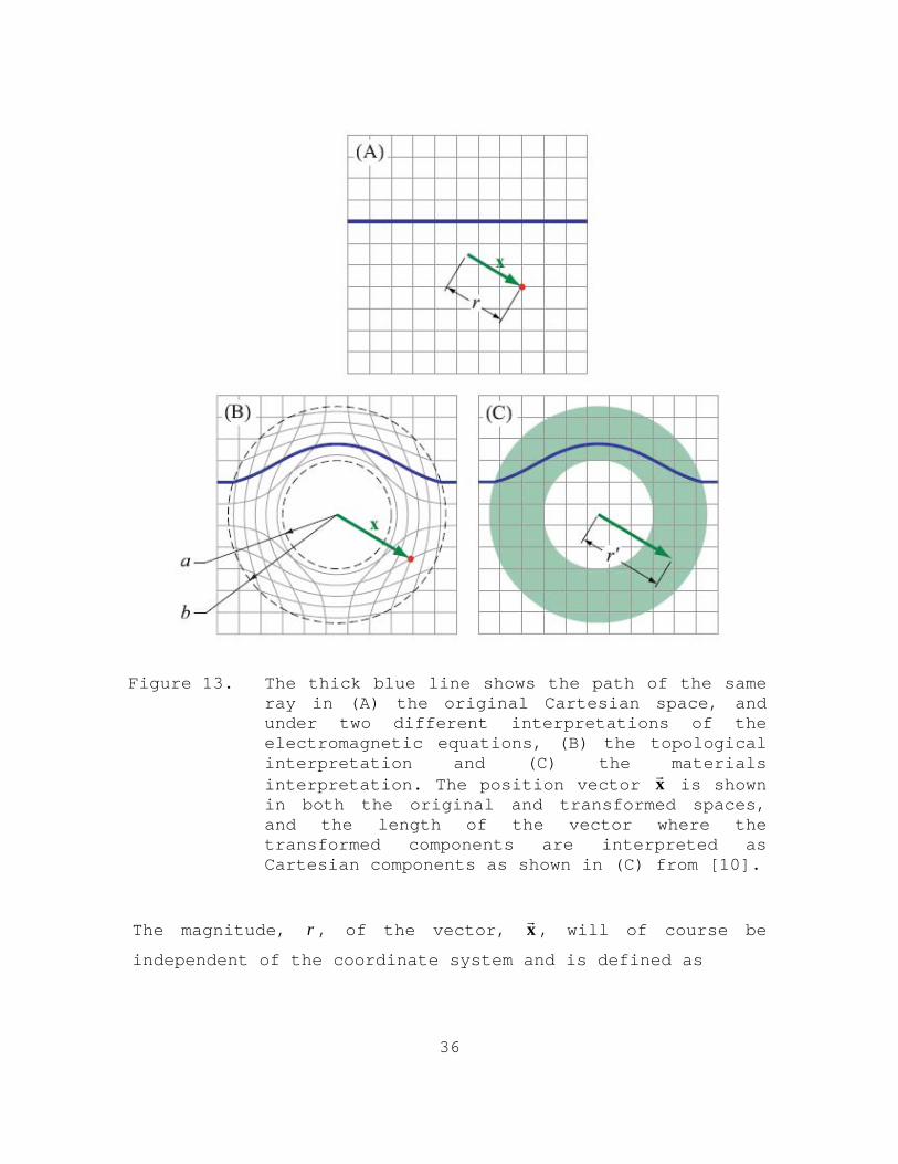
Figure 13. The thick blue line shows the path of the same ray in (A) the original Cartesian space, and under two different interpretations of the electromagnetic equations, (B) the topological interpretation and (C) the materials interpretation. The position vector x
is shown
in both the original and transformed spaces, and the length of the vector where the transformed components are interpreted as Cartesian components as shown in (C) from [10].
The magnitude, r , of the vector, x, will of course be
independent of the coordinate system and is defined as

37
b ar r a
b
1/ 2 1/ 2' '( ) ( )i j i j
i j i jr x x x x g
1/ 2' '( )i j
i jr x x
i iii
x x
r r
(5.1)
Where ' 'i ig is the metric of the transformed space. However,
in the materials interpretation we will take the components
ix to be the components of a Cartesian vector. Also, the
magnitude, which we will call r, is calculated in Cartesian
space by,
(5.2)
The spaces will represent a transformation from a
cylindrical space to a cylindrical transformation space. An
appropriate transformation for this purpose would be one in
which the transformation maps points from a radius r to a
radius r as follows,
(5.3)
We see that, importantly, when 0r , then r a , and that,
when r b , then r b . We will apply the transformation over
the domain, 0 r b (or equivalently, a r b ). Outside of
the domain, we assume the identity transformation, r r .
Next, we need to relate all the variables together.
Since our transformation is radially symmetric, the unit
vectors in both the material interpretation and original
space are equivalent.
(5.4)

38
ii i i i
i i
b a xx x a
b r
3 3
1 1 2 2
i jij
i j i jij
Z
T
3
ii i i i k ij j j kj i
j
x r aA x x
x r r
Using equations (5.3) and (5.4), we can express the
components of the position vector in the transformed space,
in terms of only the components in the original space, to
obtain,
(5.5)
Now that we have the relation, we can calculate the
transformation matrix ijA .
(5.6)
However, this is not totally correct for our problem. Thus
far, we have defined the transformation in a spherical
sense. The transformation is the same as that of the
spherical case, only that now it is applied only to the two
dimensions normal to the cylinder’s axis. To analyze a
cylindrical transformation, we need the help of two
projection vectors: one that projects on to the cylinder’s
axis, and one that projects onto the plane normal to the
cylinder’s axis.
(5.7)
We see that the transformation matrices for spherical and
cylindrical geometries will be very similar. The
transformation will be the same in the plane, normal to the
cylinder’s axis, and the transformation in the direction of

39
3i i i k i ij j kj i j
r aA T r r Z
r r
2
3 3
2
3 3
0
0
0 0 1
ij
r ax axy
r r r
axy r ayA
r r r
det( )ij
r a rA
r r
the axis of the cylinder will be the identity matrix. We can
now rewrite the spherical transformation matrix Equation
(5.6) with the help of (5.7) as follows,
(5.8)
The transformation matrix can be written out using its
components, where r is now the distance from the cylinder’s
axis,
(5.9)
As seen in the matrix above, we have now defined the plane,
normal to the cylinder’s axis as the x-y plane, and the
cylinder’s axis as the z plane for convenience.
We can easily calculate the determinant that will be
needed to determine the material properties by rotating the
matrix into a coordinate system where the off-diagonals
vanish. We then find the determinant to be,
(5.10)
Now, putting all the pieces together, we are able to
solve for the material properties needed to cloak the
cylinder. Using Equation (3.7), (5.9), and (5.10) and
considering that our original space has both a permittivity
40
22
3
2
( )
r ar a b r a
r a r r a b a r
T r r Z
r r
r a
r
r
r a
2
z z
b r a
b a r
and permeability equal to one, the formula for the material
properties in the transformed space in direct notation and
dropping the primes are,
(5.11)
Finally, if we rotate the system to where the off-diagonal
elements vanish, we get the individual components of the
material parameters for a cylinder in cylindrical
coordinates.
(5.12)
(5.13)
(5.14)
A visual depiction of the cloak designed is presented
in Figure 14.

41
Figure 14. Rays traversing a cylindrical cloak at an oblique angle. The transformation media that comprises the cloak lies in an annular region between the cylinders from [10].
One, hopefully, can see the nightmare that such a cloak
would take to build, based on the anisotropic properties
needed for the design. The equations seem simple. However,
there are six parameters required to be tailored, which are
all functions of the radius. Nonetheless, for a cloaking
metamaterial solution, these are the properties necessary to
yield an applicable solution to our problem in high-energy
electromagnetic defense.
The next step is to simulate the model using the
parameters identified in this section using the COMSOL
multi-physics simulation program and analyze the results.
Setting up the material properties of the cylindrical shell
using the radius-dependent, anisotropic relative
permittivity and permeability in COMSOL is not too
42
2 2cos sinxx r
( )sin cosxy yx r
2 2sin cosyy r
difficult, but it does require a coordinate transformation.
In the previous section, we defined the material properties
in cylindrical coordinates. However, the COMSOL solver
requires Cartesian coordinates. We need to apply the
standard coordinate transformations, for which the z
components do not change:
(5.15)
(5.16)
(5.17)
with completes the tensor description. Applying these
transformations to the material property cloak yields the
following tensors to be used in defining the needed cloaking
material parameters in the COMSOL interface:
2 2
2 2
2
cos sin sin cos 0
sin cos sin cos 0
0 0
r a r r a r
r r a r r a
r a r r a r
r r a r r a
b r a
b a r
(5.18)
with 2 2r x y and arctany
x
.
43
2 21
0 2ˆ( , ) exp exp tan
( ) ( ) 2 ( )o
R
w y x ikyE y x E ikx i z
w x w x x R x
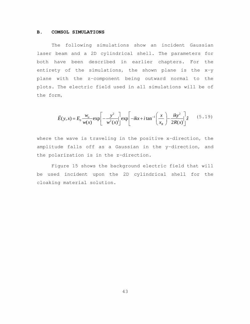
B. COMSOL SIMULATIONS
The following simulations show an incident Gaussian
laser beam and a 2D cylindrical shell. The parameters for
both have been described in earlier chapters. For the
entirety of the simulations, the shown plane is the x-y
plane with the z-component being outward normal to the
plots. The electric field used in all simulations will be of
the form,
(5.19)
where the wave is traveling in the positive x-direction, the
amplitude falls off as a Gaussian in the y-direction, and
the polarization is in the z-direction.
Figure 15 shows the background electric field that will
be used incident upon the 2D cylindrical shell for the
cloaking material solution.

44
Figure 15. Shows the incident electric Gaussian beam which is used in the simulations.
Now that the field is set up, we need to apply the
cloaking parameters to the shell, and test the theoretical
material solution viability of our designed shell. After
applying the properties to the shell and simulating the
results, the following figures display the results.

45
Figure 16. Z-component of the resulting electric field for the 2D cloaked cylindrical shell.
Figure 17. Electric field magnitude for the 2D cloaked cylindrical shell.
46
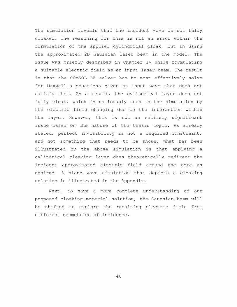
The simulation reveals that the incident wave is not fully
cloaked. The reasoning for this is not an error within the
formulation of the applied cylindrical cloak, but in using
the approximated 2D Gaussian laser beam in the model. The
issue was briefly described in Chapter IV while formulating
a suitable electric field as an input laser beam. The result
is that the COMSOL RF solver has to most effectively solve
for Maxwell's equations given an input wave that does not
satisfy them. As a result, the cylindrical layer does not
fully cloak, which is noticeably seen in the simulation by
the electric field changing due to the interaction within
the layer. However, this is not an entirely significant
issue based on the nature of the thesis topic. As already
stated, perfect invisibility is not a required constraint,
and not something that needs to be shown. What has been
illustrated by the above simulation is that applying a
cylindrical cloaking layer does theoretically redirect the
incident approximated electric field around the core as
desired. A plane wave simulation that depicts a cloaking
solution is illustrated in the Appendix.
Next, to have a more complete understanding of our
proposed cloaking material solution, the Gaussian beam will
be shifted to explore the resulting electric field from
different geometries of incidence.

47
Figure 18. Shifted 0.05 cm. Z-component of the electric field for the 2D cloaked cylindrical shell.
Figure 19. Shifted 0.05 cm. Electric field magnitude for the 2D cloaked cylindrical shell.
48
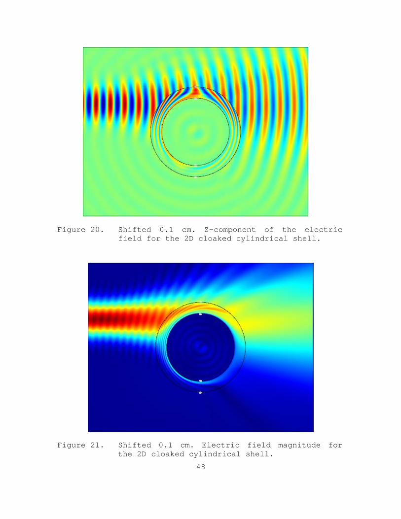
Figure 20. Shifted 0.1 cm. Z-component of the electric field for the 2D cloaked cylindrical shell.
Figure 21. Shifted 0.1 cm. Electric field magnitude for the 2D cloaked cylindrical shell.

49
Figure 22. Shifted 0.15 cm. Z-component of the electric
field for the 2D cloaked cylindrical shell.
Figure 23. Shifted 0.15 cm. Electric field magnitude for
the 2D cloaked cylindrical shell.

50
The above figures illustrate that the proposed cloaking
material solution theoretically protects the core from the
modeled laser beam regardless of the offset from normal
incidence.
51
VI. CYLINDRICAL DEFLECTION MATERIAL SOLUTION
A. SOLUTION SETUP
The proposed material solution for a simple deflection
layer around the missile is the exact same model setup as
the cloaking problem formulation, with the exception that we
will be defining the material layer solution to have
material properties that are isotropic within the layer. The
COMSOL environment allows us to make these changes to our
existing models that were used in the previous chapter.
To get the best-proposed solution, we first use a plane
wave incident on the cylindrical shell to test the material
solution for various material properties, to ascertain which
values yield better deflection results for a proposed C-DEW
material solution. After selecting the best-proposed
solution parameters, we display the simulations using the
modeled laser at various beam incidences.
B. COMSOL SIMULATIONS
The following simulations show an incident plane wave
and a 2D cylindrical shell. Parameters are the same as in
previous chapters. With a plane wave, one can see the total
resultant field more clearly than when a Gaussian beam is
employed. Once optimal material properties are found, we
will return to using an incident Gaussian laser beam. Trial
and error is used to hone in on a preferred material
solution.
52
0 ˆ( , ) expE y x E ikx z
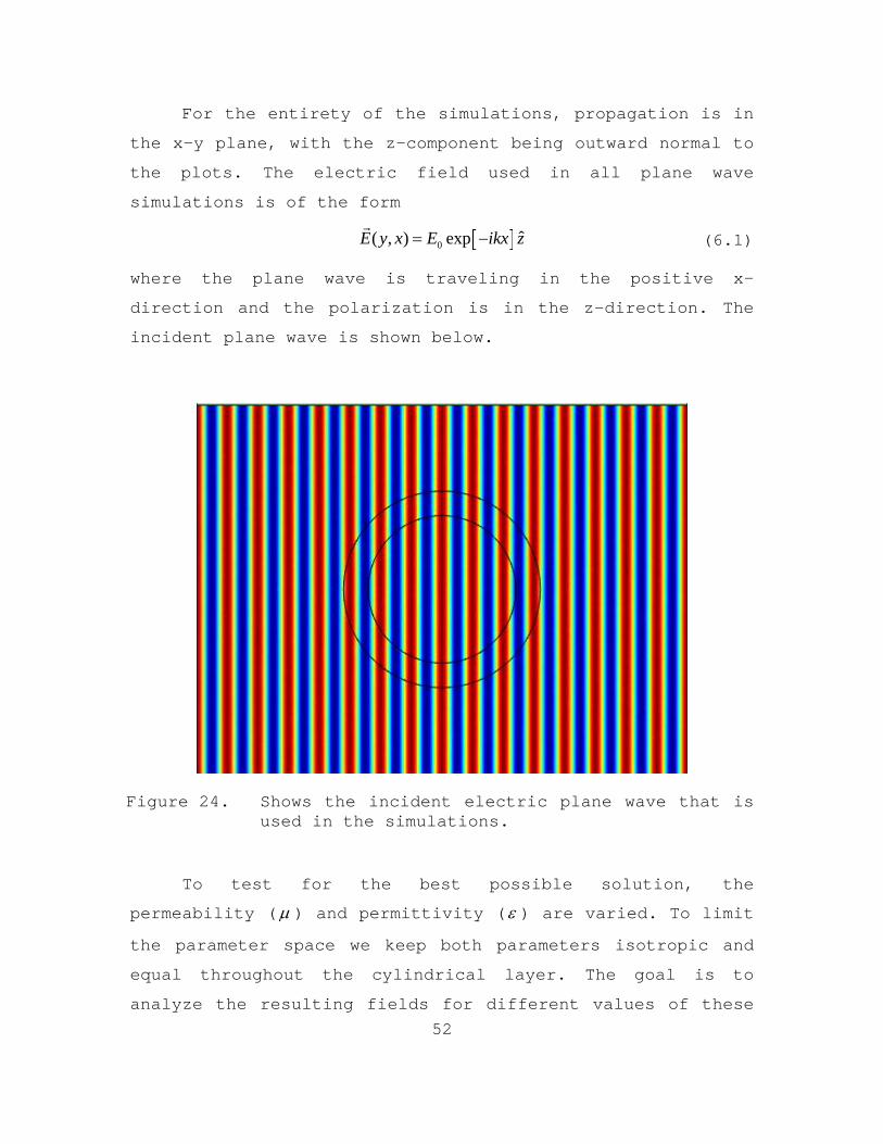
For the entirety of the simulations, propagation is in
the x-y plane, with the z-component being outward normal to
the plots. The electric field used in all plane wave
simulations is of the form
(6.1)
where the plane wave is traveling in the positive x-
direction and the polarization is in the z-direction. The
incident plane wave is shown below.
Figure 24. Shows the incident electric plane wave that is used in the simulations.
To test for the best possible solution, the
permeability ( ) and permittivity ( ) are varied. To limit
the parameter space we keep both parameters isotropic and
equal throughout the cylindrical layer. The goal is to
analyze the resulting fields for different values of these

53
parameters, and to determine which values would, in theory,
yield a better C-DEW material solution. Results are shown
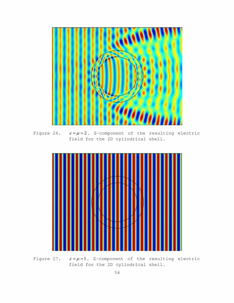
for various parameters for the cylindrical shell. The z-
component of the resulting electric field is shown as a
result of various proposed 2D deflection cylindrical shell
material solutions.
Figure 25. 3 . Z-component of the resulting electric field for the 2D cylindrical shell.
54
Figure 26. 2 . Z-component of the resulting electric field for the 2D cylindrical shell.
Figure 27. 1 . Z-component of the resulting electric field for the 2D cylindrical shell.

55
Figure 28. 0.5 . Z-component of the resulting electric field for the 2D cylindrical shell.
Figure 29. 0.1 . Z-component of the resulting electric field for the 2D cylindrical shell.

56
Figure 30. 0.01 . Z-component of the resulting electric field for the 2D cylindrical shell.
We can see that the best proposal for a deflective
material solution is one in which the permeability ( ) and
permittivity ( ) have values less than one and limiting
towards zero. The remainder of the simulations use the
modeled Gaussian laser beam, with 0.01 , to explore the
fields resulting from the cylindrical shell at various
incidences.
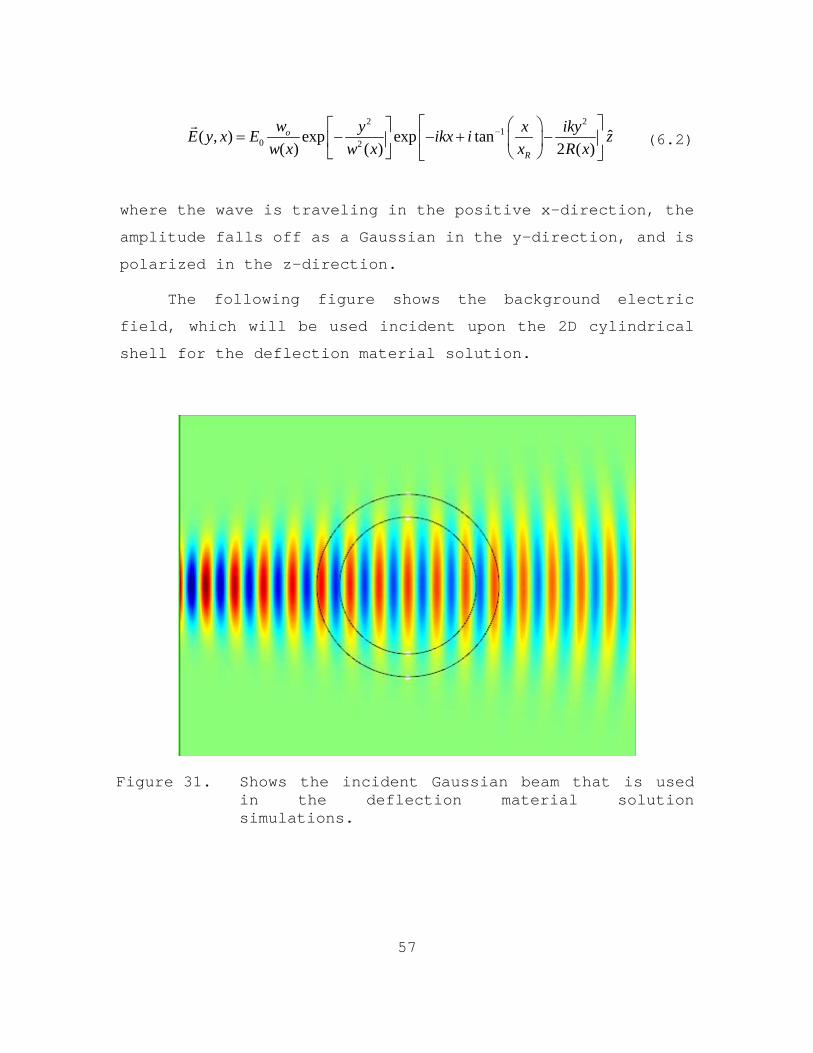
The following simulations show an incident Gaussian
laser beam and a 2D cylindrical shell. The parameters for
both have been described in earlier chapters. For the
entirety of the simulations, the shown plane is the x-y
plane, with the z-component being outward normal to the
plots. The electric field used in all simulations will be of
the form,
57
2 21
0 2ˆ( , ) exp exp tan
( ) ( ) 2 ( )o
R
w y x ikyE y x E ikx i z
w x w x x R x
(6.2)
where the wave is traveling in the positive x-direction, the
amplitude falls off as a Gaussian in the y-direction, and is
polarized in the z-direction.
The following figure shows the background electric
field, which will be used incident upon the 2D cylindrical
shell for the deflection material solution.
Figure 31. Shows the incident Gaussian beam that is used in the deflection material solution simulations.

58
Next, the following figure shows the results of the
simulation for the incident Gaussian laser beam incident
upon the cylindrical shell material solution for the values
of 0.01 .
Figure 32. 0.01 . Resulting electric field magnitude for the 2D cylindrical shell.
As expected from the above plane wave simulations, the
deflection material solution is able to mostly protect the
inner core from the incident electric field radiation under
normal incidence.
Next, to have a more complete understanding of our
proposed deflection material solution, the Gaussian beam
will be shifted so that we can explore the resulting fields
from different geometries of incidence.

59
Figure 33. 0.01 . Shifted 0.05 cm. Resulting electric field magnitude for the 2D cylindrical shell.
Figure 34. 0.01 . Shifted 0.1 cm. Resulting electric field magnitude for the 2D cylindrical shell.
60
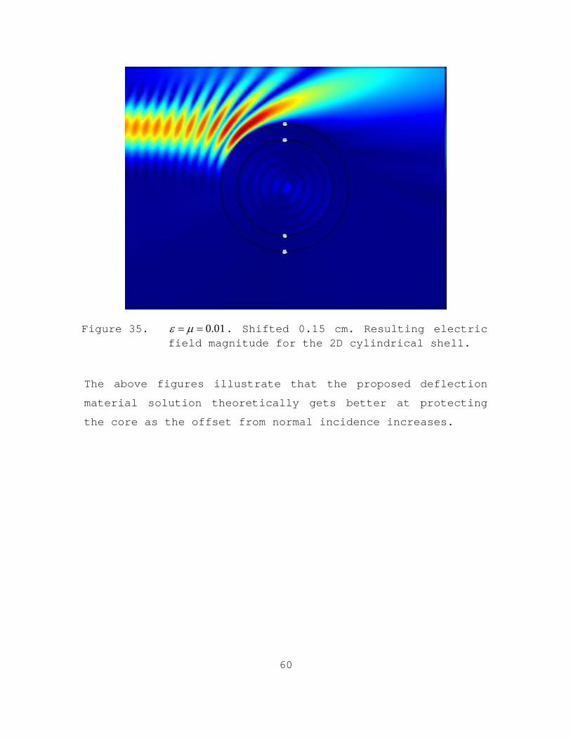
Figure 35. 0.01 . Shifted 0.15 cm. Resulting electric field magnitude for the 2D cylindrical shell.
The above figures illustrate that the proposed deflection
material solution theoretically gets better at protecting
the core as the offset from normal incidence increases.

61
VII. CONCLUSIONS
A. FINDINGS
The COMSOL Multiphysics package proved to be an
invaluable tool for simulating the theoretical idea of using
metamaterials as a proposed material solution to the problem
of C-DEW defense in the specific case of a high-energy
electromagnetic weapon. The purpose of this thesis was to
set up the entire problem from start to finish, and then
model it using the COMSOL environment. That goal was most
certainly met, and I believe, through the simulation
findings, there has been a definite case made for further
research in the area.
The simulations for the proposed cloaking material
solution did not illustrate a perfect cloak by the layer as
a result of the approximated electric field used as an
input. However, due to the nature of the problem and the
results desired, this was not necessary to show. The
difference between the simulations in this thesis and what
is prevalent in current research on cloaking, is the
application for which the cloak would be used. Near perfect
invisibility is not necessary for the present application.
In C-DEW defense, the main goal is to build a material
solution that would protect an asset from a DEW threat.
Analyzing the simulation plots shows that for the proposed
cloaking material solution, the cloaking layer was able to
redirect electromagnetic radiation incident upon the
cylinder through the cloaking layer, and away from the core
62
at various incidences. The simulation plots provide a great
pictorial view of the resulting theoretical effectiveness of
such a material solution.
As for the proposed deflection material solution, one
can also see from the simulations that by tuning the
permeability ( ) and permittivity ( ) towards unnaturally
occurring small values, one arrives at a solution in which a
material could be manufactured as a skin layer capable of
deflecting the radiation away from the core, and more
importantly, the entire missile. The advantage of such a
material solution, when compared to a cloaking layer, is
that there is less radiation penetration into the missile.
Radiation penetration within the defensive material layer
needs to be minimized in order to reduce energy conversion
to heat.
From a completely theoretical sense, both material
solutions seem to have promise. Both material solutions have
been shown in the simulations to redirect electromagnetic
radiation away from sensitive components in a cylindrical
geometry. However, in protecting from an actual C-DEW
threat, future realistic feasibility studies relating to the
construction and viability under intense radiation of such
metamaterials will need to be discussed further.
B. MATERIAL SOLUTIONS LIMITATIONS
Both material solutions have their limits. This thesis
is grounded upon a very basic research emphasis towards an
interest of the ONR. While hypothetical, the problem is
likely to develop and will require further research in
various fields of physics, engineering, and material

63
science. Constraints, have been glossed over, in defining
our models, and some have yet to be discussed, but must be
addressed. While the theoretical solutions presented look
highly interesting, there are realistic limitations.
Addressing some of these concerns is a good next step.
Knowledge of these challenges and the viability of the
material solutions presented must be based on actual real
world constraints.
The challenges of finding usable solutions to the
material solutions are considerable. A proposed FEL weapon
would project energy on the order of a megawatt. Currently,
metamaterials are very “lossy.” It means that a lot of the
energy travelling through the layer will be absorbed as
heat. A cloaking material solution would be affected by this
considerably. Further research will need to be done in
engineering highly efficient metamaterials that are capable
of withstanding significant amounts of heat energy before
one could ever imagine a cloaking metamaterial layer that
could redirect a high-energy laser beam such as a FEL.
Further problems arise in the complexity of metamaterial
construction given that with a cloaking layer six parameters
must be tailor-fit, and are continuously changing throughout
the layer. A third limitation of the cloaking solution for
C-DEW defense is that the entire cloak is typically designed
for a very specific wavelength of incident radiation. One of
the design features of a FEL, as was previously stated, is
its tuning ability. Changing the incident frequency could
therefore render a non-variable cloaking layer ineffective
to all but a very narrow band of frequencies. Cloaking is a
very interesting and exciting topic, but, in C-DEW defense,
due to the material anisotropic constraints, current

64
metamaterial inefficiencies, and the narrow band gap of
effectiveness, I do not think it is a technique worthy of
further research.
As for a deflection material solution, there are limits
as well. Again, manufacturing of complex material structures
is difficult, and that is why, for simplicity the proposed
material solution parameters were kept isotropic and equal
throughout. The advantage of a deflective medium solution is
that radiation energy passing through any part of the
cylinder would be minimized. Keeping high-energy radiation
out of the cylinder, is, by far, the more logical step
towards envisioning a possible C-DEW material solution.
Again, with such a metamaterial solution, one concludes that
metamaterials are designed for a narrow band of frequencies.
With the solution presented, however, one could imagine a
material solution layer being composed of cylindrical shells
of various metamaterial configurations, to better defend
against a wider band of frequencies.
In the end, both metamaterial solutions have
theoretical viability, which has been demonstrated by the
COMSOL simulations presented in this thesis. However, at
present time metamaterial efficiency, manufacturing
techniques, and most importantly, narrow band effectiveness
limits their potential for use towards the problem of C-DEW
defense. However, I do think that further research into an
isotropic shell composed of various metamaterial
configurations is worth researching and eventually testing
using a high-energy laser. Research into the actual

65
empirical bandwidth size for certain types of metamaterial
configurations would give a conclusive determination of
viability.

66
THIS PAGE INTENTIONALLY LEFT BLANK

67
APPENDIX. MODELING AND SIMULATION TUTORIAL FOR COMSOL 4.0
MODEL WIZARD 1. Start COMSOL by double-clicking its icon on the desktop. 2. When the Model Wizard opens, select the 2D space dimension. Click the Next button to continue to the Physics page. 3. In the Add Physics step, click the Radio Frequency folder, right-click Electromagnetic Waves (emw) and Add Selected. Click the Next button . 4. The last Model Wizard step is to select Study Type. Select the Boundary Mode Analysis study type and click the Finish button . GLOBAL DEFINITIONS 5. Right-click Global Definitions and select Parameters to create a list of parameters. In the Parameters field enter the following: Name Expression Description lam 0.05[m] Wavelength freq c_const/lam Frequency per_R 0.25 Material Sol. Thickness Coefficient R2 0.16[m] Outer Cylinder Radius R1 R2*(1-per_R) Inner Cylinder Radius VARIABLES 6. Under the Model 1 (mod1) tree, Right-click Definitions and select Variables to create a list of variables to be used for both the cloak and isotropic material solutions. Enter the list below in the appropriate fields. Name Expression r sqrt(x^2+y^2) phi atan(y/x) e_r (r-R1)/r
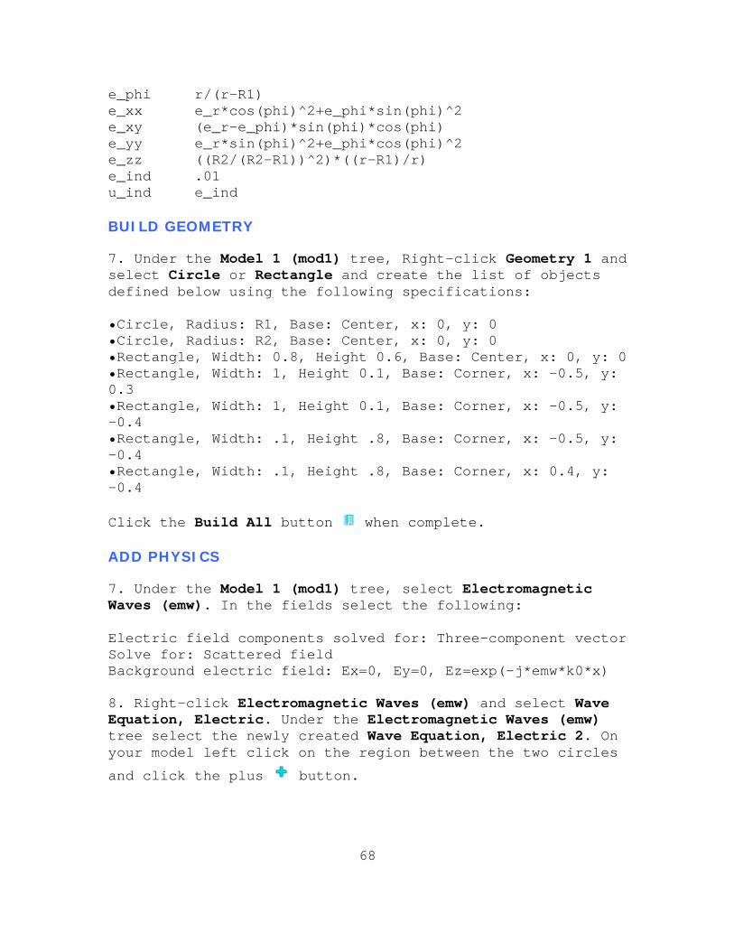
68
e_phi r/(r-R1) e_xx e_r*cos(phi)^2+e_phi*sin(phi)^2 e_xy (e_r-e_phi)*sin(phi)*cos(phi) e_yy e_r*sin(phi)^2+e_phi*cos(phi)^2 e_zz ((R2/(R2-R1))^2)*((r-R1)/r) e_ind .01 u_ind e_ind BUILD GEOMETRY 7. Under the Model 1 (mod1) tree, Right-click Geometry 1 and select Circle or Rectangle and create the list of objects defined below using the following specifications: •Circle, Radius: R1, Base: Center, x: 0, y: 0 •Circle, Radius: R2, Base: Center, x: 0, y: 0 •Rectangle, Width: 0.8, Height 0.6, Base: Center, x: 0, y: 0 •Rectangle, Width: 1, Height 0.1, Base: Corner, x: -0.5, y: 0.3 •Rectangle, Width: 1, Height 0.1, Base: Corner, x: -0.5, y: -0.4 •Rectangle, Width: .1, Height .8, Base: Corner, x: -0.5, y: -0.4 •Rectangle, Width: .1, Height .8, Base: Corner, x: 0.4, y: -0.4 Click the Build All button when complete. ADD PHYSICS 7. Under the Model 1 (mod1) tree, select Electromagnetic Waves (emw). In the fields select the following: Electric field components solved for: Three-component vector Solve for: Scattered field Background electric field: Ex=0, Ey=0, Ez=exp(-j*emw*k0*x) 8. Right-click Electromagnetic Waves (emw) and select Wave Equation, Electric. Under the Electromagnetic Waves (emw) tree select the newly created Wave Equation, Electric 2. On your model left click on the region between the two circles
and click the plus button.

69
9. Now for this layer we want to setup the material properties for either material solution (pick one or the other). Deflecting Material Solution Specifications:

70
Cloaking Material Solution Specifications:
10. Right-click Electromagnetic Waves (emw) and select Perfectly Matched Layers. Select all the outer boundary squares and rectangles in your model by shift clicking them.
After selecting all of them click the plus button in the Domain field.

71
11. Next, under the Perfectly Matched Layers tab, select Wave Equation, Electric 1. And set the following values for the layers.
As you should notice these values constitute the values that define a vacuum. We will use these same values again in the next step. 12. Under the Electromagnetic Waves (emw) tree select the Wave Equation, Electric 1. All that should be left selected is everything other than the material layer and the outer Perfectly Matched Layers. Set the same vacuum parameters from the previous step. 13. Right-click the Electromagnetic Waves (emw) and select Scattering Boundary Condition. Select all the very outer
most line segments on the model and click the plus button. MESHING 14. Under the Mesh 1 tab select Size. Set the following: Element Size: Custom Maximum Element Size: lam/8
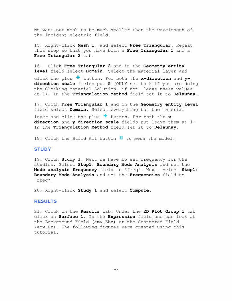
72
We want our mesh to be much smaller than the wavelength of the incident electric field. 15. Right-click Mesh 1, and select Free Triangular. Repeat this step so that you have both a Free Triangular 1 and a Free Triangular 2 tab. 16. Click Free Triangular 2 and in the Geometry entity level field select Domain. Select the material layer and
click the plus button. For both the x-direction and y-direction scale fields put 5 (ONLY set to 5 if you are doing the Cloaking Material Solution, if not, leave these values at 1). In the Triangulation Method field set it to Delaunay. 17. Click Free Triangular 1 and in the Geometry entity level field select Domain. Select everything but the material
layer and click the plus button. For both the x-direction and y-direction scale fields put leave them at 1. In the Triangulation Method field set it to Delaunay. 18. Click the Build All button to mesh the model. STUDY 19. Click Study 1. Next we have to set frequency for the studies. Select Step1: Boundary Mode Analysis and set the Mode analysis frequency field to "freq". Next, select Step1: Boundary Mode Analysis and set the Frequencies field to "freq". 20. Right-click Study 1 and select Compute. RESULTS 21. Click on the Results tab. Under the 2D Plot Group 1 tab click on Surface 1. In the Expression field one can look at the Background Field (emw.Ebz) or the Scattered Field (emw.Ez). The following figures were created using this tutorial.

73
Incident Electric Field
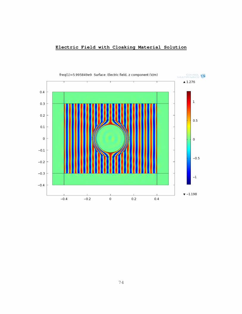
74
Electric Field with Cloaking Material Solution

75
Electric Field with Isotropic Material Solution

76
THIS PAGE IS INTENTIONALLY LEFT BLANK

77
LIST OF REFERENCES
[1] Jefferson Lab, “The FEL Program at Jefferson Lab,” http://www.jlab.org/FEL/ (last accessed 28 July 2010).
[2] Office of Naval Research, “Directed Energy
Program,” http://www.onr.navy.mil/Science-Technology/Departments/Code-35/All-Programs/air-warfare-352/Directed-Energy.aspx (last accessed 28 July 2010).
[3] Office of Naval Research, “Free Electron Laser,” http://www.onr.navy.mil/Media-Center/Fact-
Sheets/Free-Electron-Laser.aspx (last accessed 28 July 2010).
[4] R. K. Ackerman, “Fleet Defense Eyes Lasers,”
December 2003, http://www.afcea.org/signal/articles/templates/SIGNAL_Article_Template.asp?articleid=55&zoneid=22 (last accessed 29 July 2010).
[5] Office of Naval Research, “Counter Directed Energy
Program,” http://www.onr.navy.mil/en/Science-Technology/Departments/Code-35/All-Programs/aerospace-research-351/Counter-Directed-Energy.aspx (last accessed 02 August 2010).
[6] J. B. Pendry, D. Schurig, D. R. Smith,
“Controlling Electromagnetic Fields,” Science, vol. 312, no. 5781, pp. 1780-1782, June 2006.
[7] J. B. Pendry, “Metamaterials and the Control of
Electromagnetic Fields,” Optical Society of America Technical Digest, 2007.
[8] O. Hess, “Optics: Farewell to Flatland,” Nature,
vol. 455, no. 7211, pp. 299-300, September 2008. [9] P. H. Tichit, B. Kante, A. de Lustrac, “Design of
polygonal and elliptical invisibility cloaks,” Preeceedings of Nato ARW and META08, Marrakesh-Morocco, pp. 120-125, 7-10 May 2008.

78
[10] D. Schurig, J. B. Pendry, D. R. Smith, “Calculation of Material Properties and Ray Tracing in Transformation Media,” Optics Express, vol. 14, no. 21, pp. 9794-9804, October 2006.
[11] Science, “Supporting Online Material for
Controlling Electromagnetic Fields,” http://www.sciencemag.org/cgi/content/full/1125907/DC1 (last accessed 11 August 2010).
[12] M. Rahm, D. Schurig, D. A. Roberts, S. A. Cummer,
D.R. Smith, “Design of Electromagnetic Cloaks and Concentrators Using Form-Invariant Coordinate Transformations of Maxwell’s Equations,” Photon. Nanostruct. Fundam. Appl., vol. 6, is. 1, pp. 87-95, April 2008.
[13] J. M. Jouvard, A. Soveja, N. Pierron, “Thermal
Modelling of Metal Surface Texturing by Pulsed Laser,” Excerpt from the Proceedings of the COMSOL Users Conference, Paris, 2006.
[14] J. Alda, “Laser and Gaussian Beam Prorogation and
Transformation,” Encyclopedia of Optical Engineering, p. 999, 2003.
[15] Encyclopedia of Laser Physics and Technology,
“Gaussian Beams,” http://www.rp-photonics.com/ gaussian_beams.html (last accessed 20 August 2010).
[16] Absolute Astronomy, “Gaussian Beam,”
http://www.absoluteastronomy.com/topics/Gaussian_beam (last accessed 20 August 2010).
[17] Wikipedia, “Boeing AGM-84 Harpoon,”
http://en.wikipedia.org/wiki/Boeing_AGM-84_Harpoon (last accessed 01 September 2010).
[18] Boeing, “Boeing: Harpoon Overview,”
http://www.boeing.com/defense-space/missiles/harpoon/index.htm (last accessed 01 September 2010).
79
INITIAL DISTRIBUTION LIST
1. Defense Technical Information Center Ft. Belvoir, VA
2. Dudley Knox Library Naval Postgraduate School Monterey, CA
3. Professor Andres Larraza Naval Postgraduate School Monterey, CA
4. Professor Carlos F. Borges Naval Postgraduate School Monterey, CA
5. Professor James H. Luscombe Naval Postgraduate School Monterey, CA
6. Professor Brett Borden
Naval Postgraduate School Monterey, CA
7. Professor Clyde L. Scandrett Naval Postgraduate School Monterey, CA
8. LT Alex B. Baynes Naval Postgraduate School Monterey, CA