natural perspective projections for head-mounted · pdf filenatural perspective projections...
TRANSCRIPT
NATURAL PERSPECTIVE PROJECTIONS FOR HEAD-MOUNTED DISPLAYS 1
Natural Perspective Projections forHead-Mounted Displays
Frank Steinicke, Member, IEEE , Gerd Bruder, Student Member, IEEE ,Scott Kuhl, Member, IEEE , Pete Willemsen, Member, IEEE ,
Markus Lappe, and Klaus H. Hinrichs Member, IEEE
Abstract—The display units integrated in todays head-mounted displays (HMDs) provide only a limited field of view (FOV) to the virtualworld. In order to present an undistorted view to the virtual environment (VE), the perspective projection used to render the VE hasto be adjusted to the limitations caused by the HMD characteristics. In particular, the geometric field of view (GFOV), which definesthe virtual aperture angle used for rendering of the 3D scene, is set up according to the display field of view (DFOV). A discrepancybetween these two fields of view distorts the geometry of the VE in a way that either minifies or magnifies the imagery displayed to theuser. It has been shown that this distortion has the potential to affect a user’s perception of the virtual space, sense of presence, andperformance on visual search tasks.In this article we analyze the user’s perception of a VE displayed in a HMD, which is rendered with different GFOVs. We introducea psychophysical calibration method to determine the HMD’s actual field of view, which may vary from the nominal values specifiedby the manufacturer. Furthermore, we conducted two experiments to identify perspective projections for HMDs, which are identifiedas natural by subjects—even if these perspectives deviate from the perspectives that are inherently defined by the DFOV. In the firstexperiment, subjects had to adjust the GFOV for a rendered virtual laboratory such that their perception of the virtual replica matchedthe perception of the real laboratory, which they saw before the virtual one. In the second experiment, we displayed the same virtuallaboratory, but restricted the viewing condition in the real world to simulate the limited viewing condition in a HMD environment. Wefound that subjects evaluate a GFOV as natural when it is larger than the actual DFOV of the HMD—in some cases up to 50%—evenwhen subjects viewed the real space with a limited field of view.
Index Terms—Virtual reality, head-mounted displays, field of view.
F
1 INTRODUCTION
V IRTUAL reality (VR) environments provide the mostsophisticated technology for human-computer in-
terfaces developed so far. Because VR systems are ableto present information as seen from a user’s perspective,they have great potential as an enabling technology forimmersive exploration in many domains, for instancethey enable architects and engineers to experience virtualmodels at true scale. In general, for such systems oneis often concerned with representing three-dimensionalobjects on a two-dimensional display screen.
1.1 Head-Mounted Displays
Immersive virtual environments (VEs) are often charac-terized by head-mounted displays (HMD) and a trackingsystem for measuring a user’s position and orientation.Such head- or helmet-mounted displays are head-worndevices, which consist of either one or two small dis-plays with lenses and semi-transparent mirrors that are
• Frank Steinicke and Gerd Bruder are with the Visualization and ComputerGraphics (VisCG) Research Group, University of Munster, Germany, E-mail: {fsteini|g brud01}@uni-muenster.de.
• Jason Jerald is with the Effective Virtual Environments Group, UNC atChapel Hill, USA, E-mail: [email protected].
• Harald Frenz and Markus Lappe are with the Psychology Depart-ment II, University of Munster, Germany, E-mail: {frenzh|mlappe}@uni-muenster.de
embedded in eye-glasses, a helmet, or a visor. Theseminiaturized display units consist of CRTs, LCDs, LiquidCrystal on Silicon, or OLEDs. Some vendors employmultiple micro-displays to increase the total resolutionand display field of view. Applications can differ inwhether HMDs display computer-generated images, im-ages from the real world captured by cameras attachedto the HMD, or a combination of both as used inaugmented reality or mixed reality environments. Themost rudimentary HMDs provide only an image whichis not linked to a tracking system, i. e., the wearer’s headposition and orientation do not change the virtual view.However, most HMDs are commonly equipped with atracking system, which measures the HMD’s positionand orientation. This information can be used to updatethe view of the virtual world according to the HMD’sactual movements. This allows users to “look around” ina VR environment similar to the real world, i. e., turningthe head leads to a rotation of the virtual camera withoutthe need for additional input devices. In the scope of thispaper we focus on immersive VEs and consider HMDsthat display computer-generated images with respect toa user’s head motions.
1.2 Geometric and Display Field of View
Besides high resolution one of the most often namedrequirements for a HMD is a large field of view (FOV).
NATURAL PERSPECTIVE PROJECTIONS FOR HEAD-MOUNTED DISPLAYS 2
DFOV GFOV
near
far
eye distance
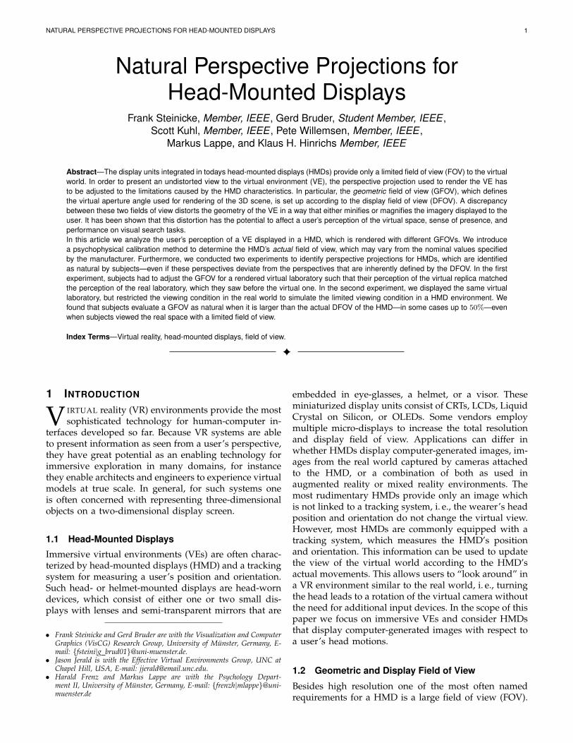
Fig. 1. Illustration of the relationship between (left) theDFOV of a HMD and (right) the GFOV used for perspec-tive rendering. Together with the near and far plane theGFOV define the perspective view frustum.
This FOV refers to the horizontal and vertical anglessubtended by the display–sometimes referred to as dis-play field of view (DFOV) (see Figure 1 (left)). Usuallya larger DFOV results in a greater sense of immersionand better situational awareness. However, most HMDsdo not cover the entire visual field of the human eyesand support only a considerably smaller field of view.Commercially available HMDs typically have fields ofview which range from 20 to 80 degrees diagonally–some even up to 150 degrees horizontal, whereas theeffective visual field of humans is approximately 200degrees horizontally and 150 degrees vertically [40]. Inorder for a virtual world to be displayed on a HMD, thecomputer graphics system must determine which partof the VE is to be viewed by the user.
In contrast to the DFOV, the geometric field of view(GFOV) defines the horizontal and vertical boundariesof the virtual viewing volume along with the aspectratio (see Figure 1 (right).) With such a setup, usermovements measured by the tracker are mapped to theposition and orientation of the virtual camera. Usually,tracked head pose changes applied to the virtual cameraby means of a one-to-one mapping define the camera’sposition and orientation in the VE; the projection ofthe virtual camera defines the view frustum. In mostVR applications a perspective projection is chosen suchthat depth cues are consistent with a user’s real-worldview. Near and far clipping planes define the bounds ofthe visible scene. The horizontal and vertical geometricfields of view define the angles subtended by the view-port from the center of projection in virtual space or,equivalently, the angle subtended by the camera’s viewfrustum. As illustrated in Figure 1 (right) usually on-axisstereographic rendering is applied in HMD conditions.The image projected onto the viewport is displayed onboth physical screens of the HMD.
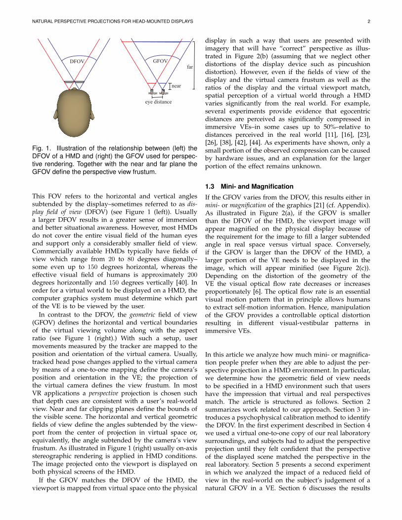
If the GFOV matches the DFOV of the HMD, theviewport is mapped from virtual space onto the physical
display in such a way that users are presented withimagery that will have “correct” perspective as illus-trated in Figure 2(b) (assuming that we neglect otherdistortions of the display device such as pincushiondistortion). However, even if the fields of view of thedisplay and the virtual camera frustum as well as theratios of the display and the virtual viewport match,spatial perception of a virtual world through a HMDvaries significantly from the real world. For example,several experiments provide evidence that egocentricdistances are perceived as significantly compressed inimmersive VEs–in some cases up to 50%–relative todistances perceived in the real world [11], [16], [23],[26], [38], [42], [44]. As experiments have shown, only asmall portion of the observed compression can be causedby hardware issues, and an explanation for the largerportion of the effect remains unknown.
1.3 Mini- and Magnification
If the GFOV varies from the DFOV, this results either inmini- or magnification of the graphics [21] (cf. Appendix).As illustrated in Figure 2(a), if the GFOV is smallerthan the DFOV of the HMD, the viewport image willappear magnified on the physical display because ofthe requirement for the image to fill a larger subtendedangle in real space versus virtual space. Conversely,if the GFOV is larger than the DFOV of the HMD, alarger portion of the VE needs to be displayed in theimage, which will appear minified (see Figure 2(c)).Depending on the distortion of the geometry of theVE the visual optical flow rate decreases or increasesproportionately [6]. The optical flow rate is an essentialvisual motion pattern that in principle allows humansto extract self-motion information. Hence, manipulationof the GFOV provides a controllable optical distortionresulting in different visual-vestibular patterns inimmersive VEs.
In this article we analyze how much mini- or magnifica-tion people prefer when they are able to adjust the per-spective projection in a HMD environment. In particular,we determine how the geometric field of view needsto be specified in a HMD environment such that usershave the impression that virtual and real perspectivesmatch. The article is structured as follows. Section 2summarizes work related to our approach. Section 3 in-troduces a psychophysical calibration method to identifythe DFOV. In the first experiment described in Section 4we used a virtual one-to-one copy of our real laboratorysurroundings, and subjects had to adjust the perspectiveprojection until they felt confident that the perspectiveof the displayed scene matched the perspective in thereal laboratory. Section 5 presents a second experimentin which we analyzed the impact of a reduced field ofview in the real-world on the subject’s judgement of anatural GFOV in a VE. Section 6 discusses the results
NATURAL PERSPECTIVE PROJECTIONS FOR HEAD-MOUNTED DISPLAYS 3
(a) gF = 0.8 (b) gF = 1.0 (c) gF = 1.2
Fig. 2. Illustration of different perspective projections in a virtual 3D model of our laboratory: with a GFOV (a) largerthan (b) identical to and (c) smaller than the DFOV. The top row shows the virtual laboratory and the camera frustumsfrom a top-down view, the bottom row shows the corresponding renderings of the laboratory with GFOVs which havebeen manipulated with gains of (a) gF = 0.8, (b) gF = 1.0 and (c) gF = 1.2.
of the experiments as well as implications about howto set up the virtual perspective in HMD environments.Section 7 concludes the paper and gives an overviewabout future work. Some of the results presented in thisarticle have been presented in [37].
2 RELATED WORK
It is a challenging task to project virtual objects ona planar display surface in such a way that metricproperties of objects are perceived correctly by humanobservers. In order to extract three-dimensional depth,size and shape cues about virtual objects from planarrepresentations, the human visual system combines var-ious different sources of information [27]. Since two-dimensional pictorial or monocular depth cues, e. g.,linear perspective, are interpreted by the visual systemas three-dimensional depth, the information they presentmay be ambiguous [18]. These ambiguities make it dif-ficult to extract correct depth cues and are intentionallyintroduced in many common optical illusions [9].
View Frustums
The perspective view frustum defines the three-dimensional volume in space, which is projected to theimage plane. As illustrated in Figure 1 (right), a viewfrustum can be specified in view space by the distancesof the near (near ∈ R+) and far (far ∈ R+) clippingplanes, and the extents of the projection area on the nearplane (left, right, top, bottom ∈ R) [35]. Alternatively, asymmetrical view frustum can be specified using onlythe vertical angle of the geometric field of view:
GFOV = 2 · atan
(top
near
)∈
]0, 180
[, (1)
and the image ratio (ratio ∈ R+).The nominal DFOV of a HMD can be derived by the
width (w) and the height (h) of the displays specifiedby the manufacturers, and the distance (d) of the eyesto the displays. Assuming a symmetrical view frustum,the vertical DFOV can be calculated with the followingequation:
DFOV = 2 · atan
(h
2 · d
), (2)
and the horizontal DFOV can be calculated by replacingh by w in equation (2).
Since most commercially available HMDs have rela-tively narrow fields of view in comparison to the effec-tive visual field of humans, HMD users can see only arather restricted portion of the virtual world if the GFOVmatches the DFOV of the HMD. In the real world, anarrow field of vision has been shown to degrade spatialawareness and human performance in navigation andmanipulation tasks [17], [13] as well as visual searchtasks [3]. There has been much evidence that a restrictedFOV in the virtual world may lead to perceptual, visual,and motor decrements in various kinds of performancetasks [1], [12].
Mini- and MagnificationAs mentioned in Section 1.2, if the GFOV matches theDFOV, the viewport is mapped directly from virtualspace onto the physical display, and therefore users
NATURAL PERSPECTIVE PROJECTIONS FOR HEAD-MOUNTED DISPLAYS 4
are presented with imagery that will have a “correct”perspective. However, a deviation between the GFOVand the DFOV occurs, for example, when the actualDFOV varies from the nominal values specified by theHMD manufacturers. A deviation can also be inducedintentionally. Sometimes VR application developers usea larger GFOV in order to provide a wider view tothe virtual world. Such deviations result in minificationof the graphics (cf. Appendix). Choosing an extremelylarge field of view may not always be optimal, sincethe required GFOV for a HMD mainly depends on theapplication under consideration. If the GFOV is largerthan the DFOV of the HMD, any given object drawnto the screen will cover fewer pixels in the screen asthe GFOV is increased. Furthermore, a large GFOV maybe unnecessary for tasks, which are localized within asmall spatial region of interest [13], and it may aggravatesimulator sickness effects, particularly those caused byvection and visual-vestibular mismatch [34], [36].
However, an increased GFOV allows for the inclusionof more information in the 3D view like a larger physicaldisplay would. A larger DFOV is essential in some ap-plications and has the potential to improve and increasethe user’s sense of presence [2], [34]. Similar benefits mayalso occur if a large GFOV is used with a display thathas a small DFOV. Several works have introduced thesedeviations in order to address limitations of small dis-play spaces in two-dimensional desktop environments,for example using Fish-Eye views [8].
Scene Perception
Mini- or magnification changes several visual cues thatprovide information about metric properties of objectssuch as distances, sizes, shapes and angles [18]. How-ever, even if the GFOV and DFOV match, people’s per-ceptions and actions in the VE may differ from their per-ceptions and actions in an equivalent real environment.Many studies that compared distance perception of statictargets in immersive VEs and in the real world foundevidence that distances are perceived as compressed inVEs relative to the real world [11], [26], [42], [43]. It hasbeen shown that as long as HMD users look aroundin a real or virtual environment, a restricted field ofview (e. g., a 60 degree diagonal DFOV) did not changetheir behavior on blind walking distance estimationtasks [4], [19]. However, previous studies have suggestedthat physical factors related to the ergonomics of head-mounted displays may account for some of the apparentcompression [19], [22], [21], [38], [41].
However, an explanation for the larger portion of theobserved compression effects remains unknown. Giventhat underestimation has been found in a number ofstudies using HMDs and that HMDs typically have areduced FOV, the restricted field of view has been sus-pected as a factor influencing distance perception [30],[43]. Increasing the GFOV of a VE may be one way tocompensate for the restricted DFOV.
Although researchers have investigated the effects ofthe GFOV on performance and level of presence experi-enced [15], few studies have explicitly considered the re-lationship between GFOV and the DFOV of HMDs [45].In the experiments described by Kuhl et al. [21] subjectssaw the virtual world with a FOV that was larger(20%) than the one provided by the HMD resulting inminification of the graphics. In this case, the typicalspatial compression effects in direct blind walking tasksin VEs were reduced, i. e., subjects walked significantlyfarther to previously seen targets when the graphicswere minified. On the other hand, magnification changesthese cues in the opposite direction and can potentiallydecrease perceived distance. The benefits of distortingthe GFOV are not clear [37]. A series of studies wereconducted to evaluate the role of the GFOV in accuratespatial judgments. It has been shown that when subjectsperceive proprioceptive and tactile feedback, the GFOVcan be increased without causing a significant distortionin the user’s distance perception [45]. Relative azimuthand elevation judgments in a perspective projection wereless accurate for GFOVs greater than the DFOV [25].This effect has been noted in see-through stereoscopicdisplays that match real-world viewing with syntheticelements [32]. Alternatively, room size estimation tasksand distance estimation tasks were aided by a largerGFOV [28]. The sense of presence also appears to belinked to an increased GFOV [14]. For other tasks, likeestimating the relative skew of two lines, a disparitybetween DFOV and GFOVs was less useful [33].
3 PSYCHOPHYSICAL CALIBRATION OF GFOVAs mentioned in Section 2, the DFOV of a HMD mayvary from the nominal values specified by the manu-facturer. In this section we describe a psychophysicalcalibration method for HMDs that allows to determinethe DFOV. Usually, the nominal DFOV for HMDs isspecified as visual angle across the diagonal of a display.1
Since most graphics systems require the horizontaland vertical (instead of the diagonal) fields of view ofthe display, almost all HMD users convert the nominaldiagonal DFOV into geometric horizontal and verticalfields of view, often assuming a square-pixel aspect ratio.However, according to Kuhl et al. [21], the horizontaland vertical geometric fields of view determined in sucha way can fail to match the DFOV of the HMD for threereasons:
1) The nominal diagonal DFOV may differ from thedisplay’s actual diagonal DFOV.
2) The actual aspect ratio of the display may notmatch the ratio of horizontal to vertical pixelcounts.
3) Pincushion distortion may lead to different FOVvalues.
1. For simplicity, we refer to GFOV and DFOV as the diagonal fieldsof view, if not stated otherwise.
NATURAL PERSPECTIVE PROJECTIONS FOR HEAD-MOUNTED DISPLAYS 5
In order to account for the three sources of error, differ-ent calibration methods have been proposed to identifythe DFOV of a HMD [24]. Ellis and Nemire [7], [29]displayed vertical poles in the HMD. When wearing theHMD, subjects had to point at the perceived location ofthe poles in the real world. This allowed the researchersto calculate how the GFOV has to be specified so thatthe virtual angles and pointed angles match. Anothermethod [31] uses a strobe light to provide subjects withan afterimage of a known visual angle. When wearingthe HMD, subjects used this afterimage to measure theFOV of the display. It may also be possible to calibratenon-see-through HMDs by adapting methods used forsee-through display calibration [10]. Another simple cal-ibration approach requires VR users to adjust the GFOVby comparing a real object with a virtual object byconstantly raising and lowering the HMD [21]. In the fol-lowing we describe a psychophysical calibration methodto identify the DFOV of a HMD in a more precise wayin comparison to previously described methods.
Psychophysics is an area of perceptual psychologythat employs specific behavioral methods to study therelation between stimulus intensity and perception re-ported by a human observer. The amount of change ina stimulus required to produce a noticeable sensationis defined as the just noticeable difference (JND). In thecalibration process discussed here, subjects had to reporttheir judgments of different GFOVs based on a two-alternative forced-choice task (2-AFCT). In order to manipu-late the GFOV we apply field of view gains gF [x] ∈ R+ andgF [y] ∈ R+ to the virtual camera frustum by replacingthe horizontal angle fovx and the vertical angle fovy ofthe geometric field of view by gF [x] · fovx and gF [y] · fovy,respectively.
In the psychophysical calibration process described inthis section, we used the method of constant stimuli,i. e., the presented stimuli were not related from onetrial to the next, but presented randomly and uniformlydistributed. After the visual stimuli had been presented,a participant had to choose between one of two possi-ble responses, i. e., “Do you think the virtual world isminified or magnified?”; responses like “I can’t tell.” werenot allowed. In this method, when the participant cannotdetect the signal, he must guess, and on average he willbe correct in 50% of the trials. Participants were trainedas to what “minified” and “magnified” means in thiscontext.
The gain at which a subject responds “minified” inhalf of the trials is taken as the point of subjective equality(PSE), at which the subject perceives both stimuli asidentical. As the gain decreases or increases from thisvalue the ability of the subject to detect a difference be-tween both stimuli increases, resulting in a psychometriccurve for the discrimination performance. Thresholds arethose points of intensity at which subjects can just de-tect a discrepancy between physical and virtual stimuli.Usually the points at which the curve reaches the middlebetween the chance level and 100% correct estimations
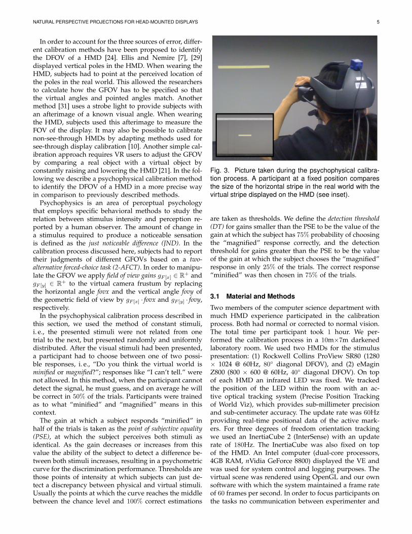
Fig. 3. Picture taken during the psychophysical calibra-tion process. A participant at a fixed position comparesthe size of the horizontal stripe in the real world with thevirtual stripe displayed on the HMD (see inset).
are taken as thresholds. We define the detection threshold(DT) for gains smaller than the PSE to be the value of thegain at which the subject has 75% probability of choosingthe “magnified” response correctly, and the detectionthreshold for gains greater than the PSE to be the valueof the gain at which the subject chooses the “magnified”response in only 25% of the trials. The correct response“minified” was then chosen in 75% of the trials.
3.1 Material and Methods
Two members of the computer science department withmuch HMD experience participated in the calibrationprocess. Both had normal or corrected to normal vision.The total time per participant took 1 hour. We per-formed the calibration process in a 10m×7m darkenedlaboratory room. We used two HMDs for the stimuluspresentation: (1) Rockwell Collins ProView SR80 (1280× 1024 @ 60Hz, 80◦ diagonal DFOV), and (2) eMaginZ800 (800 × 600 @ 60Hz, 40◦ diagonal DFOV). On topof each HMD an infrared LED was fixed. We trackedthe position of the LED within the room with an ac-tive optical tracking system (Precise Position Trackingof World Viz), which provides sub-millimeter precisionand sub-centimeter accuracy. The update rate was 60Hzproviding real-time positional data of the active mark-ers. For three degrees of freedom orientation trackingwe used an InertiaCube 2 (InterSense) with an updaterate of 180Hz. The InertiaCube was also fixed on topof the HMD. An Intel computer (dual-core processors,4GB RAM, nVidia GeForce 8800) displayed the VE andwas used for system control and logging purposes. Thevirtual scene was rendered using OpenGL and our ownsoftware with which the system maintained a frame rateof 60 frames per second. In order to focus participants onthe tasks no communication between experimenter and
NATURAL PERSPECTIVE PROJECTIONS FOR HEAD-MOUNTED DISPLAYS 6
participant was performed during the experiment. Theparticipants received instructions on slides presented onthe HMD. A Nintendo WII remote controller served asan input device via which the participant judged hiscomparison between virtual and real perspective.
The visual stimuli consisted of a virtual 3D modelof the real laboratory (see Figure 2). We modeled thisvirtual replica as a set of texture-mapped polygons. Thetexture maps were obtained from a mosaic of digitalphotographs of the walls, ceiling and floor of the labo-ratory. All floor and wall fixtures were represented trueto original as detailed, textured 3D objects, e. g., doorknobs, furniture and computer equipment.
During the calibration procedure, the participantsfaced a wall of the laboratory with their heads mountedin a fixed position at a distance of 3m from the wall (seeFigure 3). In the virtual world we displayed consecu-tively a horizontal respectively vertical 1m×0.05m stripeon the wall, in the real world we taped correspondingstripes onto the wall. The participants compared the real-world stripes with the stripes displayed in the HMD byrepeatedly raising and lowering the HMD on their head.Then the participants had to judge whether the virtualstripe was displayed minified or magnified comparedto the real-world stripe based on a 2-AFCT. We testedboth the ProView and the eMagin HMD with a horizon-tal and a vertical stripe consecutively. We manipulatedthe GFOV with different gains gF [x] and gF [y] rangingbetween 0.90 and 1.10 in steps of 0.01 applied to thehorizontal and vertical angles of the HMDs, which wecomputed from the diagonal DFOV specified by themanufacturers (cf. Appendix). We presented the gains inrandomized order, each gain occurring 10 times. Figure 3shows a participant in the physical laboratory, whocompares the horizontal virtual stripe in the 3D modelwith the stripe in the real world.
3.2 Results
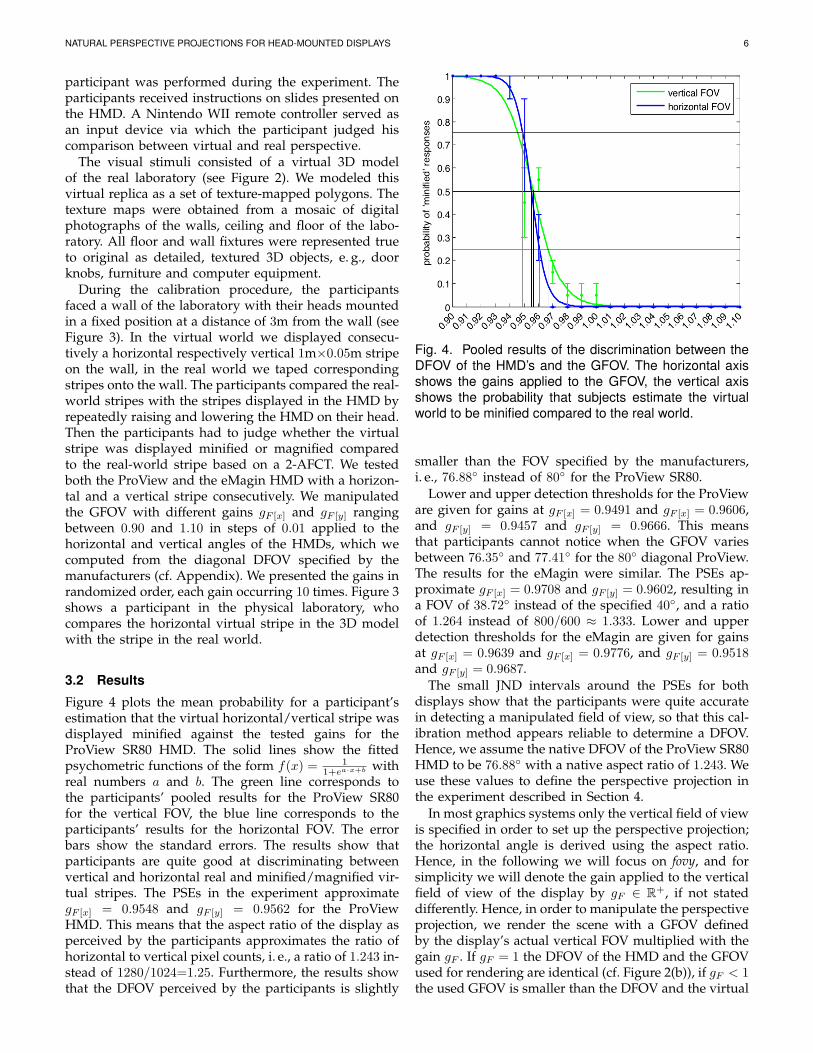
Figure 4 plots the mean probability for a participant’sestimation that the virtual horizontal/vertical stripe wasdisplayed minified against the tested gains for theProView SR80 HMD. The solid lines show the fittedpsychometric functions of the form f(x) = 1
1+ea·x+b withreal numbers a and b. The green line corresponds tothe participants’ pooled results for the ProView SR80for the vertical FOV, the blue line corresponds to theparticipants’ results for the horizontal FOV. The errorbars show the standard errors. The results show thatparticipants are quite good at discriminating betweenvertical and horizontal real and minified/magnified vir-tual stripes. The PSEs in the experiment approximategF [x] = 0.9548 and gF [y] = 0.9562 for the ProViewHMD. This means that the aspect ratio of the display asperceived by the participants approximates the ratio ofhorizontal to vertical pixel counts, i. e., a ratio of 1.243 in-stead of 1280/1024=1.25. Furthermore, the results showthat the DFOV perceived by the participants is slightly
Fig. 4. Pooled results of the discrimination between theDFOV of the HMD’s and the GFOV. The horizontal axisshows the gains applied to the GFOV, the vertical axisshows the probability that subjects estimate the virtualworld to be minified compared to the real world.
smaller than the FOV specified by the manufacturers,i. e., 76.88◦ instead of 80◦ for the ProView SR80.
Lower and upper detection thresholds for the ProVieware given for gains at gF [x] = 0.9491 and gF [x] = 0.9606,and gF [y] = 0.9457 and gF [y] = 0.9666. This meansthat participants cannot notice when the GFOV variesbetween 76.35◦ and 77.41◦ for the 80◦ diagonal ProView.The results for the eMagin were similar. The PSEs ap-proximate gF [x] = 0.9708 and gF [y] = 0.9602, resulting ina FOV of 38.72◦ instead of the specified 40◦, and a ratioof 1.264 instead of 800/600 ≈ 1.333. Lower and upperdetection thresholds for the eMagin are given for gainsat gF [x] = 0.9639 and gF [x] = 0.9776, and gF [y] = 0.9518and gF [y] = 0.9687.
The small JND intervals around the PSEs for bothdisplays show that the participants were quite accuratein detecting a manipulated field of view, so that this cal-ibration method appears reliable to determine a DFOV.Hence, we assume the native DFOV of the ProView SR80HMD to be 76.88◦ with a native aspect ratio of 1.243. Weuse these values to define the perspective projection inthe experiment described in Section 4.
In most graphics systems only the vertical field of viewis specified in order to set up the perspective projection;the horizontal angle is derived using the aspect ratio.Hence, in the following we will focus on fovy, and forsimplicity we will denote the gain applied to the verticalfield of view of the display by gF ∈ R+, if not stateddifferently. Hence, in order to manipulate the perspectiveprojection, we render the scene with a GFOV definedby the display’s actual vertical FOV multiplied with thegain gF . If gF = 1 the DFOV of the HMD and the GFOVused for rendering are identical (cf. Figure 2(b)), if gF < 1the used GFOV is smaller than the DFOV and the virtual
NATURAL PERSPECTIVE PROJECTIONS FOR HEAD-MOUNTED DISPLAYS 7
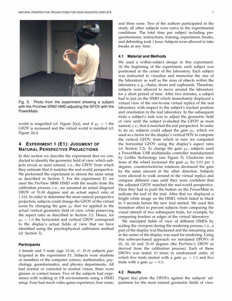
Fig. 5. Photo from the experiment showing a subjectwith the ProView SR80 HMD adjusting the GFOV with thePowerMate.
world is magnified (cf. Figure 2(a)), and if gF > 1 theGFOV is increased and the virtual world is minified (cf.Figure 2(c)).
4 EXPERIMENT 1 (E1): JUDGMENT OFNATURAL PERSPECTIVE PROJECTIONS
In this section we describe the experiment that we con-ducted to identify the geometric field of view, which sub-jects reveal as most natural, i. e., the GFOV from whichthey estimate that it matches the real-world perspective.We performed the experiment in almost the same setupas described in Section 3. For the experiment E1 weused the ProView SR80 HMD with the results from thecalibration process, i. e., we assumed an actual diagonalDFOV of 76.88 degrees and an actual aspect ratio of1.243. In order to determine the most natural perspectiveprojection, subjects could change the GFOV of the virtualscene by changing the gain gF that we applied to theactual vertical geometric field of view, while preservingthe aspect ratio as described in Section 3.2. Hence, forgF = 1.0 the horizontal and vertical GFOV correspondto the display’s actual fields of view that we haveidentified using the psychophysical calibration method(cf. Section 3).
Participants
2 female and 9 male (age 23-46, ∅: 28.8) subjects par-ticipated in the experiment E1. Subjects were studentsor members of the computer science, mathematics, psy-chology, geoinformatics, and physics departments. Allhad normal or corrected to normal vision; three woreglasses or contact lenses. Five of the subjects had expe-rience with walking in VR environments using a HMDsetup. Four had much video game experience, four some,
and three none. Two of the authors participated in thestudy, all other subjects were naıve to the experimentalconditions. The total time per subject including pre-questionnaire, instructions, training, experiment, breaks,and debriefing took 1 hour. Subjects were allowed to takebreaks at any time.
4.1 Material and MethodsWe used a within-subject design in this experiment.At the beginning of the experiment, each subject waspositioned in the center of the laboratory. Each subjectwas instructed to visualize and memorize the size ofthe laboratory as well as the sizes of objects within thelaboratory, e. g., chairs, doors and cupboards. Therefore,subjects were allowed to move around the laboratoryfor a short period of time. After two minutes, a subjecthad to put on the HMD which immediately displayed avirtual view of the one-to-one virtual replica of the reallaboratory with respect to the subject’s tracked positionand orientation in the real laboratory. In the subsequenttrials a subject’s task was to adjust the geometric fieldof view until the subject evaluated the GFOV as mostnatural, i. e., that it matched the real perspective. In orderto do so, subjects could adjust the gain gF , which weused as a factor for the display’s vertical FOV to computethe vertical GFOV, from which in turn we computedthe horizontal GFOV using the display’s aspect ratio(cf. Section 3.2). To change the gain gF , subjects useda PowerMate USB multimedia controller manufacturedby Griffin Technology (see Figure 5). Clockwise rota-tions of the wheel increased the gain gF by 0.01 per 3degrees, counterclockwise rotations decreased the gainby the same amount in the other direction. Subjectswere allowed to walk around in the virtual replica andcompare different cues until they were confident thatthe adjusted GFOV matched the real-world perspective.Then they had to push the button on the PowerMate toindicate the end of the trial. After that we displayed abright white image on the HMD, which faded to blackin 3 seconds before the new trial started. We used thistransition effect to prevent subjects from comparing thevisual stimuli of two subsequent trials, for example, bycomparing borders or edges of the virtual laboratory.
We simulated fields of view of different HMDs byscaling the viewport during the rendering process, i. e., apart of the display was blackened and the remaining areain the center of the display was used for rendering. Usingthis software-based approach we simulated DFOVs of20, 40, 60 and 76.88 degrees (the ProView’s DFOV asderived from the calibration process). Each of theseDFOVs was tested 10 times in randomized order, ofwhich five trials started with a gain gF = 1.5 and fivetrials with a gain gF = 0.5.
4.2 ResultsFigure 6(a) plots the DFOVs against the subjects’ ad-justment for the most natural geometric fields of view.

NATURAL PERSPECTIVE PROJECTIONS FOR HEAD-MOUNTED DISPLAYS 8
(a) (b)
Fig. 6. Pooled results of the experiment showing the different simulated displays’ fields of view on the horizontal axisplotted against (a) the absolute GFOVs and (b) the relative deviation of the GFOVs from the display’s FOV on thevertical axis.
Figure 6(b) shows the relative deviation of the GFOVsfrom the displays’ actual fields of view. The black cir-cles represent the PSEs, i. e., the GFOVs that subjectsperceived as natural. The error bars show the standarderrors pooled over all subjects. There was no differencebetween starting a trial with an initial gain gF = 1.5or gF = 0.5, so we pooled the results for these twoconditions. The results show that the subjects’ averagejudgment of a “natural” GFOV deviates significantlyfrom the actual display’s FOV, especially for small FOVs.The PSEs in the experiment are given at a diagonalgeometric field of view of 29.53◦ for a HMD with adiagonal DFOV of 20◦, 53.85◦ (40◦), 72.33◦ (60◦), and88.34◦ (76.88◦). The results show that the geometric fieldof view which appears most natural to the subjects islarger than the display’s field of view. In Figure 6(b) itis pointed out that subjects adjusted the GFOV approxi-mately 47.66% larger than the display’s field of view inthe case that the HMD’s DFOV equals 20◦. In the othercases the geometric fields of view were adjusted 34.63%(40◦), 20.55% (60◦), and 12.68% (78.4◦) larger than theDFOV.
From the subjects’ answers we computed lower andupper thresholds at the points of intensity around thePSEs where subjects answered with 75% probabilitythat the presented perspective projections were natural.These thresholds define a range of gains which appearnatural to users in 75% of the time. Hence, gains withinthis range can be applied in HMD environments withoutsubjects noticing a discrepancy between the display’sFOV and the GFOV used for rendering the VE. For aHMD with 20◦ diagonal field of view the lower and
upper thresholds for GFOVs are 23.40◦ and 34.20◦. Forthe other simulated fields of view the lower and up-per thresholds are 45.40◦ and 59.40◦ (40◦), 60.00◦ and80.40◦ (60◦), and 77.60◦ and 98.40◦ (78.4◦). The intervalsaround the PSEs for the different FOVs show that thesubjects’ judgment of a “natural” FOV shifts towardslarger GFOVs for HMDs with a small FOV. The resultsfurther show that the subjects’ judgment of a naturalGFOV approximates the DFOV for HMDs with a largerFOV. The results for the two expert users who performedthe calibration (as described in Section 3) did not varysignificantly from the other subjects.
In summary, the results motivate that the GFOVshould be increased for HMDs with a small geometricfield of view in order to appear more natural to users.Even when the geometric field of view is further in-creased within the gain interval of the detection thresh-olds the corresponding perspective projection appearsstill natural.
We measured the subjects’ self-reported sense of pres-ence in the displayed virtual world using the Slater-Usoh-Steed (SUS) presence questionnaire [39]. Subjectsrated their sense of presence on average with a SUSscore of 4.52. Subjects further judged the difficulty ofthe task with 0.75 on average on a 5-point Likert-scale (0corresponds to very easy, 4 corresponds to very difficult).On a comparable Likert-scale subjects reported their fearof colliding with physical objects during immersion onaverage as 0.5, which shows that subjects felt quite safe,probably because the virtual scene showed a co-locatedand detailed virtual replica of the subjects’ physicalsurroundings. Draper et al. [6] have reported increased
NATURAL PERSPECTIVE PROJECTIONS FOR HEAD-MOUNTED DISPLAYS 9
simulator sickness when manipulating GFOVs. Hencewe also considered effects of the different gains onsimulator sickness. Simulator sickness is an important,but common issue of VR systems, in particular in HMDexperiments over a long period of time. We measuredsimulator sickness by means of Kennedy’s SimulatorSickness Questionnaire (SSQ). The pre-experiment SSQscore averages to 4.86 and the Post-SSQ score to 13.09.There was no significant increase on simulator sick-ness caused by the experimental task and manipulatedGFOVs in comparison to HMD experiments that wehave previously performed in our laboratory. The pre-recorded panorama images used by Draper et al. [6]as visual stimulus instead of a visually faithful virtualscene may have led to the increase observed in theirexperiments.
5 EXPERIMENT 2 (E2): INFLUENCE OF FIELDOF VIEW DISCREPANCIES
During the real-world situation at the beginning of theexperiment E1 described in Section 4 and [37] subjectscould use the entire visual angle of their eyes to viewthe real-world laboratory. Afterwards, when wearing theHMD this field of view was limited due to the propertiesof the HMD. The subjects’ overestimations of a naturalFOV might have been effected by this difference sincethey compared the limited view to the virtual laboratorywith an unlimited view to the real laboratory. In order toexamine if this unlimited view has affected the subjects’judgements we performed a second experiment.
5.1 Material and Methods
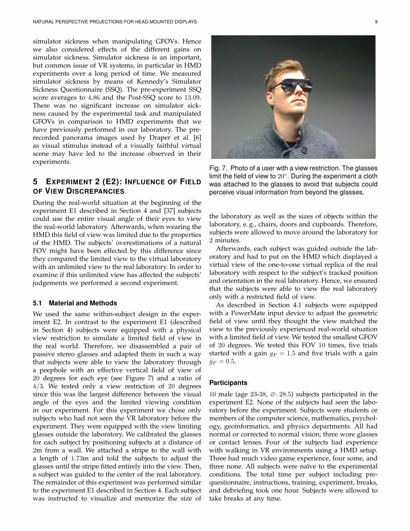
We used the same within-subject design in the exper-iment E2. In contrast to the experiment E1 (describedin Section 4) subjects were equipped with a physicalview restriction to simulate a limited field of view inthe real world. Therefore, we disassembled a pair ofpassive stereo glasses and adapted them in such a waythat subjects were able to view the laboratory througha peephole with an effective vertical field of view of20 degrees for each eye (see Figure 7) and a ratio of4/3. We tested only a view restriction of 20 degreessince this was the largest difference between the visualangle of the eyes and the limited viewing conditionin our experiment. For this experiment we chose onlysubjects who had not seen the VR laboratory before theexperiment. They were equipped with the view limitingglasses outside the laboratory. We calibrated the glassesfor each subject by positioning subjects at a distance of2m from a wall. We attached a stripe to the wall witha length of 1.73m and told the subjects to adjust theglasses until the stripe fitted entirely into the view. Then,a subject was guided to the center of the real laboratory.The remainder of this experiment was performed similarto the experiment E1 described in Section 4. Each subjectwas instructed to visualize and memorize the size of
Fig. 7. Photo of a user with a view restriction. The glasseslimit the field of view to 20◦. During the experiment a clothwas attached to the glasses to avoid that subjects couldperceive visual information from beyond the glasses.
the laboratory as well as the sizes of objects within thelaboratory, e. g., chairs, doors and cupboards. Therefore,subjects were allowed to move around the laboratory for2 minutes.
Afterwards, each subject was guided outside the lab-oratory and had to put on the HMD which displayed avirtual view of the one-to-one virtual replica of the reallaboratory with respect to the subject’s tracked positionand orientation in the real laboratory. Hence, we ensuredthat the subjects were able to view the real laboratoryonly with a restricted field of view.
As described in Section 4.1 subjects were equippedwith a PowerMate input device to adjust the geometricfield of view until they thought the view matched theview to the previously experienced real-world situationwith a limited field of view. We tested the smallest GFOVof 20 degrees. We tested this FOV 10 times, five trialsstarted with a gain gF = 1.5 and five trials with a gaingF = 0.5.
Participants
10 male (age 23-38, ∅: 28.5) subjects participated in theexperiment E2. None of the subjects had seen the labo-ratory before the experiment. Subjects were students ormembers of the computer science, mathematics, psychol-ogy, geoinformatics, and physics departments. All hadnormal or corrected to normal vision; three wore glassesor contact lenses. Four of the subjects had experiencewith walking in VR environments using a HMD setup.Three had much video game experience, four some, andthree none. All subjects were naıve to the experimentalconditions. The total time per subject including pre-questionnaire, instructions, training, experiment, breaks,and debriefing took one hour. Subjects were allowed totake breaks at any time.
NATURAL PERSPECTIVE PROJECTIONS FOR HEAD-MOUNTED DISPLAYS 10
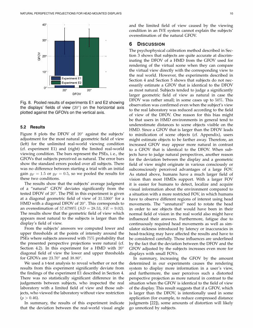
Fig. 8. Pooled results of experiments E1 and E2 showingthe displays’ fields of view (20◦) on the horizontal axisplotted against the GFOVs on the vertical axis.
5.2 Results
Figure 8 plots the DFOV of 20◦ against the subjects’adjustment for the most natural geometric field of view(left) for the unlimited real-world viewing condition(cf. experiment E1) and (right) the limited real-worldviewing condition. The bars represent the PSEs, i. e., theGFOVs that subjects perceived as natural. The error barsshow the standard errors pooled over all subjects. Therewas no difference between starting a trial with an initialgain gF = 1.5 or gF = 0.5, so we pooled the results forthese two conditions.
The results show that the subjects’ average judgmentof a “natural” GFOV deviates significantly from thetested DFOV of 20◦. The PSE in this experiment is givenat a diagonal geometric field of view of 31.5360◦ for aHMD with a diagonal DFOV of 20◦. This corresponds toan overestimation of 57.6799% (SD = 28.53, SE = 9.02).The results show that the geometric field of view whichappears most natural to the subjects is larger than thedisplay’s field of view.
From the subjects’ answers we computed lower andupper thresholds at the points of intensity around thePSEs where subjects answered with 75% probability thatthe presented perspective projections were natural (cf.Section 4.2). In this experiment for a HMD with 20◦
diagonal field of view the lower and upper thresholdsfor GFOVs are 23.70◦ and 38.80◦.
We used a t-test analysis to reveal whether or not theresults from this experiment significantly deviate fromthe findings of the experiment E1 described in Section 4.There was no statistically significant difference in thejudgements between subjects, who inspected the reallaboratory with a limited field of view and those sub-jects, who viewed the laboratory without view restriction(p > 0.46).
In summary, the results of this experiment indicatethat the deviation between the real-world visual angle
and the limited field of view caused by the viewingcondition in an IVE system cannot explain the subjects’overestimation of the natural GFOV.
6 DISCUSSIONThe psychophysical calibration method described in Sec-tion 3 shows that subjects are quite accurate at discrim-inating the DFOV of a HMD from the GFOV used forrendering of the virtual scene when they can comparethe virtual view directly with the corresponding view tothe real world. However, the experiments described inSection 4 and Section 5 shows that subjects do not nec-essarily estimate a GFOV that is identical to the DFOVas most natural. Subjects tended to judge a significantlylarger geometric field of view as natural in case theDFOV was rather small; in some cases up to 50%. Thisobservation was confirmed even when the subject’s viewto the real laboratory was reduced according to the fieldof view of the DFOV. One reason for this bias mightbe that users in HMD environments in general tend tounderestimate distances to scene objects visible on theHMD. Since a GFOV that is larger than the DFOV leadsto minification of scene objects (cf. Appendix), usersmight estimate objects to be farther away. Therefore, anincreased GFOV may appear more natural in contrastto a GFOV that is identical to the DFOV. When sub-jects have to judge natural perspectives, another reasonfor the deviation between the display and a geometricfield of view might originate in various consciously orsubconsciously perceived advantages of a large FOV.As stated above, humans have a much larger field ofvision than most HMDs support. With a larger FOVit is easier for humans to detect, localize and acquirevisual information about the environment compared toa situation with a more restricted FOV, in which humanshave to observe different regions of interest using headmovements. The “unnatural” need to rotate the headin order to see objects that would have been in theirnormal field of vision in the real world also might haveinfluenced their answers. Furthermore, fatigue due tocontinuously required head movements as well as sim-ulator sickness introduced by latency or inaccuracies inhead-tracking may have affected the results and have tobe considered carefully. Those influences are underlinedby the fact that the deviation between the DFOV and theGFOV adjusted by the subjects increases even more fordisplays with small FOVs.
In summary, increasing the GFOV by the amountdetermined in our experiments causes the renderingsystem to display more information in a user’s view,and furthermore, the user perceives such a distortedperspective projection as more natural in contrast to thesituation when the GFOV is identical to the field of viewof the display. This result suggests that if a GFOV, whichis larger than the DFOV, is intentionally used in someapplication (for example, to reduce compressed distancejudgments [22]), some amounts of distortion will likelygo unnoticed by subjects.
NATURAL PERSPECTIVE PROJECTIONS FOR HEAD-MOUNTED DISPLAYS 11
7 CONCLUSION AND FUTURE WORK
In this article we have presented a psychophysical cal-ibration method that allows to determine the DFOV ofa HMD as perceived by users, and we have conductedtwo experiments to identify geometric fields of view thatappear most natural to users in such a HMD environ-ment. We found that the GFOVs users judge as mostnatural are not identical to the FOVs supported by theHMDs; for all tested FOVs subjects reported a largergeometric than display’s FOV as natural. We determinedhow much a GFOV has to deviate from a DFOV inorder for subjects to estimate the virtual perspectiveprojection as natural. We believe that increasing theGFOV to the point where users perceive the perspectiveas most natural–though this may lead to perspectivedistortions that influence the perceived size of objects,distances and optical flow patterns–has the potential toenhance the overall VR experience. Increased GFOVsafford more information into the limited field of viewof a HMD, which leads to more visual information ina user’s view. Furthermore, it has been shown that alarger field of view (resulting in an increased overlapof visual information during camera motions) supportsa user’s ability to form a cognitive map of unknownvirtual worlds [5]. Kuhl et al. [21] further showed thatslightly increased GFOVs and the resulting minificationof the displayed graphics (compared to a view from thereal world) reduces the distance compression effects inVEs. We compared the results of different tested FOVs,and we found that the PSEs between a DFOV and GFOVare shifted towards increased GFOVs for HMDs witha small FOV. The results provide interesting insightsfor the specification of GFOVs in HMD environments.In order to render a VE so that the scene appearsmost natural to users, for HMDs with 20◦ diagonalDFOV the GFOV should be set to 29.53◦ , respectively53.85◦ for HMDs with 40◦ diagonal DFOV, 72.33◦ forHMDs with 60◦ DFOV, and 88.34◦ for HMDs with 76.88◦
DFOV (the largest DFOV we have tested). However, incertain situations the geometric field of view desiredby users may be much larger in order to get a betterimpression of an unknown VE or even smaller, sincein this case the display resolution is increased becauseless pixels are mapped to the same display area. It isa challenging question whether the display’s optimalfield of view for arbitrary environments and situationscan be predetermined. In the future we will pursuethese questions more deeply and explore the effects ofgeometric fields of view, which deviate from displays’FOVs, on spatial perception in VEs. In particular, wewill examine in how far the increased geometric fields ofview, which appear natural to VR users, reduce distancecompression effects, when the virtual world is displayedwith a corresponding perspective projection.
8 ACKNOWLEDGMENTS
The authors of this work are supported by the Ger-man Science Foundation DFG 29160938, DFG 29160962,DFG LA-952/3 and DFG LA-952/4, the German FederalMinistry of Education and Research project Visuo-spatialCognition, and the EC Project Eyeshots.
APPENDIX
The nominal field of view for most HMDs is specifiedby the manufacturers as visual angle α across the diag-onal of the screen with a given aspect ratio in screenspace denoted by ratio. Assuming a symmetrical viewfrustum, the horizontal and vertical fields of view fovxand fovy can then be calculated with equations (3) and(4):
fovx = 2 · atan
tan(α/2)√1 + 1
ratio2
(3)
fovy = 2 · atan
(tan(α/2)√1 + ratio2
)(4)
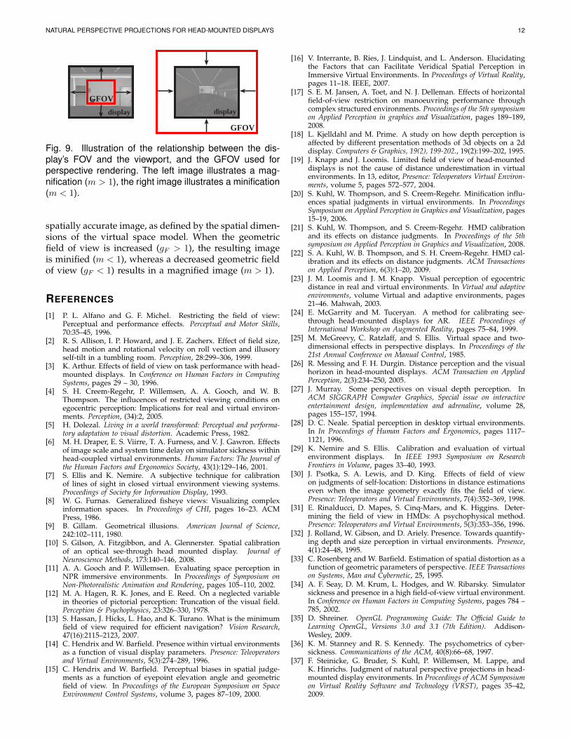
In a computer graphics system usually only the ver-tical geometric field of view (fovy) has to be specifiedfrom which the vertical extent of the near plane iscalculated, and then the horizontal extent of the nearplane is derived using the ratio. Mini- or magnificationof the graphics is caused by changing the size of thenear plane, e. g., by adjusting the vertical and horizontalgeometric field of view (see Figure 9). As stated abovesuch a mini- or magnification changes several visualcues that provide distance information. In particular,minification changes three specific cues in a way that canpotentially increase perceived distances to objects [20]:(1) it reduces the visual angle, (2) familiar size cues maymake objects appear more distant, and (3) minificationcauses binocular convergence to indicate that objects aremore distant. On the other hand, magnification changesthese cues in an opposite direction and can potentiallydecrease perceived distance.
The described mini- and magnification can be imple-mented as follows. Let fovy denote the vertical geometricfield of view before mini- or magnification. We assumethat the horizontal geometric field of view fovx is definedaccording to the ratio. If fovy is scaled by a gain gF (andfovx is modified accordingly using ratio), we can deter-mine the amount m of mini- respectively magnificationwith the following equation:
m =tan(fovy/2)
tan((gF · fovy)/2)(5)
As illustrated in Figure 9, the mini-/magnification mdenotes the amount of uniform scaling that is requiredto map the viewport (rendered with a certain GFOV)to the display (defined by its DFOV and ratio). If thismini-/magnification equals 1.0, a person will perceive a
NATURAL PERSPECTIVE PROJECTIONS FOR HEAD-MOUNTED DISPLAYS 12
GFOV
GFOVdisplaydisplay
Fig. 9. Illustration of the relationship between the dis-play’s FOV and the viewport, and the GFOV used forperspective rendering. The left image illustrates a mag-nification (m > 1), the right image illustrates a minification(m < 1).
spatially accurate image, as defined by the spatial dimen-sions of the virtual space model. When the geometricfield of view is increased (gF > 1), the resulting imageis minified (m < 1), whereas a decreased geometric fieldof view (gF < 1) results in a magnified image (m > 1).
REFERENCES
[1] P. L. Alfano and G. F. Michel. Restricting the field of view:Perceptual and performance effects. Perceptual and Motor Skills,70:35–45, 1996.
[2] R. S. Allison, I. P. Howard, and J. E. Zacherx. Effect of field size,head motion and rotational velocity on roll vection and illusoryself-tilt in a tumbling room. Perception, 28:299–306, 1999.
[3] K. Arthur. Effects of field of view on task performance with head-mounted displays. In Conference on Human Factors in ComputingSystems, pages 29 – 30, 1996.
[4] S. H. Creem-Regehr, P. Willemsen, A. A. Gooch, and W. B.Thompson. The influcences of restricted viewing conditions onegocentric perception: Implications for real and virtual environ-ments. Perception, (34):2, 2005.
[5] H. Dolezal. Living in a world transformed: Perceptual and performa-tory adaptation to visual distortion. Academic Press, 1982.
[6] M. H. Draper, E. S. Viirre, T. A. Furness, and V. J. Gawron. Effectsof image scale and system time delay on simulator sickness withinhead-coupled virtual environments. Human Factors: The Journal ofthe Human Factors and Ergonomics Society, 43(1):129–146, 2001.
[7] S. Ellis and K. Nemire. A subjective technique for calibrationof lines of sight in closed virtual environment viewing systems.Proceedings of Society for Information Display, 1993.
[8] W. G. Furnas. Generalized fisheye views: Visualizing complexinformation spaces. In Proceedings of CHI, pages 16–23. ACMPress, 1986.
[9] B. Gillam. Geometrical illusions. American Journal of Science,242:102–111, 1980.
[10] S. Gilson, A. Fitzgibbon, and A. Glennerster. Spatial calibrationof an optical see-through head mounted display. Journal ofNeuroscience Methods, 173:140–146, 2008.
[11] A. A. Gooch and P. Willemsen. Evaluating space perception inNPR immersive environments. In Proceedings of Symposium onNon-Photorealistic Animation and Rendering, pages 105–110, 2002.
[12] M. A. Hagen, R. K. Jones, and E. Reed. On a neglected variablein theories of pictorial perception: Truncation of the visual field.Perception & Psychophysics, 23:326–330, 1978.
[13] S. Hassan, J. Hicks, L. Hao, and K. Turano. What is the minimumfield of view required for efficient navigation? Vision Research,47(16):2115–2123, 2007.
[14] C. Hendrix and W. Barfield. Presence within virtual environmentsas a function of visual display parameters. Presence: Teleoperatorsand Virtual Environments, 5(3):274–289, 1996.
[15] C. Hendrix and W. Barfield. Perceptual biases in spatial judge-ments as a function of eyepoint elevation angle and geometricfield of view. In Proceedings of the European Symposium on SpaceEnvironment Control Systems, volume 3, pages 87–109, 2000.
[16] V. Interrante, B. Ries, J. Lindquist, and L. Anderson. Elucidatingthe Factors that can Facilitate Veridical Spatial Perception inImmersive Virtual Environments. In Proceedings of Virtual Reality,pages 11–18. IEEE, 2007.
[17] S. E. M. Jansen, A. Toet, and N. J. Delleman. Effects of horizontalfield-of-view restriction on manoeuvring performance throughcomplex structured environments. Proceedings of the 5th symposiumon Applied Perception in graphics and Visualization, pages 189–189,2008.
[18] L. Kjelldahl and M. Prime. A study on how depth perception isaffected by different presentation methods of 3d objects on a 2ddisplay. Computers & Graphics, 19(2), 199-202., 19(2):199–202, 1995.
[19] J. Knapp and J. Loomis. Limited field of view of head-mounteddisplays is not the cause of distance underestimation in virtualenvironments. In 13, editor, Presence: Teleoperators Virtual Environ-ments, volume 5, pages 572–577, 2004.
[20] S. Kuhl, W. Thompson, and S. Creem-Regehr. Minification influ-ences spatial judgments in virtual environments. In ProceedingsSymposium on Applied Perception in Graphics and Visualization, pages15–19, 2006.
[21] S. Kuhl, W. Thompson, and S. Creem-Regehr. HMD calibrationand its effects on distance judgments. In Proceedings of the 5thsymposium on Applied Perception in Graphics and Visualization, 2008.
[22] S. A. Kuhl, W. B. Thompson, and S. H. Creem-Regehr. HMD cal-ibration and its effects on distance judgments. ACM Transactionson Applied Perception, 6(3):1–20, 2009.
[23] J. M. Loomis and J. M. Knapp. Visual perception of egocentricdistance in real and virtual environments. In Virtual and adaptiveenvironments, volume Virtual and adaptive environments, pages21–46. Mahwah, 2003.
[24] E. McGarrity and M. Tuceryan. A method for calibrating see-through head-mounted displays for AR. IEEE Proceedings ofInternational Workshop on Augmented Reality, pages 75–84, 1999.
[25] M. McGreevy, C. Ratzlaff, and S. Ellis. Virtual space and two-dimensional effects in perspective displays. In Proceedings of the21st Annual Conference on Manual Control, 1985.
[26] R. Messing and F. H. Durgin. Distance perception and the visualhorizon in head-mounted displays. ACM Transaction on AppliedPerception, 2(3):234–250, 2005.
[27] J. Murray. Some perspectives on visual depth perception. InACM SIGGRAPH Computer Graphics, Special issue on interactiveentertainment design, implementation and adrenaline, volume 28,pages 155–157, 1994.
[28] D. C. Neale. Spatial perception in desktop virtual environments.In In Proceedings of Human Factors and Ergonomics, pages 1117–1121, 1996.
[29] K. Nemire and S. Ellis. Calibration and evaluation of virtualenvironment displays. In IEEE 1993 Symposium on ResearchFrontiers in Volume, pages 33–40, 1993.
[30] J. Psotka, S. A. Lewis, and D. King. Effects of field of viewon judgments of self-location: Distortions in distance estimationseven when the image geometry exactly fits the field of view.Presence: Teleoperators and Virtual Environments, 7(4):352–369, 1998.
[31] E. Rinalducci, D. Mapes, S. Cinq-Mars, and K. Higgins. Deter-mining the field of view in HMDs: A psychophysical method.Presence: Teleoperators and Virtual Environments, 5(3):353–356, 1996.
[32] J. Rolland, W. Gibson, and D. Ariely. Presence. Towards quantify-ing depth and size perception in virtual environments. Presence,4(1):24–48, 1995.
[33] C. Rosenberg and W. Barfield. Estimation of spatial distortion as afunction of geometric parameters of perspective. IEEE Transactionson Systems, Man and Cybernetic, 25, 1995.
[34] A. F. Seay, D. M. Krum, L. Hodges, and W. Ribarsky. Simulatorsickness and presence in a high field-of-view virtual environment.In Conference on Human Factors in Computing Systems, pages 784 –785, 2002.
[35] D. Shreiner. OpenGL Programming Guide: The Official Guide toLearning OpenGL, Versions 3.0 and 3.1 (7th Edition). Addison-Wesley, 2009.
[36] K. M. Stanney and R. S. Kennedy. The psychometrics of cyber-sickness. Communications of the ACM, 40(8):66–68, 1997.
[37] F. Steinicke, G. Bruder, S. Kuhl, P. Willemsen, M. Lappe, andK. Hinrichs. Judgment of natural perspective projections in head-mounted display environments. In Proceedings of ACM Symposiumon Virtual Reality Software and Technology (VRST), pages 35–42,2009.
NATURAL PERSPECTIVE PROJECTIONS FOR HEAD-MOUNTED DISPLAYS 13
[38] W. B. Thompson, P. Willemsen, A. A. Gooch, S. H. Creem-Regehr,J. M. Loomis, and A. C. Beall. Does the quality of the computergraphics matter when judging distances in visually immersiveenvironments? Presence: Teleoperators and Virtual Environments,13(5):560–571, 2004.
[39] M. Usoh, E. Catena, S. Arman, and M. Slater. Using presencequestionaires in reality. Presence: Teleoperator in Virtual Environ-ments, 9(5):497–503, 1999.
[40] R. Warren and A. H. Wertheim. Perception & Control of Self-Motion.Lawrence Erlbaum Associates, 1990.
[41] P. Willemsen, M. B. Colton, S. Creem-Regehr, and W. B. Thomp-son. The effects of head-mounted display mechanical propertiesand field-of-view on distance judgments in virtual environments.ACM Transactions on Applied Perception, 2(6), 2009.
[42] P. Willemsen and A. A. Gooch. Perceived egocentric distancesin real, image-based, and traditional virtual environments. InProceedings of the IEEE Virtual Reality, pages 275–276, 2002.
[43] B. G. Witmer and P. B. Kline. Judging perceived and traverseddistance in virtual environments. Presence: Teleoperators and VirtualEnvironments, 7(2):144–167, 1998.
[44] B. G. Witmer and J. W. Sadowski. Nonvisually guided locomotionto a previously viewed target in real and virtual environments.Human Factors, 40(i3):489–484, 1998.
[45] U. Yang and G. J. Kim. Increasing the effective egocentric fieldof view with proprioceptive and tactile feedback. In Proceedingsof the IEEE Virtual Reality, pages 27–34, 2004.
Frank Steinicke received the diploma in math-ematics with a minor in computer science in2002, and the Ph.D. degree in 2006 in computerscience from the University of Munster, Ger-many. He is currently a research associate in theVisualization and Computer Graphics (VisCG)research group at the University of Munster. Hisresearch interests include computer graphicsand human-computer interaction with focus onvirtual reality, as well as perception and cognitionin computer-generated environments.
Gerd Bruder received the diploma degree incomputer science from the University of Munsterin 2009. Currently, he is a Ph.D. student inthe VisCG research group at the University ofMunster and works in the LOCUI project fundedby the German Research Foundation. His re-search interests include computer graphics, VR-based locomotion techniques, human-computerinteraction and perception in immersive virtualenvironments.
Scott Kuhl received his Ph.D. in computer sci-ence from University of Utah’s School of Com-puting in 2009. He also has bachelor degrees incomputer science and mathematics from Augs-burg College in Minneapolis, Minnesota. He iscurrently an assistant professor of ComputerScience at Michigan Technological University.His research interests include space perception,immersive virtual environments, and computergraphics.
Pete Willemsen earned his Ph.D. in computerscience from the University of Iowa in 2000.He continued as a post-doctoral researcher andresearch assistant professor in the School ofComputing at the University of Utah. Currently,he is an associate professor of computer sci-ence at the University of Minnesota Duluth. Hisresearch interests are in human-computer inter-action with an emphasis on virtual environments,applied perception in graphics and visualization,and real-time virtual environment simulation.
Markus Lappe holds a Ph.D. in physics fromthe University of Tubingen, Germany. He didresearch work on computational and cognitiveneuroscience of vision at the MPI of BiologicalCybernetics in Tubingen, the National Institutesof Health, Bethesda, USA, and the Departmentof Biology of the Ruhr-University Bochum, Ger-many. Since 2001 he is a full professor of ex-perimental psychology, and member of the OttoCreutzfeldt Center for Cognitive and BehavioralNeuroscience at the University of Munster.
Klaus Hinrichs received the diploma in math-ematics with a minor in computer science fromthe University of Hannover, Germany, and thePhD degree in 1985 from the Swiss FederalInstitute of Technology (ETH) in Zurich. He is afull professor of computer science at the Univer-sity of Munster, Germany. His research interestsinclude visualization, computer graphics, algo-rithms and data structures for geometric compu-tation, and spatial data bases.