nato/ccms pilot study evaluation of demonstrated and ... · pdf filegérard evers...
TRANSCRIPT

COMMITTEE ON EPA 542-R-98-003THE CHALLENGES OF May 1998MODERN SOCIETY www.clu-in.com
www.nato/ccms
NATO/CCMS Pilot Study
Evaluation of Demonstrated andEmerging Technologies for the
Treatment of Contaminated Landand Groundwater (Phase III)
1998SPECIAL SESSION
Treatment Walls andPermeable Reactive Barriers
Number 229
NORTH ATLANTIC TREATY ORGANIZATION

NATO/CCMS Pilot Study
Evaluation of Demonstrated andEmerging Technologies for
the Treatment of ContaminatedLand and Groundwater — Phase III
SPECIAL SESSION ON
Treatment Walls andRermeable Reactive Barriers
Harald Burmeier, Chairman
University of ViennaVienna, Austria
FEBRUARY 22 - 28, 1998
May 1998

NOTICEThis report was prepared under the auspices of the North Atlantic Treaty Organization’s Committee on theChallenges of Modern Society (NATO/CCMS) as a service to the technical community by the United StatesEnvironmental Protection Agency (U.S. EPA). The document was funded by U.S. EPA’s TechnologyInnovation Office under the direction of Dr. Michael Kosakowski. The Annual Report was edited andproduced by Environmental Management Support, Inc., of Silver Spring, Maryland, under U.S. EPAcontract 68-W6-0014. Mention of trade names or specific applications does not imply endorsement oracceptance by U.S. EPA.

Treatment Walls NATO/CCMS Pilot Study Phase III
i
CONTENTS
Introduction . . . . . . . . . . . . . . . . . . . . . . . . . . . . . . . . . . . . . . . . . . . . . . . . . . . . . . . . . . . . . . . . . . . . . . iii
General Overview. . . . . . . . . . . . . . . . . . . . . . . . . . . . . . . . . . . . . . . . . . . . . . . . . . . . . . . . . . . . . . . . . . 1Harald Burmeier
Permeable Reactive Barrier Research at the National Risk Management Research Laboratory,U.S. Environmental Protection Agency. . . . . . . . . . . . . . . . . . . . . . . . . . . . . . . . . . . . . . . . . . . 3
Robert W. Puls
Technical Construction of Treatment Walls
Permeable Treatment Walls—Design, Construction, and Cost. . . . . . . . . . . . . . . . . . . . . . . . . . . . . . . . 6Eberhard Beitinger
Development of Iron-Based Reactive Barrier Technologies for Remediation of Chlorinated OrganicContaminants in Groundwater. . . . . . . . . . . . . . . . . . . . . . . . . . . . . . . . . . . . . . . . . . . . . . . . . . 17
Robert W. Gillham
Practical Solutions for the Treatment of Polluted Groundwater. . . . . . . . . . . . . . . . . . . . . . . . . . . . . . 22Gérard Evers
Reactive Materials
Degradation of TCE at Zero-Valent Iron: Chemical Processes Effecting the Design and Performanceof Permeable, Reactive Fe(0) Walls. . . . . . . . . . . . . . . . . . . . . . . . . . . . . . . . . . . . . . . . . . . . . 30
Wolfgang Wüst, O. Schlicker, and A. Dahmke
The Treatment of Groundwater with Mixed-Wastes: Reductive Dechlorination of TCE and Reductive Precipitation of Uranium. . . . . . . . . . . . . . . . . . . . . . . . . . . . . . . . . . . . . . 36
Liyuan Liang and B. Gu
Bioprocesses in Treatment Walls: Bioscreens. . . . . . . . . . . . . . . . . . . . . . . . . . . . . . . . . . . . . . . . . . . . 44Huub H. M. Rijnaarts
Novel Catalyses for Reactive Barriers. . . . . . . . . . . . . . . . . . . . . . . . . . . . . . . . . . . . . . . . . . . . . . . . . . 48Timothy M. Vogel
Full-Scale Projects
Funnel-and-Gate Systems for In Situ Treatment of Contaminated Groundwater at Former Manufactured Gas Plant Sites. . . . . . . . . . . . . . . . . . . . . . . . . . . . . . . . . . . . . . . . . . . . 56
Hermann Schad and Peter Grathwohl
Reactive Treatment Zones: Concepts and a Case History. . . . . . . . . . . . . . . . . . . . . . . . . . . . . . . . . . . 66Stephan A. Jefferis and Graham H. Norris

Treatment Walls NATO/CCMS Pilot Study Phase III
ii
Horizontal Treatment Barriers of Fracture-Emplaced Iron and Permanganate Particles. . . . . . . . . . . . 77Robert L. Siegrist, Kathryn S. Lowe, Lawrence W. Murdoch,
Traci L. Case, Douglas A. Pickering, and Thomas C. Houk
In Situ Remediation Research in a Complexly Contaminated Aquifer: The SAFIRA Test Site at Bitterfeld, Germany. . . . . . . . . . . . . . . . . . . . . . . . . . . . . . . . . . . . . . . . . . . . . . . . . . . . . . . . 84
H. Weiss, F.-D. Kopinke, P. Popp, and L. Wünsche
Summary and Conclusions. . . . . . . . . . . . . . . . . . . . . . . . . . . . . . . . . . . . . . . . . . . . . . . . . . . . . . . . . . . 92Harald Burmeier
ABOUT THE AUTHORS . . . . . . . . . . . . . . . . . . . . . . . . . . . . . . . . . . . . . . . . . . . . . . . . . . . . . . . . . . . 95
NATIONAL CONTACTS . . . . . . . . . . . . . . . . . . . . . . . . . . . . . . . . . . . . . . . . . . . . . . . . . . . . . . . . . . . 98
PARTICIPANTS . . . . . . . . . . . . . . . . . . . . . . . . . . . . . . . . . . . . . . . . . . . . . . . . . . . . . . . . . . . . . . . . . 102

Treatment Walls NATO/CCMS Pilot Study Phase III
iii
Introduction
The Council of the North Atlantic Treaty Organization (NATO) established the Committee on theChallenges of Modern Society (CCMS) in 1969. CCMS was charged with developing meaningful programsto share information among countries on environmental and societal issues that complement otherinternational endeavors and to provide leadership in solving specific problems of the human environment.A fundamental precept of CCMS involves the transfer of technological and scientific solutions amongnations with similar environmental challenges.
The management of contaminated land and groundwater is a universal problem among industrializedcountries, requiring the use of existing, emerging, innovative, and cost-effective technologies. Thisdocument provides a report from the first meeting of the Phase III Pilot Study and is designed to shareinformation among countries on innovative treatment technologies. The United States is the lead countryfor the Pilot Study, and Germany and The Netherlands are the Co-Pilot countries. The first phasesuccessfully concluded in 1991, and the results were published in three volumes. The second phase, whichexpanded to include newly emerging technologies, concluded in 1997; final reports documenting 52completed projects and the participation of 14 countries will be published in 1998. Through these pilotstudies, critical technical information has been made available to participating countries and the worldcommunity.
Phase III focuses on the technical approaches for addressing the treatment of contaminated land andgroundwater. This includes issues of sustainability, environmental merit, and cost-effectiveness in additionto continuing to draw on the merits of emerging remediation technologies. The objectives of the study areto critically evaluate technologies, promote the appropriate use of technologies, use information technologysystems to disseminate the products, and to foster innovative thinking in the area of contaminated land. Thefirst meeting of the Phase III Pilot Study on the Evaluation of Demonstrated and Emerging Technologiesfor the Treatment and Clean Up of Contaminated Land and Groundwater convened in Vienna, Austria, onFebruary 22-27, 1998, with representatives of 20 countries attending. Each participating country presentscase studies or projects to the Pilot Study for discussion.
Also at this first Phase III meeting, the first special technical session was convened on treatment walls andrelated permeable reactive barrier technologies, under the chairmanship of Prof. Dipl.-Ing. Harald Burmeierof the University of Northeast Lower Saxony. This report contains the proceedings of that special session.A companion publication, the first Annual Report of the Phase III studies, contains abstracts of the first 15demonstration projects selected, reports on the legislative, regulatory, programmatic, and research issuesrelated to contaminated land in each participating country, and the statement of purpose for the Phase IIIPilot Study. General information on the NATO/CCMS Pilot Study may be obtained from the CountryRepresentatives listed at the end of this report, or—for each paper—from the authors themselves.
Stephen C. JamesWalter W. Kovalick, Jr., Ph.D.Co-Directors

Treatment Walls NATO/CCMS Pilot Study Phase III
University of Applied Studies and Research, University of Northeast Lower Saxony, Herbert-Meyerstrasse 7, 295561
Suderburg, Germany, tel: 49/5103-2000, fax: 49/5103-7863, e-mail: [email protected]
1
General Overview
Harald Burmeier1
Remediation of groundwater is most commonly performed by “pump-and-treat” methods: the contaminatedgroundwater is extracted from the aquifer and subjected to above-ground-treatment before being reinjectedor discharged. Multi-component systems are designed according to the particular contamination by takingphysical, chemical, and biological treatment processes into consideration.
Pump-and-treat methods require continuous energy for pumping water from the extraction wells andoperating the water treatment systems. Besides that, periodic maintenance and monitoring has to beperformed. Generally, these systems have to be operated for a long time. As a consequence, remediationcosts are substantial. Despite the wide spectrum of technologies available for above-ground treatment,residual contaminants frequently remain at undesirably high levels in the subsurface.
Alternatives to these methods are passive working systems that depend on the usage of the groundwater’snatural hydraulics. There is a wide spectrum of possible solutions ranging from intrinsic remediation topermeable reactive or adsorptive barriers.
As early as 1982, the idea to treat contaminated groundwater by installing a permeable reactive barrier wasshown in a figure in a remediation handbook issued by the U.S. EPA. But the 1980s were not the time forfurther development of such innovative in-situ clean-up methods.
In 1989, the potential of Permeable Reactive Barriers (PRB) was recognized more clearly and was developedfurther by the University of Waterloo, Canada. Since that time a lot of laboratory- and bench-scale investi-gations led to the first full-scale in situ demonstration at Borden, Ontario, Canada.
Now, in 1998, over 500 project studies world-wide reflect the interest in this technology. The small numberof so far only 20 commercial applications shows that it is a long way from the pilot study to the fieldapplication.
Today, a lot of experts in North America and Europe are working on several research issues concerning thePRB technology, as there are:
• processes in the media and aquifers (hydraulics, geochemistry, etc.), • suitable materials for reactive walls, • design and construction, • long-term effectiveness, • treatment of contaminant-mixtures, and • standards for construction, monitoring, etc.
Although many questions remain to be answered, a significant cost reduction potential of more than 30percent is expected when PRBs are used instead of pump-and-treat methods.
In this Special Session of the Phase III Pilot Study on the Evaluation of Demonstrated and Emerging Tech-nologies for the Treatment and Clean Up of Contaminated Land and Groundwater (Phase III), a dozen

Treatment Walls NATO/CCMS Pilot Study Phase III
2
papers are presented on the international state-of-the-art concerning technical construction issues, reactormaterials, and full-scale projects. This report summarizes those proceedings and the discussions followingthem, research and development needs, and recommendations for further action items.
I would like to extend my special thanks to all experts for preparing reports and giving presentations duringthis Pilot Study Meeting in Vienna. Last-but-not-least, I would like to gratefully acknowledge the input andsubstantial support provided by Steve James, John Moerlins, and Volker Franzius during the preparationand coordination of this session.
Treatment Walls NATO/CCMS Pilot Study Phase III
U.S. Environmental Protection Agency, R.S. Kerr Environmental Center, P.O. Box 1198, Ada, OK 74821-1198, USA,1
e-mail: [email protected]
3
Permeable Reactive Barrier Research at theNational Risk Management Research Laboratory,
U.S. Environmental Protection Agency
Robert W. Puls1
Much of the current research on ground-water remediation has focused on the removal of contaminatedwater from the subsurface and treating it at the surface. While the removal of the contaminants is desirable,the costs are often prohibitive and rarely are contaminant concentrations lowered to the required regulatorylevels. This has been particularly evident for standard “pump-and-treat” approaches. In situ chemicallyreactive permeable walls are being considered as a low-cost and effective alternative for the treatment ofcontaminated waste sites. The chemical form of the contaminant in question is transformed via oxidation,reduction or precipitation reactions to an immobilized or non-toxic form. The application of in situapproaches to subsurface remediation will increase the emphasis on adequate site characterization andthorough understanding of the subsurface system targeted for remediation as well as the geochemicalmechanisms controlling contaminant transformations.
Background
Research into the use of zero-valent metals to remediate ground-water contaminated with mixed wastes(inorganic and organic) has been ongoing at the U.S. Environmental Protection Agency’s National RiskManagement Research Laboratory (NRMRL) in Ada, Oklahoma since 1991. The primary emphasis has beenon inorganic constituents such as chromate, arsenic, nitrate and sulfate and chlorinated organic compounds(e.g., trichloroethylene, cis-dichloroethylene, and vinyl chloride). Laboratory research conducted byscientists at the NRMRL conclusively demonstrated the effectiveness of using zero-valent metals toremediate chromate and chlorinated organic compounds in groundwater and this research was scaled up toa pilot-scale demonstration in September 1994, near an old chrome plating facility on the U.S. Coast Guard(USCG) Support Center near Elizabeth City, North Carolina. Results indicated that complete treatment ofchromium and the chlorinated organic compounds in the groundwater was possible using this technology.Chromium concentrations were reduced to less than 0.01 mg/l, much less than drinking water limits. Thechromate was reduced via corrosion of the elemental iron to the nontoxic and insoluble chromic ion (Cr),3+
which forms an insoluble mixed chromium-iron hydroxide phase. The chlorinated organic compounds weresimilarly degraded to below maximum contaminant levels set for groundwater by the U.S. EPA.
Full-Scale Systems
A full-scale demonstration of a permeable reactive barrier to remediate groundwater contaminated withchromate and chlorinated organic compounds was initiated at the USCG site by researchers from NRMRLand the University of Waterloo in 1995. A continuous wall composed of 100% zero-valent iron was installedin June, 1996, using a trencher that was capable of installing the granular iron to a depth of 8 m. Thetrenched wall was approximately 0.6 m thick and about 60 m long. The wall begins about 3 feet below theground surface and consists of about 450 tons of granular iron. The installation of the wall was completedin less than a day. The total installation cost was $500,000, with the cost of iron representing approximately35% of the total. Total installation, site investigation, design feasibility tests, general contracting, and post-installation monitoring costs have been less than $1 million. Savings compared to traditional pump-and-treat

Treatment Walls NATO/CCMS Pilot Study Phase III
4
exceed $5 million over a 10-year period primarily due to reduced operation and maintenance costs due tothe passive nature of this technology.
The continuous trenching equipment used for the installation was similar to a large “Ditch Witch.” It usesa large cutting chain excavator system combined with a trench box and loading hopper. As the trenchingmachine moved along, the cutting chain excavation removed the native soil, while a front end loader filledthe hopper of the trench box. The granular iron flowed through the hopper and out the back of the trenchbox into the just-excavated trench. The walls of the trench box extended to the width and depth of the trenchmaintaining the opening until the iron was emplaced.
The system was designed to meet lower concentrations of contaminants below maximum concentrationlimits (MCLs) for groundwater set by U.S. EPA of 0.05 mg/l Cr(VI), 5 µg/l TCE, 70 µg/l DCE and 2 µg/lVC.
Results
To-date, there has been two years of post-installation performance monitoring performed by these sameresearchers. For all but one quarterly sampling event, 15 multilevel samplers (7 to 11 sample ports persampler) and 9 to 10 compliance (5-cm PVC) wells have been sampled. In addition to on-site sampling ofthe full suite of geochemical indicator parameters listed in the site work plan, samples have been collectedfor laboratory analysis of the following constituents: TCE, cis-DCE, vinyl chloride, ethane, ethene, methane,major anions, and metals. In addition, numerous vertical and angle cores have been collected to examinechanges to the iron surface over time and to evaluate the formation of secondary precipitates which mayaffect wall performance over time. Coring was done vertically (perpendicular to ground surface) and on anangle (30E). The former method provided continuous vertical iron cores, while the latter provided atransverse core through the wall with the aquifer-iron interfaces intact (front and back of the wall). Thesecores continue to be under study. Inorganic carbon contents increase dramatically at the up-gradient aquifersediment-iron interface and decrease within the wall moving down gradient, reaching background levelswithin 10 cm down gradient from the down gradient iron-aquifer sediment interface. Total inorganic carboncontent has increased over time within the wall.
Results of geochemical sampling on site indicate that iron corrosion is proceeding within the wall. Thereare significant reductions in Eh (to >-400 mv), increase in pH (to >10), absence of DO, and decrease inalkalinity. Down gradient of the wall (1.5 m), pH returns to near neutral and Eh is quite variable with depth.Over time there have been indications that a redox front is slowly migrating down gradient within the firstfew meters of the wall. Water levels indicate little difference (<0.1 m) between wells completed andscreened at similar depths up gradient and down gradient of the wall, indicating that the wall continues toeffectively function as a “permeable” reactive barrier.
Sampling results for chromate indicate that all chromate was removed from the groundwater within the first15 cm of the wall as expected. No chromate is detected down gradient of the wall either in the multilayersamplers or in the 5-cm compliance wells located immediately behind the wall.
The vast majority of the multi-layer sampling ports show reduction of the chlorinated compoundconcentrations to less than regulatory target levels. Only one port (ML25-1) continues to show levels abovetarget concentrations. This is the deepest port in the middle of the wall where the organic solvent compoundconcentrations are highest.

Treatment Walls NATO/CCMS Pilot Study Phase III
5
Other Inorganic Contaminants
Other inorganic contaminants currently under study include nitrate and arsenic. These inorganiccontaminants are transformed via oxidation-reduction reactions to less mobile and/or less toxic forms andimmobilized as insoluble precipitates or through essentially irreversible adsorption reactions. Zero-valentiron can effectively transform nitrate to reduced forms as confirmed with mass balance determinations. Theuse of different organic materials also further reduces the nitrate and experiments are in progress to accountfor all nitrogen forms produced. Experiments have also explored the use of iron-organic material mixtures.Experiments with arsenic are currently underway and we are exploring conversion to reduced and oxidizedforms for immobilization in a reactive barrier.
Disclaimer
Although the research described in this article has been funded wholly or in part by the United StatesEnvironmental Protection Agency, it has not been subjected to the Agency’s peer and administrative reviewand therefore may not necessarily reflect the views of the Agency and no official endorsement may beinferred.
Discussion
Zero-valent iron walls can affect the pH of chlorinated solvent plumes. The pH of a plume can increase to10 to 11 after passing through a 100% iron wall. This change is always observed due to the nature of thecorrosion reaction that takes place and occurs regardless of whether the plume contains chlorinated solventsor chromium. However, the iron can be mixed with pyrite or native aquifer sediments (e.g., 50% iron and50% sediment) to buffer the pH in the walls to less than 7.5. The buffered walls exhibit an environmentfavorable for microbial activity, so there is a lot of sulfide is produced. Additionally, hydrogen is producedduring the corrosion reaction at the iron surface. The production of hydrogen is significant—up to 1,000 nMof dissolved hydrogen has been measured at the Elizabeth City site.
Puls’s data documented a buildup of chromium (2% by weight after one year) in the PRB installed atElizabeth City, and Puls expects it to increase in the future. This expectation is based on two-year columntests in which over 3,000 pore volumes were pumped through under accelerated conditions. Although abuildup occurred that reduced the permeability of the column, it did not impact the reduction of chromatein the groundwater. The pressure buildup caused by the precipitate occurred after pumping approximately500 pore volumes. It is difficult to extrapolate these laboratory results to field-scale tests, and Puls said thatthey will continue to monitor for long-term reactivity in the wall.
The residence time for pore water in the fastest part of the barrier is two days. The hydraulic conductivityof the aquifer varies over its 24-foot thickness, and the highest hydraulic conductivity occurs within a 2-meter interval. This interval contains the highest concentrations of Cr, but most of the TCE is found in6+
deeper zones. The reduction of chromium causes no inhibitory or competitive effect on the degradation ofTCE, because the chromium and TCE are present in different intervals. While the hydraulic conductivityof the aquifer ranges from 2-5 inches/day, the hydraulic conductivity of the wall is 10-12 inches/day.

Treatment Walls NATO/CCMS Pilot Study Phase III
WCI Umwelttechnik GmbH, Sophie Charlotten - Str.33, 14059 Berlin, Germany, tel: 49/30-3260-9481, fax: 49/30-1
321-9472
6
Technical Construction of Treatment WallsPermeable Treatment Walls—Design, Construction, and Cost
Eberhard Beitinger1
Abstract
The Design of Permeable Reactive Barriers (PRB) is discussed with reference to preventing effects such asinflow of fine soil particles, precipitation of carbonates, iron and manganese, and loss of effectiveness byuncontrolled growth of biomass.
Several construction methods are presented and evaluated in terms of design objectives, installationmethods, implementation, effectiveness and cost.
1. In Situ Groundwater Remediation with Permeable Reactive Barriers
According to EPA, “...a permeable reactive barrier (PRB) is a passive in situ treatment zone of reactivematerial that degrades or immobilizes contaminants as groundwater flows through it. Natural gradientstransport contaminants through strategically placed treatment media. The media degrade, sorb, precipitate,or remove dissolved organics, metals, radionuclides, and other pollutants. These barriers may containreactants for degrading volatile organics, chelators for immobilizing metals, nutrients and oxygen formicroorganisms to enhance bioremediation, or other agents.” [1]
The following report is focused on construction methods that prevent negative effects that may reduce theeffectiveness of the treatment media, negatively change the hydraulic conditions, or reduce the long-termPRB performance. This includes the application of knowledge and experience from groundwater well designand the evaluation of innovative technologies to remove and/or reactivate the treatment media in situ.
Permeable Reactive Barriers have commonly been, or are designed to be, installed through excavation andreplacement. This method is limited to approximately 8 m in depth, and the costs becomes prohibitive atgreater depths. Alternative installation methods for greater depths include slurry wall construction, highpressure jetting, deep soil mixing, and hydro fracturing in the United States [2]. In Germany large diametervertical borings, slurry methods and a modified deep wall construction are under evaluation or investigation,but have not yet been tested in the field.
2. Design Objectives for Permeable Treatment Walls
The hydraulic behaviors of the two major permeable treatment wall design types—funnel and gate systemsor continuous reactive walls—are based on the hydraulic permeability of the whole construction system,including permeability of filter layers, screens and the treatment media itself. The system permeability ofthe wall construction should be at least twice the permeability of the aquifer. It might be better to choosea factor of 10 times higher permeability for the wall system because of to all the limiting parameters that willreduce permeability with time. The major limiting factors are expected to be as follows:
• inflow and settling of fine-grained soil particles, which will block the pore spaces and reduce thepermeability;

Treatment Walls NATO/CCMS Pilot Study Phase III
7
• precipitation of carbonates such as calcium or magnesium carbonates, iron oxides/hydroxides, andferrous carbonate or other metal precipitates in the filter layer or treatment media;
• uncontrolled growth of microorganism, such as bio-clogging; and • other, mainly long-term and unknown effects, which may reduce the permeability.
The following design objectives are focused mainly on the use of activated carbon as the treatment media.But most of these design objectives may also be useful if zero-valent iron (ZVI) or other media are chosenas reactive filling materials.
Major design objectives are to:
• Prevent the inflow of fine-grained soil particles by installing a filter layer between the adjacent soil andthe treatment media according to the well-known filter criteria;
• Prevent changes to the physical and chemical properties of the groundwater such as temperature,pressure, pH, oxygen content (redox potential), nutrients, or be aware that these changes will result inprecipitation or microorganism activity that might be of advantage in specific cases;
• Design a wall-system that allows the removal and replacement of the treatment media after a period ofseveral years or decades;
• Design a pipe-system in the wall to allow the injection of water or air for flushing to eliminateprecipitates or sludges or to remix the media by turbulence; and
• Design openings for inspection, removal or sampling of the treatment media.
The above list of design objectives may not be applicable in every case. Based on the specific siteconditions, the nature of contamination and the remediation goals, additional design objectives have to beconsidered.
3. Design Criteria
The design of Permeable Reactive Barriers needs to carefully address the following design criteria. Ingeneral, investigations to obtain design data should be planned with reference to the specific designparameters for a long-term performance of the underground treatment wall.Design criteria are:
• Geology • Hydrology • Depth to groundwater • Thickness of the aquifer • Groundwater flow direction and gradient • Permeability • Grain-size distribution • Pore volume • Groundwater chemistry, such as pH-value, redox-potential, electrical conductivity, oxygen content,
temperature, hardness, iron and manganese concentration, sulfates, and nutrients • Biological activity (microorganisms) • Pollutants (concentration, spread, transfer conditions) • Site conditions, topography, and access • Sensitivity of aquifer regarding potential users • Damage to existing buildings regarding settling problems • Available time for remediation • Effectiveness of treatment

Treatment Walls NATO/CCMS Pilot Study Phase III
8
Figure 1. Peat-filled trench [1]
Figure 2. Solid free trench [2]
• Costs • Monitoring.
4. Construction Methods
During the last five years, a variety of construction methods have been developed in Canada, the UnitedStates and in Europe. Some of these construction methods have been implemented or tested in field scale.Others are proposed for implementation but have not yet been adapted.
4.1 Peat-Filled Trench
The University of South Carolina [1] obtained a patent October 15, 1991, for a method for in situ removalof hydrocarbon contaminants from groundwater using a permeable barrier comprising a peat material or,an immobilized nutrient layer and peat material layer in series.
As shown in Figure 1, it is assumed that an open trench would be excavated and filled with the reactivemedia. The construction method is simple and inexpensive.
The specific costs for open trenches are mainlythe costs for excavation and disposal, includingcosts for lowering groundwater and, if neces-sary, stabilizing the open ditch.
The actual costs, without stabilization, mayrange between US$10-100/m². Costs for stabili-zation will vary within US$50-100/m².
4.2 Solid-Free Trench
In February 1992, a German patent [2] was granted toDr. Haldenwang and Dr. Eichhorn for a solid-freetrench construction in which the walls of an opentrench are permeable and stabilized and thegroundwater flows through it (Figure 2). Additionally,piping for aeration or circulation of water within theopen trench was proposed including measures forcapping and emission control.
For field testing, a 6 m deep, 1.4 m wide and approxi-mately 10 m long trench was established on a refinerysite and tested for several years.
No solid media is used as reactive media butaccording to its function as an underground permeablebarrier this technology is mentioned as an alternativewithin the group of permeable reactive barriers. Tostabilise the wall, permeable sheet piles have beenproposed. The specific costs are estimated to rangebetween US$200-400/m² not including any preparation or other aeration/de-aeration installations.

Treatment Walls NATO/CCMS Pilot Study Phase III
9
Figure 3. Open trench construction of PermeableReactive Barriers
Figure 4. Permeable Treatment Wall Construction
Figure 5. Cross-Section—Treatment Wall
4.3 Open Trench Construction
In several cases, open trenches filled with reactivemedia have been planned or executed. Vertical sheetpiling was used to stabilise the open excavationditch and pulled after filling of reactive media wascompleted. The maximum width of the reactive wallis dependent on the distance that the sheet pile wallsare driven into the ground (Figure 3).
One of the major disadvantages is that there is nofiltration layer between the adjacent soils and the
reactive media to help avoid inflow of fine-grained soil particles. Also recovering the filling material(reactive media) is not possible without destroying the structure itself. The specific construction costs willvary (without reactive media) in the range of US$100-200/m².
4.4 Treatment Wall Construction by WCI-Umwelttechnik GmbH
WCI Umwelttechnik GmbH has developed a specialmethod of wall construction that allows theadsorbing or other reactive media to be recoveredwithout the need to demolish and rebuild the wallstructure [3]. The patented system includes filtrationlayers to prevent inflow of fine soil particles andmeasures to avoid precipitation by oxidation of ironand manganese. As shown in Figure 4, the maindesign components are:
• a filter layer, consisting of gravel or sand pack,located between the trenched aquifer and theinterior wall elements;
• interior wall elements, made of speciallydesigned brick elements or pre-cast concreteshells to define an interior filling space for thetreatment media, including openings for thegroundwater through-flow and horizontalelements to stabilise the earth pressure;
• a clay seal to prevent inflow of stormwater andcontact with atmospheric oxygen;
• a cover plate as an opening device for therecovery and replacement of the treatment media—additionally these covers can be madewaterproof and airtight.
Some typical dimensions are shown for the crosssection of the wall construction in Figure 5.

Treatment Walls NATO/CCMS Pilot Study Phase III
10
Figure 6. Construction Phase 1 Figure 7. Construction Phase 2
Depending on the usually low groundwater flow velocity, the retention time of groundwater in a 0.30 mthick treatment media layer is between several hours and one or two days.
In order to dimension the retention time and media thickness, new approaches must be developed based ontest results in the field. In particular for the use of activated carbon, the retention time, surface capacity andthe height or width (thickness) of media layers in the permeable treatment walls will differ widely fromthose dimensioning criteria used in conventional aboveground activated carbon filters (Table 1).
Table 1: Dimensioning Criteria
Dimensioning Criteria PRB-adsorbingConventional
Activated Carbon Filter
Retention time 5 - 30 hrs 1 - 2 hrs
Surface load capacity 0.02 - 0.06 m/h 10 - 15 m/h
Height/width filter layer 0.3 - 0.5 m 2 m
Installation methods
The installation methods are described in detail in Figures 6 to 11.
In phase 1 (Figure 6) sheet pile walls will be driven into the earth. The distance between the piles will be1 m or more, according to the chosen system width. The sheet piles will be installed 2 m into the bottomlayer of the aquifer.
In phase 2 (Figure 7) excavation will commence within the two sheet pile walls. An open ditch will be usedto lower the groundwater table below the excavation level.
After completion of the excavation (Figure 8), a concrete base layer will be cast in situ and dewatering willbe continued. The horizontal earth pressure will be supported with beams.
Now the installation of the forms and placing the filter gravel can begin on the concrete layer (Figure 9).As the construction grows, groundwater level can be allowed to rise again.

Treatment Walls NATO/CCMS Pilot Study Phase III
11
Figure 8. Construction Phase 3
Figure 9. Construction Phase 4
Figure 10. Construction Phase 6 Figure 11. Construction Phase 6
As the wall construction continues (Fig. 10), sheetpiles can be raised accordingly and the treatmentmedia will be filled into the interior space of the
forms.
Finally, the wall cover, the clay seal and some othermeasures can be installed to complete theconstruction (Figure 11). In addition, bankprotection (if located near a shore as in the givenexample), monitoring wells and a roadway for thetank trucks (to remove and replace the treatmentmedia) may be installed.
Treatment Walls NATO/CCMS Pilot Study Phase III
12
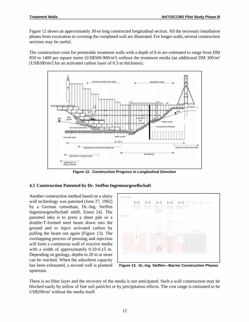
Figure 12. Construction Progress in Longitudinal Direction
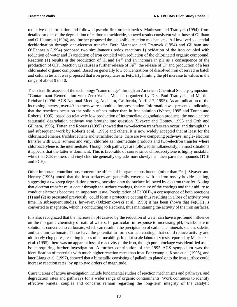
Figure 13. Dr.-Ing. Steffen—Barrier Construction Phases
Figure 12 shows an approximately 30-m long constructed longitudinal section. All the necessary installationphases from excavation to covering the completed wall are illustrated. For longer walls, several constructionsections may be useful.
The construction costs for permeable treatment walls with a depth of 8 m are estimated to range from DM850 to 1400 per square meter (US$500-900/m²) without the treatment media (an additional DM 300/m²[US$180/m²] for an activated carbon layer of 0.3 m thickness).
4.5 Construction Patented by Dr. Steffen Ingenieurgesellschaft
Another construction method based on a slurrywall technology was patented (June 27, 1992)by a German consultant, Dr.-Ing. SteffenIngenieurgesellschaft mbH, Essen [4]. Thepatented idea is to press a sheet pile or adouble-T-formed steel beam down into theground and to inject activated carbon bypulling the beam out again (Figure 13). Theoverlapping process of pressing and injectionwill form a continuous wall of reactive mediawith a width of approximately 0.10-0.15 m.Depending on geology, depths to 20 m or morecan be reached. When the adsorbent capacityhas been exhausted, a second wall is plannedupstream.
There is no filter layer and the recovery of the media is not anticipated. Such a wall construction may beblocked easily by inflow of fine soil particles or by precipitation effects. The cost range is estimated to beUS$200/m² without the media itself.

Treatment Walls NATO/CCMS Pilot Study Phase III
13
Figure 14. Large Diameter BoreholeConstruction Method
Figure 15. Sax+Klee GmbH, Germany
Figure 16. Funnel and Gate System,University of Waterloo
4.6 Large Diameter Borehole Construction Method
This construction method is used in the U.S. as well as in Germany. Mull und Partner, Hannover, Germany,has proposed a continuous overlapping iron-filled wall in Nordrhein-Westfalen to prevent downstreamcontamination of chlorinated hydrocarbons emitted by a laundry.
Usually, borehole diameters from 0.8-1.6 m arechosen. Individually located bore holes, establishedin several lines are known as an “iron-fence.” Themethod is applicable for continuous walls, if thebore holes overlap, or for gate constructions. Depthsto 20-25 m may be reached with no problems. Byoverlapping the bore holes, a loss of approximately15-20 % of the filling material has to be allowed.Depending on the geology, in most cases steel pipeshave to be used for stability of the borehole duringexcavation. This construction method is shown inFigure 14.
The costs for this method are US$300-500/m²,excluding filling materials.
4.7 Method developed by Sax+Klee, Germany
The German construction company, Sax+KleeGmbH, Mannheim, has developed a modified largediameter borehole construction method for a funnel-and-gate PRB system. The innovative approachincludes using bore holes filled with impermeableclay to connect the funnel sheet pile walls with thegate structure. Also new is the proposed installationof an interior well screen with four wings to createa filler zone between the surrounding soils and thereactive media (Figure 15).
The costs for a 40 m wide and 19 m deep gateconstruction are estimated to be approximatelyUS$1,400/m².
A filling material of petroleum activated carbon isproposed for a site with groundwater contaminatedwith petroleum hydrocarbons and aromatics(BTEX). The site is a former U.S. Army tank farm.
4.8 “Funnel and Gate” Patented by University ofWaterloo
The funnel and gate method (Figure 16) has beenpatented worldwide since April 23, 1992, for theUniversity of Waterloo, Canada [5].

Treatment Walls NATO/CCMS Pilot Study Phase III
14
“Contaminated groundwater is treated in situ, by funnelling the water through a gate or gates in a watertightin-ground wall. Treatment material in the gate breaks down the contaminant, or otherwise removes thecontaminants from the flowing water. A removable caisson is first driven into the ground, excavated, andthen a receptacle, for the treatment material, is lowered into the hollow interior.”
The patent itself shows a wide variety of construction elements, such as caissons made of steel (receptacles),slurry and sheet pile waterproof walls, removable baskets in the receptacle, removable caissons, etc.
Costs for the construction methods proposed by the University of Waterloo may vary in the range ofUS$200-1,000/m².
4.9 Bio-Polymer Slurry Trenching Technique
Geo-Con, a subsidiary of Woodward-Clyde, reported (December 23, 1997) the performance of a funnel-and-gate project for the U.S. Department of Energy, Oak Ridge, as follows:
Geo-Con recently completed what we believe to be the first permeable reactive wall installed usingthe bio-polymer slurry trenching technique. The reactive gate consists of a 30-foot (900 cm) ironfiling “gate,” with two 100-foot (30 m) wings composed of pea gravel. The system is 2 feet (60 cm)wide and extends down to bedrock, which is approximately 26 feet (780 cm) below ground surface.
The purpose of the permeable reactive wall is to collect a plume of groundwater contaminated with volatileorganic compounds (VOCs). The trench intercepts the groundwater, funneling it through the pea gravel tothe iron filing gate. As the groundwater passes through the filing gate, the VOCs are removed.
This project was originally contracted to another company, to be built by excavating dry and backfilling withthe filings and pea gravel. Upon nearing completion of the first cut-approximately 20 feet (600 cm) deep,the trench collapsed. Geo-Con proposed to complete the project using a bio-polymer slurry to maintaintrench stability during gravel and iron filling installation. Geo-Con was able to complete the project in threedays, expediting the project schedule and providing a considerable cost saving over other installationmethods. [6]
The author estimates costs for this technique to be in the range of US$300-500/m², not including the fillingmaterials.
4.10 Other Construction Methods
The following listing of other construction methods under discussion or developed for the installation ofPermeable Reactive Barriers is not complete; it reflects the knowledge of the author about actualinformation.
• Enviro Wall is a trademark of Barrier Member Containment Co. Ltd. and Argonne National Laboratory.By help of a guide box installation, an HDPE geomembrane will be installed, and a groundwatercollection and redistribution system will guide groundwater to a pass through module. The open trenchwill be refilled with site soil and capped with bentonite after installation of membranes and horizontalcollection systems.
• The PRB Action Team reports studies using high pressure jet grouting systems to create eitherpermeable grout diaphragms or columns [7]. Overlapping these structures creates longer, continuousbarriers. In a field study, two grout formulas have been tried: a resin/granular cast iron slurry and a

Treatment Walls NATO/CCMS Pilot Study Phase III
15
kaolinite clay/iron slurry. Also, deep soil mixing and hydrofracturing (horizontal and vertical) are underdiscussion in the U.S. as alternative installation methods.
• Envirotreat Ltd., UK, is currently working on the development of active containment systems usingspecial clay materials. Addition of reactive materials to clay barriers is also under investigation.Overlapping large diameter bore holes are one of the construction methods is considered to beapplicable.
• Several German engineering companies have proposed the installation of gates in the form of concretestructures for horizontal or vertical through-flow (Peschla und Rochmes, Edenkoben, and WCIUmwelttechnik, Essen). These are conventional underground concrete structures, caissons, or chambersthat contain removable reactive media. These buildings are expensive and limited to use as single gatestructures.
• WCI-Umwelttechnik GmbH is working on a deep wall construction method using modified slurry walltechniques with additional caissons as containment for the reactive media.
Finally, the injection of reactive material into the unsaturated or saturated zone, not forming a definedstructure, is a potential method, but not discussed in this report.
5. Costs
Table 2 presents a rough overview to costs for the several construction techniques mentioned. They do notinclude the filling material. They also depend on national markets and on actual/future experience anddevelopments. Some of the actually methods may disappear in the near future, and others may showeconomical advantages. Generally, we need more field testing and full-scale experience than we now have.
Table 2: Cost Overview
Construction method Max Cost RangeDepth [m] [US$/m²]
4.1 Peat-filled trench 5 10 -1004.2 Solid-free trench 10 200 - 4004.3 Open trench construction 10 100 - 2004.4 WCI-treatment wall 12 500 - 9004.5 Dr. Steffen’s patent 20 2004.6 Large diameter borehole 20-25 200 - 5004.7 Sax+Klee system 20 1000 - 15004.8 Funnel and Gate 20 200 - 10004.9 Bio-polymer slurry 30 300 - 5004.10 Other construction methods 10 100 - 300
20 200 - 100030 500 - 1500
6. Conclusions
In our estimation, it is too early to evaluate construction methods in general. They strongly depend on therequired depth, hydrogeology, contaminants, remediation targets, etc. Most of the construction methodsdiscussed are unproven in relation to PRBs, or are under testing.

Treatment Walls NATO/CCMS Pilot Study Phase III
16
A wide variety of construction elements are available. The future will show which systems are mostapplicable to shallow and deep aquifers and that are economically sound.
Full-scale applications and field tests will be helpful in establishing the innovative PRB technology as aproven and available remediation alternative. Besides the research and development activities regardingeffective reactive media, we have to deliver inexpensive, durable construction techniques to install(recoverable) reactive media in the contaminated groundwater plume.
7. References
[1] United States Patent Number 5,057,0227, Cohen, University of South Carolina, Columbia, S.C.,October 15, 1991.
[2] Patentschrift DE 41 05 987 C2, Haldenwang, Eichhorn, February 26, 1991 “Vorrichtung und Verfahrenzur in situ-Behandlung verunreinigter Grundwässer”.
[3] Patentschrift DE 44 25 061 C1, WCI-Umwelttechnik GmbH, July 15, 1994 “PermeablesBehandlungsbett zur Reinigung kontaminierter Grundwasserströme in situ”.
[4] Patentschrift DE 4221 198 C2, Dr.-Ing. Steffen Ingenieurgesellschaft mbH, June 27, 1992 “Verfahrenzum Entfernen von wasserlöslichen sorbierbaren Schadstoffen aus einem abströmenden Grundwasserin der Umgebung eines Kontaminationsherdes”.
[5] International Patent W093/22241, Cherry, Vales, Gillham, University of Waterloo, Canada, April 23,1992 “System for Treating Polluted Groundwater”.
[6] Geo-Con, internal company information, not published, December 1997.
[7] Permeable Reactive Barrier Action Team, Summary of the Remediation Technologies DevelopmentForum, Virginia Beach, Virginia September 18-19, 1997.
Discussion
It was suggested that treatment walls may not need to intercept all of the contaminated groundwater, dueto the expense of constructing the walls, and could be designed to treat (for example) only 90% of thegroundwater flow. This would make the technology cheaper and more appealing. Beitinger agreed that suchwalls can be constructed (e.g., an iron fence or non-overlapping borehole reactors), but the decision isusually based on whether the regulating authority would permit continued flow of untreated water.

Treatment Walls NATO/CCMS Pilot Study Phase III
Submitted for publication in: Proceedings, American Society of Civil Engineers, 1998.1
University of Waterloo, Department of Earth Sciences, 200 University Avenue W., Waterloo, ON N2L 3G1, Canada,2
tel: +519-888-4658, fax: +519-746-7484, e-mail: [email protected]
17
Development of Iron-Based Reactive BarrierTechnologies for Remediation of Chlorinated Organic
Contaminants in Groundwater1
Robert W. Gillham2
Abstract
Granular iron was not recognized as an effective reductant for promoting the dechlorination of halocarbonsin aqueous solution until the late 1980s. Furthermore, the suggestion that granular iron be used, for in situremediation of groundwater containing halocarbons was initially met with a high degree of skepticism. Inthe intervening years, the use of granular iron for groundwater remediation has emerged as a new andsignificant environmental technology. This paper outlines some of the major contributions that have led tothe growing scientific and market acceptance of the technology.
Introduction
Recognizing the limitations of pump-and-treat methods for groundwater remediation (NAS, 1994),considerable attention has now turned to the use of in situ permeable reaction barriers (PRBs). An earlyreview of this topic (prepared in 1992) is given in Gillham and Burris (1997). In this concept, a permeable“wall” containing the appropriate reactants is constructed across the path of a contaminant plume. As thecontaminants pass through the reactive material under passive groundwater flow, they are removed bychemical and/or physical processes. Proponents of PRBs cite reduced capital cost, low operating andmaintenance costs, and conservation of water and energy among the potential advantages over pump-and-treat systems.
The use of granular iron for removal of chlorinated organic contaminants has led the interest in PRBs. Withinitial recognition in 1989, this concept is now emerging as a significant technology for groundwaterremediation. This paper summarizes the major steps in both the scientific understanding and acceptance,and in the commercial development of the technology.
Scientific Development
In studies of the effect of sampling-well materials on sample integrity, (Reynolds et al., 1990) it wasobserved that the concentration in aqueous solution of several chlorinated organic contaminants declinedwhen in contact with certain metals. Though this observation was made in 1984, it was not until 1989 thatthe potential significance with respect to groundwater remediation was recognized. Further testingconfirmed the earlier results and revealed various aspects of the process. In particular, based on our earlyunderstanding of the reactions, the passive in situ use of granular iron was proposed as an alternative forremediation of groundwater containing halocarbons. Response to publication of the early experimentalresults and concepts (Gillham and O’Hannesin, 1992) generally varied from skepticism to disbelief.
A degree of credibility and the attention of the scientific community was gained through two paperspublished in 1994. Gillham and O’Hannesin (1994) showed a wide range of contaminants to degrade, inthe presence of granular iron, at rates that are several orders of magnitude greater than natural abioticdegradation rates reported in the literature. Evidence was presented to indicate that the reaction was abiotic
Treatment Walls NATO/CCMS Pilot Study Phase III
18
reductive dechlorination and followed pseudo-first order kinetics. Matheson and Tratnyek (1994), fromdetailed studies of the degradation of carbon tetrachloride, showed results consistent with those of Gillhamand O’Hannesin (1994), and further proposed three possible reaction mechanisms. All involved sequentialdechlorination through one-electron transfer. Both Matheson and Tratnyek (1994) and Gillham andO’Hannesin (1994) proposed two simultaneous redox reactions 1) oxidation of the iron coupled withreduction of water and 2) oxidation of iron coupled with reduction of the chlorinated organic compound.Reaction (1) results in the production of Hand Fe and an increase in pH as a consequence of the2
2+
production of OH. Reaction (2) causes a further release of Fe , the release of Cl and production of a less- 2+ -
chlorinated organic compound. Based on generally low concentrations of dissolved iron observed in batchand column tests, it was proposed that iron precipitates as Fe(OH), limiting the pH increase to values in the2
range of about 9 to 10.
The scientific aspects of the technology “came of age” through an American Chemical Society symposium“Contaminant Remediation with Zero-Valent Metals” organized by Drs. Paul Tratnyek and MartineReinhard (209th ACS National Meeting, Anaheim, California, April 2-7, 1995). As an indication of theincreasing interest, over 40 abstracts were submitted for presentation. Information was presented indicatingthat the reactions occur on the solid surfaces rather than in free solution (Weber, 1995 and Totten andRoberts, 1995); based on relatively low production of intermediate degradation products, the one-electronsequential degradation pathway was brought into question (Sivavec and Homey, 1995 and Orth andGillham, 1995). Totten and Roberts (1995) showed that two-electron transfers can occur, and through thisand subsequent work by Roberts et al. (1996) and others, it is now widely accepted that at least for thechlorinated ethenes, trichloroethene and tetrachlorothene, there are two competing pathways, single- electrontransfer with DCE isomers and vinyl chloride as intermediate products and two-electron transfer wherechloroacetylene is the intermediate. Though both pathways are followed simultaneously, in most situationsit appears that the latter is dominant. This is favorable of course since chloroacetylene is highly unstable,while the DCE isomers and vinyl chloride generally degrade more slowly than their parent compounds (TCEand PCE).
Other important contributions concern the affects of inorganic constituents (other than FeE). Sivavec andHorney (1995) noted that the iron surfaces are generally covered with an iron oxyhydroxide coating,suggesting a two-step degradation process, sorption onto the surface followed by electron transfer. Notingthat electron transfer must occur through the surface coatings, the nature of the coatings and their ability toconduct electrons becomes an important issue. Precipitation of Fe(OH), a consequence of both reactions2
(1) and (2) as presented previously, could form a protective coating thus resulting in a loss of activity overtime. In subsequent studies, however, (Odziemkowski et al., 1998) it has been shown that Fe(OH)is2
converted to magnetite, which is conducting to electrons, thus maintaining the activity of the iron surfaces.
It is also recognized that the increase in pH caused by the reduction of water can have a profound influenceon the inorganic chemistry of natural waters. In particular, in response to increasing pH, bicarbonate insolution is converted to carbonate, which can result in the precipitation of carbonate minerals such as sideriteand calcium carbonate. These have the potential to form surface coatings that could reduce activity andultimately clog pores, resulting in loss of permeability. In pilot-scale laboratory tests reported by Mackenzieet al. (1995), there was no apparent loss of reactivity of the iron, though pore blockage was identified as anissue requiring further investigation. A further contribution of the 1995 ACS symposium was theidentification of materials with much higher reaction rates than iron. For example, Korte et al. (1995), andlater Liang et al. (1997), showed that a bimetallic consisting of palladium plated onto the iron surface couldincrease reaction rates, by up to two orders of magnitude.
Current areas of active investigation include fundamental studies of reaction mechanisms and pathways, anddegradation rates and pathways for a wider range of organic contaminants. Work continues to identityeffective bimetal couples and concerns remain regarding the long-term integrity of the catalytic

Treatment Walls NATO/CCMS Pilot Study Phase III
19
enhancement. Certainly the most pressing practical issue is the long-term performance of zero-valent ironin natural subsurface environments. Various research groups are continuing to investigate the changes overtime in the surface characteristics of iron in contact with various types of groundwater, and the nature andconsequences of precipitates that may form.
Commercial Development
As discussed in NAS (1997) and summarized in Macdonald (1997), many companies developed for thepurpose of marketing new environmental technologies have had a remarkably poor record of success. Inparticular, the requirement for regulatory acceptance of new technologies and the fact that the incentivesfor site owners generally encourage the delay of remedial action are significant contributors to a sluggishenvironmental market. The in situ iron technology is marketed by EnviroMetal Technologies Inc. (ETI)under a licensing agreement with the University of Waterloo. ETI was incorporated in 1992, at a time whenthere was a high degree of skepticism. In addition, because capital costs of installing an in situ iron treatmentsystem are not particularly advantageous, the main financial incentive is in greatly reduced long-termoperating and maintenance costs. Clearly, in 1992, it was not possible to demonstrate these savings.
The first important contribution to market access was the development, in 1992, of an in situ demonstrationat Canadian Forces Base Borden. The early results of that test showed that the dechlorination reaction wouldindeed proceed in situ, and each passing year of consistent performance, raised the level of confidence inthe efficacy of the technology. As reported in O’Hannesin and Gillham (1998) this facility performedconsistently and effectively over the five- year duration of the test. The second major contribution to marketdevelopment was the first in situ treatment system at a commercial site Yamane et al., 1995). This occurredin late 1994 and early 1995, at a time when general knowledge of the technology was at a low level andlong-term in situ performance remained as a significant unresolved question. The interest of the client innew technologies, and willingness to support the testing required to develop the design was critical to thisinitial application, and a significant contribution to market development.
Another important development was the identification of large quantities of granular iron available atreasonable cost. Currently there are three major suppliers, all of whom recover cuttings from metalmachining and fabrication operations, treat and grade the materials and resell the product for a variety ofcommercial uses. These materials have proven to be highly effective as the reductant in the dechlorinationprocess.
While regulatory concerns can slow technology implementation, regulators, particularly the EPA, havecontributed in a major way to the growing acceptance of the iron technology. In addition to favorable resultsreported by EPA researchers, an above-ground demonstration installed in New Jersey in 1995 wasmonitored under the EPA SITE program, resulting in a favorable report (US EPA, 1997). Similarly, an insitu demonstration in New York State promises to result in a favorable report under the SITE program(anticipated in 1998). Inclusion of PRBs, as a Working Group under the Remediation Technology
Development Forum has also played an important role in disseminating information concerning PRBsgenerally and the use of granular iron in particular.
ETI currently reports the installation of ten demonstration facilities and twelve full-scale treatment facilities.While the numbers remain small, the trends suggest a growing awareness and acceptance of the technology.In particular, all recent installations have been full-scale, the time between initial contact andimplementation is decreasing and the number of inquiries continues to increase.
Treatment Walls NATO/CCMS Pilot Study Phase III
20
References
Gillham, R.W. and O’Hannesin, S.F., 1992. Metal-catalyzed abiotic degradation of halogenated organiccompounds. IAH Conference: In Modern trends in hydrogeology, Hamilton, Ontario, May 10-13, pp.94-103.
Gillham, R.W. and O’Hannesin, S.F., 1994. Enhanced degradation of halogenated aliphatics by zero-valentiron. Ground Water, Vol.32, No.6, pp. 958-967.
Gillham, R.W. and Burris, D.R., 1997. Recent developments in permeable in situ treatment walls forremediation of contaminated groundwater. Chapter 21: Subsurface Restoration, Eds. Ward, C.H.,Cherry, J.A. and Scalf, M.R., Ann Arbor Press, Inc., Chelsea, Michigan, pp 343-356.
Liang, L., Korte, N., Goodlaxson, J.D., Clausen, J., Fernando, Q. and Muftikian, R., 1997. Byproductformation during the reduction of TCE by zero-valent iron and palladized iron. Ground WaterMonitoring and Remed., Winter, pp.122-127.
Macdonald, J.A., 1997. Hard times for innovative cleanup technology. Environmental Science andTechnology, Vol.31, No.12. pp.560-563.
Mackenzie, P.D., Baghel, S.S., Eyholt, G.R., Horney, D.P., Salvo, J.J. and Sivavec, T.M., 1995. Pilot-scaledemonstration of reductive dechlorination of chlorinated ethenes by iron metal. In proceedings of 209thAmerican Chemical Society National Meeting, Anaheim, CA, Vol.35, No.1, pp.796-799.
Matheson, L.J. and P.G. Tratnyek, 1994. Reductive dehalogenation of chlorinated methanes by iron metal.Environ. Sci. Technol., Vol.28, No.12, pp. 2045-2053.
National Academy of Sciences, 1994. Alternatives for ground water cleanup. Report of the NationalAcademy of Science Committee on Ground Water Cleanup Alternative. Washington, D.C., NationalAcademy Press.
National Academy of Sciences, 1997. Innovations in Groundwater and soil cleanup: From concept tocommercialization. National Research Council,
Committee on Innovative Remediation Technology, National Academy Press, Washington, D.C.
Odziemikowski, M.S., T.T. Schuhmacher, R.W. Gillham, and E.J. Reardon, 1998. Oxide Film Formationon Iron in Simulating Groundwater Solutions: Raman Spectral and Electrochemical Studies. CorrosionStudies (in press).
O’Hannesin, S.F. and Gillham, R.W., 1998. Long-term performance on an m situ “iron wall” forremediation of VOCs. Ground Water, Vol.36, No.1, pp. 164-170.
Orth, S. and Gillham, R.W., 1996. Dechlorination of trichloroethene in aqueous solution using Fe.0
Environmental Sci. and Technol., Vol.30, No.1, pp.66-71.
Reynolds, G.W., Hoff, J.T. and Gillham, R.W., 1990. Sampling bias caused by materials used to monitorhalocarbons in groundwater. Environmental Science and Technology, Vol.24, No.1, pp.135-142.

Treatment Walls NATO/CCMS Pilot Study Phase III
21
Roberts, A.L, Totten, L.A., Arnold, W.A., Burris, D.R., and Campbell, T.i, 1996. Reductive elimination ofchlorinated ethylenes by zero-valent metals. Environmental Science and Technology, Vol. 30, No.8,pp.2654-2659.
Sivavec, T.M. and Horney, D.P., 1995. Reductive dechlorination of chlorinated ethenes by iron. Inproceedings of 209th American Chemical Society National Meeting, Anaheim, CA, Vol.35, No.1,pp.695-698.
Totten, L.A. and Roberts, A. L., 1995. Investigating electron transfer pathways during reductivedehalogenation reactions promoted by zero-valent metals. In proceedings of 209 American Chemicalth
Society National Meeting, Anaheim, CA, Vol.35, No.1, pp.706-708.
Weber, E.J., 1995. Iron-media reductive transformations: Investigation of reaction mechanism. Inproceedings of 209 American Chemical Society National Meeting, Anaheim, CA, Vol. 35, No.1,th
pp.702-705.
Yamane, C.L, Warner, S.D., Gallinatti, J.D., Szerdy, F.S., Delfino, T.A., Hankins, D.A., Vogan, J.L., 1995.Installation of a subsurface groundwater treatment wall composed of granular zero-valent iron. Inproceedings of 209 American Chemical Society National Meeting, Anaheim, CA, Vol.35, No.1,th
pp.792-795.
United States Environmental Protection Agency, 1997. Metal-enhanced dechlorination of volatile organiccompounds using an aboveground reactor: Innovative technology evaluation report, Office of Researchand Development, Washington, D.C., EPA/540/R-96/503.
Discussion
Cores collected from two commercial sites showed little change in bacterial activity over the upgradientinterface; however, no information was collected for the downgradient side of the treatment wall.
Although there were numerous monitoring wells situated throughout the Borden site, there was nonoticeable affect on the hydrologic flow regime. Most are small-diameter shallow wells that were installedfor another purpose prior to constructing the wall.
Treatment walls can be used in low-permeability or fractured-bedrock aquifers if there is a measurablegradient. Fractured bedrock is more difficult, although Gillham mentioned a treatment wall currently beinginstalled at a site with fractured bedrock. The fractures are being sealed by jet grouting, and reactivetreatment materials are being jetted into the fractures. Hydrofracturing can be used to widen fractures beforeinjecting materials.
There is a sharp pH gradient within the iron wall. The pH-neutral groundwater typically increased to pH 9-10 within the first 10-15 cm of the upgradient side of the wall.

Treatment Walls NATO/CCMS Pilot Study Phase III
6 Rue De Wattford, F92000 Nanterre, France, tel: 33/14-7764-262, fax: 33/14-9069-734, e-mail: gerard.evers@1
soletanche-bachy.com
22
Practical Solutions for the Treatment of Polluted Groundwater
Gérard Evers1
The remediation of polluted sites and its treatment constitute a complex problem, and every case is special.Many solutions are proposed to clean or to isolate pollutants, such as biological treatment, soil washing orflushing, electrochemical treatment, vacuum extraction, stabilization, or containment.
Matching a site and a remediation technique depends on many parameters. Design studies for theimprovement of these sites take into account not only the chemical context, but also the geology andhydrogeology as well. In many cases, it is necessary to preserve the groundwater flow. Soletanche Bachy developed several innovative solutions in this field. Drainage trenches, used either aloneor in combination with cut-off walls, allow controlling and extracting pollutants while the local groundwaterregime is maintained.
Extensive research over the last ten years about the behavior of dissolved pollutants, organic and mineral,ended up with a variety of materials able to trap pollutants in drainage conditions (ECOSOL and IRISmaterials), and in a process of underground water seepage control and treatment called the “drain panelprocess.”
Trapping mechanisms
Several physical and chemical mechanisms are involved to trap pollutants in groundwater. Precipitation,adsorption, and ionic exchange are the most important.
Precipitation
Chemical precipitation is mainly used to eliminate dissolved heavy metals, such as iron, nickel, copper, lead,trivalent chromium, and hexavalent chromium.
These cations are often precipitated in the form of metallic hydroxides in chemical reactions controlled bythe pH. In cement-based materials, lime solubility dictates a pH of 12-12.5. However, this reserve of alkaliin cements, although large, is not infinite, and alkaline buffers may be incorporated in trapping materialsto extend their precipitation ability with time. In some cases, specific reagents are employed to react withpollutants and to precipitate into a insoluble mineral forms.
Adsorption
Adsorption is a physical mechanism based on the properties of some porous materials to fix molecules ontheir surface. Specific surface governs this mechanism. Attractive forces have different origins:
• physical bonds by pores of similar sizes to the target molecules; • Van der Waals forces (electrical trapping) is applicable to polarized molecules; • surface affinity—hydrophobic organic molecules have affinities for sites on activated carbon.

Treatment Walls NATO/CCMS Pilot Study Phase III
ECOSOL and DRAIN PANEL are patented.2
23
Adsorption on activated carbon is a widely used method for removing organic pollutants dissolved in wastewater. Adsorption capacity values vary depending on the compounds to be removed. For instance,adsorption capacity of chlorophenol is six times higher than that of butylacetate in same conditions. Someclays are able to adsorb cations such as cadmium, strontium, mercury, nickel, and zinc.
Ion exchange
This process is employed for removing dissolved anions in polluted groundwater. Removal method can bepercolation through specific resins or clays. This mechanism is well adapted to eliminating cyanides. Twoprocesses are described here to implement these pollutant trapping drainage materials: the drain panel andthe drainage trench.
The Drain Panel Process2
In order to avoid spreading an industrial or accidental pollutant, watertight confinement barriers are ofteninstalled together with a pumping system, to keep the water table within the confined area below the outsidewater table. A water treatment installation will clean the pumped water before returning it to the ambientgroundwater. But this classical concept has several inconveniences, which can be solved by the drain panelprocess.
The drain panel process consists of drainage panels separated by watertight cement slurry panels. A conduit,at the bottom of the watertight panel, establishes the hydraulic continuity between the two drainage panelson either side. A valve, operated from the surface, can be installed to regulate this hydraulic continuity.
The drain panel can be built in combination with the classical confinement barrier, or in combination witha partial barrier, which will then form the so-called “funnel-and-gate” solution. The drain panel system canbe used to considerable depths (30 meters or more).
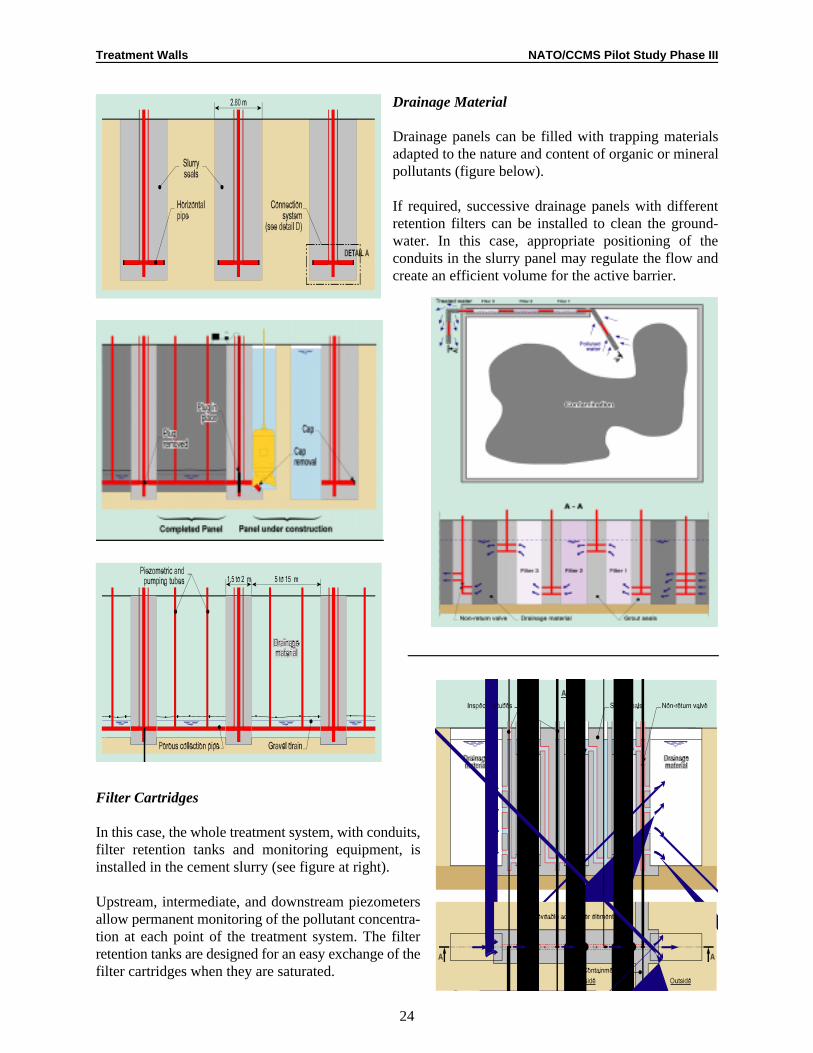
Construction Method
The watertight cement slurry panel is excavated first. When the excavation is completed, a horizontalconduit (200 to 400 mm diameter), linked to a vertical standpipe, is installed at the base of the panel. Thisconduit has destructible parts closed off with caps at both ends. A temporary inflatable plug avoids any flowthrough the conduit.
When the slurry has set, the adjacent drainage panels canbe excavated using a biodegradable drilling mud. Thesealing slurry, vertically covering the destructible partslocated at the ends of the conduit, is excavated, and thedestructible parts are cut, either by the excavation tool orby another suitable method.
When the excavation of the drainage panel is completed,it is filled with appropriate drainage material, andconductivity between drainage panels is established bywithdrawal of the temporary inflatable plug (next threefigures).
Treatment Walls NATO/CCMS Pilot Study Phase III
24
Drainage Material
Drainage panels can be filled with trapping materialsadapted to the nature and content of organic or mineralpollutants (figure below).
If required, successive drainage panels with differentretention filters can be installed to clean the ground-water. In this case, appropriate positioning of theconduits in the slurry panel may regulate the flow andcreate an efficient volume for the active barrier.
Filter Cartridges
In this case, the whole treatment system, with conduits,filter retention tanks and monitoring equipment, isinstalled in the cement slurry (see figure at right).
Upstream, intermediate, and downstream piezometersallow permanent monitoring of the pollutant concentra-tion at each point of the treatment system. The filterretention tanks are designed for an easy exchange of thefilter cartridges when they are saturated.
Treatment Walls NATO/CCMS Pilot Study Phase III
25
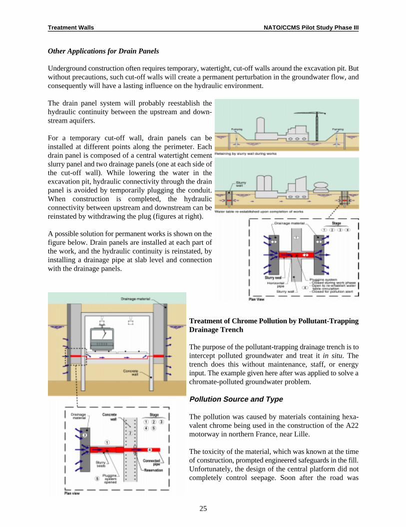
Other Applications for Drain Panels
Underground construction often requires temporary, watertight, cut-off walls around the excavation pit. Butwithout precautions, such cut-off walls will create a permanent perturbation in the groundwater flow, andconsequently will have a lasting influence on the hydraulic environment.
The drain panel system will probably reestablish thehydraulic continuity between the upstream and down-stream aquifers.
For a temporary cut-off wall, drain panels can beinstalled at different points along the perimeter. Eachdrain panel is composed of a central watertight cementslurry panel and two drainage panels (one at each side ofthe cut-off wall). While lowering the water in theexcavation pit, hydraulic connectivity through the drainpanel is avoided by temporarily plugging the conduit.When construction is completed, the hydraulicconnectivity between upstream and downstream can bereinstated by withdrawing the plug (figures at right).
A possible solution for permanent works is shown on thefigure below. Drain panels are installed at each part ofthe work, and the hydraulic continuity is reinstated, byinstalling a drainage pipe at slab level and connectionwith the drainage panels.
Treatment of Chrome Pollution by Pollutant-TrappingDrainage Trench
The purpose of the pollutant-trapping drainage trench is tointercept polluted groundwater and treat it in situ. Thetrench does this without maintenance, staff, or energyinput. The example given here after was applied to solve achromate-polluted groundwater problem.
Pollution Source and Type
The pollution was caused by materials containing hexa-valent chrome being used in the construction of the A22motorway in northern France, near Lille.
The toxicity of the material, which was known at the timeof construction, prompted engineered safeguards in the fill.Unfortunately, the design of the central platform did notcompletely control seepage. Soon after the road was
Treatment Walls NATO/CCMS Pilot Study Phase III
26
opened, there were indications of chrome (VI) in the seepage water at some spots.
In 1987, a company located below the motorway (downgradient of groundwater flow) reported chrome (VI)in its drainage water, and this pollution was accompanied by bare patches in the vegetation of the motorwaybank.
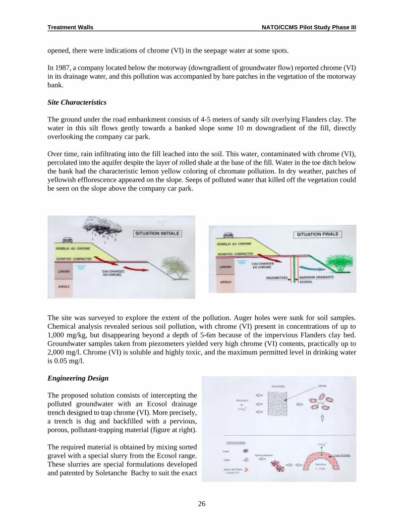
Site Characteristics
The ground under the road embankment consists of 4-5 meters of sandy silt overlying Flanders clay. Thewater in this silt flows gently towards a banked slope some 10 m downgradient of the fill, directlyoverlooking the company car park.
Over time, rain infiltrating into the fill leached into the soil. This water, contaminated with chrome (VI),percolated into the aquifer despite the layer of rolled shale at the base of the fill. Water in the toe ditch belowthe bank had the characteristic lemon yellow coloring of chromate pollution. In dry weather, patches ofyellowish efflorescence appeared on the slope. Seeps of polluted water that killed off the vegetation couldbe seen on the slope above the company car park.
The site was surveyed to explore the extent of the pollution. Auger holes were sunk for soil samples.Chemical analysis revealed serious soil pollution, with chrome (VI) present in concentrations of up to1,000 mg/kg, but disappearing beyond a depth of 5-6m because of the impervious Flanders clay bed.Groundwater samples taken from piezometers yielded very high chrome (VI) contents, practically up to2,000 mg/l. Chrome (VI) is soluble and highly toxic, and the maximum permitted level in drinking wateris 0.05 mg/l.
Engineering Design
The proposed solution consists of intercepting thepolluted groundwater with an Ecosol drainagetrench designed to trap chrome (VI). More precisely,a trench is dug and backfilled with a pervious,porous, pollutant-trapping material (figure at right).
The required material is obtained by mixing sortedgravel with a special slurry from the Ecosol range.These slurries are special formulations developedand patented by Soletanche Bachy to suit the exact

Treatment Walls NATO/CCMS Pilot Study Phase III
27
nature of the pollutants in question: radioactive elements, heavy metals, or organic compounds.
The gravel grains coated with pollutant-trapping slurry bond together so when the mix hardens, they forma rigid, porous structure through which water readily circulates. As the water seeps through, the chemicalpollutants are trapped on the film of hardened Ecosol formulation adhering to the grains of gravel.
Preparation of Ecosol Material
Several crucial parameters must be controlled whenpreparing the Ecosol material (see figure at right):
• Slurry/gravel weight ratio. This ratio must not betoo high, or the structure will not be sufficientlyporous. Nor must it be too low, or the gravel grainswill not be completely coated.
• Gravel size. For any given ratio between a unitvolume of slurry and the weight of gravel, a finergravel size will increase the active surface area of thestructure and reduce the thickness of the hardened slurry coating the gravel grains. This speeds up thetrapping reactions. On the other hand, it reduces the permeability of the structure, with the attendant riskof the pores becoming clogged.
• Selection of gravel and slurry. The bond between the film of hardened slurry and the gravel skeletonmust be sound and durable. The use of cement slurry and compatible gravels ensures durability,provided the same precautions are used as when designing standard concrete mixes.
• Rheological properties of slurry. The rheology of the freshly-mixed slurry paste must be designed toform a stable film coating the gravel. Therefore, apart from the specific pollutant-trapping substances,the mix must be designed so that the initial stiffness of the paste when the gravel is incorporated is nottoo great, nor too low.
• Slurry formulation. All types of Ecosol slurry can be used, provided their rheological properties aresuitable. The exact formulation of the slurry depends on pollutant types and concentrations and requiredtrapping capacity. The mix design is done in the laboratory. In this instance, the cumulative quantity ofchrome (VI) trapped per cubic meter of material could be determined. The Ecosol material is preparedby adding the various reagents in the composition at the mixer. This slurry is then used for coating thegravel. This is done in a truck mixer, so that the sorted gravel is delivered, the slurry added, the mixblended and the material delivered to the point of use all in one vehicle.
Trenching
On site, the trench is dug by a machine capable ofdigging to a depth of six meters. The mobile framecarries a chain and square-sided chute to guide thebackfill material from the top hopper into the trench. TheEcosol-coated gravel is brought in by the truck mixer tothe trench hopper, and the blended material flows likeconcrete. The result is a trench backfilled with Ecosol-coated gravel.

Treatment Walls NATO/CCMS Pilot Study Phase III
28
There were two zones: (A), where groundwater isintercepted by two trenches, because this area has thehighest chrome (VI) concentrations; and (B), where theflow is intercepted by a single trench.
The 0.25-m wide drainage trenches were widened atthe top. This extra thickness of trap potential deals withsurface water contaminated with chrome (VI) liable toseep into the aquifer.
Trench Performance Monitoring
Three piezometer profiles perpendicular to the trench monitor the trend in chrome (VI) concentration up-and downgradient of the of the trench. In total, 11 piezometers were installed, and each month, their waterlevels are recorded and water samples taken for laboratory analyses.
Analysis of these data confirm the existence of an hydraulic gradient, perpendicular to the trenches, fromthe embankment downwards to the car park location.
The following figure shows the chrome concentration upstream and downstream of the barrier, during the18-month observation period following the completion of the construction. The figure shows the goodperformance of the curtain: the chrome concentration remains at a high—but variable—level upstream ofthe curtain, while negligible concentrations are recorded downstream.
The measurements are still going on, and they confirm these findings. The Ecosol material confers a hightrap potential, around 15 kg of chrome (VI) per linear meter of trench.

Treatment Walls NATO/CCMS Pilot Study Phase III
29
Discussion
In response to a question, Evers explained that the treatment wall was excavated using a trenching machinecapable of excavating only to a depth of 10 m. The overall problem with the permeable treatment wall is thatthe reactive material is expensive (US$800/m), but not all of it is receiving contaminated groundwater.3
Because the soil is not uniform, there are preferential flow pathways, and approximately 10% of the wallhandles 90% of the contaminated groundwater. The advantage of the funnel-and-gate system is havingsuccessive reactive materials that receive contaminated groundwater flow.
There are at least three options for constructing a treatment wall to optimize cost-efficiency: (1) constructone continuous trench and fill it with a mixture of iron and sand; (2) use pea gravel screens upgradient toaverage the flow rate through the wall; or (3) construct a wall of varying thickness to account for variationsin groundwater flow. As long as substantial information on groundwater flow was available, plans can bemade for treatment walls having variable thicknesses. Generally, however, funnel-and-gate technology hasan advantage in evening out flow through the wall, but may magnify uncertainties.
There was some concern that if the hydrology of a site is not understood, use of a funnel-and-gate systemcan retard normal groundwater flow, causing an increase in upgradient thickness of the water. Thehydrology of a site must be modeled carefully prior to constructing a treatment wall. Modeling and thedesign of a funnel-and-gate system can be very expensive, perhaps accounting for up to 20% of the overallconstruction costs (compared to only 10% for slurry walls).

AB
C
1 .0 7 1 .2 3
1 1 .8
0 .1 2 0 .50 .0 3 2
0
1 0
A Fe [m 2/g ]
t 1/2n [h*m 2/m L ]
Treatment Walls NATO/CCMS Pilot Study Phase III
Institut für Wasserbau, Lehrstuhl für Hydraulik und Grundwasser, University of Stuttgart, Pfaffenwaldring 61, 705501
Stuttgart, Germany, tel: 49/711-685-4714, fax: 49/711-685-7020, e-mail: [email protected]
30
Figure 2.
Reactive MaterialsDegradation of TCE at Zero-Valent Iron:
Chemical Processes Effecting the Design and Performanceof Permeable, Reactive Fe(0) Walls
Wolfgang Wüst, O. Schlicker, and A. Dahmke1
Permeable reactive walls present a cost-effective alternative to classical pump-and-treat technologies for theremoval of dissolved contaminants from groundwater plumes, provided that a fairly passive long-termperformance can be guaranteed. Many materials are under research for use in such reactors, but zero-valentiron has been studied most intensely, since it is commercially available at low costs, and a variety ofcontaminants can be immobilized by reduction reactions (Dahmke et al., 1997). Based mainly on the resultsof our own studies, we describe the degradation of chlorinated aliphatic hydrocarbons, the most importantapplication of Fe(0) reactors, and in this context, we discuss the chemical processes effecting the design andperformance of permeable reactive Fe(0) walls.
Degradation of chlorinated hydrocarbons with zero-valent iron is known to be a heterogeneous surfacereaction, and thus dechlorination can only take place after the chlorinated compound has been associatedat the iron surface (Matheson and Tratnyek, 1994). Kinetics is described as pseudo-first-order (k [1/h])obs
with respect to dissolved concentrations, and k is reported to be proportional to the iron surface (BET)obs
concentration (Gillham and O´Hannesin, 1994; Sivavec and Horney, 1995). Different commerciallyavailable irons show a broad variety in costs as well as physical properties (Figure 1).
Figure 1. Comparison of different irons
Iron Spec. surface area Porosity Costs Costssource [m/g] [%] [DM/t] [DM/m ]2 3
A 0.12 37 800 3,400B 0.5 58 450 1,400C 0.032 39 500 2,300D 0.63 0.74 300 600
Testing iron from different producers, we foundconsiderable differences in reactivity with respectto TCE degradation. Differences in iron surfacearea concentrations could not sufficiently accountfor it, since we normalized k to this parameterobs
(Figure 2). The normalized first-order rateconstants were in the same range as reported fordifferent iron sources in North America (Johnsonet al., 1996).There a various other parameters likeforeign elements and grain geometry that mayaffect reactivity. Even iron from the same sourceshowed differences in reactivity.
In low mineralized waters competitive, cathodicreactions may occur that can affect the performance of permeable, reactive Fe(0) walls. Oxygen

0 0 .2 0 .4 0 .6 0 .8 1 1 .2 1 .4 1 .6
VG as [m m ol/d /k g ]
a
b
d
G as deve lopm ent a t d iffe ren t com m erc ia l irons (a , b , d )in co lum n experim ents (O 2-sa tura tion , low m in . w ater)
p H 4 / n o TC E
p H 7 / n o TC E
p H 7 / TC E in : 0 .1m M ol
C o m p o s it io n o f g a s e s fro m iro n s o u rc e b( in i t ia l p H 7 , lo w m in . w a te r )
1 E -3
1 E -2
1 E -1
1 E + 0
1 E + 1
1 E + 2
H 2 S um H C C H 4 C 2 H 6 C 2 H 4 C 3 H 8 C 3 H 6 C 4 H 1 0 H C > C 4
Gas
com
poun
d [%
mol
]
b (n o T C E ) b (T C E in : 0 .1 m M o l)
C o m p o s it io n o f g a s e s fro m iro n s o u rc e d( in i t ia l p H 7 , lo w m in . w a te r )
1 E -3
1 E -2
1 E -1
1 E + 0
1 E + 1
1 E + 2
H 2 S um H C C H 4 C 2 H 6 C 2 H 4 C 3 H 8 C 3 H 6 C 4 H 1 0 H C > C 4
d (n o T C E ) d (T C E in : 0 .1 m M o l)
Degradation kinetics of TCE for different inflowing concentrations
0
50
100
150
0 10 20 30 40
time [h]
C
in =13
0
500
1000
1500
C
in =14
TCEin [uMol]: 134 1450
kol [uMol/h]: 70.5+/-43.3 59.1+/-5.4
K1/2 [uMol]: 761+/-152 893+/-251
k1l [1/h]: 0.093 0.066
Treatment Walls NATO/CCMS Pilot Study Phase III
31
Figure 3.
Figure 4.
Figure 5.
Figure 6.
consumption was found to be fast in ourcolumn experiments, leading to a zone ofFe(III) precipitates at the column inlet,where hydraulic conductivity was reducedconsiderably (Dahmke et al. 1997). Effectson the degradation kinetics in Fe(0) reactorswere not detected, since only a fewcentimeters are affected by aerobiccorrosion. Formation of hydrogen byanaerobic corrosion is thermodynamicallyfavorable, but it depends strongly on thevoltage differential. For different irons, wefound dependence of reactivity on the ironsource, and pH at the inflow ranging fromno anaerobic corrosion to a strong gasproduction (Figure 3), which affectshydraulic conductivity and discharge ofgaseous TCE from the column. Hydrogen isthe dominating compound in the gas phase,and low-weight aliphatic hydrocarbons (totalHC) consisting exclusively of saturated HCaccount for less than 1 % mol gas, fairlyindependent of the iron source (Figure 4,Figure 5). TCE, at a concentration of 1mMol in the column feed, increases themolar fraction of the total HC to 1-3 %, andshort-chain unsaturated compounds (ethene,propene) appear in the HC pattern,accounting for TCE degradation. Furthercolumn experiments discussed below wereperformed with iron from a source that wasfound to have the highest voltage differentialwith respect to anaerobic corrosion, and afairly high normalized k .obs
Looking at the dechlorination kinetics in more detail,we found that the degradation rate was levelling offat a higher concentration due to saturation of reactivesites at the iron surface. An enhanced modelaccounting for first-order sorption, desorption, andreaction of sorbed TCE (Figure 6, Figure 7) wasfitted to the data with good success by theAQUASIM model. Parameters for zeroth- and first-order kinetics with respect to dissolved TCE-concentration are estimated. Since the dominantchlorinated intermediate, cis-DCE, did not exceed1% of the initial TCE concentration, first-orderbuild-up and degradation was found to be sufficient
to fit the measured data. Neither the intermediate cis-DCE nor the kinetics of parent TCE were significantlyaffected by a 5-fold increase in flow velocity (Figure 8). Cis-DCE as parent compound was degraded fasterthan TCE both in the zeroth-order and first-order region (Figure 9) in the column experiments. This is the

TCE and nitrate reduction at commercial iron
0.0
0.2
0.4
0.6
0.8
0 10 20 30 40
time [h]
C
3- , N
4 + [mM
6
8
10
12
14
NO3 NH4 TCE pH
Treatment Walls NATO/CCMS Pilot Study Phase III
32
Figure 7.
Figure 8.
Figure 9.
Figure 10.
reverse of the kinetics reported for these compounds(Johnson et al., 1996). In the binary componentexperiment, degradation rates of both compounds werereduced and competition between TCE and cis-DCEwill be discussed in more detail (Wüst et al., inpreparation). Since groundwater plumes contaminated
by chlorinated hydrocarbons usually contain a variety of compounds, competition between these singlecompounds has to be considered.
We were also testing the effect of different groundwater constituents (chloride, phosphate, sulfate, chromate,nitrate) on the degradation of TCE in column experiments, where the dissolved concentration of therespective groundwater constituent is gradually increased.
Abiotic nitrate (Figure 10) and chromate (data notshown) reduction at zero-valent iron were found tobe faster than the degradation of TCE. Nitrite as anintermediate could be detected only in traces, and allnitrate-N was reduced to the terminal N(-III).Reduction of 50 mg/l nitrate (German drinking waterstandard) can result in 13.3 mg/l ammonium enteringthe aquifer. Since pH is driven up to values greaterthan 10, ammonia is likely to form. High inflowingnitrate concentration leads to inhibition of both thereduction of nitrate and TCE by zero-valent iron.Consequently, the TCE concentration front ispassing through the iron column ahead of the nitrate front (Figure 11). Passivation is due to the formationof a considerable amount of iron precipitates (dissolved iron <0.01 mg/l). They are possibly more oxic dueto the higher redox potential both in solution and at the iron surface, and thus less conductive.

Effect of nitrate reduction on the degradation of TCE(PV: pore volumes permeated at 50 mg/L nitrate)
-3
-2
-1
0
ln(T
CE
/TC
Ein)
-3
-2
-1
0
0 5 10 15 20 25time [h]
(
3- / N
3- in)
TCE (no NO3- )
Effect of inflowing phosphate poncentration on the degradation of TCE at Fe
0.01
0.10
1.00
10.00
100.00
0 1 10 100PO4 in [mg/L]
K ol [uMol]
K 1l [1/h]
Effect of SO 4 at various inflowing concentrations on the degradation of TCE at Fe in column experiments
0
2
4
6
8
10
12
14
16
18
20
0 5 10 15 20 25 30 35 40
time [h]
TC
E [m
g/l]
1000 mg/L SO4
500 mg/L SO4
no SO4 (post)
100 mg/L SO4
no SO4 (ante)0
1
2
3
4
5
6
7
8
half
life
[h]
0 4 7 2 3 4 3 4 5
P o r e v o lu m e s s in c e i n f i lt r a t i o n o f
1 2 0 0 m g / L S O 42 - + 6 0 0 m g / L H C O 3
- + 1 0 0 m g / L N H 4 C l
Treatment Walls NATO/CCMS Pilot Study Phase III
33
Figure 11. Figure 12.
Figure 13. Figure 14.
Phosphate can affect the performance of iron walls only at higher inflowing concentrations (>1 mg/lphosphate). At 10 mg/l, we observed a decrease in both, zeroth- and first-order rate constant (Figure 12).100-mg/l phosphate in the feed further reduced zeroth-order degradation but so far did not effect first-orderdegradation in the back part of the column. Phosphate is sorbing, and forms vivianite, which was detectedby XRD in addition to magnetite. Formation of these precipitates could be predicted by the geochemicalequilibrium program PHREEQEC. In contrast to phosphate, loss of sulfate from solution could not beobserved. Considerable decrease in the degradation of TCE, however, was found at a concentration of 500mg/l sulfate (Figure 13). Higher sulfate concentration (1,000 mg/l) did not enhance the passivation of iron.
Sorption of sulfate was found to be reversible, and the column fully recovered after its desorption from theiron surface.
Abiotic sulfate reduction was not observed, but microbiological transformation to sulfide took place in oneof our columns to some extent. There we found degradation rates to increase (Figure 14), which we attributeeither to the enhancement of abiotic degradation because of sulfide formation (high electric conductivity)or to co-metabolic TCE degradation. Enhancement of reactivity was also attained by palladizing zero-valentiron. First-order kinetics was stable over a wide range of flow velocities and no maximum degradation rate(zeroth-order kinetics) could be detected even at high inflowing TCE concentrations (Figure 15). Increasingchloride concentrations confirmed the results known from aerobic anaerobic corrosion studies: the first-order rate constant increased by 2 in the range of 0-100 mg/l chloride (Figure 16).
In a low-mineralized groundwater environment, we expect long-term stability of dechlorination rates inpermeable, reactive Fe(0) walls and hydrocarbons as final products enter the aquifer. Description of thedegradation kinetics by a pseudo-first order model was not sufficient at higher TCE concentrations, wherezeroth-order kinetics was observed. We succeeded in fitting the data by a Monod-type model. Competition

Degradation of TCE at Palladized Iron (0.01% Pd)
k1l = 0.71+/- 0.12[ h-1 ] Co = 28mg/l v = 57cm/h
k1l = 0.70 +/- 0.16 [h-1 ] Co = 196mg/l v = 44cm/h
k1l = 0.75 +/- 0.06 [h-1 ]Co = 20.5mg/l v = 11cm/h
k1l = 0.79 +/- 0.25 [h-1 ]Co = 9.2mg/l v = 1.88cm/h-10.0
-9.0
-8.0
-7.0
-6.0
-5.0
-4.0
-3.0
-2.0
-1.0
0.0
0 1 2 3 4 5 6 7 8 9 10 11 12 13 14 15
k1l = 0.82 +/- 0.056 [h-1 ] Co = 228mg/l v = 11.6cm/h
0 1 1 3 2 4 1 4 4 5 0 6 1 6 9 6 9 7 4 7 7 7 9 8 50
1
2
3
4
5
6
no C l- 2 5 mg/l C l-
1 0 0 mg/l C l-5 0 0 m
Treatment Walls NATO/CCMS Pilot Study Phase III
34
Figure 15. Figure 16.
among different chlorinated compounds has to be expected as shown in the case of TCE and cis-DCE, andhas to be considered in the reactor design.
Redox-competitive inorganic groundwater constituents (oxygen, water, nitrate, chromate) can affect thedesign and performance of reactive iron walls considerably. Products like hydrogen gas and ammonia canbe formed and enter the aquifer. Iron precipitates can reduce permeability and reactivity. Under certainconditions, the concentration front of the chlorinated compounds is passing through the reactor due topassivation of zero-valent iron. These reactions may limit the scope of permeable reactive Fe(0) walls.
Inhibition observed by phosphate and sulfate seems to be of minor importance. At ambient groundwaterconcentrations, phosphate did not effect degradation kinetics of TCE, since it was precipitated at the frontof the column. No abiotic reduction was observed for sulfate (as for nitrate and chromate), but degradationrates were enhanced by microbiological sulfate reduction.
We expect that microbiological reduction of nitrate and chromate in the groundwater plume can reduce theimpact of these anions on the performance of reactive iron walls. Passivated walls can possibly beregenerated by chloride, which is known to break down passive films on zero-valent iron, and which wefound enhanced degradation rates in our experiments. We further assume that ascorbic acid will recoverdegradation rates due to its reducing and complexing properties.
References
Dahmke, A., Schlicker, O. & Wüst, W., 1997. Literaturstudie „Reaktive Wände-pH-Redoxreaktive Wände”Berichte LfU.
Matheson, L.J. & Tratnyek, P.G., 1994. Environ. Sci. Technol. 28, 2045-2053.
Gillham, R.W. & O´Hannesin, S.F., 1994. Ground Water, 32, 958-967.
Sivavec, T.M. & Horney, D.P., 1995, Prepr. Ext. Abs. ACS Special Symposium, Anaheim, 695-698.
Johnson, T.L., Scherer, M.M. & Tratnyek, P.G., 1996. Environ. Sci. Technol. 30, 2634-2640.
Wüst W., Schlicker, O. & Dahmke A. in prep. Kinetics of the Stepwise Degradation of TCE and cis-DCEat Commercial Iron in Batch and Column Experiments.
Dahmke, A., Schlicker, O. & Wüst, W., 1997. In: Grundwassersanierung 1997, IWS SR 28, 324-341.

Treatment Walls NATO/CCMS Pilot Study Phase III
35
Schlicker, O., Wüst, W. & Dahmke, A., 1998. TerraTech, 01, 43-46.
Discussion
Paul Bardos asked for an explanation of Figures 3, 4, and 5, which show a system with just oxygenatedwater and iron producing trace amounts of short-chained hydrocarbons. Wüst said that the iron contained3 percent carbon, which may have been the source of the hydrocarbons. Alternatively, there may have beenorganics in the gas phase that were reduced.
Hermann Schad also asked for an explanation of the apparent conversion of 100% of the nitrate to ammonia,while column experiments using site groundwater showed that much less nitrate had been converted. Wüstresponded that the difference is probably due to microbiological reactions that reduce more of the nitrate.
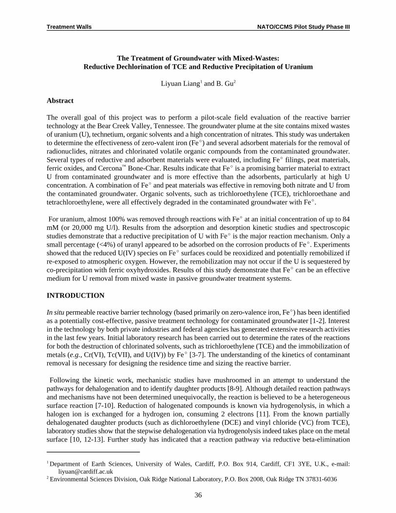
Treatment Walls NATO/CCMS Pilot Study Phase III
Department of Earth Sciences, University of Wales, Cardiff, P.O. Box 914, Cardiff, CF1 3YE, U.K., e-mail:1
[email protected] Environmental Sciences Division, Oak Ridge National Laboratory, P.O. Box 2008, Oak Ridge TN 37831-60362
36
The Treatment of Groundwater with Mixed-Wastes:Reductive Dechlorination of TCE and Reductive Precipitation of Uranium
Liyuan Liang and B. Gu1 2
Abstract
The overall goal of this project was to perform a pilot-scale field evaluation of the reactive barriertechnology at the Bear Creek Valley, Tennessee. The groundwater plume at the site contains mixed wastesof uranium (U), technetium, organic solvents and a high concentration of nitrates. This study was undertakento determine the effectiveness of zero-valent iron (FeE) and several adsorbent materials for the removal ofradionuclides, nitrates and chlorinated volatile organic compounds from the contaminated groundwater.Several types of reductive and adsorbent materials were evaluated, including FeE filings, peat materials,ferric oxides, and Cercona Bone-Char. Results indicate that FeE is a promising barrier material to extract™
U from contaminated groundwater and is more effective than the adsorbents, particularly at high Uconcentration. A combination of FeE and peat materials was effective in removing both nitrate and U fromthe contaminated groundwater. Organic solvents, such as trichloroethylene (TCE), trichloroethane andtetrachloroethylene, were all effectively degraded in the contaminated groundwater with FeE.
For uranium, almost 100% was removed through reactions with FeE at an initial concentration of up to 84mM (or 20,000 mg U/l). Results from the adsorption and desorption kinetic studies and spectroscopicstudies demonstrate that a reductive precipitation of U with FeE is the major reaction mechanism. Only asmall percentage (<4%) of uranyl appeared to be adsorbed on the corrosion products of FeE. Experimentsshowed that the reduced U(IV) species on FeE surfaces could be reoxidized and potentially remobilized ifre-exposed to atmospheric oxygen. However, the remobilization may not occur if the U is sequestered byco-precipitation with ferric oxyhydroxides. Results of this study demonstrate that FeE can be an effectivemedium for U removal from mixed waste in passive groundwater treatment systems.
INTRODUCTION
In situ permeable reactive barrier technology (based primarily on zero-valence iron, FeE) has been identifiedas a potentially cost-effective, passive treatment technology for contaminated groundwater [1-2]. Interestin the technology by both private industries and federal agencies has generated extensive research activitiesin the last few years. Initial laboratory research has been carried out to determine the rates of the reactionsfor both the destruction of chlorinated solvents, such as trichloroethylene (TCE) and the immobilization ofmetals (e.g., Cr(VI), Tc(VII), and U(IV)) by FeE [3-7]. The understanding of the kinetics of contaminantremoval is necessary for designing the residence time and sizing the reactive barrier.
Following the kinetic work, mechanistic studies have mushroomed in an attempt to understand thepathways for dehalogenation and to identify daughter products [8-9]. Although detailed reaction pathwaysand mechanisms have not been determined unequivocally, the reaction is believed to be a heterogeneoussurface reaction [7-10]. Reduction of halogenated compounds is known via hydrogenolysis, in which ahalogen ion is exchanged for a hydrogen ion, consuming 2 electrons [11]. From the known partiallydehalogenated daughter products (such as dichloroethylene (DCE) and vinyl chloride (VC) from TCE),laboratory studies show that the stepwise dehalogenation via hydrogenolysis indeed takes place on the metalsurface [10, 12-13]. Further study has indicated that a reaction pathway via reductive beta-elimination
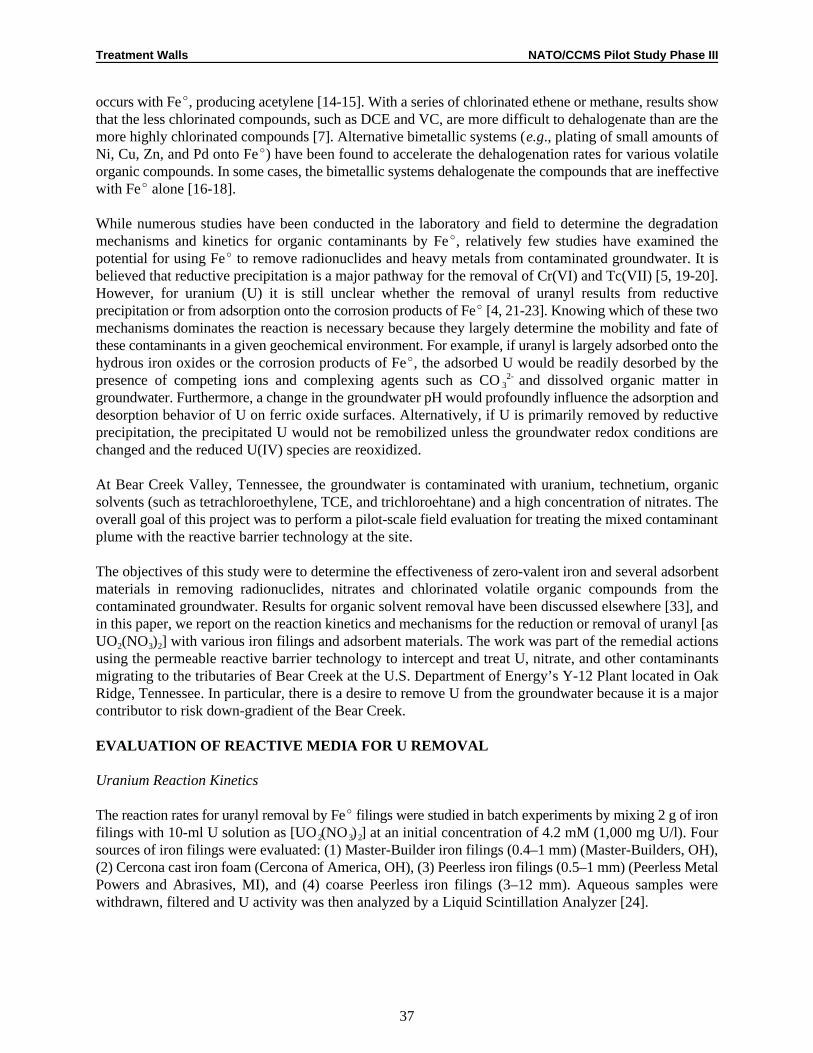
Treatment Walls NATO/CCMS Pilot Study Phase III
37
occurs with FeE, producing acetylene [14-15]. With a series of chlorinated ethene or methane, results showthat the less chlorinated compounds, such as DCE and VC, are more difficult to dehalogenate than are themore highly chlorinated compounds [7]. Alternative bimetallic systems (e.g., plating of small amounts ofNi, Cu, Zn, and Pd onto FeE) have been found to accelerate the dehalogenation rates for various volatileorganic compounds. In some cases, the bimetallic systems dehalogenate the compounds that are ineffectivewith FeE alone [16-18].
While numerous studies have been conducted in the laboratory and field to determine the degradationmechanisms and kinetics for organic contaminants by FeE, relatively few studies have examined thepotential for using FeE to remove radionuclides and heavy metals from contaminated groundwater. It isbelieved that reductive precipitation is a major pathway for the removal of Cr(VI) and Tc(VII) [5, 19-20].However, for uranium (U) it is still unclear whether the removal of uranyl results from reductiveprecipitation or from adsorption onto the corrosion products of FeE [4, 21-23]. Knowing which of these twomechanisms dominates the reaction is necessary because they largely determine the mobility and fate ofthese contaminants in a given geochemical environment. For example, if uranyl is largely adsorbed onto thehydrous iron oxides or the corrosion products of FeE, the adsorbed U would be readily desorbed by thepresence of competing ions and complexing agents such as CO and dissolved organic matter in3
2-
groundwater. Furthermore, a change in the groundwater pH would profoundly influence the adsorption anddesorption behavior of U on ferric oxide surfaces. Alternatively, if U is primarily removed by reductiveprecipitation, the precipitated U would not be remobilized unless the groundwater redox conditions arechanged and the reduced U(IV) species are reoxidized.
At Bear Creek Valley, Tennessee, the groundwater is contaminated with uranium, technetium, organicsolvents (such as tetrachloroethylene, TCE, and trichloroehtane) and a high concentration of nitrates. Theoverall goal of this project was to perform a pilot-scale field evaluation for treating the mixed contaminantplume with the reactive barrier technology at the site.
The objectives of this study were to determine the effectiveness of zero-valent iron and several adsorbentmaterials in removing radionuclides, nitrates and chlorinated volatile organic compounds from thecontaminated groundwater. Results for organic solvent removal have been discussed elsewhere [33], andin this paper, we report on the reaction kinetics and mechanisms for the reduction or removal of uranyl [asUO (NO ) ] with various iron filings and adsorbent materials. The work was part of the remedial actions2 3 2
using the permeable reactive barrier technology to intercept and treat U, nitrate, and other contaminantsmigrating to the tributaries of Bear Creek at the U.S. Department of Energy’s Y-12 Plant located in OakRidge, Tennessee. In particular, there is a desire to remove U from the groundwater because it is a majorcontributor to risk down-gradient of the Bear Creek.
EVALUATION OF REACTIVE MEDIA FOR U REMOVAL
Uranium Reaction Kinetics
The reaction rates for uranyl removal by FeE filings were studied in batch experiments by mixing 2 g of ironfilings with 10-ml U solution as [UO(NO ) ] at an initial concentration of 4.2 mM (1,000 mg U/l). Four2 3 2
sources of iron filings were evaluated: (1) Master-Builder iron filings (0.4–1 mm) (Master-Builders, OH),(2) Cercona cast iron foam (Cercona of America, OH), (3) Peerless iron filings (0.5–1 mm) (Peerless MetalPowers and Abrasives, MI), and (4) coarse Peerless iron filings (3–12 mm). Aqueous samples werewithdrawn, filtered and U activity was then analyzed by a Liquid Scintillation Analyzer [24].
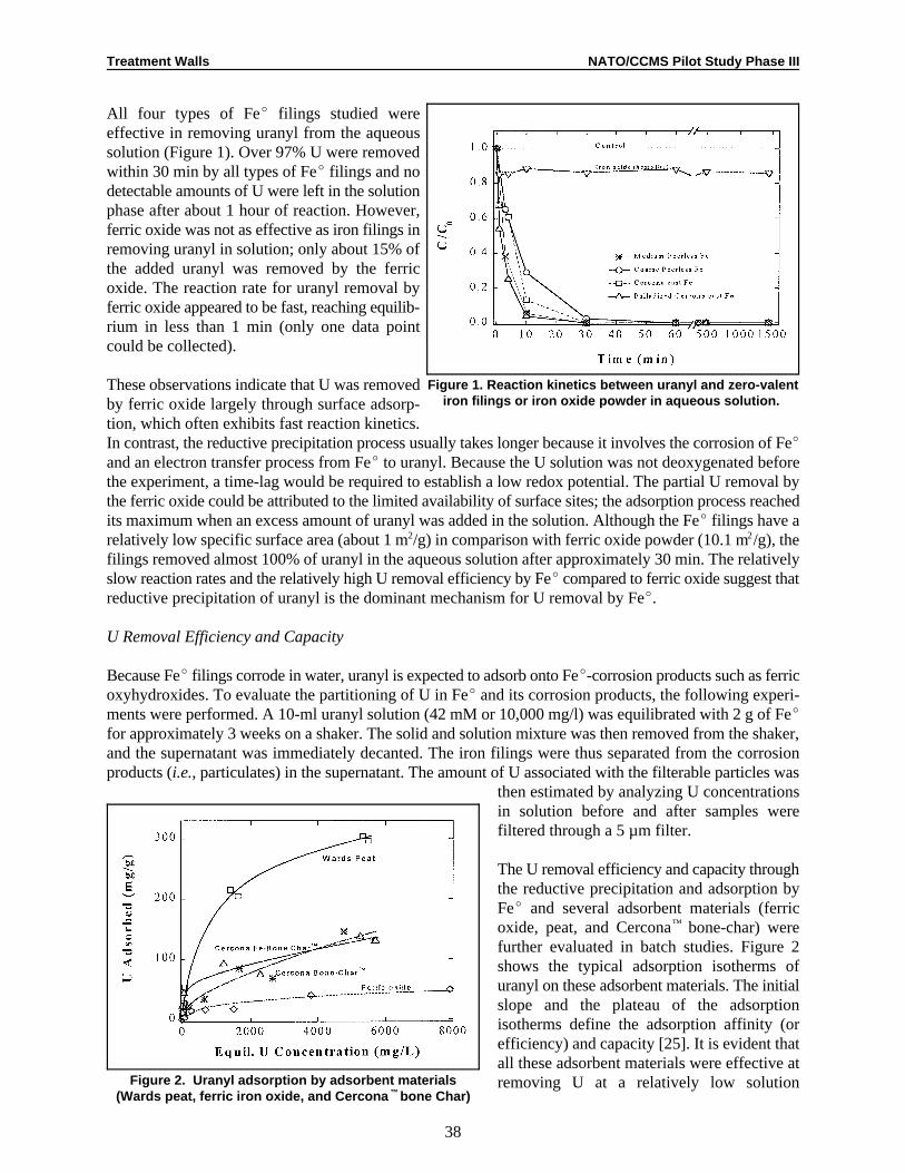
Treatment Walls NATO/CCMS Pilot Study Phase III
38
Figure 1. Reaction kinetics between uranyl and zero-valentiron filings or iron oxide powder in aqueous solution.
Figure 2. Uranyl adsorption by adsorbent materials(Wards peat, ferric iron oxide, and Cercona bone Char)™
All four types of FeE filings studied wereeffective in removing uranyl from the aqueoussolution (Figure 1). Over 97% U were removedwithin 30 min by all types of FeE filings and nodetectable amounts of U were left in the solutionphase after about 1 hour of reaction. However,ferric oxide was not as effective as iron filings inremoving uranyl in solution; only about 15% ofthe added uranyl was removed by the ferricoxide. The reaction rate for uranyl removal byferric oxide appeared to be fast, reaching equilib-rium in less than 1 min (only one data pointcould be collected).
These observations indicate that U was removedby ferric oxide largely through surface adsorp-tion, which often exhibits fast reaction kinetics.In contrast, the reductive precipitation process usually takes longer because it involves the corrosion of FeE
and an electron transfer process from FeE to uranyl. Because the U solution was not deoxygenated beforethe experiment, a time-lag would be required to establish a low redox potential. The partial U removal bythe ferric oxide could be attributed to the limited availability of surface sites; the adsorption process reachedits maximum when an excess amount of uranyl was added in the solution. Although the FeE filings have arelatively low specific surface area (about 1 m/g) in comparison with ferric oxide powder (10.1 m /g), the2 2
filings removed almost 100% of uranyl in the aqueous solution after approximately 30 min. The relativelyslow reaction rates and the relatively high U removal efficiency by FeE compared to ferric oxide suggest thatreductive precipitation of uranyl is the dominant mechanism for U removal by FeE.
U Removal Efficiency and Capacity
Because FeE filings corrode in water, uranyl is expected to adsorb onto FeE-corrosion products such as ferricoxyhydroxides. To evaluate the partitioning of U in FeE and its corrosion products, the following experi-ments were performed. A 10-ml uranyl solution (42 mM or 10,000 mg/l) was equilibrated with 2 g of FeE
for approximately 3 weeks on a shaker. The solid and solution mixture was then removed from the shaker,and the supernatant was immediately decanted. The iron filings were thus separated from the corrosionproducts (i.e., particulates) in the supernatant. The amount of U associated with the filterable particles was
then estimated by analyzing U concentrationsin solution before and after samples werefiltered through a 5 µm filter.
The U removal efficiency and capacity throughthe reductive precipitation and adsorption byFeE and several adsorbent materials (ferricoxide, peat, and Cercona bone-char) were™
further evaluated in batch studies. Figure 2shows the typical adsorption isotherms ofuranyl on these adsorbent materials. The initialslope and the plateau of the adsorptionisotherms define the adsorption affinity (orefficiency) and capacity [25]. It is evident thatall these adsorbent materials were effective atremoving U at a relatively low solution

Treatment Walls NATO/CCMS Pilot Study Phase III
39
Figure 3. U removal by various zero-valent iron filings: Master-Builder (MB) with headspace, MB without headspace,
and Peerless coarse iron filings
concentration (<50 mg U/l). The initial slopes (i.e., the initial partitioning coefficients) ranged from about40 to > 10,000 ml/g, with the Cercona Fe-bone-char being the most effective at a low initial concentration.™
However, the Wards peat exhibited an adsorption capacity that was 2-3 times higher than that of Cercona™
Fe-bone-char and about 5-6 times higher than that of the ferric oxides on a weight basis. As the solution Uconcentration increased, a relatively large percentage of U was left in the solution because of the limitedsorption capacity of the solid materials.
In contrast, reactions between uranyland FeE resulted in almost 100%removal of U in solution as shown inFigure 3. Regardless of the initial Uconcentration in solution (up to 84mM or 20,000 mg/l), no detectableamounts of U were found in solutionafter reaction with FeE. Note thatFigure 2 is plotted against theequilibrium concentration of uranyl insolution, whereas Figure 3 is plottedagainst the initial U concentrationadded because no detectable amountsof U could be found in the equilibriumsolution. Analysis by the phospho-rescence-lifetime instrument gave notonly a high sensitivity for detectinguranyl (on the order of parts pertrillion) but also the valence states of
U because U(IV) does not phosphoresce [26]. In order to determine if the reduced U(IV) species werepresent in the equilibrium solution phase, some selected aqueous samples were also exposed to the air andtreated with peroxide (HO ) and HNO and re-analyzed by the phosphorescence-lifetime instrument. Again,2 2 3
no detectable amount of U was found in the solution after the treatment. These results are thereforeindicative of a reductive precipitation of U by FeE rather than an adsorption process because adsorptionwould have resulted in a partitioning of U in the solution phase. No maximum loading capacity may bedefined for U removal as long as sufficient amounts of FeE are present in the system to maintain a favorablereducing environment. The adsorption process may dominate only when FeE is consumed and the corrosionproducts (Fe-oxyhydroxides) are formed in the system.
We further evaluated the percentage distribution of U in the FeE and its corrosion products in suspensionbecause, if U was largely adsorbed on the corrosion products of FeE, the adsorbed U may be desorbed and/orco-transported with the suspended colloidal particles. Results (Table 1) indicated that only a smallpercentage of U was associated with these suspended particles (or the corrosion products) after shaking for~3 weeks in the batch experiments. The majority of added uranyl was precipitated on the FeE. Additionally,a desorption experiment with 0.1M NaCO indicated that U associated with suspended particles (i.e., the2 3
corrosion products) was readily desorbed (>64%). However, only small amounts of U (<0.21%) in FeE couldbe washed out with the carbonate solution (Table 1). It is known that CO complexes with uranyl to form3
2-
negatively charged U species such as UO(CO ) , which does not adsorb on the negatively charged ferric2 3 22-
oxyhydroxide surfaces at the given pH conditions (pH > 10) [27-28]. The zero point of charge of commonferric oxyhydroxides is in the range of 6-8.5 [29]. Therefore, these results suggest that uranyl, which wasin the initial solution, was converted to less soluble U(IV) species by the FeE. The large percentage ofextracted U from the suspended particulates implies that U was primarily adsorbed in its VI-oxidation stateby the corrosion products, although these corrosion products only constituted a small percentage of the FeE
mass. These observations are consistent with that of Grambow et al. [21], who found that a large percentage
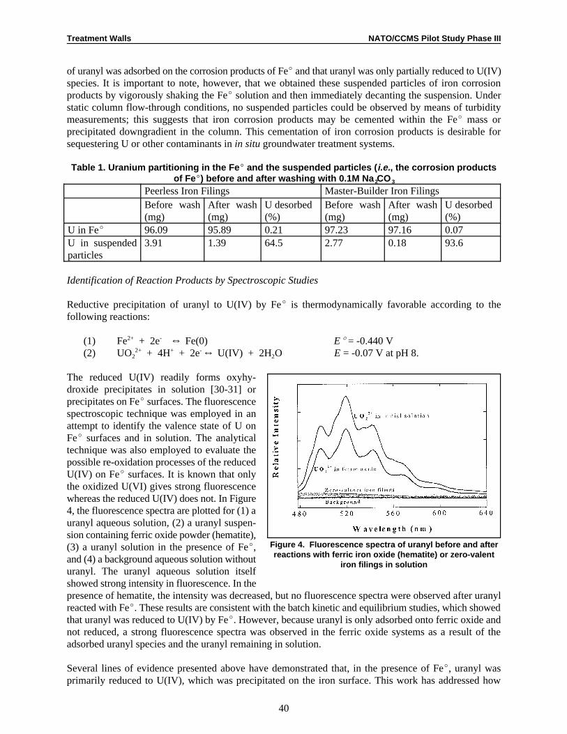
Treatment Walls NATO/CCMS Pilot Study Phase III
40
Figure 4. Fluorescence spectra of uranyl before and afterreactions with ferric iron oxide (hematite) or zero-valent
iron filings in solution
of uranyl was adsorbed on the corrosion products of FeE and that uranyl was only partially reduced to U(IV)species. It is important to note, however, that we obtained these suspended particles of iron corrosionproducts by vigorously shaking the FeE solution and then immediately decanting the suspension. Understatic column flow-through conditions, no suspended particles could be observed by means of turbiditymeasurements; this suggests that iron corrosion products may be cemented within the FeE mass orprecipitated downgradient in the column. This cementation of iron corrosion products is desirable forsequestering U or other contaminants in in situ groundwater treatment systems.
Table 1. Uranium partitioning in the Fe E and the suspended particles ( i.e., the corrosion productsof FeE) before and after washing with 0.1M Na CO2 3
Peerless Iron Filings Master-Builder Iron FilingsBefore wash After wash U desorbed Before wash After wash U desorbed(mg) (mg) (%) (mg) (mg) (%)
U in FeE 96.09 95.89 0.21 97.23 97.16 0.07U in suspended 3.91 1.39 64.5 2.77 0.18 93.6particles
Identification of Reaction Products by Spectroscopic Studies
Reductive precipitation of uranyl to U(IV) by FeE is thermodynamically favorable according to thefollowing reactions:
(1) Fe + 2e ] Fe(0) EE = -0.440 V2+ -
(2) UO + 4H + 2e ] U(IV) + 2H O E = -0.07 V at pH 8.2 22+ + -
The reduced U(IV) readily forms oxyhy-droxide precipitates in solution [30-31] orprecipitates on FeE surfaces. The fluorescencespectroscopic technique was employed in anattempt to identify the valence state of U onFeE surfaces and in solution. The analyticaltechnique was also employed to evaluate thepossible re-oxidation processes of the reducedU(IV) on FeE surfaces. It is known that onlythe oxidized U(VI) gives strong fluorescencewhereas the reduced U(IV) does not. In Figure4, the fluorescence spectra are plotted for (1) auranyl aqueous solution, (2) a uranyl suspen-sion containing ferric oxide powder (hematite),(3) a uranyl solution in the presence of FeE,and (4) a background aqueous solution withouturanyl. The uranyl aqueous solution itselfshowed strong intensity in fluorescence. In thepresence of hematite, the intensity was decreased, but no fluorescence spectra were observed after uranylreacted with FeE. These results are consistent with the batch kinetic and equilibrium studies, which showedthat uranyl was reduced to U(IV) by FeE. However, because uranyl is only adsorbed onto ferric oxide andnot reduced, a strong fluorescence spectra was observed in the ferric oxide systems as a result of theadsorbed uranyl species and the uranyl remaining in solution.
Several lines of evidence presented above have demonstrated that, in the presence of FeE, uranyl wasprimarily reduced to U(IV), which was precipitated on the iron surface. This work has addressed how

Treatment Walls NATO/CCMS Pilot Study Phase III
41
Figure 5. Fluorescence spectra of U on zero-valent ironsurfaces, showing the adsorbed uranyl or the reoxidation
of precipitated U(IV) to U(VI) species
persistent these reduced U species are on theiron surface, especially if they are exposed toatmospheric oxygen. Figure 5 shows thefluorescence spectra of a few solid FeE
samples at different exposure to air afterreacting with uranyl solutions. A strongfluorescence spectrum was observed afteruranyl was reacted with a rusted FeE and thendried in the air for 2 days. By comparison, amuch weaker fluorescence spectrum wasobserved when uranyl reacted with FeE andwas then dried in a Speed-Vac for 4 h. Nofluorescence signal could be identified for thefreshly prepared U- FeE specimen. Theseresults demonstrate that the reduced U(IV)species on FeE surfaces could be re-oxidized.Furthermore, the re-oxidation rate appeared tobe relatively slow (on the order of days) in comparison with its reduction process (on the order of minutes,Figure 1).
Implications for groundwater remediation
Both batch experiments and spectroscopic studies showed that FeE is effective in removing U from waterunder reducing conditions. The major reaction pathway is via reduction of uranyl by FeE to form insolubleU(IV) surface species. Adsorption of uranyl by corrosion products accounts for a small percentage of totaluranyl removal. The overall removal rates are fairly fast, and the half-life of the reaction is on the order ofa few minutes, assuming a pseudo-first order kinetic reaction. Experiments also show that re-oxidation canoccur when reduced U(IV) is exposed to atmospheric oxygen.
These results imply that using iron in a permeable reactive barrier to remove U is feasible for groundwaterremediation. However, U retained by FeE may be reoxidized and remobilized when the precipitated U(IV)on FeE is exposed to atmospheric oxygen. The effect of dissolved oxygen in water on the rate of re-oxidationhas not been determined in this study, but will be included in future work. As long as a reducing conditionis maintained in the permeable reactive barrier by FeE, it is likely that the reduced U(IV) is coprecipitatedand eventually cemented with the FeE corrosion products. Both laboratory and field-scale experiments areunderway to determine the removal efficiency in situ, and to gauge the geochemical influence to suchtechnology. The long-term performance of FeE reactive barriers with respect to its efficiency, byproductformation, and clogging is still a matter of debate [32]. Results of this work have demonstrated that FeE isan effective medium that can be used to remove certain redox-sensitive radionuclides and metals, in additionto its ability to degrade many chlorinated organic compounds.
ACKNOWLEDGMENTS
Cercona Bone-Char materials were supplied by R. Helferich at Cercona of America, Inc. Technical™
assistance by Dr. M. Dickey, X. Yin and assistance on SEM and XRD analyses by Y. Roh and S. Y. Lee aregratefully acknowledged. We thank D. Watson for his helpful comments on the manuscript. This work wassupported by the Subsurface Contaminants Focus Area of Office of Environmental Management, U.S.Department of Energy. Travel support for L. Liang through the UK Environment Agency is gratefullyacknowledged.

Treatment Walls NATO/CCMS Pilot Study Phase III
42
REFERENCES
1. R.W. Gillham, U.S. Patent 5266213, Nov 30, 1993.2. S.H. Shoemaker, J.F. Greiner, R.W. Gillham, in “Assessment of Barrier Containment Technologies”,
R. R. Rumer, J.K. Mitchell (eds.). (1995) Section 11, 301.3. R.W. Gillham, S. F. O’Hannesin, Ground Water 32(6) (1994) 958.4. K.J. Cantrell, D.I. Kaplan, T.W. Wietsma, J. Hazardous Materials 42 (1995) 201.5. R.M. Powell, R.W. Puls, S.K. Hightower, D.A. Sabatini, Environ. Sci. Technol. 29 (8) (1995) 1913.6. L. Liang, J. D. Goodlaxson, in ‘Emerging Technologies in Hazardous Waste Management VII, extended
Abstracts for the special symposium, Atlanta, GA’ (1995a) 46.7. T.L. Johnson, M. M. Scherer, P.G. Tratnyek. Environ. Sci. Technol. 30(8) (1996) 2634.8. American Chemical Society Extended Abstracts of 209th National Meeting, Division of Environmental
Chemistry, Anaheim, CA 35 (1) (1995).9. Emerging Technologies in Hazardous Waste Management VII, extended Abstracts for the special
symposium, Atlanta, GA (1995).10. L.J. Matheson, P. G. Tratnyek, Environm. Sci. Technol 28(12) (1994) 2045. 11. T.M. Vogel, C.S. Criddle, P.L. McCarty, Environ. Sci. Technol. 21(8) (1987) 722.12. T.M. Sivavec, D.P. Horney, in Extended Abstracts of 209th National Meeting. Anaheim, CA. Division
of Environmental Chemistry. 35(1) (1995) 695. 13. L. Liang, J. D. Goodlaxson, N. E. Korte, J. L. Clausen, D. T. Davenport, in Extended Abstracts of 209th
National Meeting. Anaheim, CA. Division of Environmental Chemistry. 35(1) (1995b) 728.14. T.J. Campbell, D.R. Burris, A.L. Roberts, J.R. Wells. Environ. Tox. Chem. 16(4) (1997) 625.15. A.L. Roberts, L.A. Totten, W.A. Arnold, D.R. Burris, T.J. Campbell, Environ. Sci. Technol. 30(8)
(1996) 2654. 16. C. Grittini, M.Malcomson, Q. Fernando, N. E. Korte, Environ. Sci. Technol. 29(11) (1995) 2898.17. L. Liang, N.E. Korte, J.D. Goodlaxson, J. Clausen, Q. Fernando, R. Muftikian, Ground Water
Monitoring and Remediation, Winter (1997a) 122.18. T. M. Sivavec, P.D. Mackenzie, D.P. Horney, S.S. Baghel, Preprint from the 1997 International
Containment Technology Conference, St. Petersburg, FL., Feb 9-12, 1997.19. D.W. Blowes, C.J. Ptacek (1994). ‘System for treating contaminated groundwater,’ U.S. Patent No.
5,362,394.20. L. Liang, B. Gu, X. Yin. Separations Technol. 6 (1996) 111-122.21. Grambow, B.; Smailos, E.; Greckeis, H.; Muller, R.; Hentschel, H. Radiochim. Acta 1996, 74, 149-154.22. Wersin, P.; Hochella Jr., M. F.; Persson, P.; Redden, G.; Leckie, J. O.; Harris, D. W. Geochim.
Cosmochim. Acta 1994, 58, 2829-2843.23. Bostick, W. D.; Jarabek, R. J.; Fiedor, J. N.; Farrell, J.; Helferich, R. Proceedings of the 1997
International Containment Technology Conference and Exhibition. St. Petersburg, FL 1997, 767-773.
24. Gu, B.; Dowlen, K. E.; Liang, L.; Clausen, J. L. Sep. Technol. 1996, 6, 123-132. 25. Gu, B.; Schmitt, J.; Chen, Z.; Liang, L.; McCarthy, J. F. Environ. Sci. Technol. 1994, 28, 38-46.26. Dai, S.; Metcalf, D. H.; Del Cul, G. D.; Toth, L. M. Inorg. Chem. 1996, 35, 7786-7790. 27. Hsi, C. K. D.; Langmuir, D. Geochim. Cosmochim. Acta 1985, 49, 1931-1941.28. Ho, C. H.; Miller, N. H. J. Coll. Interf. Sci. 1986, 110, 165. 29. Sposito, G. The surface chemistry of soils; Oxford University Press, New York 1984. 30. Baes, C. F.; Mesmer, R. E. The Hydrolysis of Cations; John Wiley & Sons: New York, 1976. 31. Dai, S.; Toth, L. M.; Del Cul, G. D.; Metcalf, D. H. J. Phys. Chem. 1996, 100, 220. 32. Liang, L.; Jacobs, G. K.; Gu, B. Coll. Surf. 1997, (in review).33. B. Gu, L. Liang, M.J. Dickey, X. Yin and P. Cameron. Preprint of extended abstract for RTDF
permeable reactive barriers Action Tam Meeting, Virginia Beach, VA. Sept. 18-19, 1997.

Treatment Walls NATO/CCMS Pilot Study Phase III
43
Discussion
Wolfgang Wüst asked whether Liang observed a maximum capacity for sorption of uranium. He noted thathe did not see a problem with leaving uranium in an iron reactor because it is very anoxic and uranium willremain reduced unless conditions become oxidizing and mobilize the uranium. Liang indicated that leavinguranium in the reactor is a different issue from leaving iron in situ when used for treating organic solventsbecause of the environmental implications. She said that the experiments that were conducted examined theworst-case scenario. In column flow-through experiments, no suspended solids were noted.
Timothy Vogel asked whether nitrate was transformed mainly to ammonia or whether it was converted tonitrogen gas as well. Liang responded that the nitrate was mainly transformed to nitrite because reductionto nitrogen takes longer. Wüst added that he did not find nitrite in his experiments. We all agree that thereactive media determine the by-products of the reaction.
Treatment Walls NATO/CCMS Pilot Study Phase III
TNO/MEP, P.O. Box 342, 7300 AH Apeldoorn, The Netherlands, tel: 31/55-5493-380, fax: 31/55-5493-410, e-mail:1
44
Bioprocesses in Treatment Walls: Bioscreens
Huub H. M. Rijnaarts1
Abstract
The feasibility of intrinsic and enhanced bioremediation approaches for 16 contaminated sites in theNetherlands are discussed. At least five out of 10 chlorinated solvent sites, natural attenuation can be usedas one of the tools to prevent further dispersion of the plume. At two sites stimulation of the intrinsicdechlorination processes in a bioactive zone is required, and pilot field tests are currently under way. In threesulphate-reducing/methanogenic aquifers contaminated with aromatic compounds, natural anaerobicdegradation of the risk-determining benzene was demonstrated not to occur spontaneously by microcosmstudies. Benzene biodegradation could be initiated by feeding small amounts of oxygen (in all samples) ornitrate (only in one sample). Investigations at two locations contaminated with hexachlorocyclohexanes(HCHs) indicated significant intrinsic bioattenuation of HCHs under very low field-redox conditions, andof the HCH-degradation products chlorophenol and benzene under sulphate/iron reducing conditions.Biostimulated zones remain required to complete the degradation of HCH and the degradation productmonochlorobenzene.
INTRODUCTION
The ideas concerning best approaches for remediation of polluted soil and groundwater are rapidly changing.A few years ago many engineers and regulators considered contaminated aquifers as biologically inactivesystems that could only be remediated by very drastic and expensive methods like soil vapor extraction orlarge scale pump-and-treat. Nowadays, one has become aware that the natural microbial population in soiland groundwater react actively when confronted with pollution, and thus offer new and better ways toprotect groundwater resources at acceptable costs.
Often, natural biodegradation processes can convert large amounts of contaminants without any externalstimulus. Sometimes, the natural processes can completely degrade or immobilize pollutants during theirdown-gradient transport. When sufficient time and space is available, an intrinsic remediation approach canin principal be completely protective for man and surrounding ecosystems. At other sites, the naturalbiodegradation processes need to be enhanced in order to obtain a sufficient risk reduction and groundwaterprotection. Such a stimulation can be performed in a bioactive zone or bioscreen. In such a zone, theautochthonous bacteria are supplied with the appropriate electron donors, acceptors or nutrients. At somesites, the microbial population is not yet fully adapted to the most optimal biodegradation process. In sucha case bioaugmentation of the bioscreen may be a solution. Intrinsic remediation, when necessary combinedwith bioscreens, is becoming the new approach to deal with large and complex contaminated sites.
Natural and enhanced attenuation as a risk based solution for contaminated soil and aquifers is currentlybeing investigated at various sites in the Netherlands. A number of the 16 cases investigated by TNO willbe discussed below.

Treatment Walls NATO/CCMS Pilot Study Phase III
45
RESULTS AND DISCUSSION
Chlorinated Solvents
At the Rademarkt site (Groningen, The Netherlands) contaminated with perchloroethylene (PCE) andtrichloroethylene (TCE), mixed redox conditions control the intrinsic biodegradation processes. In amethanogenic/sulfate reducing zone a complete reductive dechlorination reaction via vinyl chloride toethene and ethane occurs. However, the transformation rates of vinyl chloride observed in the field (and inthe laboratory) are too slow to prevent migration of this hazardous compound to areas to be protected. Thelow amounts of DOC (< 10 mg/l) indicate a lack of sufficient amounts of electron donor naturally present.Laboratory experiments identified that a mixture of electron-donors is most suitable to enhance the in situreductive dechlorination. An in situ pilot test with an anaerobic activated zone designed for completereductive dechlorination is planned this fall. In another flow direction in the field, the redox conditionchanges from methanogenic/sulfate reducing to oxic conditions. In the reduced part, PCE and TCE aretransformed to cis-1,2-dichloroethylene (DCE) and vinyl chloride (VC), which both disappear after enteringthe oxic zone. Probably, these compounds are removed by intrinsic oxidation. Hence, in this flow direction,a complete sequential degradation of the chlorinated compounds is achieved.
At another PCE/TCE site in Maassluis, the contaminated aquifer contains high concentrations of organiccarbon (up to 700 mg/l DOC). Here, complete reductive dechlorination is observed. Most likely, this is aresult of the high amounts of intrinsic electron donors and a well-adapted autochthonous microbial popula-tion.
The results of the characterization of redox conditions and intrinsic biodegradation at 10 chlorinated solventsites will be presented. For at least five of these sites studied, intrinsic remediation is an important part inan approach to effectively control the risks. At two sites at least, in situ biodegradation needs to bestimulated in in situ activated zones to protect down stream areas.
Intrinsic chlorinated solvent remediation is further investigated by testing electron donors and measuringin situ hydrogen pressures in the field and in laboratory microcosms. Thus a further insight into mechanismsinvolved will be obtained.
At present, new technologies are being developed by TNO for application in bioscreens and remediatingchlorinated solvent hot spots and chlorinated solvents in low-permeable soils and subsurface layers.Combination of electro-reclamation techniques and biological methods appear to bring new solutions in thenear future.
Aromatic and Oil-Related Hydrocarbons
Aromatic compounds are often the risk-controlling compounds at oil and gas production sites, and at sitesof coating and nutrition industries. At three sites in the north part of The Netherlands, deep anaerobicaquifers contaminated with benzene, toluene, ethylbenzene or xylenes (BTEX) have been investigated.Under the existing sulfate-reducing conditions, the intrinsic biodegradation of toluene and ethylbenzenecould be demonstrated in the field and in microcosm studies. Benzene biodegradation could not beevidenced with the field data. Laboratory microcosm studies with five different sediment samples wereperformed. For each sample a series of comparable triplicate microcosms were incubated; in total about 300microcosms were used. The results demonstrate thus far (200 days of incubation) that spontaneous intrinsicanaerobic benzene biodegradation does not occur in these sediment and groundwater samples.
Microcosm method development studies indicated that special care is required to prevent artifacts: “apparentintrinsic anaerobic” benzene biodegradation could be demonstrated to originate from low (often not

Treatment Walls NATO/CCMS Pilot Study Phase III
46
measurable) amounts of oxygen introduced into the systems, when inappropriate materials and techniqueswere used.
Microcosms were also used to investigate possibilities to stimulate biodegradation of benzene and BTEXcompounds. Especially, addition of nitrate and low amounts of oxygen to the anaerobic samples was studied.In one out of the five series of sediment-microcosms, nitrate-reducing benzene biodegradation appeared tooccur after lag-times greater than 100 days. In addition, anaerobic benzene degradation could be initiatedin all samples by spiking low amounts of oxygen. Further investigations are underway to elucidatemechanisms and quantify remediation process parameters. The results are used for designing pilotdemonstration tests to be performed this spring/summer.
At an oil refinery site in the Rotterdam Harbor area, an aerobic reactive-trench bioscreen is tested formanaging a plume of the dissolved fraction of a mineral oil contamination (80% of the compounds belongto the C6 - C12 fraction). Bench scale experiments are currently performed to establish: i) optimal grain-sizeand packing density for the porous media used in the trench; and ii) optimal oxygen supply rates tosufficiently initiate aliphatic hydrocarbon biodegradation and to minimize clogging with iron(III)oxides.
Chlorinated Pesticides
HCH isomers are important pollutants introduced by the production of lindane (gamma HCH). At two sites,intrinsic anaerobic biodegradation of HCH and corresponding degradation-intermediates (benzene andmonochlorobenzene) is currently being investigated. At one site, natural biodegradation processes appearto completely degrade all compounds except the monochlorobenzene; possibly some biostimulation maybe required at the downstream end of the plume. At the other site, interception of the HCH/chloro-benzene/benzene plume is required. A bioactivated zone as an alternative to conventional large scale pump-and-treat is currently being investigated. At present, laboratory process research aimed at developing acombination of anaerobic-microaerophilic in situ stimulation in such a bioactivated zone is being performed.The results indicate good prospects for further development and pilot scale demonstration.
Guidelines for Application of Natural Attenuation or Bioscreens
Dutch and Nicole-supported guidelines for assessing the feasibility of natural attenuation approaches forvarious contaminant situations are currently under development, making use of already existing protocols(USA) and taking Dutch/European specific conditions, knowledge and regulatory constraints into account.These guidelines are to become tiered decision tools. In the first steps, a minimum of data is required foran initial feasibility screening, thus saving costs. At higher tiers, data requirements are designed to addressnatural degradation under various redox-situations (including sequential redox conditions) that often occurin European sedimentary regions.
CONCLUSION
Intrinsic and enhanced in situ bioremediation approaches become more and more accepted as appropriatecost-effective solutions for aquifers and soils contaminated with organic chemicals. These techniques stillneed to be further developed and demonstrated and could also be expanded to control and remediatemixtures of organic and inorganic (heavy metal) pollutants.
Discussion
Hexachlorocyclohexanes can be degraded using zero-valent iron and without producing benzene as a by-product. Zero-valent iron may be an appropriate reactive material for these types of compounds as long asthe mass-balance considers monochlorinated benzene.

Treatment Walls NATO/CCMS Pilot Study Phase III
47
Because there is no natural nitrate at the site, anaerobic benzene degradation was stimulated by introducingnitrate. Even though The Netherlands has a 50 mg/l nitrate drinking water standard, the introduction ofnitrate did not pose a problem because concentrations in the stimulated system ranged from only 10-20 mg/l.

Treatment Walls NATO/CCMS Pilot Study Phase III
This paper was prepared from a transcript of Dr. Vogel’s presentation.1
Rhodia Eco Services\ATE, 17 rue Périgord, 69330 Meyzieu, France; tel: 33/4-7245-0425; Fax: 33/4-7804-2430; e-2
mail: [email protected].
48
Figure 1. Reactions
Reaction rates Activation energy, sterichinderance, diffusionlimits
Compounds degraded Electrophilicity,hydrogenation
Corrosion of material Selective reactivity,protection, pretreatment
Metal inactivation Chemical reactivity,redox changes —electron sources
Figure 2. Problems and Solutions
Novel Catalyses for Reactive Barriers1
Timothy M. Vogel2
The presentation that we will make today is a combination of several different presentations, not necessarilythose planned for today. But the point is simply to talk about different types of material that might be ableto catalyze or to react with compounds of interest in barriers and in wall systems, so we can target a numberof different reactions (Figure 1), and we’ll use some information that has been collected in other laboratoriesand with participants, including Nada Assaf-Anid at the University of Manhattan, Pedro Alvarez from theUniversity of Iowa, and Larry Nies atPurdue University, who all havecontributed in some or the other to thedata that we will present today.
There are basically two differentconcepts for the remediation of ground-water contamination: (1) Methods basedon transfer and concentration of thecontaminants based on activated carbon—activated carbon even in a wall is nota reactive wall but an adsorptionwall—and more innovative methodssuch as mobilization of contaminantswith surfactants or in situ absorption barriers—but these methods all produce secondary waste streams thathave to be treated separately. (2) Destructive methods—such as thermal, oxidative, biological, or catalyticdehalogenation—that are shown in the laboratory to work effectively.
What we’d like to do is to talk about these reactive systems from two points of view: what kind of reactionswe would like to observe, and what reactions we would not like to observe. The example is with thechlorinated alkenes, where a lot of individuals do not like to see the presence of vinyl chloride. What we’lltalk about is ways to catalyze some of these reactions and to avoid certain by-products.
Our approach is to look at the different problemsthat have been associated with literature reports oncatalyzed reactions and to try to identify ways toanswer these questions. Today one of our goals isto, in a sense, initiate some discussion, because weare going to talk about some things that have notnecessarily been brought to a scientific, criticalreview, nor applied in full-scale processes, so anycomments that you have would be gratefullyreceived.
We looked at reaction rates (Figure 2), and thequestion often asked is, how we can do reactionsfaster. In a talk presented yesterday, there was a

Treatment Walls NATO/CCMS Pilot Study Phase III
49
Figure 3. Simplified electron flow
comparison between zero-valent iron and biological reactions, where the rates were much faster with thezero valent. And then just recently, we had another on the use of bio-screens, so there is a question aboutreaction rate that has to be considered with cost—we’re not going to talk about cost—we’re going to talkabout what we can to increase reaction rates. So either we try to change the activation energy of the system,or in the case where there is some kind of steric hindrance—where the molecules cannot come in contactwith the reactive surface—or in the same respect diffusion limits between the molecules in the bulk solutionand the site of reactivity. These are ways to address the reaction rates and maybe improve them.
Other questions are related to the compounds that are degraded. Many compounds are degraded by existingsystems, but are degraded at rates that are not acceptable, therefore some people say these compounds arenot degraded by a particular system. For example, some people say iron cannot degrade a certain chlorinatedcompound, when in fact it’s more the rate that is not acceptable, not whether it can degrade or not degrade.We’d like to separate the issue of the possibility of a degradation occurring from an unacceptable rate. Thus,we want to examine the kinds of mechanisms and how they affect these dechlorinations or reductions. Andfinally, there are issues about the lifetime of the material, and how it’s affected, and how you can engineersupport material and different catalyst systems, such that the lifetime is long enough for the application.
In addition, we will discuss some biological aspects and using organisms coupled with other systems likeiron to deal with problems that result from the applications of catalysts.
The general schematic is a cyclic system (Figure 3)in which an electron comes from some source, istransferred to the molecule that is the pollutant, thepollutant is reduced by that reaction, and the sourceis then regenerated (or maybe not) (Assaf-Anid etal.). There are two ways of looking at this: One isbased on thermodynamics, and thermodynamicsare (for those who are not aware of these systems)the pressures pushing the system around—theforce. But then, there is also the question about thekinetics, the rates. You can have a large force, butif you have a small rate, it will be slow. Take ahydraulic dam. You can have a lot of water behinda hydraulic dam, but if the hole is small, not much water will go through it, so we need to separateconceptually thermodynamic data from kinetic data. The thermodynamic possibility is necessary, but itdoesn’t provide you with a real process that you can apply if the kinetics are unacceptably slow.
If we look at the thermodynamics of different systems, we can see in Table 1 (taken from several literaturestudies) that there are measures of different redox couples that are used to determine whether thethermodynamics of a system is favorable not. This is the redox couple between the oxidized and reducedphases of these compounds. Some of the data are pretty standard, for example water—the oxygen/watercouple. This provides you with some information about the potential energy—how high the water is behindthe dam—but it does not tell you anything about the rate at which these reactions will go. These are justpotential electron donors in systems, and those in Figure 4 are ones from biological systems based on a 1987review (Vogel et al., ES&T) concerning these types of catalysts.
Table 1. Standard potentials (EE) of biologically relevant electron donors or reductants
Reductants EE (volts)
Vitamin B -0.59 to -0.812
Co(I) tetraphenylporphin -0.56

Treatment Walls NATO/CCMS Pilot Study Phase III
Reductants EE (volts)
50
Ferrodoxin (reduced) -0.43
H -0.422
Cr(III) -0.41
NADH + H -0.32+
Cytochrome P450 -0.30(unactivated)
Glutathione (reduced) -0.23
Cytochrome P450 -0.17(activated)
Fe (II) deuteroporphin IX 0.00
Ubiquinone (reduced) 0.10
Cytochrome c (+2) 0.22
Fe(II) 0.77
H O 0.822
What is of interest is the effect that the complex has on the metal. If you talk about iron, or oxidized iron,and there is some work with iron porphyrins, the important aspect is that the term, “iron reactive barriers,”for example, is uninformative because it’s necessary to consider whether it’s zero valent iron; whether theiron is complexed in some form or the other; or what the iron is doing.
Table 2 shows redox couples between Fe and Fe in different complexes or the different ligands. Redox3+ 2+
energy varies for the same iron couple, based upon the way that it’s complexed by the organic: the potentialfor reduction or oxidation in these systems varies with the ligand. There is also some cobalt data in the table.A metal is not in an isolated situation, but has certain complexes associated with it that may have an effecton the thermodynamics.
Table 2. Standard reduction potential of Fe and Co to the respective bivalent ions3+ 3+
Ligand EE Fe (+3/+2), V EE Co (+3/+2), V
1,10 phenanthroline +1.20
3 bipyridin +0.95 +0.31
water +0.77 +1.88
glycine -+0.4 +0.15
6 NH +0.37 +0.113
6 (CN)G +0.36 -0.80
cytochrome c +0.25
meso-tetrakis (N-methyl-pyridil) porphin +0.17
EDTA +0.13 +0.374-
rubredoxin -0.05
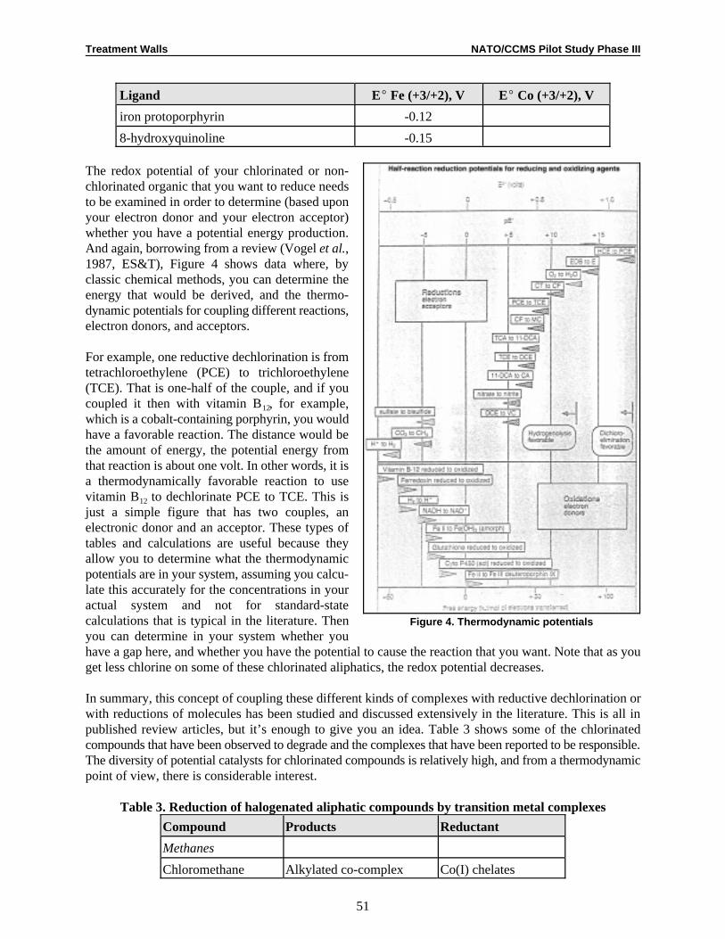
Treatment Walls NATO/CCMS Pilot Study Phase III
Ligand EE Fe (+3/+2), V EE Co (+3/+2), V
51
Figure 4. Thermodynamic potentials
iron protoporphyrin -0.12
8-hydroxyquinoline -0.15
The redox potential of your chlorinated or non-chlorinated organic that you want to reduce needsto be examined in order to determine (based uponyour electron donor and your electron acceptor)whether you have a potential energy production.And again, borrowing from a review (Vogel et al.,1987, ES&T), Figure 4 shows data where, byclassic chemical methods, you can determine theenergy that would be derived, and the thermo-dynamic potentials for coupling different reactions,electron donors, and acceptors.
For example, one reductive dechlorination is fromtetrachloroethylene (PCE) to trichloroethylene(TCE). That is one-half of the couple, and if youcoupled it then with vitamin B, for example,12
which is a cobalt-containing porphyrin, you wouldhave a favorable reaction. The distance would bethe amount of energy, the potential energy fromthat reaction is about one volt. In other words, it isa thermodynamically favorable reaction to usevitamin B to dechlorinate PCE to TCE. This is12
just a simple figure that has two couples, anelectronic donor and an acceptor. These types oftables and calculations are useful because theyallow you to determine what the thermodynamicpotentials are in your system, assuming you calcu-late this accurately for the concentrations in youractual system and not for standard-statecalculations that is typical in the literature. Thenyou can determine in your system whether youhave a gap here, and whether you have the potential to cause the reaction that you want. Note that as youget less chlorine on some of these chlorinated aliphatics, the redox potential decreases.
In summary, this concept of coupling these different kinds of complexes with reductive dechlorination orwith reductions of molecules has been studied and discussed extensively in the literature. This is all inpublished review articles, but it’s enough to give you an idea. Table 3 shows some of the chlorinatedcompounds that have been observed to degrade and the complexes that have been reported to be responsible.The diversity of potential catalysts for chlorinated compounds is relatively high, and from a thermodynamicpoint of view, there is considerable interest.
Table 3. Reduction of halogenated aliphatic compounds by transition metal complexes
Compound Products Reductant
Methanes
Chloromethane Alkylated co-complex Co(I) chelates

Treatment Walls NATO/CCMS Pilot Study Phase III
Compound Products Reductant
52
Dichloromethane Methane Cr(II) SOB -Co(III)12
4
Cl-alkylated B 12
(methylcobalamine)
Trichloromethane Methane Cr(II)SOFe(II)P
Dichloromethane Fe(II)PCl-alkylated B B -Co(III)12
4
Dichloromethane
12
Tetrachloromethane Methane Cr(II)SOChloroform Fe(II)PCl-alkylated B B -Co(III)12
4
12
Bromomethane Methane Cr(II)SOAlkylated co-complex Co(I)-complex
4
Dibromomethane Methane, ethene Fe(II)P
Tribromomethane Br-alkylated B B -Co(III)2 12 12
Ethanes
Chloroethane Alkylated co-complex Co(I)-complex
1,1-Dichloroethane Ethane, ethanol Cr(II)SO4
1,1,1-Trichloroethane Ethane, ethanol, ethene, Cr(II)SOchloroethane1,1-Dichloroethane Fe(II)1,1-Dichloroethane Fe(II)P
4
Hexachloroethane Tetrachloroethene Fe(II)PTetrachloroethene Cr(II)SO4
Bromoethane Ethane Ni(I)
1,1-Dibromoethane Ethane, ethanol Cr(II)SO4
1,2-Dibromoethane Ethene Fe(II)Ethene Fe(II)P
Propanes
1-Chloropropane Alkylated co-complex Co(I)-complex
1,1-Dichloropropane Propane, propanol, propene Cr(II)SO4
1-Bromopropane Alkylated co-complex Co(I)-complex
1,2-Dibromo-3- Propene, allyl chloride Cr(II)SOchloropropane
4
Note: The homolytic cleavage of cobalt-carbon bonds requires 15-30 kcal/mol and can occur at relatively low temperatures.
Figure 5 shows an example where a carbon tetrachloride (CT) is dechlorinated by cobalt in solution tochloroform (CF) over a period of about eight hours. When that cobalt was placed into a porphyrin (Figure6), you see that the reaction rate changes drastically and you have dechlorination within about an hour(Figure 7 is an example of a porphyrin).
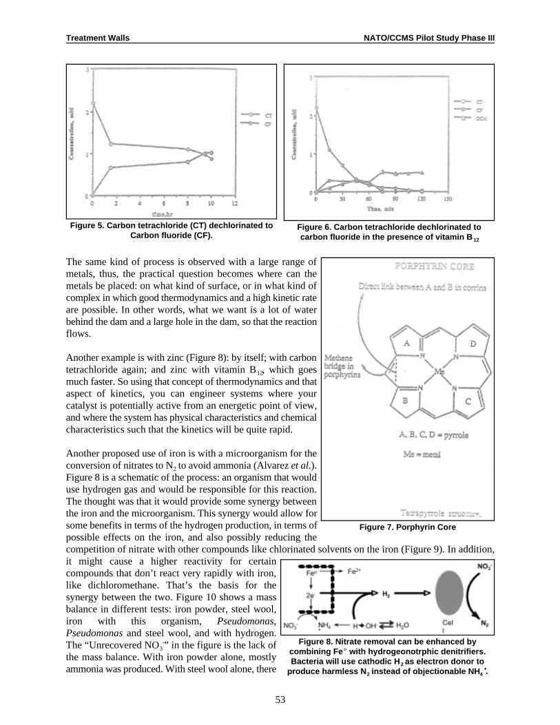
Treatment Walls NATO/CCMS Pilot Study Phase III
53
Figure 5. Carbon tetrachloride (CT) dechlorinated toCarbon fluoride (CF).
Figure 6. Carbon tetrachloride dechlorinated tocarbon fluoride in the presence of vitamin B 12
Figure 7. Porphyrin Core
Figure 8. Nitrate removal can be enhanced bycombining Fe E with hydrogeonotrphic denitrifiers.Bacteria will use cathodic H as electron donor to2
produce harmless N instead of objectionable NH .2 4+
The same kind of process is observed with a large range ofmetals, thus, the practical question becomes where can themetals be placed: on what kind of surface, or in what kind ofcomplex in which good thermodynamics and a high kinetic rateare possible. In other words, what we want is a lot of waterbehind the dam and a large hole in the dam, so that the reactionflows.
Another example is with zinc (Figure 8): by itself; with carbontetrachloride again; and zinc with vitamin B, which goes12
much faster. So using that concept of thermodynamics and thataspect of kinetics, you can engineer systems where yourcatalyst is potentially active from an energetic point of view,and where the system has physical characteristics and chemicalcharacteristics such that the kinetics will be quite rapid.
Another proposed use of iron is with a microorganism for theconversion of nitrates to N to avoid ammonia (Alvarez et al.).2
Figure 8 is a schematic of the process: an organism that woulduse hydrogen gas and would be responsible for this reaction.The thought was that it would provide some synergy betweenthe iron and the microorganism. This synergy would allow forsome benefits in terms of the hydrogen production, in terms ofpossible effects on the iron, and also possibly reducing thecompetition of nitrate with other compounds like chlorinated solvents on the iron (Figure 9). In addition,it might cause a higher reactivity for certaincompounds that don’t react very rapidly with iron,like dichloromethane. That’s the basis for thesynergy between the two. Figure 10 shows a massbalance in different tests: iron powder, steel wool,iron with this organism, Pseudomonas,Pseudomonas and steel wool, and with hydrogen.The “Unrecovered NO” in the figure is the lack of3
-
the mass balance. With iron powder alone, mostlyammonia was produced. With steel wool alone, there

Treatment Walls NATO/CCMS Pilot Study Phase III
54
• eE corrosion rapidly induces anoxic conditions.
• Bacteria may remove passivating H layer from FeE2
surface, increasing FeE reactivity. Use of H2
increases e flow from FeE (cathodic depolarization).-
• Removal of inhibitory products by FeE enhancesbacterial participation in cleanup process (e.g., NO 2
-
reduction by FeE; metals precipitation due to high pHcaused by FeE corrosion).
• Bacteria could remove pollutants that FeE cannot(e.g., dichloromethane).
Figure 9. Basis of Synergism for Fe E + Bacteria
was considerable un-reacted nitrate and ammonia.And in the presence of the microorganism,considerable amounts of the NO were measured in2
these mass balances.
Figure 10. Mass balances
Discussion
In response to a question from Resat Apak, Vogel indicated that some metal chelates used as catalysts areinside membranes. They are trapped in a system that allows the transfer of the chlorinated compound, butkeeps the solubilized porphyrins in membrane systems. Vogel indicated that there are several techniquesdocumented in the literature to re-oxidize the cobalt(II)EDTA to cobalt(III)EDTA, including the use ofelectron donors, solid catalysts, and chemical reductants.
Wolfgang Wüst asked whether any column experiments were done before conducting the field work,because his experience has shown that if catalysts are used, iron hydroxides or other precipitates inhibit thediffusion (and thus reactivity) of EDTA. Schüth said that he was currently running laboratory experimentsin which several thousand pore volumes have been exchanged with groundwater. He has not observed muchprecipitation in these experiments because the pH was lowered, not raised. However, microbial growth didpose a problem for mass transfer due to diffusion.
Liyuan Liang asked whether and how much hydrogen was introduced into the system. Vogel indicated thathydrogen had been introduced in the laboratory, and the amount was calculated by stoichiometry. In thecolumn and laboratory experiments, hydrogen gas was bubbled through the water to create hydrogen-saturated water. However, Vogel cautioned that this approach may not work in the field.
Paul Bardos observed that many of the projects that were discussed in the treatment wall session involvedhighly engineered solutions in terms of emplacing walls and improving the reactive matrix. He asked if theadvantages of these improvements were actually worth the increased costs, given that a trench with ironfilings treats groundwater reasonably well. Vogel responded that iron filings cannot treat all contaminants,nor is there any other existing PRB suited for all contaminants and subsurface environments. Co-contaminants can cause problems, and some contaminants are less reactive than others. The contaminantsthat cannot be treated by iron walls must be determined, and inexpensive reactive materials must be foundto treat them.
Noting that the cost of iron filings for an iron wall accounts for a significant proportion of the constructioncosts, Bob Siegrist asked how the use of a more expensive catalyzed metal such as palladium could be cost-effective when compared to pump-and-treat methods. Vogel responded that although palladium costs more
Treatment Walls NATO/CCMS Pilot Study Phase III
55
than iron, the reactivity of palladium is also greater, so it could still be more cost effective because you donot need as much material. Wüst noted that his tests have indicated that the cost of using 0.1 percentpalladium (the optimum amount) was approximately the same as iron, but the reactivity of the palladiumwas much greater. He expressed concern, however, that the palladium could be mobilized under certainconditions and contaminate the groundwater.
Harry Whittaker noted that there has been a lot of discussion thus far on reductive dehalogenation barriersand asked whether oxidative dehalogenation barriers are being developed. Vogel indicated that techniquesfor oxidative dehalogenation barriers have been patented recently, including systems involving Fenton’sagent.

Treatment Walls NATO/CCMS Pilot Study Phase III
IMES GmbH, Kocherhof 4, 88239 Wangen, Germany, tel: +497528 97130, Fax: +49752897131, e-mail:1
Applied Geology, University of Tobingen, Sigwartstr. 10, 72076 Tubingen, Germany, tel: +49 7071 297 5429, Fax:2
+497071 5059, e-mail: [email protected]
56
Full-Scale ProjectsFunnel-and-Gate Systems for In Situ Treatment of Contaminated
Groundwater at Former Manufactured Gas Plant Sites
Hermann Schad and Peter Grathwohl1 2
Introduction
Groundwater contamination by polycyclic and monocyclic aromatic hydrocarbons (PAH and BTEX) istypical for many former manufactured gas plant sites. Most of the PAHs are very persistent in the subsurfaceenvironment—they are still present in high concentrations many decades after the contamination occurred,and they cannot be removed from the subsurface within a reasonable time period by pump-and-treat. Thispersistence above all is caused by slow dissolution kinetics of the compounds from non-aqueous phaseliquids, slow diffusion of the contaminants from low permeability zones (that have accumulated thepollutants over decades) or resistant adsorption of the contaminants by the aquifer material.
Fast remediation of such contaminations is only possible by excavating the contaminated soil. This,however, can only be applied at shallow sites and is still expensive because of the high disposal or treatmentcosts of the contaminated material. Also the location and extent of the subsurface contamination has to beknown in detail, which is not feasible at large and abandoned industrial sites. Thus, new alternativeapproaches for in situ groundwater remediation have to be developed. Since the goal of remediation ingeneral is the protection of groundwater resources downgradient from a contaminated area, in situ treatmentmay be focused on the plume rather than on the source. This can be achieved using the concept of in situpassive treatment systems, which in general are built perpendicular to the flow direction (e.g., Teutsch etal., 1996). The technical implementation is either in the form of a continuous permeable wall or as a funnel-and-gate system. In both cases no active pumping is required to move the groundwater through the treatmentzone. Within the reactive zone the pollutants are either degraded, sorbed or precipitated through biotic orabiotic processes.
In this paper, we present an example for a funnel-and-gate system, which is currently being planned for thelong-term remediation of the former manufactured gas plant site of the city of Karlsruhe in southernGermany.
Site Characterization
The site is located within the municipal area of the city of Karlsruhe and covers approximately 100,000 m .2
Site investigation programs were completed in 1996 (Trischler and Partner, 1996) with the recommendationfor funnel-and-gate as the most favorable remediation technique for that site. The latter was based on afeasibility study (IMES, 1996), in which the general and site specific advantages of passive in situ treatmentwere discussed and evaluated technically and economically.
The geological and hydrogeological situation at the site may be classified as typical for the upper Rhinevalley. The aquifer has a mean thickness of about 12 m and consists of mostly sandy gravel, which is

Treatment Walls NATO/CCMS Pilot Study Phase III
57
Figure 1. Site map showing the PAH plume and the location of the funnel-and-gate system
underlain by a clay layer at a depth of 15 m below surface. Groundwater drainage is dominated by the Rhineriver northwest of the site. The mean groundwater flow direction therefore is from southeast to northwest(Figure 1). The contamination of the site is dominated by PAHs with acenaphthene being the highestconcentrated compound of the plume extending about 400 m down gradient from the site. Severalinfiltration hot spots of non-aqueous phase (NAPLs) liquids were located within the saturated zone at thesite. PAH concentrations of the soil at many places exceed 10 g/kg. Altogether approximately 55,000 mor3
100,000 tons of soil (within the saturated zone) are highly contaminated.
The hydraulic conductivity of the aquifer was estimated to 1.4 x 10m/s and the hydraulic gradient is-3
approximately 0.1%. The groundwater flow rate from the contaminated site under natural conditions is about2.7 l/s.
Based on the environmental regulations to be applied, the groundwater contamination at the site has to beremediated. For several remediation techniques the investment and running costs were estimated prior tothe final evaluation of the site investigation results (Table 1).
Table 1. Summary of estimated costs in DM for 50 years operationfor different remediation techniques (Trischler and Partner, 1996)
Technique Running Costs Total CostsInvestment Unforeseeable
Costs Costs
Thermal Treatment 34,900,000 200,000 3,500,000 38,600,000
Containment 11,600,000 4,000,060 3,100,000 18,700,000
Pump-and-Treat 5,600,000 8,300,000 1,400,000 15,300,000
In Situ Immobilization 15,600,000 600,000 3,200,000 9,400,000
Funnel-and-Gate 7,500,000 4,100,000 1,700,000 13,300,000
With a feasibility study (IMES, 1996) it was shown, that a funnel-and-gate can be installed at the site. Themain components of such a system will be a slurry wall of approximately 240 m in length and two gatebuildings with a total volume of about 400 m. The principal questions with regard to the system design are3
related to the decontamination process within the gates and to the hydraulics of the entire system.

Rd ' 1%Kd@D
n
Treatment Walls NATO/CCMS Pilot Study Phase III
58
Decontamination within the gates will be based on adsorption of the PAHs on activated carbon. In order todetermine the design parameters for the gates the processes relevant for operating the gates have to beidentified and parameterized. In order to answer the questions related to the hydraulic behavior of thefunnel-and-gate a numerical model will be necessary. Based on these experimental and numericalinvestigations the technical construction details have to be designed.
In the following sections the key questions related to sorption, hydraulic behavior and technical constructionwill be discussed based on the results of the feasibility study.
Sorption/Retardation
The adsorption of hydrophobic organic contaminants from the aqueous phase generally increases withdecreasing solubility of the compound (or increasing octanol/water partition coefficient, K) and increasingow
organic carbon content of the aquifer solids. Natural materials with high organic carbon content such ascoals or bituminous shales cause significant retardation of organic contaminants from groundwater. Suchmaterials with high sorption capacities may be used for passive removal of strongly hydrophobiccontaminants in groundwater (such as PAHs), which are the key problem at many former manufactured gasplant sites). Much more efficient is adsorption onto activated carbon, which is already a well-establishedtechnology for ex situ treatment of drinking water, polluted groundwater or waste water. For successful usein a permeable wall or in a funnel-and-gate system permeability and sorptive properties of the adsorptivewall material (adsorbent) must be optimized. Both the permeability and the sorption rates depend on thegrain size of the adsorbent, the permeability increasing with increasing grain size, and the sorption ratesdecreasing with increasing grain size squared.
In general, an economically efficient in situ groundwater treatment system that relies on adsorption of thecontaminants must fulfill the following requirements:
1. Long regeneration cycles (3-10 years). Thus, high sorption capacities or adsorption combined withbiological or abiotic degradation of less sorbing compounds are required.
2. Relatively high permeability in comparison to that of the aquifer in order to prevent steep hydraulicgradients.
3. Fast sorption kinetics in order to achieve high retardation factors even at high groundwater flowvelocities (short contact times in funnel-and-gate applications).
4. No decrease in permeability or “chemo-biofouling” of the adsorbent due to competitive adsorption ofdissolved organic matter or the growth of a biofilm that may plug adsorbent pores (althoughbiodegradation of contaminants would be highly desirable for a sorptive plus reactive wall).
The retardation of contaminants, such as in a sorptive permeable wall, can be calculated based on thesorption coefficient, K:d
where D denotes the bulk density and n the porosity of the filter (in packed beds both values lie within anarrow range). R may be interpreted as the number of pore volumes that can be displaced before break-d
through of the contaminant occurs. K denotes the ratio between the sorbed and aqueous concentrations ofd
the contaminant. If sorption is nonlinear (which is often the case for strongly hydrophobic contaminants andstrong adsorbents such as granular activated carbon, GAC), K can be calculated in a first approximationd
from the commonly-used Freundlich type adsorption isotherm:

Kd '
Cs
Cw
' KFr C1/n&1w
Treatment Walls NATO/CCMS Pilot Study Phase III
59
where C , C , and K denote the equilibrium solid and aqueous concentrations of the solute and thes w Fr
Freundlich sorption coefficient, respectively. The Freundlich exponent 1/n is usually smaller than 1,resulting in decreasing K values with increasing concentration of the contaminant.d
Activated Carbon Adsorption
Adsorption capacities for organic compounds using activated carbons are much higher than in naturallyoccurring organic sorbents. Figure 2 shows literature data on adsorption of a variety of organic compoundsonto activated carbon (F300). Distribution coefficients (K ) were calculated based on the Freundlich sorptiond
isotherms (K , 1/n) for an aqueous concentration of 10% of the pure compound’s water solubility. ForFr
compounds with high water solubilities (S > 1 mg/l), an almost linear inverse relationship between K andd
S is observed (solid line in Figure 2). Since bulk density and porosity in a packed bed of granular activatedcarbon are both close to 0.5, K in a GAC passive treatment wall is approximately equal to the retardationd
factor R .d
Sorption Kinetics and Permeability
The data shown in Figure 2 are valid for equilibrium sorption, which is not always applicable since the meanresidence times (contact times) in a permeable sorptive wall may be too short for complete equilibration.Sorptive uptake of solutes by a porous adsorbent particle is diffusion limited. This results in K values thatd
increase with the square root of time for short-term sorptive uptake (less than 50% of sorption equilibriumreached). Fast equilibration would be achieved for small particles with high surface to volume ratios. Smallparticles, however, result in low permeabilities. In a funnel-and-gate system the permeability of the gate hasto be as least as high as in the aquifer. In a first approximation the permeability (K) increases with the grainradius of the adsorbent particle squared and the intergranular porosity. Since the porosity in loose packedbeds will generally lie within a relatively narrow range, between 0.4 and 0.6, the main factor influencingthe permeability is the size of the adsorbent particles. For typical groundwater flow velocities and athickness of the sorptive wall of about 1-2 m, the mean residence time of contaminated groundwater willrange from less than a day to a few days. If the mean residence time is too short for equilibration, the K d
values will be much smaller than expected for equilibrium conditions, which would in turn result in an earlybreakthrough of the contaminant through the sorptive wall.
Column Tests with Contaminated Groundwater From the Site
A natural bituminous shale sample and three different GACs were used in laboratory column tests in orderto investigate the transport of PAHs within the gates. Breakthrough of PAHs in the bituminous shale columnwas already observed after approximately 10 displaced pore volumes, indicating that the equilibriumsorption capacity was not reached (by far). In the GAO columns, no breakthrough was observed, and PAHswere concentrated in the first few centimeters of the packed bed (Table 2), as determined by methanolextraction of thin GAO layers after the column test.
The results obtained for the GAO indicate that sorption at these relatively slow flow velocities is reasonablyclose to equilibrium (typical flow velocities in drinking water treatment are much higher) and the retardationfactors to be expected are higher than 3,000.

Treatment Walls NATO/CCMS Pilot Study Phase III
60
Table 2. Column tests for removal of PAHs (16 EPA PAHs) from contaminated groundwater (PAHconcentration approximately 2500 µg/l, predominantly naphthalene and acenaphthene)
Adsorbent (GAC) F100 D15/1 C40/4 (pellets) Bit. Shale
Origin Chemviron Lurgi Carbo Tech Lias & (Aalen)
Grain Size [mm] 0.5-3 1.25 4.2 2-4
BET-Surface Area m /g 770 1,102 1,281 162
Column Length [cm] 14 12 13 21
Porosity (intergranular) 0.52 0.68 0.61 0.48
Run Time (days) 23 23 23 112
Pore Volumes Displaced 885 731 814 1,097
Flow Velocity [m/day] 5.3 4.0 4.6 2.1
Mean Residence Time [h] 0.6 0.76 0.68 2.6
PAH Penetration Depth <1.5 cm <1.5 cm <4 cm breakthrough
Batch Experiments on Sorption of PAHs onto GAC
Batch experiments were performed in order determine the equilibrium adsorption isotherms and the sorptionkinetics of selected PAHs (acenaphthene, fluorene, phenanthrene, fluoranthene, and benz(a)anthracene) forthree different GACs and a O-modified silica gel used as reference sorbent (Table 3).18
Table 3. Properties of GACs Used in Batch Experiments.
Property/GAC F100 C40/4 TE143 C18
Origin Bituminous Coal Bituminous Coal Coconut Silica Gel
Manufacturer Chemviron Carbo Tech Pica IST
BET Surface Area[m /g]2 770 1280 993 F = 0.19oc
Total Pore Volume[cm /g]3 0.422 0.630 0.483 -
Average PoreRadius [Å] 10.95 9.87 9.71 -
Radius [mm] 0.8-1.0 1.0-2.0 0.4-0.5 20-35µm
K and K , determined in the equilibrium sorption experiments (Table 4) agree reasonably well withd Fr
literature data shown in Figure 2. The K values measured in the sorption kinetic experiments were muchd
lower than expected from the equilibrium values (Table 4). The sorption kinetic data agreed very well withthe numerical solution of Fick’s second law for intraparticle diffusion (Figure 3). The apparent diffusioncoefficients were between 1 x 10 and 1 x l0 m s .-12 -13 2 -1
Table 4. Freundlich coefficients (K , 1/n), equilibrium K and K values measured in the batch kineticFr d d
experiments after 24 h, 3 days and 7 days (K *).d
F 100 C 40/4 TE 143 C Silica18
Ace Fln Phe Ace Fln Phe Ace Fln Phe Ace Fln Phe
Log K 6.2 6.1 5.9 6.0 5.9 5.7 5.2 5.6 5.7 4.8 5.0 5.2Fr
-1/n 0.59 0.81 0.56 0.87 0.99 0.70 0.92 0.67 0.56 0.81 0.82 0.79
Log Kd at 10% S 5.2 5.6 5.0 5.6 5.8 5.1 5.0 4.9 4.7 4.3 4.6 4.8
Log Kd* 24 h 3.4 3.7 4.1 3.2 3.2 3.3 3.3 3.3 3.4 4.6 4.9 5.1
Log Kd* 3 days 4.0 4.3 4.4 3.6 3.7 3.7 4.5 4.4 4.2 4.6 4.9 5.1

Treatment Walls NATO/CCMS Pilot Study Phase III
F 100 C 40/4 TE 143 C Silica18
61
Log Kd* 7 day5 4.0 4.5 4.7 3.9 3.9 3.9 4.8 4.8 4.6 4.7 5.0 5.3
Hydraulic Aspects of Funnel-and-Gate Systems
There is a basic difference between the hydraulic design of a funnel-and-gate system and a continuouspermeable wall. For the continuous permeable wall, the only essential hydraulic design criterion is thehydraulic conductivity of the wall material, which should be more permeable than the aquifer material. Inthe case of a funnel-and-gate system, the hydraulic design depends on a number of factors, including thenumber, position, and size of the gates, the length and angle of the funnel, and the hydraulic conductivityof the reactive material within the gates. Starr and Cherry (1994) provided the basic functional relationshipsfor one-gate systems. From a practical perspective, the major design criterion is the width of the capturezone (treatment zone) achieved for a given length of the funnel and the gate(s). The width of the capturezone can be approximated from the total flow rate through the gate(s). In Table 5, the numerical resultsobtained from the feasibility study (IMES, 1996) are summarized. It is obvious that the number of gates(equally distributed over the length of the funnel) is of much greater influence for the width of the capturezone than the total length of the gates.
Table 5. Dependence of the total flow rate through the gate(s) on the numberof gates and the total length of the gate(s)
Number of gates Total length of gates [m] Total flow rate [1/s]
1 12 1.04
1 36 1.55
2 12 1.58
2 24 2.01
3 18 2.09
3 24 2.22
Another aspect that needs to be considered in the design of funnel-and-gate systems is the heterogeneity ofthe aquifer. The location of the capture zone can be affected by low and high permeability zones in thesubsurface. Figure 4 shows results from the 3-dimensional stochastic groundwater flow model. The threeexamples (one homogeneous case and two stochastic realizations) show that the size of the capture zonedoes not change even though the parameters vary considerably. However, the position of the capture zone(little elongated box) is different for every case. The stochastic model study showed that the length of thefunnel had to be increased by a 20% safety factor in order to compensate the uncertainty related to theheterogeneity of the aquifer.
It is also interesting to note that a tenfold increase of the conductivity of the gate only resulted in a less than10% increase of the flow rate through the gates for a given funnel-and-gate configuration. This finding wasfound to be true for gate permeabilities exceeding the aquifer permeability.
Technical Construction of the Funnel-and-Gate System at the Site
For constructing the funnel several different possibilities, e.g., slurry wall or sheet pile wall etc. are readilyavailable. These techniques are state-of-art and have been applied in the construction business many times.The innovative part of the funnel-and-gate system is the construction of the gate(s) and the connectionbetween the funnel and the gate(s). Since it is anticipated that the sorptive activated carbon fill of the gate(s)has to be exchanged from time to time, the gate(s) will be reinforced concrete buildings, which can be

Treatment Walls NATO/CCMS Pilot Study Phase III
62

Treatment Walls NATO/CCMS Pilot Study Phase III
63
Figure 5. Conceptual horizontal and vertical sections of the gateconstruction pit
emptied. In Figure 5 the conceptualdesign of the gate construction isillustrated In a horizontal (A) and twovertical sections (B) and (C). The pitwill be excavated after installing astiffened sheet pile caisson. Theconcrete building will be constructedeither in place of will be prefabricated.Simultaneous to the construction of thegate(s), a gravel pack will be filledbetween the gate building and the sheetpiles at the inflow and outflow sides ofthe gate(s). After completion of the gate,construction the sheet piles will bepulled out, allowing the contaminatedgroundwater to flow through.
With the upper two figures (“1” and“2”) in Figure 6, two conceptually dif-ferent possibilities of how contaminatedwater may flow through the gates aredemonstrated: (1) horizontal flow and(2) vertical flow. Vertical flow would befavorable from sorption considerations.It can be expected that the PAH-concentrations will be different atdifferent depths. Mixing due to verticalflow within the gravel pack will levelout the concentration profile before thegroundwater enters the gate. Horizontal flow would be favorable from hydraulic considerations. Owing tothe aquifer geometry, the cross-sectional flow area is much larger in the case of horizontal flow, leading toa smaller hydraulic pressure build-up upstream of the gates.
The lower two figures in Figure 6 givesome details about how the funnel (e.g.,slurry wall) may be connected to thegates.
Conclusions and Further Plans
Granular activated carbon appears to beapplicable for in situ removal of PAHsoccurring in the groundwater at theformer manufactured gas plant site inKarlsruhe. For the preliminary design ofa funnel-and-gate system at the site withtwo gates and about 400 mtotal gate3
volume the sorption capacity of theactivated carbon fill can be expected inthe order of 8 to 12 years.
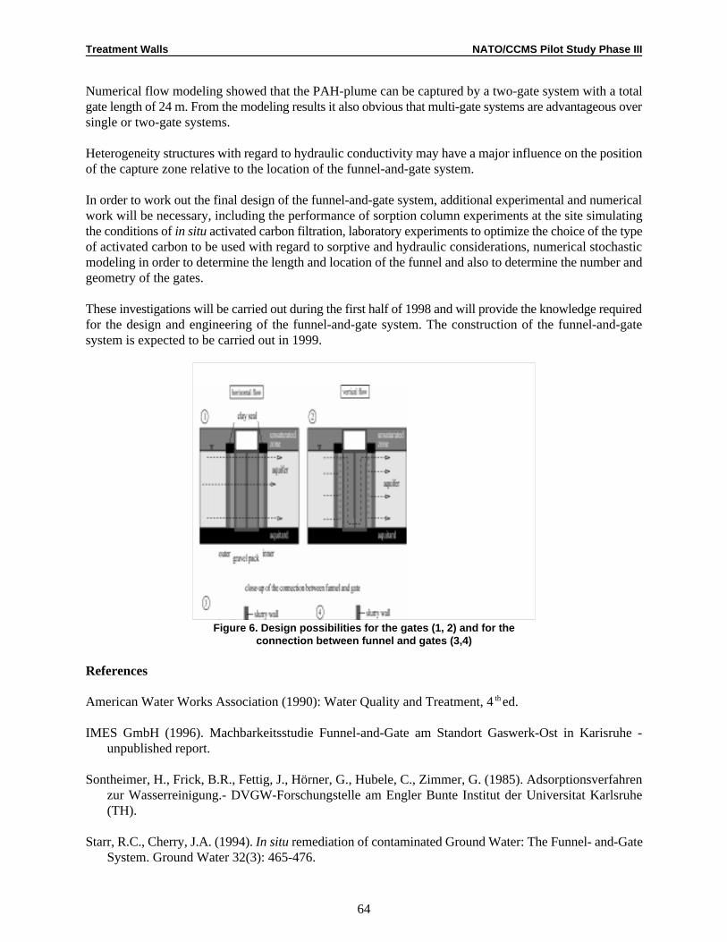
Treatment Walls NATO/CCMS Pilot Study Phase III
64
Numerical flow modeling showed that the PAH-plume can be captured by a two-gate system with a totalgate length of 24 m. From the modeling results it also obvious that multi-gate systems are advantageous oversingle or two-gate systems.
Heterogeneity structures with regard to hydraulic conductivity may have a major influence on the positionof the capture zone relative to the location of the funnel-and-gate system.
In order to work out the final design of the funnel-and-gate system, additional experimental and numericalwork will be necessary, including the performance of sorption column experiments at the site simulatingthe conditions of in situ activated carbon filtration, laboratory experiments to optimize the choice of the typeof activated carbon to be used with regard to sorptive and hydraulic considerations, numerical stochasticmodeling in order to determine the length and location of the funnel and also to determine the number andgeometry of the gates.
These investigations will be carried out during the first half of 1998 and will provide the knowledge requiredfor the design and engineering of the funnel-and-gate system. The construction of the funnel-and-gatesystem is expected to be carried out in 1999.
Figure 6. Design possibilities for the gates (1, 2) and for theconnection between funnel and gates (3,4)
References
American Water Works Association (1990): Water Quality and Treatment, 4 ed.th
IMES GmbH (1996). Machbarkeitsstudie Funnel-and-Gate am Standort Gaswerk-Ost in Karisruhe -unpublished report.
Sontheimer, H., Frick, B.R., Fettig, J., Hörner, G., Hubele, C., Zimmer, G. (1985). Adsorptionsverfahrenzur Wasserreinigung.- DVGW-Forschungstelle am Engler Bunte Institut der Universitat Karlsruhe(TH).
Starr, R.C., Cherry, J.A. (1994). In situ remediation of contaminated Ground Water: The Funnel- and-GateSystem. Ground Water 32(3): 465-476.

Treatment Walls NATO/CCMS Pilot Study Phase III
65
Teutsch, G., Grathwohl, P., Schad, H., Werner, P. (1996). In situ Reaktionswände - ein neuer Ansatz zurpassiven Sanierung von Boden- und Grundwasserverunreinigungen. Grundwasser, 1, 12-20.
Trischler und Partner (1996). Sanierung ehemaliges Gaswerk-Ost in Karlsruhe - unpublished report.
Discussion
Noting that carbon is an excellent medium for bacterial growth, Shad was asked how to prevent bacterialslime from clogging the system. He said that the system is anaerobic and must be maintained underanaerobic conditions. He has performed laboratory column tests at 20-25EC and did not observe bacterialgrowth. He also plans to perform sorption column tests under in situ conditions, using the same water, tofurther examine the potential for bioclogging.
Wolfgang Wüst asked about the sum of the dissolved organic carbon in the system. Schad was not sure, butsaid that there is highly organic material (including humic acids) present. Dissolved organic carbon will bethe main parameter examined during upcoming column tests. Schad will be assessing co-sorption ofcontaminants and variations in sorption rates.

Treatment Walls NATO/CCMS Pilot Study Phase III
Golder Associates (UK) Ltd, 54-70 Moorbridge Road, Maidenhead, Berkshire, SL6 8BN, England, +44-1628-771731,1
e-mail: [email protected] Nortel Ltd, Oakleigh Road South, New Southgate, London N11 1HB, England +44-181-945-3556, graham.norris@2
nt.com
66
Reactive Treatment Zones: Concepts and a Case History
Stephan A. Jefferis and Graham H. Norris1 2
ABSTRACT
The concept of the reactive treatment zone whereby pollutants are attenuated as they move along a pathwayin the ground has enabled a re-thinking of many of the concepts of containment. In particular it allows thecontrol of the flux from a contaminated area by controlling the contaminant concentration in the pathway(s)as well as or instead of using a low permeability barrier. This paper outlines the basic concepts of thereactive treatment zone and the use of permeable and low permeability reactive systems. It then gives a casehistory of the design, installation and operation of a reactive treatment zone using an in situ reactionchamber.
1. INTRODUCTION
The use of containment systems is now widely accepted for municipal and toxic waste landfill sites but upto now it has been more reluctantly accepted for the remediation of contaminated land. This reluctanceperhaps stems from a desire to use process orientated treatment technologies as a permanent means ofdealing with contaminated land problems. However, as the effectiveness of some in situ treatment tech-nologies remains in doubt and the costs of treatment in general remain relatively high, interest in contain-ment continues to develop and particularly in combining treatment with containment and the prospects forusing intrinsic processes as low cost longer term remedial options (Bardos and van Veen 1996).
1.1 Terminology
In the UK, it is common practice to refer to barrier systems that impede groundwater flow as passivecontainment systems, and the term “active containment” has been coined for those that reduce pollutant fluxby treating the contaminant(s) in a flow path between a source and a receptor. However, these terms are notuniversally accepted. For example, in Canada and the USA, “active containment” is often used to describeprocesses where there is an energy input, such as pump-and-treat systems, and the term “permeable barrier”is used for the UK’s “active containment.” In this paper the more general term “reactive treatment zone” willbe used for in-ground systems involving reactions that tend to reduce contaminant concentrations in apathway, and “passive containment” for barriers designed to impede flow.
2. REACTIVE TREATMENT ZONES
The essential feature of a reactive treatment zone is that contaminants can be controlled in a pathwaywithout necessarily preventing the flow of the carrier fluid (almost always water but gases are also amenableto such treatment).
Reactive treatment zones can be distinguished from passive (low permeability) containments by consideringthe controls on the flux, which for any contaminant may be written as:
Treatment Walls NATO/CCMS Pilot Study Phase III
67
Flux = Concentration x Permeability x Hydraulic gradient x Flow area
For a traditional passive barrier, the flux is controlled by ensuring that the permeability of the system is lowand hence that the flow through the barrier is low. However, as a result the flow area will be high as thebarrier must surround the source and the concentration(s) of the contaminant species and the hydraulicgradient (unless modified by pumping) also may be high.
An alternative way to control the flux is to reduce the concentration of the contaminant(s). If a sufficientreduction in concentration can be achieved then permeability ceases to be the controlling parameter and itmay be high or low as appropriate to the application. With a high permeability system the hydraulic gradientwill be low as the carrier fluid is allowed to escape and the area for flow may be less than that of a contain-ment as it may be deliberately focused with an engineered system or naturally higher permeability regionsmay be exploited—if they can be sufficiently well defined. This may simplify monitoring, and wherenecessary, in situ control. If space is available the input concentration may be varied by selecting the positionof the reactive zone in relation to the contaminant source or in-ground intrinsic remediation may beexploited upstream or downstream of the reactive treatment zone. It should be noted that reactive treatmentzones often will be used as pathway control mechanisms to prevent contaminants from a source reachinga receptor rather than as source clean-up technologies (at least in the short term).
2.1 Reactive Zone Configurations
In principle a reactive treatment zone or zones should completely enclose identified pathways from thepollutant sources to the receptors. In practice this may require that the zone(s) cover a substantial area.Furthermore the flow through any element of a zone may be uncertain as a result of factors includingseasonal variations in groundwater level and flow. It follows that large volumes of reactive material maybe necessary to ensure sufficient residence time throughout the zone under all operating conditions.Optimization of the deployment of the reactant is therefore an important consideration. Possibleconfigurations include:
• The use of injection wells to introduce chemicals into the natural groundwater flow. • The use of passive wells containing, for example, replaceable canisters of treatment materials that
dissolve into the natural groundwater flow. • Treatment zones in the region of the source that reduce pollutant concentrations to levels at which natural
intrinsic remediation can operate in zones down gradient of the source. • Systems that focus the flow either in plan or elevation or both.
It should also be possible to monitor and, if appropriate, control the processes within the treatment zone. Therequirements for monitoring and control can present problems for in situ treatments or intrinsic remediationin an undefined area, given the heterogeneity typically associated with ground conditions and the largevolumes of soil that may require treatment. Martin and Bardos (1996) describe examples of in situ treatmentzones where treatment remains in the ground but under conditions of better definition. The gate of a Funneland Gate system is an example of such a system where monitoring can be particularly straightforward andTM
control systems can be incorporated in the works if appropriate.
2.2 The Permeability of Reactive Treatment Zones
Reactions in a treatment zone may influence its permeability to the carrier fluid just as they may influencethe permeability of a passive containment. It follows that chemical, biochemical and physical phenomenawithin contaminant control systems must be recognized as interrelated. Contaminant control systems shouldbe considered as a continuum bounded by the two extreme situations:

Treatment Walls NATO/CCMS Pilot Study Phase III
68
• Permeable reactive treatment zones. The best known example is the use of zero valent iron todechlorinate solvents in groundwater (Gillham and O’Hannesin, 1992).
• Low permeability active containments, achieved, for example, by exploiting the chemistry of, or addingspecies to, low permeability barriers such as a soil-bentonite (Evans, 1991) or cement-bentonite (Jefferis,1996).
A reactive treatment zone must include some process that removes, destroys precipitates or otherwiseattenuates the contaminants migrating from the source(s) towards the receptor(s). Processes that may beemployed alone or in combination include: chemical reaction, physical separation, biological degradation,and sorption.
Many of these processes will rely on an interaction between the flowing groundwater and a solid phase inthe treatment zone and although the permeability of the zone is not the controlling parameter it may benecessary to consider it. For example, a moderate to high permeability may be necessary if problems suchas ponding within a containment are to be avoided. Designing and maintaining such a permeability may posesome problems as the reaction rate in the zone may be dependent on the surface area of a solid phase withinit. As a result it may be necessary to use finely divided (and hence low permeability) materials to limit therequired residence time of the contaminants in the zone. Also precipitates or biological slimes may formwithin the zone. Thus careful consideration must be given to the initial permeability of the treatment zoneand to processes that may lead to any change over time (an increase as well as a decrease in permeability canbe damaging if the water level or residence time in the reactive zone is sensitive to its permeability). It isperhaps ironic that a low permeability barrier may be compromised by an increase in its permeabilitywhereas a reactive treatment zone may be compromised by a decrease. The problems are reciprocal and ifone type of containment could be perfectly achieved there would be no need for the other.
2.3 Low Permeability Reactive Zones
Reactive treatment zones may be designed to be of low permeability, and the physical effect of the barriermay be enhanced by processes such as chemical reaction in the region of the barrier. For example, heavymetals may be precipitated by the high pH of cement-bentonite walls though credit is seldom given for thisin the design of such containments (except for the containment of radionuclides in purpose-designedrepositories).
A significant amount of work has been reported on the effect of contained chemicals on the physicalproperties of barrier materials such as clay liners and cement or soil-bentonite walls. The prime focus ofmuch of this work has been the assessment of physical damage to the cut-off material, for example, itspermeability that may be caused by contained chemicals. Much less work has been reported on the beneficialeffects of chemicals, though an examination of the literature shows that some work focused on the damagehas actually demonstrated beneficial effects.
Interactions in low permeability systems are potentially much more complex than in high permeabilitysystems as it is necessary explicitly to consider the effects of chemical, biochemical and mineralogicalchanges on the permeability and not just design to minimize their impacts. At the laboratory scale it has beendemonstrated that the chemical history of a containment material and its permeability can be stronglyinterlinked. For example, leaching a cement-bentonite material by sustained permeation with water, soreducing its pH, will usefully reduce its permeability and also inhibit expansive cracking and damage if itis subsequently exposed to sulfates. High pH, if required, can be re-established by permeation with lime andthis can further reduce the permeability but it will re-establish sensitivity to sulfates (Jefferis 1996).
Treatment Walls NATO/CCMS Pilot Study Phase III
69
That such interaction can occur is not surprising but it does raise questions about the interpretation oflaboratory investigations of chemical damage to barriers using samples that have not been exposed to thechemical history that occurs in situ (including, and very importantly, periods of leaching by water). Also ithas been demonstrated that some chemical damage can be reversed by re-introduction of appropriatechemical species. It follows that there is considerable potential to modify the behavior of barriers once inthe ground. This could be to repair them, extend their life, protect them from damaging species or modifyor re-charge their chemical activity. It is therefore quite simplistic to consider cement-bentonites and indeedmost passive barrier systems as having a unique permeability. They can be physically, chemically orbiochemically active and if we can learn to exploit this activity new barriers concepts will be forthcoming.
3. CASE HISTORY OF THE APPLICATION OF A PERMEABLE REACTIVE ZONE
In addition to the problems of design of reactive treatment zones with appropriate chemical reactions therecan be significant practical problems (and also opportunities) in fitting such systems to the circumstancesof a site and this is illustrated by the following case history.
At an industrial site in Belfast, Northern Ireland, currently being used for the manufacture of electroniccomponents, historic spillages of chlorinated solvents had led to an intense though localized contaminantsource and plume. A site investigation identified the following contamination in the groundwater:
• Trichloroethene (TCE) at concentrations up to 390 mg/l • Trichloroethane (TCA) at concentrations between 100 and 600 µg/l • Tetrachloroethene (PCE) at concentrations of the order of 100 µg/l
A particular problem with chlorinated solvents is that they tend to be of low solubility (typically less thanabout 1,000 mg/l) and thus can remain as a free phase product in the ground for substantial times but theregulatory control levels are typically of the order of tens of mg/l—i.e., of the order of one hundred thousandtimes less than their solubility. Also they are generally recalcitrant and not easily biodegraded. Thus evenquite a modest chlorinated solvent spill may persist in the groundwater and continue to pollute it for asubstantial time.
The soil profile at the site was complex, with glacial till interbedded with lenses of silts, sands and gravel.in situ pumping tests showed that the till acted as an effective barrier to the vertical and lateral migration ofthe contaminants but the silt, sand and gravel lenses were sufficiently permeable to allow off-site migrationof dissolved solvents from the source that included free phase solvents present as a dense non-aqueous phaseliquid (DNAPL). There were also smaller discrete lenses of clay or clayey silt that complicated the flowregime.
In situ permeability tests and pumping tests conducted to evaluate potential remedial strategies showed thatconventional pump and treat remediation would require numerous extraction wells to address the thinsaturated zone and this, together with the presence of a free product DNAPL source, meant that such asystem would have to be maintained for many years. Similarly there would be major problems with a soilvapor extraction system.
3.1 Reductive Dechlorination
One of the best known and researched reactive treatments is the use of iron filings to reductivelydechlorinate chlorinated solvents (Gillham and O’Hannesin, 1994). The process essentially leads to thedevelopment of an extremely reducing environment, allowing reactions occurring on the surface of the ironto strip halogens from the dissolved organic compounds as they flow through the zone. The reaction isabiotic and chlorinated solvents are converted to chloride ions and various hydrocarbons.
Treatment Walls NATO/CCMS Pilot Study Phase III
70
The process does not degrade the resulting hydrocarbons but as non-chlorinated species they have muchhigher permissible regulatory control concentrations. Also they are much more readily bio-degraded byintrinsic remediation processes occurring in the ground. The iron filings reactive containment is thus aconversion process that reduces toxicity. This demonstrates a general principle that a reactive treatment zoneneed not degrade organic contaminants to basic species such as carbon dioxide and water, but need onlyconvert them to species that are acceptable toxicologically and environmentally in the local setting.
The iron filings technology seemed to have potential for the Belfast site and samples of the site groundwaterobtained from sampling wells were shipped to EnviroMetal Technologies, Inc., Guelph, Ontario, fortreatability studies. The results of these studies are reported in Thomas et al. (1995). Briefly, a series oflaboratory column studies were undertaken to determine the degradation kinetics of the species of interestand to identify whether there were any constraints imposed by the natural geochemistry of the sitegroundwater. The results showed that TCE, PCE and TCA were completely degraded from initialconcentrations in the test groundwater samples of 300,000, 170 and 200 µg/l respectively. The half life ofTCE in the site water was estimated to be 1.2 hours in the presence of iron filings.
In contrast small concentrations of cis-dichloroethene (DCE) and vinyl chloride (VC) built up in the wateras a result of the dechlorination of the TCE, etc., with VC reaching a peak at the end of the column of 700µg/l in the initial studies. The reason for this is that although the dechlorination does not appear to be astepwise process (i.e., tetrachloroethene to tri- and then dichloroethene, vinyl chloride, and ultimately tochlorine-free hydrocarbons), and it seems that the majority of the solvent is dechlorinated in a single step.A small amount may be released from the surface of the iron prior to full degradation. This leads to atemporary increase in species, such as DCE and VC, as these species are more slowly dechlorinated by ironfilings. Considerable care was necessary in the design to ensure that the DCE and VC would be satisfactorilydegraded. Otherwise, the net effect of the treatment zone could be to increase the concentrations of thesespecies, which would be most unsatisfactory, particularly as vinyl chloride has markedly lower regulatorycontrol limits than many other chlorinated solvents.
Further column studies were then undertaken at lower flow rates, the increased residence time resulting inmuch earlier degradation of the parent compounds thus enabling estimation of the degradation rate of vinylchloride. From these laboratory trials, it was concluded that a residence time in contact with the iron filingsof about 12 hours was required for the site water to achieve removal of all chlorinated species to belowregulatory limits. This result, together with the results of a groundwater modeling exercise, enabled thecalculation of the required reactive zone path length from the estimated groundwater flow rate and therequired residence time of the contaminated groundwater in contact with the iron filings.
3.2 Design of the Reactive System
A preliminary review of the site situation concluded that the optimum strategy for deployment of the ironfilings was in the gate of a Funnel and Gate™ system. However, the site geology and site circumstancesplaced a number of constraints on the design:
• The contaminant source extended to within a few meters of the site boundary, outside which there wasa public road. The reactive treatment zone therefore needed to be very compact.
• The solvent source was underlain by a thin layer of clay, which had inhibited its migration to greaterdepths. If this layer were penetrated by the gate the free product solvents would sink and pollute a loweraquifer stratum.
• The groundwater perched on the thin clay layer was shallow and showed seasonal variations in depth.It would be difficult to maintain any significant depth of horizontal flow in a gate seated on this layer.
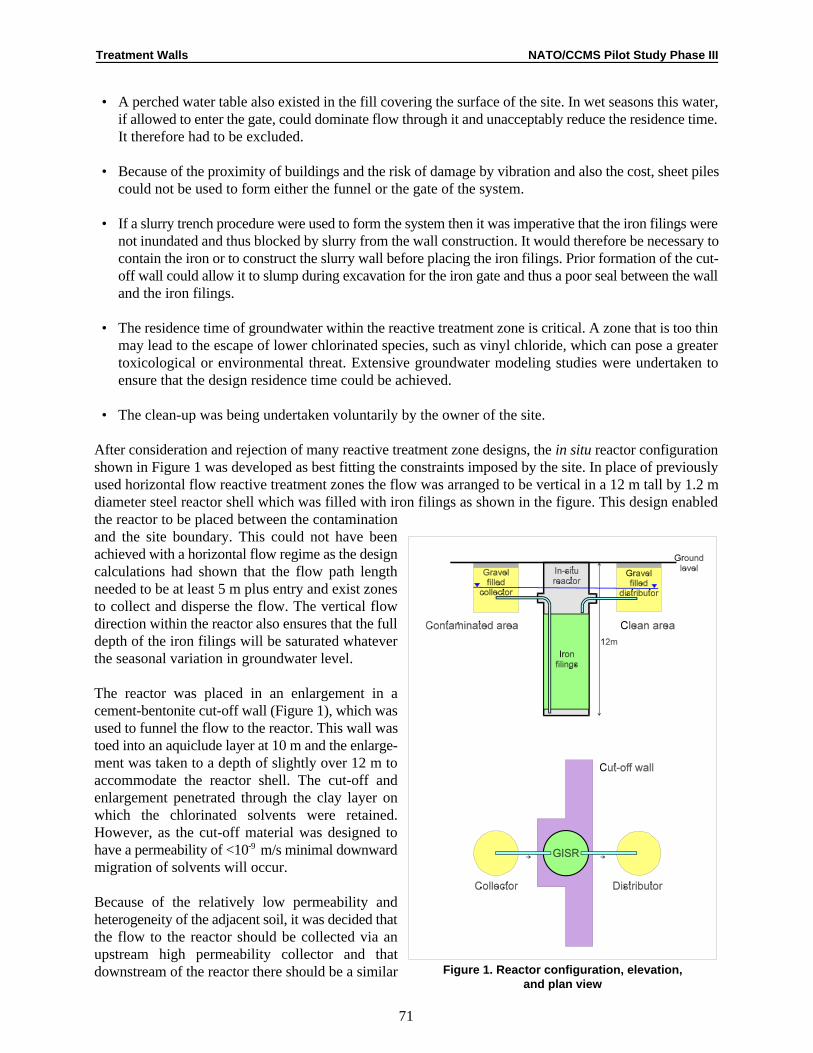
Treatment Walls NATO/CCMS Pilot Study Phase III
71
Figure 1. Reactor configuration, elevation,and plan view
• A perched water table also existed in the fill covering the surface of the site. In wet seasons this water,if allowed to enter the gate, could dominate flow through it and unacceptably reduce the residence time.It therefore had to be excluded.
• Because of the proximity of buildings and the risk of damage by vibration and also the cost, sheet pilescould not be used to form either the funnel or the gate of the system.
• If a slurry trench procedure were used to form the system then it was imperative that the iron filings werenot inundated and thus blocked by slurry from the wall construction. It would therefore be necessary tocontain the iron or to construct the slurry wall before placing the iron filings. Prior formation of the cut-off wall could allow it to slump during excavation for the iron gate and thus a poor seal between the walland the iron filings.
• The residence time of groundwater within the reactive treatment zone is critical. A zone that is too thinmay lead to the escape of lower chlorinated species, such as vinyl chloride, which can pose a greatertoxicological or environmental threat. Extensive groundwater modeling studies were undertaken toensure that the design residence time could be achieved.
• The clean-up was being undertaken voluntarily by the owner of the site.
After consideration and rejection of many reactive treatment zone designs, the in situ reactor configurationshown in Figure 1 was developed as best fitting the constraints imposed by the site. In place of previouslyused horizontal flow reactive treatment zones the flow was arranged to be vertical in a 12 m tall by 1.2 mdiameter steel reactor shell which was filled with iron filings as shown in the figure. This design enabledthe reactor to be placed between the contaminationand the site boundary. This could not have beenachieved with a horizontal flow regime as the designcalculations had shown that the flow path lengthneeded to be at least 5 m plus entry and exist zonesto collect and disperse the flow. The vertical flowdirection within the reactor also ensures that the fulldepth of the iron filings will be saturated whateverthe seasonal variation in groundwater level.
The reactor was placed in an enlargement in acement-bentonite cut-off wall (Figure 1), which wasused to funnel the flow to the reactor. This wall wastoed into an aquiclude layer at 10 m and the enlarge-ment was taken to a depth of slightly over 12 m toaccommodate the reactor shell. The cut-off andenlargement penetrated through the clay layer onwhich the chlorinated solvents were retained.However, as the cut-off material was designed tohave a permeability of <10 m/s minimal downward-9
migration of solvents will occur.
Because of the relatively low permeability andheterogeneity of the adjacent soil, it was decided thatthe flow to the reactor should be collected via anupstream high permeability collector and thatdownstream of the reactor there should be a similar
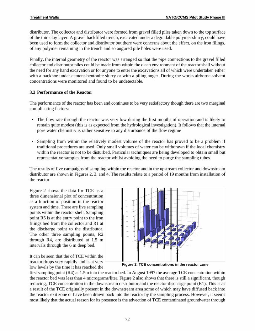
12-Aug-97
21-Jan-97
24-Oct-96
17-Jul-96
18-Apr-96
0
10,000
20,000
30,000
40,000
50,000
60,000
70,000
80,000
Treatment Walls NATO/CCMS Pilot Study Phase III
72
Figure 2. TCE concentrations in the reactor zone
distributor. The collector and distributor were formed from gravel filled piles taken down to the top surfaceof the thin clay layer. A gravel backfilled trench, excavated under a degradable polymer slurry, could havebeen used to form the collector and distributor but there were concerns about the effect, on the iron filings,of any polymer remaining in the trench and so augured pile holes were used.
Finally, the internal geometry of the reactor was arranged so that the pipe connections to the gravel filledcollector and distributor piles could be made from within the clean environment of the reactor shell withoutthe need for any hand excavation or for anyone to enter the excavations all of which were undertaken eitherwith a backhoe under cement-bentonite slurry or with a piling auger. During the works airborne solventconcentrations were monitored and found to be undetectable.
3.3 Performance of the Reactor
The performance of the reactor has been and continues to be very satisfactory though there are two marginalcomplicating factors:
• The flow rate through the reactor was very low during the first months of operation and is likely toremain quite modest (this is as expected from the hydrological investigation). It follows that the internalpore water chemistry is rather sensitive to any disturbance of the flow regime
• Sampling from within the relatively modest volume of the reactor has proved to be a problem iftraditional procedures are used. Only small volumes of water can be withdrawn if the local chemistrywithin the reactor is not to be disturbed. Particular techniques are being developed to obtain small butrepresentative samples from the reactor whilst avoiding the need to purge the sampling tubes.
The results of five campaigns of sampling within the reactor and in the upstream collector and downstreamdistributor are shown in Figures 2, 3, and 4. The results relate to a period of 19 months from installation ofthe reactor.
Figure 2 shows the data for TCE as athree dimensional plot of concentrationas a function of position in the reactorsystem and time. There are five samplingpoints within the reactor shell. Samplingpoint R5 is at the entry point to the ironfilings bed from the collector and R1 atthe discharge point to the distributor.The other three sampling points, R2through R4, are distributed at 1.5 mintervals through the 6 m deep bed.
It can be seen that the of TCE within thereactor drops very rapidly and is at verylow levels by the time it has reached thefirst sampling point (R4) at 1.5m into the reactor bed. In August 1997 the average TCE concentration withinthe reactor bed was less than 4 micrograms/liter. Figure 2 also shows that there is still a significant, thoughreducing, TCE concentration in the downstream distributor and the reactor discharge point (R1). This is asa result of the TCE originally present in the downstream area some of which may have diffused back intothe reactor exit zone or have been drawn back into the reactor by the sampling process. However, it seemsmost likely that the actual reason for its presence is the advection of TCE contaminated groundwater through

0
50
100
150
200
250
300
Collector R5 R4 R3 R2 R1 Distributor
Location
TCE
18-Apr-96
17-Jul-96
24-Oct-96
21-Jan-97
12-Aug-97
Total
18-Apr-96
17-Jul-96
24-Oct-96
21-Jan-97
12-Aug-97
Treatment Walls NATO/CCMS Pilot Study Phase III
73
Figure 3. Chlorine balance in the reactor zone
the distributor zone as a result of groundwater flow in the downstream area. It should not be forgotten thatthere may be a downstream flow vector parallel to as well through a gate.
Figure 3 shows the chlorine balance in the reactor zone. For this it is necessary to consider both the chlorinein the inorganic chloride ion and in the TCE. The TCE chlorine drops rapidly with distance into the reactorand only increases again in the distributor area. The total chlorine shown in the figure is the sum of the TCEand chloride chlorine and it can be seen that it is relatively consistent throughout the reactor (the high totalchlorine on 21 August 1997 was as a result of a high chloride ion concentration, the reason for it is notknown but could be as a result of some slight seepage of de-icing salts used in winter time.
On each sampling occasion TCA was at undetectable levels. Vinyl chloride was found at a single samplingpoint within the reactor at 4 months (at a level of 0.4 mg/l) but not in the collector or distributor and has notbeen detected on any subsequent occasion.
With regard to the remaining downstream contamination it is interesting to note, that at times of lowseasonal flow, there is potential for the recycling groundwater from wells downstream of the reactor to theupstream collector (by pumping) to treat the downstream area should treatment of this contamination berequired. Also the reactor will work with the flow in either direction. Thus, if, for some reason, the flowshould be reversed naturally then the site would be protected from the inflow of any contaminants spilledor remaining outside the reactor system.
4. CONCLUSIONS
The reactive treatment zone concept offers not only a new tool for the control of contamination but alsoforces a re-thinking of low permeability barrier systems. Prior to the development of the concept,contaminant/barrier interaction had generally been considered only as a possibly damaging process thatcould increase the permeability of a barrier. Now barrier interactions should be seen differently. They maybe deliberately engineered to be beneficial.

Treatment Walls NATO/CCMS Pilot Study Phase III
74
Reactive treatment zones may be most economically employed as pathway control procedures but willcontribute to the slow clean-up of a source. The pathway control they offer is their essential feature and itmay be argued that they should not be designed to achieve more than slow source clean-up as this minimizesthe rate at which any treatment chemicals, energy or other process inputs are required i.e. it minimizes theprocess demands and operating costs whilst maximizing the opportunity for natural, intrinsic, remediation.
At the present time a significant limitation to the use of reactive treatment zones is the rather narrow rangeof contaminants that can be treated and the complications introduced by mixed contaminants etc. However,work is in progress and the technology has strong parallels with intrinsic remediation (e.g., intrinsicbioremediation), and it is likely that the reactive treatment zone concept will find much application instimulating intrinsic degradation or attenuation.
The Funnel and Gate concept is a powerful adjunct to the technology as it can allow the treatment zoneTM
to be at some distance from the source, if this is required by surface or buried structures, geologicalconditions or for process optimization (e.g., exploiting natural dilution or attenuation in the soil), etc. Sitesneed not be capped to prevent rainwater ingress, indeed it can be an advantage in driving groundwater flowto a treatment zone.
The concept of an in situ reactor adds further flexibility to the design of reactive treatment zones, allowingmore precise control of the reactive zone and also recharging or recovery and replacement of the activematerial should this be required. Furthermore several reactors may be linked in series to treat mixedcontaminants.
Although most reactive treatment systems that have been advanced to date have been for the control ofgroundwater pollution there is no reason why other systems such as reactive caps should not be developedto control, for example, the escape of semi-volatile or volatile organics from petroleum impacted sites or gasor odor from landfills. Peat or humic based materials could be particularly cost effective in this respect (andof course for the removal of organics from impacted water). Bio-oxidation zones to control methanemigration through unsaturated soils offer some exciting prospects but there could be difficulties withexcessive local heating.
Low-permeability reactive treatment zones are a more specialist application and may require site cappingor groundwater pumping (and treatment) to avoid ponding. Reactive treatment zone concepts will be usefulwhere long term secure containment is necessary as chemical interactions can provide additional securityand lifetime to a physical containment. Furthermore the concepts may be useful in developing in situ repairstrategies for barriers that have suffered damage and in analyzing the effects of reaction on the permeabilityof these systems (Jefferis, 1996).
5. ACKNOWLEDGMENTS
Golder Associates gratefully acknowledges the proactive technical and financial support given by Nortel Ltdwho funded the reactive treatment project referred to in the case study.
The support of the UK Department of the Environment, Contaminated Land and Liabilities Branch, is alsogratefully acknowledged. They have funded Golder Associates to undertake a research project EPG 1/6/16on active containment concepts. This paper includes review work carried out for the Department of theEnvironment. However, the views expressed in this paper are those of the authors only and do notnecessarily reflect the views of the Department of the Environment. Reference to any individual ororganization or mention of any proprietary name or product in this paper does not confer any endorsementby the authors nor the Department of the Environment.
Treatment Walls NATO/CCMS Pilot Study Phase III
75
The award of an ERDF Northern Ireland Single Programme (1994 - 1999) Environmental Services andProtection Sub-Programme grant of 50% of qualifying costs associated with the Nortel reactive barrierproject is also gratefully acknowledged.
6. REFERENCES
Bardos, R.P. and J. van Veen. (1996) Longer term or extensive treatment technologies. Land Contamination& Reclamation, 4(1), pp. 19-36.
Evans, J.C., Y. Sambasivam and Z.R. Zarlinski. (1991) Attenuating materials in composite liners, WasteContainment Systems: Construction, Regulation and Performance, ASCE Geotechnical SpecialPublication, No 26.
Gillham, R.W. and S.F. O’Hannesin. (1994) Enhanced degradation of halogenated aliphatics by zero-valentiron, Groundwater, 32(6), pp. 958-987.
Gillham, R.W. and S.F. O’Hannesin. (1992) Metal catalysed abiotic degradation of halogenated organiccompounds, IAH Conference “Modern trends in Hydrogeology”. Hamilton Ontario, Canada, pp. 94-103.
Jefferis, S.A. (1996) Contaminant - barrier interaction: friend or foe? Mineralogical Society Conference,Chemical Containment of Wastes in the Geosphere.
Martin, I. and R.P. Bardos. (1996) A review of full scale treatment technologies for the remediation ofcontaminated soil. (Final report for the Royal Commission on Environmental Pollution, October 1995).EPP Publications, 52 Kings Road, Richmond Surrey.
Starr, R.C. and J.A. Cherry. (1994) In situ remediation of contaminated groundwater: The funnel-and-gatesystem, Groundwater, 32, pp. 465-476.
Thomas, A.O., D.M. Drury, G. Norris, S.F. O’Hannesin, and J.L. Vogan. (1995) The in situ treatment of
trichloroethene contaminated groundwater using a reactive barrier - results of laboratory feasibilitystudies and preliminary design considerations. Contaminated Soil ‘95, W.J. van den Brink, R. Bosman& F. Arendt (eds).
Discussion
There was some discussion concerning the placement of the reactor vessel relative to the collector anddistributor, and whether there would be any cost savings in installing the reactor at the same time as the cut-off wall, collector, and distributor. Jefferis replied that there are circumstances where there would be no costsavings for simultaneous construction. He said that sometimes it would be cheaper to build a pipe throughthe cut-off wall rather than place the reactor within it.
The reactor was designed to have a retention time of approximately 1 day. It is difficult to determine theexact flow through of the reactor because it was operated in the summer when the through-flow was too lowto measure. The highest flow occurs in the winter, and the reactor was designed for a maximum flow throughof 5 m/day. Other chemical parameters measured at the site were pH, PCE, DCE, vinyl chloride, and some3
inorganics.

Treatment Walls NATO/CCMS Pilot Study Phase III
76
Harald Burmeier questioned whether the groundwater was pumped through the reactor. Jefferis indicatedthat it is a gravity-flow reactor, but if necessary, groundwater could be pumped through to treat water, or topump down in the winter during peak flow to augment the low flow during the summer.
Wüst commented that the system seemed to work well, but wondered whether the hydraulic design wasadequate to clean up other contaminants besides TCE. Jefferis noted that no other contaminants werepresent, other than cis-DCE, which was found only in the distributor (not in the flow through). He addedthat the higher concentrations shown in Figure 2 were found in the distributor located downstream of thereactor. He said that the reactor has unused capacity, and he would like to pump back the flow through; heacknowledged his disappointment in how slowly the concentration was dropping. Geologically, it is a veryheterogeneous, complex site. There may be some cross-flow bringing in contamination directly from theplume.

Treatment Walls NATO/CCMS Pilot Study Phase III
Colorado School of Mines, Environmental Science and Engineering Division, Golden, CO. USA 80401-1887. Ph. 303-1
273-3490. Fax. 303-273-3490. Email. [email protected]. Oak Ridge National Laboratory, Environmental Sciences Division and Life Sciences Division, Grand Junction, CO.2
FRx, Inc., Cincinnati, OH and Clemson University, Clemson, SC. 3
Lockheed Martin Energy Systems, Inc., Piketon, OH. 4
77
Horizontal Treatment Barriers of Fracture-Emplaced Iron and Permanganate Particles
Robert L. Siegrist , Kathryn S. Lowe , Lawrence W. Murdoch ,1 2 3
Traci L. Case, Douglas A. Pickering , and Thomas C. Houk1 2 4
1.0 Abstract
In many contaminated sites, vertical leaching and/or volatilization of organic compounds can lead to highexposures and unacceptable human health or environmental risk. One remediation alternative for these sitesis to emplace horizontal treatment barriers to reduce the source concentration and mass as well as interceptand treat any mobile organics in the subsurface. Development and demonstration activities have beenconducted to evaluate the feasibility of creating horizontal treatment barriers by employing hydraulicfracturing for emplacement of chemically reactive solids. In this work, iron metal particles and a newpermanganate solid media were both tested in horizontal barriers to achieve interception and degradationof chlorocarbons like trichloroethene (TCE). Laboratory experiments were completed to develop suitabledelivery fluids and to determine reaction rates and efficiencies. The iron metal particles could be suspendedand delivered using a typical guar gum gel while the permanganate solids required a new mineral-basedcarrier fluid. Degradation of TCE at ~10 to 80% aqueous solubility with iron metal particles exhibited a half-life in the range of 1 to 2 hr while that of the permanganate solid was much faster with a half-life of onlyseveral min or less. A full-scale field test was subsequently conducted at an old land treatment site in themidwestern USA. Two test cells were installed with horizontal barriers comprised of reactive fracturesemplaced at ~1.2, 2.4, and 3.6-m depth in silty clay soils using hydraulic fracturing methods. After 3, 10 and15 mon of emplacement, continuous cores were collected across the emplaced fracture zones andmorphology was observed, geochemical properties were measured, and degradation tests were completedwith TCE contaminated groundwater (TCE concentrations at ~5-50% solubility). These analyses revealedstrong short-range trends in redox potential and pH consistent with the anticipated behavior of the twodifferent reactive media emplaced. Highly oxidizing zones were present in and around the permanganatebarriers. TCE degradation efficiencies during 2 hr of contact of >99% in 10-cm thick soil zones after ~3 monof emplacement with even broader effects at ~10 and 15 mon. The treatment barrier comprised of 200 µmiron-metal particles exhibited highly reducing conditions within the iron-metal fracture but no markedeffects in the soil zone surrounding it. Degradation of ~35% was achieved after 24-48 hr of contact but onlyin the iron-metal itself. The iron exhibited some corrosion, but this did not appear to affect its reactivity. Theresults of the work to date are very positive regarding the performance for both types of horizontal barriersand the estimated costs for a typical application are comparably low at only $30/m. Further work is ongoing3
to enable design and deployment of this technology.
2.0 Introduction
Petrochemicals (e.g., benzene) and chlorocarbons (e.g., TCE) are common and problematic contaminantsof concern (COCs) at federal facilities and industrial sites across the U.S. and abroad (USEPA, 1992; API,1995; DOE, 1996). These contaminants can be released to the environment through leaks in storage tanksand transfer lines, spills during transportation, and the land treatment of wastes. They are often present insource areas and in soil and groundwater plumes as dissolved or sorbed phase constituents as well asnonaqueous phase liquids (NAPLs). When these COCs are present in silt and clay media either as massive

Treatment Walls NATO/CCMS Pilot Study Phase III
78
surface deposits or as interbedded lenses in otherwise permeable formations, there are major challenges withassessment of their behavior and implementation of effective in situ remediation technologies. Despite a lowbulk permeability of silts and clays (e.g., K < 10 cm/s), organic compounds can contaminate fine-grainedsat
-7
deposits by preferentially moving into and through naturally occurring pore and fracture networks andpartitioning between the nonaqueous, gas, aqueous, and sorbed phases. In the unsaturated zone, organics cancontinually volatilize into the soil air or leach into percolating water while in the saturated zone they canslowly dissolve into advecting groundwater. Exposures and unacceptable risk can result from ingestion ofcontaminated drinking water or surface soil media, or inhalation of vapors in ambient air or emitted duringshowering events. In recognition of the severity of the problem and the need for effective in situ treatmentmethods, organic compounds in fine-grained deposits was recently ranked as one of the top environmentalrestoration needs across the DOE Complex (DOE, 1996). Similarly, within the petroleum industry, nearly40% of the underground storage tanks in the world are located on clay soils and leaking underground tanksand remediation of organic contamination in these settings remains a major challenge (API, 1995).
In situ remediation by conventional methods such as mass recovery by soil vapor extraction (SVE) or in situdestruction by biodegradation or chemical oxidation are often ineffective for NAPL compounds at sites withsilt and clay media. Poor accessibility to the contaminants and difficulty in delivery of treatment reagentsthroughout these deposits have made rapid and extensive in situ remediation difficult. Some aggressivetechniques have been developed involving subsurface disruption by soil mixing or alternative driving forcesbased on electrokinetics (e.g., Siegrist et al., 1995). In seeking less intensive methods that could be used overlarger areas, soil fracturing techniques have been developed whereby hydraulic or pneumatic fluids can beinjected to create permeable horizontal layers. This can increase the overall permeability of the subsurfaceand improve contaminant recovery as existing channels or pathways can be expanded or new channels orpathways can be created (U.S. EPA, 1993; Murdoch et al., 1997). Hydraulic methods normally employ anagent or proppant (e.g., sand) to fill and support the fracture opening that was created and thereby preventfracture closure during natural healing processes in unconsolidated deposits. If the fractures can be spacedthroughout the deposit, they potentially could be used to (1) enhance the recovery of organic compounds,(2) deliver and distribute treatment fluids into the deposit and accomplish destruction in place, or (3) placereactive solids as an integral part of the emplaced fracture that could serve as a horizontal treatment barrier.
Two reactive media that appeared appropriate for use in horizontal treatment barriers included: (1) ironmetal particles and (2) permanganate crystals. The use of zero valent iron metal as a reactive barrier mediahas been developed and deployed in vertical orientations for several years (e.g., O’Hannesin and Gillham,1998). The reductive dechlorination reaction for TCE is shown in equation 1. The reaction involves singleand multiple electron transfers following pseudo-first order kinetics (at least at lower TCE concentrations)with half-lives on the order of 30-60 min as normalized to solution to solid surface area. The pH of thereacting system tends to rise, but appears to stabilize in the pH 9-10 range due to iron hydroxideprecipitation.
2Fe+ C HCl + 3H O 6 C H Cl + H + Cl + 3OH + 2Fe [1]o - - ++2 3 2 2 2 2 2
The use of potassium permanganate for oxidative degradation of organic pollutants in contaminated landhas evolved over the past few years (e.g., Gates et al., 1995). The oxidative destruction of TCE is given inequation 2. The reaction can include destruction by direct electron transfer or free radical advancedoxidation. The reaction follows pseudo-first order kinetics and is very rapid with half-lives on the order ofsec to min. The pH of the reacting system can decline to very low values depending on the buffering capacityof the system.
2KMnO + C HCl 6 2CO + 2MnO + 2KCl + HCl [2]4 2 3 2 2
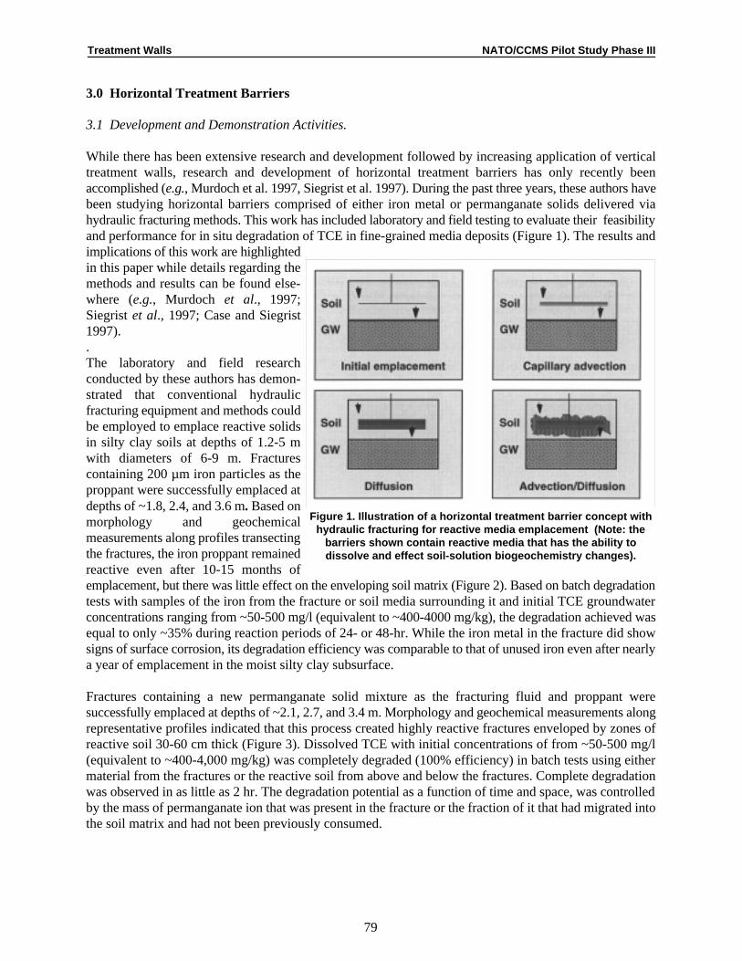
Treatment Walls NATO/CCMS Pilot Study Phase III
79
Figure 1. Illustration of a horizontal treatment barrier concept withhydraulic fracturing for reactive media emplacement (Note: the
barriers shown contain reactive media that has the ability todissolve and effect soil-solution biogeochemistry changes).
3.0 Horizontal Treatment Barriers
3.1 Development and Demonstration Activities.
While there has been extensive research and development followed by increasing application of verticaltreatment walls, research and development of horizontal treatment barriers has only recently beenaccomplished (e.g., Murdoch et al. 1997, Siegrist et al. 1997). During the past three years, these authors havebeen studying horizontal barriers comprised of either iron metal or permanganate solids delivered viahydraulic fracturing methods. This work has included laboratory and field testing to evaluate their feasibilityand performance for in situ degradation of TCE in fine-grained media deposits (Figure 1). The results andimplications of this work are highlightedin this paper while details regarding themethods and results can be found else-where (e.g., Murdoch et al., 1997;Siegrist et al., 1997; Case and Siegrist1997). . The laboratory and field researchconducted by these authors has demon-strated that conventional hydraulicfracturing equipment and methods couldbe employed to emplace reactive solidsin silty clay soils at depths of 1.2-5 mwith diameters of 6-9 m. Fracturescontaining 200 µm iron particles as theproppant were successfully emplaced atdepths of ~1.8, 2.4, and 3.6 m. Based onmorphology and geochemicalmeasurements along profiles transectingthe fractures, the iron proppant remainedreactive even after 10-15 months ofemplacement, but there was little effect on the enveloping soil matrix (Figure 2). Based on batch degradationtests with samples of the iron from the fracture or soil media surrounding it and initial TCE groundwaterconcentrations ranging from ~50-500 mg/l (equivalent to ~400-4000 mg/kg), the degradation achieved wasequal to only ~35% during reaction periods of 24- or 48-hr. While the iron metal in the fracture did showsigns of surface corrosion, its degradation efficiency was comparable to that of unused iron even after nearlya year of emplacement in the moist silty clay subsurface.
Fractures containing a new permanganate solid mixture as the fracturing fluid and proppant weresuccessfully emplaced at depths of ~2.1, 2.7, and 3.4 m. Morphology and geochemical measurements alongrepresentative profiles indicated that this process created highly reactive fractures enveloped by zones ofreactive soil 30-60 cm thick (Figure 3). Dissolved TCE with initial concentrations of from ~50-500 mg/l(equivalent to ~400-4,000 mg/kg) was completely degraded (100% efficiency) in batch tests using eithermaterial from the fractures or the reactive soil from above and below the fractures. Complete degradationwas observed in as little as 2 hr. The degradation potential as a function of time and space, was controlledby the mass of permanganate ion that was present in the fracture or the fraction of it that had migrated intothe soil matrix and had not been previously consumed.

Treatment Walls NATO/CCMS Pilot Study Phase III
80
Figure 2. Features of iron metal horizontal barriers 10 months afterinitial emplacement in a silty clay soil (after Siegrist et al. , 1997).(a) Media redox potential and pH above and below the horizontal
treatment fracture. (b) TCE degradation potential above and belowthe horizontal treatment fracture as measured in batch tests using
3-5 g of media in 40 ml of groundwater.
3.2 Discussion and Implications.
The viability of reactive fracturesemplaced by hydraulic fracturingmethods as horizontal barrier systemsrequires consideration of the horizontalcontinuity, degradation capacity, andlongevity. The results obtained by theseauthors enable a very interesting contrastbetween reactive fractures created withsurface reactive particles (i.e., iron metalparticles) versus those created with areactive grout that dissolves and yields awider reactive zone (i.e., permanganategrout). Both types of reactive mediawere successfully handled and emplacedby conventional hydraulic fracturingequipment and methods. The geometryof the fractures was similar to that ofconventional sand-filled fracturesemplaced at the same site. Thus, therewas no unusual behavior associated withthe different fracturing proppants (i.e.,iron particles in guar gum versuspermanganate particles in mineral carrierversus sand in guar gum).
Since the iron metal fractures arediscrete reactive sheets, it is not likelythat these fractures would be self-healingwithin or between fractures or effectivebeyond the boundary of initialemplacement. This challenges the fracture emplacement to be continuous and uniform horizontally with nobreaches through it. Also, degradation of the TCE or related compounds within the deposit must rely on theirbeing mobilized to the fracture where they can contact the metal surface. Since the TCE reaction rates withiron metal are comparatively slow, any mobile contaminants must remain in contact with the iron metal fora reasonably long period of time (e.g., on the order of 18-24 hr). If flow through the fracture is controlledby unsaturated conductivity in the surrounding soil media and assuming the conductivity is about 10 cm/s,-6
then the retention time in a fracture of 5 mm thickness could be on the order of a day or more depending onthe effective porosity in the iron. Thus, adequate retention time can be reasonably expected. As a treatmentbarrier, the reactivity of the iron surface would need to exist for an extended period (e.g., 2-5 years or more).Analysis of the micromorphology of the surface of the unused and used iron metal revealed some corrosionof the iron surface after emplacement for ~10 months. The effect was limited however to only a fraction ofthe available iron surface and this corrosion had no apparent effect on TCE degradation. Whether this wouldhold true for longer emplacement periods is currently unknown.
With permanganate fractures, the dissolution of the solid permanganate particles will yield MnO ions that4-
will enter the soil solution and migrate away from the original location of emplacement by advection and/ordiffusion. This will yield an oxidizing zone that can treat TCE within the affected zone enveloping thefracture as well as intercept and degrade mobile contaminants that enter the oxidation zone. This behaviorsuggests that the permanganate fractures will be somewhat self-healing internally and between horizontally

Treatment Walls NATO/CCMS Pilot Study Phase III
81
(a) Media redox potential and pH above and below the horizontaltreatment fracture.
Figure 3. Features of permanganate horizontal barriers asobserved 10 months after initial emplacement (after Siegrist et al.,
1997).
(b) TCE degradation potential above and below the horizontal treatmentfracture as measured in batch tests using 3-5 g of media in 40 ml of
groundwater.
proximal fracture emplacements. Withregard to longevity, the permanganatesolids present in a 5 mm thick fracturecontains about 0.4 g KMnO per cm or4
2
fracture horizontal area Based oncomplete oxidation and a stoichiometricdose of ~2.5 wt./wt., each cm of2
fracture can treat ~0.16 g of TCE, whichis equivalent to roughly 16 l of percolatewith a concentration of 10 mg/l of TCE.At a deep percolation flux of 1 cm/day,this potential is equivalent to about 50years of life. Realistically though, it isanticipated that advective loss of oxidantout of the treatment region or the oxidantdemand of natural organic matter willmarkedly diminish this life. Based ondirect observation in this study, theoxidation capacity within and around thepermanganate fracture was very higheven after 10-15 months ofemplacement. If alkenes, such as TCE,were migrating downward in percolatinggroundwater at reasonably high levels(e.g., 10-100 mg/l), the capacity of thefractures seemingly would be highenough to intercept and treat this mobileTCE.
The cost of a horizontal treatment barriercomprised of reactive fractures such astested in this study were estimated.When compared to standard hydraulicfracturing and SVE, the major cost differences would be added costs for the reactive media (~$1.6/lb forpermanganate and ~$0.38/lb for iron metal) as compared to standard fracturing sand (~$0.10/lb) but loweroperational costs. The costs for media per fracture amounts to roughly $100 for sand, $1,000 for iron, and$1,500 for permanganate. This increases the installation cost for the iron and the permanganate fractures.However with lower resource consumption (e.g., power), less sampling and analysis (e.g., no off-gas),reduced labor requirements, and no off-gas treatment costs, the operational costs would be substantiallylower for the horizontal barriers as compared to fracture-enhanced vapor extraction. For a 2.2 ha site anda 5-m deep zone of contamination, the costs for emplacement of horizontal treatment barriers was estimatedto be in the range of $30/m. 3
In summary, horizontal treatment barrier systems appear viable for TCE contaminated sites with silt and claydeposits. Further work is necessary and appropriate, however, to fully develop this horizontal treatmentbarrier approach and provide needed design and performance data for a range of full-scale applications. Forexample, information is still needed on the depth and interval of emplacement as well as reactivity anddegradation capacity over time. The behavior of horizontal barrier systems under conditions of forcedadvection also needs to be evaluated to understand the benefits/costs of recirculation approaches to in situtreatment and source area mass reduction as opposed to more passive barriers for simple interception andtreatment.

Treatment Walls NATO/CCMS Pilot Study Phase III
82
4.0 References
American Petroleum Institute. 1995. Petroleum Contaminated Low Permeability Soil: HydrocarbonDistribution Processes, Exposure Pathways and In Situ Remediation Technologies. Health andEnvironmental Sciences Dept. Publication No. 4631. Sept. 1995.
Case, T. 1997. Reactive Permanganate Grout for Horizontal Permeable Barriers and In Situ Treatment ofGroundwater. M.S. Thesis. Colorado School of Mines, Golden, CO.
Case, T.L. and R.L. Siegrist. 1997. Oxidation Kinetics of Trichloroethylene in Groundwater by Perman-ganate under Varying Matrix Conditions. J. Water Environment Research. In review.
DOE. 1996. In Situ Remediation of DNAPL Compounds in Low Permeability Media: Transport/Fate, InSitu Control Technologies, and Risk Reduction. Oak Ridge National Laboratory Report, ORNL/TM-13305, for the U.S. Department of Energy. August, 1996.
Gates, D.D., R.L. Siegrist, S.R. Cline. 1995. Chemical Oxidation of Volatile and Semi-Volatile OrganicCompounds in Soil. Proc., Air and Waste Management Association Conf. June.
Murdoch, L., B. Slack, B. Siegrist, S. Vesper, and T. Meiggs. 1997. Hydraulic Fracturing Advances. CivilEngineering. May 1997. pp. 10A-12A.
O’Hannesin, S.F. and R.W. Gillham. 1998. Long-term Performance of an In Situ “Iron Wall” forRemediation of VOCs. Ground Water. 36(1):164-170.
Siegrist, R.L., O.R. West, J.S. Gierke, et al. 1995. In Situ Mixed Region Vapor Stripping of LowPermeability Media. 2. Full Scale Field Experiments. Env. Sci. and Technol. 29(9):2198-2207.
Siegrist, R.L., K.S. Lowe, L.C. Murdoch, D.A. Pickering, T.L. Case. 1997. In Situ Oxidation by FractureEmplaced Reactive Solids. J. Environmental Engineering. In review.
U.S. EPA. 1992. Dense Nonaqeuous Phase Liquids—A Workshop Summary. EPA/600/R-92/030. Officeof Research and Development, Washington, D.C. 20460.
U.S. EPA. 1993. Hydraulic Fracturing Technology—Technology Evaluation Report. EPA/540/R-93/505.Office of Research and Development, Cincinnati, OH.
Discussion
Noting the rapid release rate for permanganate, Resat Apak asked whether permanganate sheets can be usedonly in low-permeability aquifers. Siegrist acknowledged that his work involves the use of permanganategrout in low-permeability zones; however, there is work being done with controlled releases of perman-ganate. With a slower release rate, perhaps the technology can be tailored to higher permeability zones.
Apak also whether Siegrist has observed clogging due to the formation of manganese hydroxide. Siegristnoted that the product of the reaction between manganese and TCE is manganese oxide precipitate, whichranges in size from 1-2 µm. The formation of the solids is somewhat related to the concentration of reactants.Siegrist has observed limited formation of solids at the test site, but has not seen an accumulation at theinterface. Clogging has not been a problem with low-permeability zones, but may be a problem with higherpermeability zones.

Treatment Walls NATO/CCMS Pilot Study Phase III
83
Paul Bardos questioned whether the capacity of the permanganate is reduced due to oxidation of organicmatter in the soil. Siegrist agreed that permanganate is an oxidant that reacts with TCE and natural organicmatter in the soil. However, permanganate does not seem to be consumed as much by the organic matter.Siegrist noted that residual permanganate remains in zones with organic material after 15 months; however,the soil matrix should be assessed for the potential to consume the permanganate.
The cost difference between using permanganate and iron is not significant. The cost per fracture of usingsand alone is approximately US$100. The cost per fracture is US$1,000 for iron and US$1,500 forpermanganate. The retention time in the iron-filled fracture is 1-5 days, during which there is 30-40 percentdegradation. Siegrist noted that the cost estimate of US$30/m that he cited during his presentation applies3
to both iron and permanganate. Both materials appear to be viable, although they have differentcharacteristics.

Treatment Walls NATO/CCMS Pilot Study Phase III
UFZ – Centre for Environmental Research Leipzig-Halle, Department Industrial and Mining Landscapes, P.O. Box 2,1
D - 04301 Leipzig, Germany
“Sanierungs-Forschung In Regional kontaminierten Aquiferen” – Remediation Research in Regionally Contaminated2
Aquifers
84
In Situ Remediation Research in a Complexly Contaminated Aquifer:The SAFIRA Test Site at Bitterfeld, Germany
H. Weiss , F.-D. Kopinke, P. Popp, and L. Wünsche1
The experience of the last 20 years has shown that hydraulic soil and groundwater remediation schemes areoften very ineffective. This is especially true of large-scale pollution, where the source of contaminationeither cannot be precisely located or is problematical to remove. Owing to the frequently low solubility ofhydrophobic organic substances (for example), the existence of a separate residual phase, the usually unevensubterranean flow, and the sometimes slow return diffusion of pollutants that have penetrated the rock overa period of years or even decades, solely hydraulic remediation can only achieve limited clean-up. Theconsequences are very prolonged (and thus expensive) pump-and treat remedies, whose completion isusually impossible to predict.
Against the background of the now generally acknowledged problems of pump-and-treat activities, intensivework has been carried out in recent years on developing low-price in situ remediation measures. Thecurrently most advanced remediation technology working in the flow is that of “in situ reaction/adsorptionwalls” [1], which have already been tried out for simple pollutant mixtures (e.g., LCKW, BTEX, and PAK)at a number of model sites. Nevertheless, there is still a great deal of development work to be done withrespect to the complex pollutant mixtures commonly encountered above all in the vicinity of abandonedchemical plants.
As this problem is extraordinarily important in connection with the large-scale ecological remediationschemes in eastern Germany, the SAFIRA project has been set up to examine and further develop the usage2
of in situ reaction walls at a contaminated model field location.
In order to create the necessary basis for this model project, a preliminary study was carried out by UFZ incooperation with the Universities of Dresden, Halle, Leipzig, Stuttgart, and Tübingen. During the course ofthis preliminary study, the hydrogeological and hydrogeochemical conditions at the planned field locationwere investigated and various technologies for the design of the in situ pilot plant were examined and tested.
Choosing the Model Location
The Bitterfeld region was selected as the model location for investigations into developing powerful in situtechnologies for the remediation of complexly contaminated groundwater.
The soil and water environmental compartments in the Bitterfeld/Wolfen district have suffered sustaineddamage as a result of over a century of lignite-mining and chemical industry. Whereas relevant soil pollutionis mainly confined to industrial locations (plant sites) and landfills, the persistent penetration of thegroundwater by pollutants has resulted in contamination attaining a regional scale. Consequently, an areaof about. 25 km with an estimated volume of some 200 million m is now partly highly polluted and must2 3

Treatment Walls NATO/CCMS Pilot Study Phase III
85
Figure 1. Geological section (E–W) at the experimental site in the Bitterfeld area
be regarded as an independent source of contamination [2]. This pollution is characterized by the extensivedistribution of halogenized hydrocarbons, especially chlorinated aliphatics and chlorinated aromatics.
The development of the hydraulic conditions and thus regional pollutant transport is determined by thedraining techniques used for lignite-mining and its subsequent abandonment, as well as the imminentflooding of Goitsche opencast mine. Since 1990, the hydraulic and conditions have been described andevaluated in several studies (e.g., [2, 3, 4]; for further reading see [5]), so that there is an extraordinarily highlevel of knowledge concerning the area in question. The containment and remediation concepts drafted since1994 [2-4] feature both “active” and “passive” hydraulic containment measures to minimize groundwatermobility. Successive measures to contain landfills (e.g., encapsulation) are also being discussed. “Active”measures for groundwater remediation on a regional scale are not under consideration owing to the volumesinvolved and the ad infinitum emission of pollutants from the landfills.
Given this background, Bitterfeld appears especially appropriate as the SAFIRA model location fordeveloping methods and technologies for minimally invasive “passive” decontamination techniques forcomplexly polluted groundwater within a genuine scenario, as well as demonstrating their suitability in thefield. The results of the feasibility study for the experimental site are compiled in [6]. Figure 1 contains ageological section of the area under investigation.
Pollution
Groundwater
Contamination of the groundwater with inorganic pollutants (e.g., heavy metals, arsenic, etc.) has provedminor. The only noteworthy feature is the high levels of sulphate (up to 1,000 mg/l) and chloride (1,300mg/l).
In order to characterize the organic pollution of the groundwater at the various water levels, several sampleswere examined from different levels. The “main components” of organic contamination were found to be

Treatment Walls NATO/CCMS Pilot Study Phase III
86
chlorobenzene, 1,2-dichlorobenzene, 1,4-dichlorobenzene, benzene, trichloroethene, cis-1,2-dichloroetheneand trans-1,2-dichloroethene. Mass-spectrometry screening also detected other substances, albeit in very lowconcentrations.
Although high organic pollution with halogenated hydrocarbons was confirmed in both the upper and loweraquifers, contamination considerably varied between the two in terms of both quality and quantity. The loweraquifer is dominated by aliphatic chlorinated hydrocarbons (trans-1,2-DCE, cis-1,2-DCE and TCE), whilethe main component of the upper aquifer is chlorobenzene. During depth-oriented sampling, contaminationwas found to display significant stratification: whereas the sample from a depth of 7-8 m only contains verylow amounts of pollutants, samples from depths between 16 and 20 m were above all found to contain highlevels of chlorobenzene (8-51 mg/l), as well as substantial concentrations of dichlorobenzenes (up to 1 mg/l).
Solid samples from the cores
In addition to the water samples, core material was also examined. The core samples from bore Saf Bit 2/96were subjected to headspace-screening over the entire profile between 0 and 48.5 m. The relative sensitivi-ties, which are proportional to the concentration of the substances in the sample, are summarized in Figure2, showing clearly the influence of the lignite seam on the contaminant distribution.
One striking aspect is that the aliphatic halogen hydrocarbons and benzene chiefly occur in the stratabetween 19.5 m and 24.5 m, while chlorobenzene and the dichlorobenzenes are found in higher concen-trations in the strata between 12 m and 22.65 m. The main components are trans-1,2-dichloroethene, cis-1,2-dichloroethene, chlorobenzene, trichloroethene, and benzene. Bromobenzenes and perchloroethene were alsoidentified by mass spectrometry.
Investigations into the adsorption and desorption of the pollutants in coal samples revealed that the sorptioncapacity of the coal has not yet been exhausted. Hence the coal can act as both a pollutant sink (highconcentrations in the groundwater) and a pollutant source (lower concentrations of the pollutants in thegroundwater).
Laboratory Experiments on Pollutant Decomposition
Bioremediation
The basic requirements for deciding whether microbiological in situ remediation techniques can in principlebe used, selecting the most suitable technique and assessing the prospects of success are as follows:
C Determining the microbial density.
C Determining the pollutant breakdown capacity of the autochthonous microbial biocenoses underin situ conditions.
C Examining ways of boosting the breakdown capacities of autochthonous microbial biocenosesin situ using technically and financially feasible measures.
C Determining the microbial density.
C Determining the pollutant breakdown capacity of the autochthonous microbial biocenoses underin situ conditions.
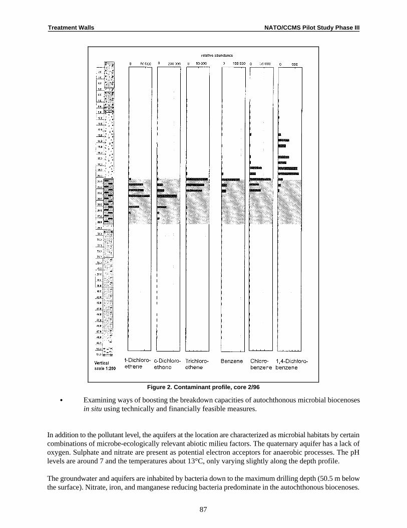
Treatment Walls NATO/CCMS Pilot Study Phase III
87
Figure 2. Contaminant profile, core 2/96
C Examining ways of boosting the breakdown capacities of autochthonous microbial biocenosesin situ using technically and financially feasible measures.
In addition to the pollutant level, the aquifers at the location are characterized as microbial habitats by certaincombinations of microbe-ecologically relevant abiotic milieu factors. The quaternary aquifer has a lack ofoxygen. Sulphate and nitrate are present as potential electron acceptors for anaerobic processes. The pHlevels are around 7 and the temperatures about 13°C, only varying slightly along the depth profile.
The groundwater and aquifers are inhabited by bacteria down to the maximum drilling depth (50.5 m belowthe surface). Nitrate, iron, and manganese reducing bacteria predominate in the autochthonous biocenoses.

time [d]
0 10 20 30 40
0
20
40
60
80
100
time [d]
0 10 20 30 40
Benzene
MCB
1,2-DCB
1,4-DCB
time [d]
0 10 20 30 40
0
20
40
60
80
100
time [d]
0 10 20 30 40
time [d]
0 10 20 30 40
A B
D EC
%
%
Treatment Walls NATO/CCMS Pilot Study Phase III
88
Figure 3. Decomposition of chlorobenzenes and benzeneby autochthonous bacteria groups in the boundary layerof the quaternary aquifer and coal (19-23 m beneath thesurface)
Figure 3. a) Without the addition of substrates (Aaerobic; B-E anaerobic; B without additionalelectron acceptors; C nitrate; D sulfate; Ehydrated iron oxide)
b) With the addition of substrates (lactate,acetate, yeast extract, ammonium, andphosphate); A-E
As expected, a lack of yeasts and mycelium-forming fungi was found in most habitats; a tiny abundance(<5×10 g ) was only detected in the coal-bearing strata, individual horizons of the quaternary aquifers (6,2 –1
16–17 and 19–21 m) and the tertiary aquifer at 48 m.
The pollutants found to be the main contaminants in the quaternary aquifer were selected for investigationsinto microbiological breakdown. These were monochloro-benzene (MCB, 30 mg/l), 1,2-dichlorobenzene(1,2-DCB, 10 mg/l) and 1,4-dichlorobenzene (1,4-DCB, 10 mg/l). Benzene (100 mg/l) was also includedin the investigation as the expected product of the chemically catalyzed dehalogenation of chlorobenzenes.
The three primary pollutants MCB, 1,2- and 1,4-DCB (as well as benzene) were removed from the auto-chthonous bacteriocenoses under simulated in situ conditions within technologically relevant periods oftimes. However, the extent and speed of removal significantly differed depending on the pollutants’chemical structure, the metabolism type of the ecophysiological groups involved, and the availability ofelectron acceptors and additional carbon substrates (Figure 3).
Of the three chloroaromatics, 1,2-DCB easily proved to be the hardest compound to break down; in factunder anaerobic conditions no decomposition whatsoever was established without the availability ofadditional carbon substrates. After adding non-resident carbon substrates (a mixture of acetate and lactate),the 1,2-DCB was however almost completely removed after just 20 days under nitrate, sulphate and ironreducing conditions. When using these approaches, the other pollutants were no longer detectable either bythis time.
Under aerobic conditions, 1,2-DCB was in all experiments only broken down very slowly (if at all). Theresidual concentrations found after an incubation time of 40 days were usually 40 – 50 %, and in just onecase about 30% of the initial concentration - thus on the whole they were only slightly below the residualconcentration of 50 % defined as the evaluation limit for biological removal.
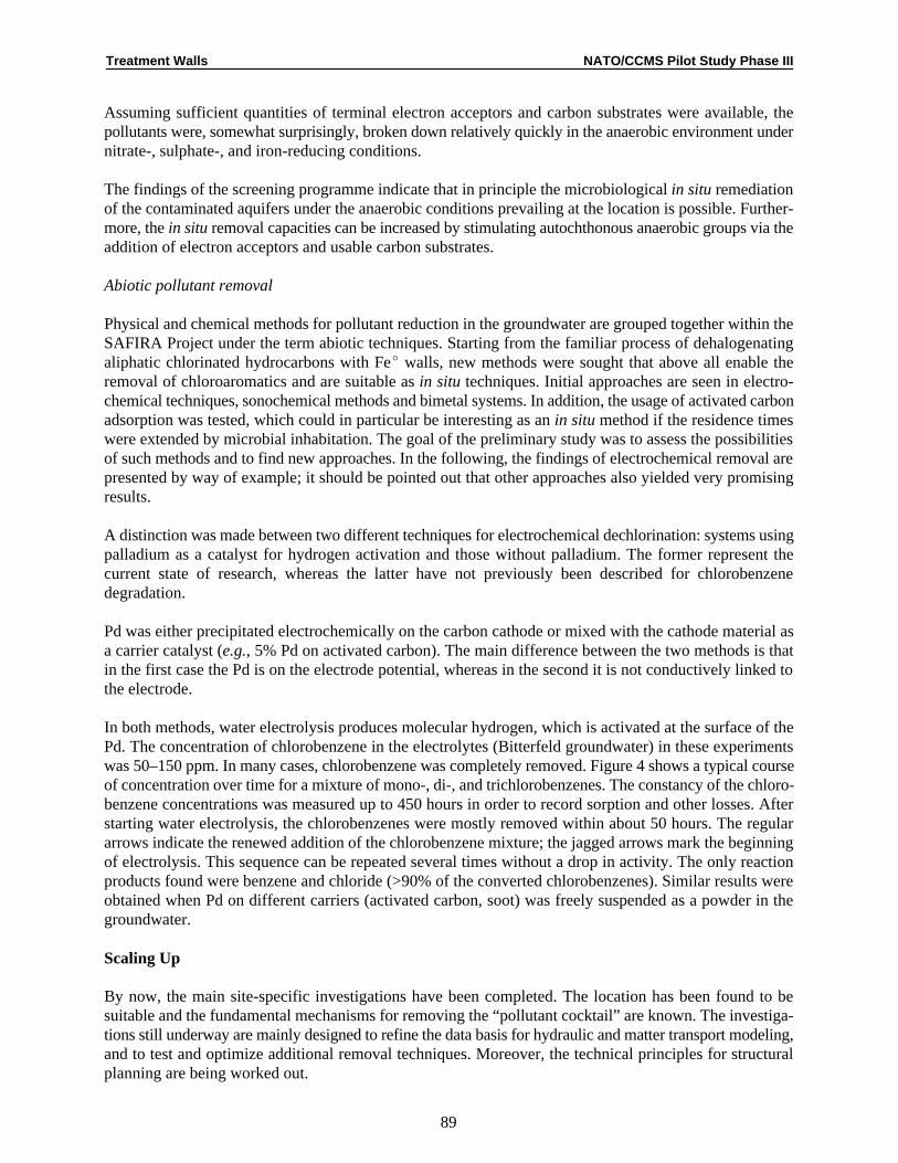
Treatment Walls NATO/CCMS Pilot Study Phase III
89
Assuming sufficient quantities of terminal electron acceptors and carbon substrates were available, thepollutants were, somewhat surprisingly, broken down relatively quickly in the anaerobic environment undernitrate-, sulphate-, and iron-reducing conditions.
The findings of the screening programme indicate that in principle the microbiological in situ remediationof the contaminated aquifers under the anaerobic conditions prevailing at the location is possible. Further-more, the in situ removal capacities can be increased by stimulating autochthonous anaerobic groups via theaddition of electron acceptors and usable carbon substrates.
Abiotic pollutant removal
Physical and chemical methods for pollutant reduction in the groundwater are grouped together within theSAFIRA Project under the term abiotic techniques. Starting from the familiar process of dehalogenatingaliphatic chlorinated hydrocarbons with FeE walls, new methods were sought that above all enable theremoval of chloroaromatics and are suitable as in situ techniques. Initial approaches are seen in electro-chemical techniques, sonochemical methods and bimetal systems. In addition, the usage of activated carbonadsorption was tested, which could in particular be interesting as an in situ method if the residence timeswere extended by microbial inhabitation. The goal of the preliminary study was to assess the possibilitiesof such methods and to find new approaches. In the following, the findings of electrochemical removal arepresented by way of example; it should be pointed out that other approaches also yielded very promisingresults.
A distinction was made between two different techniques for electrochemical dechlorination: systems usingpalladium as a catalyst for hydrogen activation and those without palladium. The former represent thecurrent state of research, whereas the latter have not previously been described for chlorobenzenedegradation.
Pd was either precipitated electrochemically on the carbon cathode or mixed with the cathode material asa carrier catalyst (e.g., 5% Pd on activated carbon). The main difference between the two methods is thatin the first case the Pd is on the electrode potential, whereas in the second it is not conductively linked tothe electrode.
In both methods, water electrolysis produces molecular hydrogen, which is activated at the surface of thePd. The concentration of chlorobenzene in the electrolytes (Bitterfeld groundwater) in these experimentswas 50–150 ppm. In many cases, chlorobenzene was completely removed. Figure 4 shows a typical courseof concentration over time for a mixture of mono-, di-, and trichlorobenzenes. The constancy of the chloro-benzene concentrations was measured up to 450 hours in order to record sorption and other losses. Afterstarting water electrolysis, the chlorobenzenes were mostly removed within about 50 hours. The regulararrows indicate the renewed addition of the chlorobenzene mixture; the jagged arrows mark the beginningof electrolysis. This sequence can be repeated several times without a drop in activity. The only reactionproducts found were benzene and chloride (>90% of the converted chlorobenzenes). Similar results wereobtained when Pd on different carriers (activated carbon, soot) was freely suspended as a powder in thegroundwater.
Scaling Up
By now, the main site-specific investigations have been completed. The location has been found to besuitable and the fundamental mechanisms for removing the “pollutant cocktail” are known. The investiga-tions still underway are mainly designed to refine the data basis for hydraulic and matter transport modeling,and to test and optimize additional removal techniques. Moreover, the technical principles for structuralplanning are being worked out.

6 0 0 7 0 0 8 0 0
C h l o r o b e n z e n e
D i c h l o r o b e n z e n e
T r i c h l o r o b e n z e n e
1000000
2000000
3000000
100 200 300 400 500
0
0
E q u i l i b r a t i o n t i m e ( v o l t a g e o f f ) A d d i t i o n o f s t o c k s o l u t i o n
t i m e [ h ]
E l e c t r o l y s i s ( 5 V D C )
Treatment Walls NATO/CCMS Pilot Study Phase III
90
Figure 4. Reductive dechlorination of mono-, di- and trichlorobenzenes (c = 100 ppm MCB, 30 ppm DCB and0
10 ppm TCB) on Pd (5 wt-% on 15 mg activated carbon) with hydrogen produced by electrolysis (cathode:150 mg electrographite, U = 5 V, I = 2 mA, electrolyte: 150 ml groundwater) .
The next stage is to scale up the experiments carried out so far in the laboratory. For this purpose a mobiledecontamination unit has been designed as a “window in the aquifer”. Groundwater from a depth of about20 m is pumped into a storage tank without coming into contact with oxygen from the air. This pollutedwater will then be used to charge five possible test columns with the physico-chemical conditions of theaquifer being preserved (T = 13°C, pH = 7, eH = -250 mV, P = 2.5 mS/cm, AOX � 100 mg/l).
The methods tested successfully in the laboratory and in the mobile decontamination unit have to prove theirchemical and hydrological long term stability and will be optimized in a pilot plant. Several vertical,experimental columns (up to 3 m in diameter) will be installed to a depth of 20 m directly into the aquifer.Numerous sampling and process controlling facilities and a variable design of the reaction columns willenable the analyses of relevant chemical and hydraulic processes during operation and a competitivetechnology development under real-world conditions. Operation of the pilot plant will start by the end of thisyear. Subsequently an extension of the pilot plant for a horizontal groundwater flow is intended.
References
[1] Teutsch, G, Grathwohl, P., Schad, H. and Werner, P. (1996): In situ-Reaktionswände - ein neuer Ansatzzur passiven Sanierung von Boden- und Grundwasserverunreinigungen.- Grundwasser 1/96, 12-20.
[2] Peter, H., Großmann, J. and Schulz-Terfloth, G. (1995): Rahmensanierungskonzept des Großprojektes“Bitterfeld/Wolfen”.- In: LÜHR, H.-P. (Hrsg.): Grund-wassersanierung 1995.- IWS Schriftenreihe, 23:123-138; Berlin, Erich Schmidt-Verlag
[3] Schulz-Terfloth, G. and Walkow, F. (1996): Maßnahmen zur Sanierung des Grundwassers unterBerücksichtigung der wasserwirtschaftlichen und bergbaulichen Situation im Großprojekt Bitterfeld-Wolfen.- In: LÜHR, H.-P. (Hrsg.): Grund-wassersanierung 1996.- IWS Schriftenreihe, 27: 307-320;Berlin, Erich Schmidt-Verlag
[4] Landratsamt Bitterfeld / GFE GmbH: Grundwassermonitoring 1992-1996.

Treatment Walls NATO/CCMS Pilot Study Phase III
91
[5] Großmann, J. and Lühr, H.-P. (1994): Sanierungsrahmenkonzept für Großprojekt Bitterfeld-Wolfen.
[6] Weiß, H., Teutsch, G. and Daus, B. (Hrsg.) (1998): Sanierungsforschung in regional kontaminiertenAquiferen (SAFIRA) - Bericht zur Machbarkeitstudie für den Modellstandort Bitterfeld.- UFZ-Bericht27/1997, ISSN 0948 94252; Januar 1998; Leipzig
Discussion
Kahraman Ünlü asked whether the removal of iron chloride is a concern. Weiss noted that lowering chlorideconcentrations is not feasible due to the presence of underground brine.
Weiss was asked if he considered using iron to produce hydrogen because it is cheaper than producing itelectrolytically. Weiss indicated the oxygen that is produced in the electrolytical reaction can be used foraerobic reactions.
One of Weiss’s photographs showed gas bubbles being produced at the water surface during the reaction,which were identified as methane and nitrogen.
Treatment Walls NATO/CCMS Pilot Study Phase III
92
Summary and Conclusions
Harald Burmeier
Construction of Treatment Walls
The costs of pilot studies and field studies should be considered when computing the costs of implementinga technology. The costs presented for the funnel-and-gate technology only reflect the materials (iron) andconstruction. Field demonstrations are not conducted very frequently anymore; in most cases, laboratorystudies suffice. At approximately 90 percent of the North American sites for which treatment walls, TCEor PCB is the primary contaminant; with few exceptions, the half-lives fall within a narrow range (30minutes to 1 hour). Therefore, it becomes difficult to justify field tests as cost-effective.
Eberhard Beitinger recently performed field tests with two columns of activated carbon at a site with severaltypes of contaminants. The columns were installed on site to model actual conditions. The results of thecolumn tests were very encouraging; the performance time of the wall would be higher than had beenexpected. The minimum time designed for the wall was 30 years for the first removal of reactive materials.A 50-m continuous wall will be installed with impermeable “wings.”
Although residence times to degrade chlorinated solvents are generally known, geological and hydro-geological characterization is needed for any treatment approach. Furthermore, information on the plume’slocation and where it is moving is also necessary. If this information is well understood, design costs canbe lowered.
Harry Whittaker doubted that chromium can be removed permanently with an iron treatment wall becauseiron becomes very finely divided ferric oxide in the environment, especially in wet soils. He suggested thatthere is a continuous long-term cycle of Fe, Fe , FeE, and Cr and Cr . Once all of the iron is converted2+ 3+ 3+ 6+
to Fe , the chromium that was retained by the treatment wall will be released. Wolfgang Wüst added that3+
he has seen this occur in column tests.
Bob Puls said that the state environmental agency in North Carolina had to be convinced that chromatewould not be released eventually from the permeable reactive barrier (PRB) at Elizabeth City. Originally,natural attenuation of the chromate was examined. There was a natural reduction of chromate observed(primarily due to the high organic carbon content of the surface soils), and the chromate was immobilizedin a chromium and iron hydroxide phase. Researchers had to prove to the regulatory authority that the ironwould not reoxidize the Cr to Cr . The only oxidant in natural soil strong enough to oxidize chromium3+ 6+
is manganese oxide. As a result, they analyzed the manganese oxide content of the soil and groundwater toprove that whatever immobilization method was occurring would not reverse itself. The PRB was notconsidered a permanent remedy for the chromate plume, and they are looking into eliminating the chromatesource.
Harald Burmeier said that long-term aspects of installing treatment walls must be considered during thefeasibility study. For example, the construction of the wall should be approached so that the reactive mediacan be removed and replaced as necessary. Although it may be relatively inexpensive to construct atreatment wall, the need to remove it 30 years in the future must be considered in cost estimates.
Paul Bardos asked if there is any true distinction between permeable reactive barriers and treatment walls.Burmeier explained that permeable reactive barriers are a type of treatment wall that uses a material that ispermeable and reactive to treat the groundwater. Treatment walls can also be partially permeable and treat

Treatment Walls NATO/CCMS Pilot Study Phase III
93
groundwater using adsorptive, biological, or electrochemical processes. In addition to treatment wallconstruction, treatment barriers can be constructed as piles, drainage trenches, and funnel and gate systems.
There was additional discussion on the issue of patents for treatment walls. To the extent that EnviroMetalTechnologies has a worldwide patent on the emplacement of iron in the ground for remediation ofchlorinated organic solvents, there may be cases where researchers are not adhering to the patent restrictions.Hermann Schad indicated that the funnel-and-gate patent applies to situations where groundwater flow isdiverted toward the treatment wall. This design is protected in Germany and several other countries in theEuropean Union. Schad noted that funnel-and-gate systems are advantageous when intending to use amaterial to react with or absorb a contaminant. The continuous walls, however, have hydraulic advantages.
In response to a question regarding treatment walls that do not work as designed, Burmeier acknowledgedthat the examples presented in the session emphasized successes rather than failures. However, heemphasized that reactive materials must be tested prior to emplacement. He added that when building a wallover 10 to 20 m deep, technologies must be matched to the permeability of the subsurface as well. Gillhamwas aware of at least three cases in the United States where regulators required a contingency for theinstallation of a reactive barrier. He added that in any case, an alternative treatment method is almost alwaysproposed along with the reactive barrier.
Walt Kovalick emphasized that the cost savings of using PRBs instead of pump-and-treat systems is signifi-cant. He suggested that 10 to 20 percent of the pump-and-treat systems currently active in the United Statescould benefit from the installation of PRBs. The issue of contingencies was insignificant from a coststandpoint because the cost of a typical wall (US$400 thousand) is significantly less than a pump-and-treatsystem (US$12-14 million). Therefore, the cost of research and development is also justified.
Reactive Materials, Full-Scale Projects, and General Conclusions
Harald Burmeier summarized the topics discussed and the questions on treatment walls that still remain tobe answered. He pointed out that the Special Session presentations have examined the reaction, absorption,and degradation processes of treatment walls, but noted that combinations of processes are also beingconsidered.
Several issues need closer examination, such as how to estimate and influence the long-term performanceof treatment wall; determination of by-products of organic contaminant degradation; the cost of materials(e.g., the range in costs and corresponding effectiveness of zero-valent irons); calculation of mass balances;the determination of what reactive substances can be placed in the groundwater without risk; and how toinfluence biological processes in combination with treatment walls.
The presentations showed that zero-valent iron can be used to degrade chlorinated solvents and adsorburanium, but the nature and toxicity of the adsorbed uranium still must be determined. Clearer explanationsare needed from scientists on how to evaluate degradation and sorption processes. Optimization of reactivematerials using bench-scale tests have frequently been replaced by laboratory tests followed by trial-and-error field testing. Further research on bioscreens is needed to determine long-term effects on remediationas well as possible limiting factors such as bioclogging, redox limitations, and concentrations orcombinations of contaminants. There are questions beyond technological solution, that cross into regulatory,legal, and public policy, such as what concentration of a contaminant is harmless? Can reactive materialsbe emplaced in the groundwater, and at what concentrations? What is the long-term implication of in situchemical engineering, including any production of toxic by-products?

Treatment Walls NATO/CCMS Pilot Study Phase III
94
From the standpoint of constructing treatment walls, good definitions of terms such as “permeable reactivebarriers” and “treatment walls” must be developed. Although it is now possible to excavate and install deepwalls, the cost effectiveness of such constructions should be evaluated in order to access the market.
In conclusion, treatment wall technology has been proven to work; however, there are some limitations toits use. Several questions still must be answered before their use can become widespread.

Treatment Walls NATO/CCMS Pilot Study Phase III
95
ABOUT THE AUTHORS
Harald Burmeier is a civil engineer with 20 years of experience in waste and hazardous waste management,contaminated site investigations, feasibility studies, and health and safety issues. A professor of engineeringon the faculty of Applied Studies and Research of the University of Northeast Lower Saxony, Prof. Burmeiermaintains an active consulting practice throughout Germany on project management for waste and hazardouswaste remediation, issues related to worker health and safety, and emissions control. He is the author of anumber of books and articles on hazardous waste investigation, management, and remediation. Prior toassuming his present position last year, Prof. Burmeier held a series of senior technical and managementpositions in the German construction industry and trade associations. Prof. Burmeier holds a M.S. in CivilEngineering from the Technical University of Hannover, Germany.
Gérard Evers is a senior engineer and head of the Department of Technique and Development at SoletancheBachy (Nanterre, France), the world’s largest specialized contractor in foundation techniques andunderground construction. Mr. Evers holds a diploma in civil engineering from the Technical High Schoolof The Netherlands.
Robert Gillham has been a professor in the Department of Earth Sciences at the University of Waterloosince the early 1970s. He was Director of the Waterloo Centre for Groundwater Research from 1987 to 1992,was Chair of the Earth Sciences Department from 1993 to 1997, and currently holds the NSERC/Motorola/ETI Industrial Research Chair in Groundwater Remediation. In 1997 Dr. Gillham was elected a Fellow ofthe Royal Society of Canada. Dr. Gillham’s primary research areas concern contaminant transport ingroundwater systems and groundwater remediation.
Liyuan Liang received her B.S. in civil engineering from Northeastern University and her M.S. and Ph.D.in Environmental Engineering from the California Institute of Technology. Dr. Liang is Senior Lecturer inthe Department of Earth Sciences, University of Wales (UK), where she teaches aquatic geochemistry andenvironmental remediation technologies, conducts research on physico-chemical processes, and directs theVirtual Institute for Environmental Research. Prior to her current appointment, she was at Oak RidgeNational Laboratory (USA), where she managed a group of researchers investigating in situ phsico-chemicaltreatment technologies for groundwater remediation and on the mechanistic understanding of geochemicalprocesses in the environment. She also conducted research on colloidal transport in groundwater, the kineticsof reductive dechloriantion of organic solvents using zero-valent metals, and on the peroxidation of organiccontaminated soils. While at Oak Ridge, she was a member of the Steering Committee of the U.S. PermeableReactive Barriers Action Team. Her primary research interests include in situ treatment technologies formixed-wastes (organic solvents and radionuclides); laboratory and field research on particle dynamics inaquatic environments (including coagulation, dispersion, and transport of colloidal particles); oxidativeprecipitation and mineral dissolution; and fate of metals and organic contaminants in the environment. Dr.Liang has published extensively in refereed journals.
Stephan Jefferis (M.A., M.Eng., M.Sc., Ph.D., C.Eng., M.I.C.E., C.Geo.l, F.G.S.) has qualifications innatural sciences, chemical engineering, civil engineering, and law. He spent 20 years, with the Universityof London (UK) where his research group developed a class of cement-bentonite cut-off materials that hasbeen used at many contaminated sites in Europe. Dr. Jefferis is presently an associate of Golder Associates,where his role is world-wide and typically involves the investigation and resolution of unusual geotechnical,geoenvironmental and materials problems often associated with aggressive chemical and microbiologicalprocesses in the ground. He is also a visiting professor in the Department of Civil Engineering, ImperialCollege, London.
Treatment Walls NATO/CCMS Pilot Study Phase III
96
Robert W. Puls has a B.S. in Soil Science and Natural Resources from the University of Wisconsin, aMasters degree in Forest Resources from the University of Washington, and a Ph.D. degree in Soil andWater Science from the University of Arizona. He has worked as a Research Soil Scientist at the R.S. KerrEnvironmental Research Center, of the National Risk Management Research Laboratory of U.S. EPA inAda, Oklahoma since 1987. Prior to that he worked for DOE in Richland, Washington on the High LevelNuclear Waste Repository Research Program. He has more than 19 years experience working in theenvironmental science field. Dr. Puls is the current Co-Chair of the Permeable Reactive Barrier ActionTeam, one of seven Action Teams comprising EPA’s Remedial Technology Development Forum (RTDF).He has been actively involved in research related to permeable reactive barriers since 1991. His recentpublications have covered a range of topics including groundwater sampling, colloidal transport ingroundwater, organic-metal-mineral interactions, the development and evaluation of in situ remediationtechniques for soils and groundwater, and metal and metalloid sorption-desorption reactions governingsubsurface contaminant transport and transformation processes. He has authored more than 50 publicationson the above topics and given numerous presentations at national and international scientific meetings. Dr.Puls has served on several scientific advisory committees for USEPA, the USGS, DOE and the NationalResearch Council.
Huub H. M. Rijnaarts earned his M.Sc. degree in soil chemistry and soil microbiology and his Ph.D. fromthe University of Wageningen Agricultural University (The Netherlands), where he studied bacterialtransport in porous media and biodegradation of hazardous organic compounds. Since 1994, Dr. Rijnaartshas been a Senior Researcher with The Netherlands Organization for Applied Scientific Research (TNO)Institute of Environmental Sciences, Energy Research and Process Innovation, where he has been involvedin developing new in situ soil and groundwater bioremediation techniques, including biological barriers, andnatural attenuation.
Hermann Schad holds an M.S. and Ph.D. in geology from the University of Oregon (USA) and theUnviersity of Tübingen (Germany), respectively. His Ph.D. thesis was on the “Variabliity of HydraulicParameters in Non-Uniform Porous Media: Experiments and Stochastic Modelling at Different Scales.” Dr.Schad presently is the Waste Management Director of I.M.E.S. (Innovative Mess-, Erkundunes- undSanierungstechnologien GmbH) in Wangen, Germany.
Robert L. Siegrist earned his B.S. and M.S. in Civil Engineering and his Ph.D. in EnvironmentalEngineering at the University of Wisconsin. During 20 years of experience, he has held research andteaching appointments with the Colorado School of Mines, Oak Ridge National Laboratory (ORNL), theUniversity of Wisconsin, and the Agricultural University of Norway. Since January 1995, Dr. Siegrist hasbeen affiliated with Colorado School of Mines (USA) as a research associate professor in the EnvironmentalScience and Engineering Division while also holding an adjunct faculty participant position as a senior staffmember in the Environmental Sciences Division at ORNL. His research has focused on characterization,assessment, and in situ remediation technologies for contaminated land. The technology related work hasincluded in situ treatment processes (chemical oxidation, redox reactive barriers, bioremediation) as wellas subsurface manipulation methods (vertical and horizontal recovery and recirculation wells, lancepermeation, deep soil mixing, hydraulic fracturing). In related work, Dr. Siegrist has continued research intothe hydrodynamic and purification processes impacting land treatment and disposal of wastes. Since 1990,Dr. Siegrist has been leading a program of research concerning in situ chemical ozidation involving peroxideand permanganate systems including fundamental studies of oxidation reaction chemistry and kinetics,contaminant mass transfer, oxidant delivery systems, and field evaluations through pilot- and full-scaletechnology demonstrations. His research has been sponsored by the U.S. Department of Energy, U.S. EPA,the U.S. Department of Defense, the National Science Foundation, and private industry. He has publishedhis results in over 35 refereed articles and more than 100 conference proceedings and reports. He is an activemember of several national societies and currently servces on national committees, including theGroundwater, Hazardous Waste, and McKee Medal Committees of the Water Environment Federation. he

Treatment Walls NATO/CCMS Pilot Study Phase III
97
is a registered professional engineer and has served as an advisor and technical expert for state and federalagencies in the United States, Canada, Norway, and Sweden. He is currently a Fellow with NATO/CCMS.
Timothy M. Vogel received his B.S. degrees in biological oceanography and geology and his M.S. inenvironmental engineering from the University of Washington (USA), and his Ph.D. in environmentalengineering (microbiology) from Stanford University (USA). Following his graduate studies, Dr. Vogeltaught at Michigan State University and the University of Michigan. Between 1992 and 1997, he heldpositions of research and management with Rhône-Poulenc Industrialisation and, since 1998, he has beenthe research and development project manager for Rhodia Eco Services in Meyzieu, France. His currentresearch activities include the acquisition, evaluation, and development of novel technologies for theremediation of polluted soil and groundwater. Reactive barriers are among his most intense researchsubjects, based on his previous scientific research involving the development of reductive dechlorinationsystems—such as vitamin B12—and on the biodegradation of petroleum hydrocarbons.
Holger Weiss is Head of the Department of Industrial and Mining Landscapes at the Center ofEnvironmental Research, Leipzig-Halle (Germany), where he coordinates interdisciplinary and internationalresearch on contaminated and degraded landscapes, minimization of environmental impacts of mineralexploitation and development, landscape reclamation, and ecosystem stability in industrial and mining areas.He is conducting research on in situ technologies for complexly contaminanted aquifers (active and passive;physico-chemical; microbiological), on the environmental significance and human and ecological affectsfrom industrial residues, and on regional emissions and effects of choro-organic contaminants. Dr. Weissholds a Ph.D. in geology from the Technical University of Clausthal, Lower Saxony (Germany), and he haspublished extensively in the peer-reviewed literature in the United States and Europe.
Wolfgang Wüst was born in Nördlingen (Bavaria, Germany). After high school he got a scholarship fromthe state Bavaria and decided to study Geoökologie (Environmental Sciences) at the University of Bayreuthand Lancaster (UK) with the focus on environmental chemistry and modeling of pollutant transport anddegradation. In 1990 he received his diploma on the transport of heavy metals from the street into sewersystems in the working group of Professor R. Herrmann. He continued his training in the field ofhydrogeology and groundwater hydraulics at the chair of groudwater hydraulics (Prof. Kobus) and wasinvolved in different research projects related to groundwater remediation in the VEGAS facility at theUniversity of Stuttgart. Since three years he is focussing on the chemical processes defining the scope andthe limitations of permeable reactive iron walls (working group of Professor Dahmke) and will soon finishhis Ph.D. on this topic.

Treatment Walls NATO/CCMS Pilot Study Phase III
98
NATIONAL CONTACTS
Treatment Walls NATO/CCMS Pilot Study Phase III
99
Directors
Stephen C. James (Co-Director) Walter W. Kovalick, Jr. (Co-Director)National Risk Management Research Laboratory Technology Innovation OfficeU.S. Environmental Protection Agency U.S. Environmental Protection Agency26 Martin Luther King Drive 401 M Street, SW (5102G)Cincinnati, Ohio 45268 Washington, DC 20460United States United Statestel: 513-569-7877 tel: 703-603-9910fax: 513-569-7680 fax: 703-603-9135e-mail: [email protected] e-mail: [email protected]
Co-Pilot Directors
Volker Franzius H. Johan van VeenUmweltbundesamt The Netherlands Integrated Soil ResearchBismarckplatz 1 ProgrammeD-14193 Berlin P.O. Box 37Germanytel: 49/30-8903-2496fax: 49/30-8903-2285 or -2103 tel: 31/317-484-170
NL-6700 AA WageningenThe Netherlands
fax: 31/317-485-051e-mail: [email protected]
Country Representatives
Nora Auer Harry WhittakerFederal Ministry of Environment, Youth and Emergencies Engineering DivisionFamily Affairs Environment CanadaDept. III/3 3439 River RoadStubenbastei 5 Ottawa, Ontario, K1A OH3A-1010 ViennaAustriatel: 43/1-515-22-3449 fax: 613/991-1673fax: 43/1-513-1679-1008 e-mail: [email protected]: [email protected]
Jacqueline Miller Aquatest a.s.Brussels University Geologicka 4Avenue Jeanne 44 152 00 Prague 51050 BrusselsBelgiumtel: 32/2-650-3183 fax: 420/2-581-77-58fax: 32/2-650-3189 e-mail: [email protected]: [email protected]
Canadatel: 613/991-1841
Jan Švoma
Czech Republictel: 420/2-581-83-80
Treatment Walls NATO/CCMS Pilot Study Phase III
100
Inge-Marie Skovgård Matthew CroweContaminated Land Division Environmental Management and PlanningDanish Environmental Protection Agency Division29 Strandgade Environmental Protection AgencyDK-1401 Copenhagen K P.O. Box 3000Denmarktel: 45/3-266-0100 - direct 45/32660397 County Wexfordfax: 45/3-296-1656e-mail: [email protected] tel: +353 53 60600
Ari Seppänen e-mail: [email protected] of EnvironmentP.O. Box 399 Takeshi Nishio00121 Helsinki Soil and Agricultural Chemicals DivisionFinlandtel: +358/9-199-197-15 Japan Environment Agencyfax: +358/9-199-196-30 1-2-2, Kasumigaseki, Chiyoda-Ku
René GoubierPolluted Sites Team tel: +81-3-3580-3173ADEME fax: +81/3-3593-1438B.P. 406 e-mail: [email protected] Angers Cedex 01Francetel: 33/241-204-120 Ministry for the Environmentfax: 33/241-872-350 84 Boullcott Street
Antonios Kontopoulos Wellington*
National Technical University of AthensGR-157 80 Zografos tel: 64/4-917-4000Athens fax: 64/4-917-7523Greece
Pál Varga Bjørn BjørnstadNational Authority for the Environment Norwegian Pollution Control AuthorityFö u.44 P.O. Box 8100 DepH-1011 Budapest N-0032 OsloHungary Norwaytel: 36/1-457-3530 tel: 47/22-257-3664fax: 36/1-201-4282 fax: 47/22-267-6706e-mail: [email protected] e-mail: [email protected].
Johnstown Castle Estate
Ireland
fax: +353 53 60699
Environment Agency, Water Quality Bureau
Tokyo 100Japan
Raymond Salter
P.O. Box 10362
New Zealand
e-mail: [email protected]
telemax.no
Ewa MarchwinskaInstitute for Ecology of Industrial Areas 6 Kossutha Street40-833 KatowicePolandtel: 48/32 -1546-031fax.: 48/32 -1541-717e-mail: [email protected]
*Due to the death of Prof. Kontopoulos,communications with the Greek delegation to the PilotStudy may be directed to: Manolis Papadopoulos, tel: +30-1-772 2219; fax:+30-1-772 2218, e-mail [email protected]

Treatment Walls NATO/CCMS Pilot Study Phase III
101
Marco Estrela Resat ApakInstituto de Soldadura e Qualidade Istanbul UniversityCentro de Tecnologias Ambientais Avcilar Campus, Avcilar 34850Estrada Nacional 249–Km 3–Leiao (Tagus Park) IstanbulApartado 119 - 2781 Oeiras CodexPortugaltel: +351/1-422-8100 fax: 90/212-5911-997fax: +351/1-422-8129 e-mail: [email protected]: [email protected]
Branko Druzina Depratment of Environmental EngineeringInstitute of Public Health Middle East Technical UniversityTrubarjeva 2-Post Box 260 Inönü Bulvari6100 Ljubljana 06531 AnkaraSlovenia Turkeytel: 386/61-313-276 tel: 90-312-210-1000fax: 386/61-323-955 fax: 90-312-210-1260e-mail: [email protected] e-mail: [email protected]
Ingrid Hasselsten Ian D. MartinSwedish Environmental Protection Agency Environment AgencyBlekholmsterrassen 36 Olton CourtS-106 48 Stockholm 10 Warwick RoadSwedentel: 46/8-698-1179fax: 46/8-698-1222 tel: 44/121-711-2324e-mail: [email protected] fax: 44/121-711-5830
Bernhard HammerBUWALFederal Department of the Interior3003 BernSwitzerlandtel: 41/31-322-9307fax: 41/31-382-1546
Turkeytel: 90/212-5911-998
Kahraman Ünlü
Olton, West MidlandsUnited Kingdom
e-mail: [email protected]
Treatment Walls NATO/CCMS Pilot Study Phase III
102
PARTICIPANTSPhase III Pilot Study Meeting
Vienna, AustriaFebruary 23-27, 1998

Treatment Walls NATO/CCMS Pilot Study Phase III
103
Resat Apak Paul M. BeamIstanbul University U.S. Department of EnergyAvcilar Campus, Avcilar 34850 19901 Germantown RoadIstanbul Germantown, MD 20874-1290Turkey United Statestel: 90/212-5911-998 tel: 301-903-8133fax: 90/212-5911-997 fax: 301-903-3877e-mail: [email protected] e-mail: [email protected]
Nora Auer Eberhard BeitingerFederal Ministry of Environment, Youth and WCI Umwelttechnik GmbHFamily Affairs Sophie Charlotten - Str.33Dept. III/3 14059 BerlinStubenbastei 5 GermanyA-1010 Vienna tel: 49/30-3260-9481Austria fax: 49/30-321-9472tel: 43/1-515-22-3449fax: 43/1-513-1679-1008 Bjørn Bjørnstade-mail: [email protected] Norwegian Pollution Control Authority
Erik Bäcklund N-0032 OsloEko Tec NorwayNäsuddsvägen 10 - Box 34 tel: 47/22-257-3664932 21 Skelleftehamn fax: 47/22-267-6706Sweden e-mail: [email protected]: 46/910-333-66 telemax.nofax: 46/910-333-75
Paul Bardos University of applied Studies and ResearchR3 Environmental Technologies Ltd Herbert-Meyerstrasse 7P.O. Box 58 29556 SuderburgWare- Hertfordshire SG12 9UJ GermanyUnited Kingdom tel: 49/5103-2000tel: 44/1920-484-571 fax: 49/5103-7863fax: 44/1920-485-607 e-mail: [email protected]: [email protected]
N. Jay Bassin Environmental Management Support, Inc.Environmental Management Support, Inc. 8601 Georgia Avenue, Suite 5008601 Georgia Avenue, Suite 500 Silver Spring, Maryland 20910Silver Spring, Maryland 20910 United StatesUnited States tel: 301-589-5318tel: 301-589-5318 fax: 301-589-8487fax: 301-589-8487 e-mail: [email protected]: [email protected]
P.O. Box 8100 Dep
Harald Burmeier
Diane Dopkin

Treatment Walls NATO/CCMS Pilot Study Phase III
104
Branko Druzina Inger Asp FuglsangInstitute of Public Health Contaminated Land DivisionTrubarjeva 2-Post Box 260 Danish Environmental Protection Agency6100 Ljubljana 29 StrandgadeSlovenia DK-1401 Copenhagen Ktel: 386/61-313-276 Denmarkfax: 386/61-323-955 tel: 45/32-66-01-00e-mail: [email protected] fax: 45/32-66-04-79
Erol ErçagIstanbul University Robert GillhamDept. of Chemistry University of WaterlooAvcilar Campus, Avcilar 34850 Department of Earth SciencesIstanbul Waterloo, Ontario N2L 3G1Turkey Canadatel: 90/212-5911-998 tel: 519-888-4658fax: 90/212-5911-997 fax: 519-746-7484
Marco EstrelaInstituto de Soldadura e Qualidade René GoubierCentro de Tecnologias Ambientais Polluted Sites TeamEstrada Nacional 249–Km 3–Leiao (Tagus Park) ADEMEApartado 119 - 2781 Oeiras Codex B.P. 406Portugal 49004 Angers Cedex 01tel: +351/1-422-8100 Francefax: +351/1-422-8129 tel: 33/241-204-120e-mail: [email protected] fax: 33/241-872-350
Gerard Evers Iliana HalikiaSoletanche National Technical University of Athens 6 Rue De Wattford GR-157 80 ZografosF92000 Nanterre AthensFrance Greecetel: 33/14-7764-262 tel: 30/1-722-2167fax: 33/14-9069-734 fax: 30/1-722-2168e-mail: [email protected] e-mail: [email protected]
Volker Franzius Bernhard HammerUmweltbundesamt BUWALBismarckplatz 1 Federal Department of the InteriorD-14193 Berlin 3003 BernGermany Switzerlandtel: 49/30-8903-2496 tel: 41/31-322-9307fax: 49/30-8903-2285 or -2103 fax: 41/31-382-1546
e-mail: [email protected]
e-mail: [email protected]

Treatment Walls NATO/CCMS Pilot Study Phase III
105
Catherine Harvey Harald KasamasEnvironment Agency CARACAS - European UnionSteel House Breitenfurterstr. 9711 Tothill Street A-1120 ViennaLondon AustriaUnited Kingdom tel: 43/1-804 93 192tel: 44/171-664-6793 fax: 43/1-804 93 194fax: 44-171-664-6795 e-mail: [email protected]: diane.williamson@environment-
agency.gov.uk (office e-mail) Vladimír Kinkor
Ingrid Hasselsten P.O. Box 47Swedish Environmental Protection Agency Bezecká 79Blekholmsterrassen 36 169 00 Prague 6S-106 48 Stockholm Czech RepublicSweden tel: 420/602-347-679tel: 46/8-698-1179 fax: 420/602-5721-1255fax: 46/8-698-1222e-mail: [email protected] Antonios Kontopoulos
Christian Holzer AthensDepartment of Waste Treatment and Remediation Greece
of Abandoned SitesFederal Ministry of Environment, Youth, and Walter W. Kovalick, Jr.
Family Affairs (Dept. III/3) Technology Innovation OfficeStubenbastei 5 U.S. Environmental Protection AgencyA-1010 Vienna 401 M Street, SW (5102G)Austria Washington, DC 20460tel: 43/1-515 22-3429 United Statesfax: 43/1- 513 16 79 - 1127 tel: 703-603-9910e-mail: [email protected] fax: 703-603-9135
Stephen C. JamesNational Risk Management Research Laboratory Tomáš LedererU.S. Environmental Protection Agency Aquatest a.s.26 Martin Luther King Drive Geologika 4Cincinnati, Ohio 45268 152 00 PragueUnited States Czech Republictel: 513-569-7877 tel: 420/2-581-8995fax: 513-569-7680 fax: 420/2-581-8175e-mail: [email protected] e-mail: [email protected]
Stephan Jefferis Liyuan LiangGolder Associates (UK) Ltd. Department of Earth Sciences54-70 Moorbridge Road University of Wales, CardiffMaidenhead, Berkshire P.O. Box 914SL6 8BN England Cardiff GF1 34EUnited Kingdom United Kingdomtel: 44/1628-771-731 tel: 44/1-222-874-579fax: 44/1628-770-699 fax: 44/1-222-874-326e-mail: [email protected] e-mail: [email protected]
SEPA s.r.o.
National Technical University of Athens
e-mail: [email protected]

Treatment Walls NATO/CCMS Pilot Study Phase III
106
Ian D. Martin Robert PulsEnvironment Agency U.S. Environmental Protection AgencyOlton Court 919 Kerr Research Drive10 Warwick Road P.O. Box 1198Olton, West Midlands Ada, Oklahoma 74820United Kingdom United Statestel: 44/121-711-2324 tel: 580-436-8543fax: 44/121-711-5830 fax: 580-436-8703e-mail: [email protected] e-mail: [email protected]
Igor Marvan H.H.M. RijnaartsGrace Dearborn Inc. TNO/MEP3451 Erindale Station Road P.O. Box 342P.O. Box 3060, Station A 7300 AH ApeldoornMississauga, Ontario L5A 4B6 The NetherlandsCanada tel: 31/55-5493-380tel: 905-272-7435 fax: 31/55-5493-410fax: 905-272-7456 e-mail: [email protected]
Jacqueline Miller Hermann SchadBrussels University IMES GmbHAvenue Jeanne 44 Kocherhof 41050 Brussels 88239 WangenBelgium Germanytel: 32/2-650-3183 tel: 49/7528-971-30fax: 32/2-650-3189 fax: 49/7528-97131e-mail: [email protected] e-mail: [email protected]
Walter Mondt Mathias SchluepEcorem n.v. BMG Engineering AGZwartzustersvest 22 Ifangstrasse 11B-2800 Mechelen 8952 SchlierenBelgium Switzerlandtel: 32-15-21 17 35 tel: 41/1-730-6622fax: 32-15-21 65 98 fax: 41/1-730-6622e-mail: [email protected]
Carlos de Miguel Perales Eberhard-Karls-Universität TübingenICADE Geologisches InstitutAlberto Aguilera, 23 Sigwarstr. 1028015 Madrid 72076 TübingenSpain Germanytel: 34/1-586-0455 tel: 49/7071-29-75041fax: 34/1-586-0402 fax: 49/7071-5059
Christoph Schüth
e-mail: [email protected]

Treatment Walls NATO/CCMS Pilot Study Phase III
107
Ari Seppänen Kai SteffensMinistry of Environment PROBIOTEC GmbHP.O. Box 399 Schillingsstrabe 33300121 Helsinki D 52355 Düren-GürzenichFinland Germanytel: +358/9-199-197-15 tel: 49/2421-69090fax: +358/9-199-196-30 fax: 49/2421-690961
Robert SiegristColorado School of Mines Rainer StegmannEnvironmental Science and Engineering Division Technische Universität Hamburg-Harburg1500 Illinois Avenue Harburger Schlobstrabe 37Golden, Colorado 80401-1887 D-21079 HamburgUnited States Germanytel: 303-273-3490 tel: 49/40-7718-3254fax: 303-273-3413 fax: 49/40-7718-2375email: [email protected] e-mail: [email protected]
Inge-Marie Skovgård Jan ŠvomaContaminated Land Division Aquatest a.s.Danish Environmental Protection Agency Geologicka 429 Strandgade 152 00 Prague 5DK-1401 Copenhagen K Czech RepublicDenmark tel: 420/2-581-83-80tel: 45/3-266-0100 - direct 45/32660397 fax: 420/2-581-77-58fax: 45/3-296-1656 e-mail: [email protected]: [email protected]
Michael Smith Eberhard-Karls Universität - Tübingen68 Bridgewater Road Geologisches InstitutBerkhamsted, Herts, HP4 1JB Sigwartstr. 10United Kingdom 72076 Tübingentel: 44/1442-871-500 Germanyfax: 44/1442-870-152 tel: 49/7071-29-76468e-mail: [email protected] fax: 49/7071-5059
Marek Stanzel Kahraman ÜnlüKAP s.r.o. Depratment of Environmental EngineeringSkokanská 80 Middle East Technical University169 00 Prague 6 Inönü BulvariCzech Republic 06531 Ankaratel: 420/2-2431-3630 Turkeyfax: 420/2-5721-1255 tel: 90-312-210-1000e-mail: [email protected] fax: 90-312-210-1260
e-mail: [email protected]
Gerhard Teutsch
e-mail: [email protected]
Treatment Walls NATO/CCMS Pilot Study Phase III
108
H. Johan van Veen Holger WeissThe Netherlands Integrated Soil Research UF2 – UmweltforschungszentrumProgramme Leipzig-Halle GmbHP.O. Box 37 Permoserstr. 15NL-6700 AA Wageningen 04318 LeipzigThe Netherlands Germanytel: 31/317-484-170 tel: 49/341-235-2060fax: 31/317-485-051 fax: 49/341-235-2126e-mail: [email protected]
Pál Varga Emergencies Engineering DivisionNational Authority for the Environment Environment CanadaFö u.44 3439 River RoadH-1011 Budapest Ottawa, Ontario, K1A OH3Hungary Canadatel: 36/1-457-3530 tel: 613/991-1841fax: 36/1-201-4282 fax: 613/991-1673e-mail: [email protected] e-mail: [email protected]
Timothy Vogel Wolfgang WüstATE/Rhodia Eco Services Institut für Wasserbau, Lehrstuhl für Hydraulik17 rue Périgord und Grundwasser69330 Meyzieu University of StuttgartFrance Pfaffenwaldring 61tel: 33/4-7245-0425 70550 StuttgartFax: 33/4-7804-2430 Germanye-mail: [email protected] tel: 49/711-685-4714
Harry Whittaker
fax: 49/711-685-7020e-mail: [email protected]