nationaladvisorycommittee for aeronautics/67531/metadc57413/m2/1/high... ·...
TRANSCRIPT

<
‘%,i._
NATIONALADVISORY COMMITTEEFOR AERONAUTICS
TECHNICAL NOTE 4404
EFFECTS OF PROPELLER POSJ’TION AND OVERLAP ON THE
SLIPSTREAM DEFLECTION CHARACTERISTICS OF A WING-PROPELLER
CONFIGURATION EQUPED WITH A SLIDING AND FOWLER FLAP
By William C. Hayes, Jr., khaxd E. Kuhn,and Ewing R. Sherman
Langley Aeronautical LaboratoryLangley Field, Va.
Washington
September 1958
TECH LIBWY KAF8,NM ~
NMIONAL ADVISCRY CWITTEE FOR AERONAUTICS Iilllllllllllllillll!ulllj
EFFECTS Cl?PROPEILER POSITION AND
SLIPSTREAM DEFLECTION CHARACTERISTICS
OVERLKP ON THE
OF A WINGPROPELLER
CO?M’IGURATICEllQtIFPED WITH A SLIDING AND FOWL3R FMP
~ William C. Hayes, Jr., Richard E. Kuhn,snd Iz@ng R. Sherman
SWMARY
An investigation has been made in a static-test facility at theLangley Aeronautical Laboratory to determine some of the effects ofpropeller position and overlap on the slipstream deflection character-istics of a configuration eqyipped with a sliding ud Fowler flap. Theeffects of a leading-edge slat, nacelle size, flap segplentation,andnumber of propellers were also investigated.
The results indicate that lowering the thrust axis reduces thediving mcxnentsby virtue of the direct moment applied when the thrustvector passes below the mcment reference point. Little or no chsngein the aerodynamics of the configuration srising frcm either verticalor chordwise changes in the position of the propeller was noted. Over-lapping the propellers produced significant increases in thrust recoveryat the highest flap deflection; however, these gains were greatly reducedby a corresponding loss in propeller static-thrust efficiency. Thethrust-recovery factors obtained with only the inboard propeller oper-ating were much lower then those obtained with both propellers. Seg-menting the flaps to allow rearward extension of the nacelle greatlyreduced both the thrust recovery and the turning angle. Increasing thenacelle size to that required for reciprocating engines reduced boththe thrust recovery and the turning angle. Also, the addition of aleading-edge slat at deflections needed to appreciably reduce the divingmcments reduced both the thrust recovery and the turning angle.
INTRODUCTION
The Iangley 7- by 10-Foot Tunnels Branch is conducting a systematicprogrsm to investigate wing-propeXl.erconfigurations intended to redirectpropeller slipstream to the extent that capabilities for the airplanedesigned for vertical take-off and landing (VTOL) or short take-off and
2 NACA TN 4404
landing (STOL) will be realized without excessive diving mcments orpower expenditure. Reference 1 demonstrated the strong influence of 9’vertical displacement of the propeller on the pitching-mment character-istics of deflected slipstream configurations; however, this work on theeffects of propeller position was limited primsrily to a single pro-peller per semispan. The present investigation extends the work to aconfiguration having two propellers per seinispanand covers the effectsof chsmges in both vertical and longitudinal positions of the propellers.
In addition, previous work with two propellers, for the most part,has been with the propellers in an overlapped condition. The presentinvestigation includes the effect of propeller overlap on the aerody-namic characteristics of the model and on the static-thrust efficiencyof the propellers.
The data were obtained with a semispan wing employing a combinationof sliding and Fowler flaps as well as a leading-edge slat imnersed inthe slipstream of two large-dismeter propellers. The effect of flapsegmentation, which was necessitated for some tests by the extension ofthe nacelles through the flaps, is also shown. Iimited investigationof the effect of nacelle size and a comparison of results with one sadtwo propellers is also included. Testing was done in a static-testfacility at the Iangley Aeronautical hboratory.
SYMBOLS
The positive sense of forcesfi~e 1.
~ moments, and angles are indicated inThe symbols used in this paper are defined as follows:
b propeller blade chord, ft
% wing chord, ft
D propeller diameter, ft
F resultant force, lb
FX longitudinal force, Thrust minus Drag, lb
h distance from ground boerd to trailing edge of wing, ft
h’ propeller blade thickness, ft
L lift, lb

NACA TN ~Ok
My
P
R
r
T
x
x
Y
Y
z
a
af
%lat
?
P
pitching moment, ft-lb
propeller
radius of
radius at
shaft power per propeller, ft-lb/sec
propeller, ft
~ propeller blade section, ft
measured propeller thrust (total,noted), lb
chordwise position of propellers,leading edge, ft
except as otherwise
positive shead of wing
wing coordinate measured from leading edge
smount of prope~er over~p, ft (see fig. 6)
wing coordinate measured from chord plane
vertical position of propellers, positive above wing-chordplsme, ft
angle between thrust axis smd ground plane, deg
flap deflection, deg
slat deflection, deg
static-thrust efficiency,~3/2
(where T is thrust
r
~~~+24
for each prope~er)
turning angle, inclination of resultant force vector frcm
thrust Sxis,I
tan-l LFX
mass density of air, slugs/cu ft
SLibscripts:
F Fowler flap
I inner coordinate

4 NACA TN 4404
L lower coordinate
s sliding flap
u upper coordinate
MODEL AND TESTS
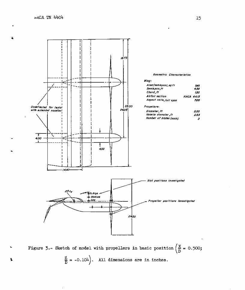
Drawings of the semispan model ad tables of geometric character-istics are presented in figures 2 and 3, and a photograph of the modelis presented h figure 4. The wing was constructed on a steel sparwhich held the two motor nacelles, the wooden blocks which fomned thewing contour, and the brackets which held the sliding flap in position.Several motor brackets were designed so that the nacelles could belocated in several vertical and chordwise positions with respect to thewing (fig. ~). In addition, there were several attaching points alongthe spar so that the outboard nacelle could be moved in order to pro-vide various amounts of propeller overlap. A drawing indicating theseoverkp positions is presented in figure 6._ —
The sliding flap rotated about a point 1.25 inches below the chordline at the bl-percent-chord station. The sliding ramp radius was
●
20 percent of the wing chord and was made tangent to the upper surfaceof the wing. ~ cavity which formed when.the sliding flap was deflected .was left unfilled. The resr flap, which was aFowler flap, had aClark Y airfoil section and a chord length equal to 40 percent of thewing chord, and when the flap was deflected, the flap leading edge was
located so that a slot gap of l~percent of the wing chord was main-
tained. The Fowler flap had.a deflection range from 0° to 70° ad wasfully extended for all deflected conditions (~f,F . 0 i~icates tht the
Fowler flap was retracted). The sliding flap had a deflection rangefrom 0° to ~“. Most of the tests were made with full-span flaps; how-ever, both the sliding and Fowler flaps could be segmented as indicatedin figure 3 to allow full deflection with the motor nacelles extendedthrough them.
Two alternate wing leading edges were provided. For tests withthe leading-edge slat, a leading edge was provided which gave the con-tour required to retract the slat as showz.by the solid lines in fig-ure 2. For all other tests the basic contour of the NAC!A4415 airfoilwas preserved as indicated by the dashed lines in figure 2.
The ground was simulatedby a ~- by 8-foot sheet of plywood. Theheight above the ground board is defined as the distance from the wingtrailing edge to the ground board. Thus, the position of the propellerwith respect to the ground board changes with flap deflection.

NACA TN 4404 5
.
The ground-board singlewas determined from the turning sngle whichw was measured for the test flap deflection out of the region of ground
effect; that is, the turning angle e plus the ground-bosrd amgle aadd up to roughly 90°. This condition simuktes the attitude of aVTOL airplane in hovering out of ground effect.
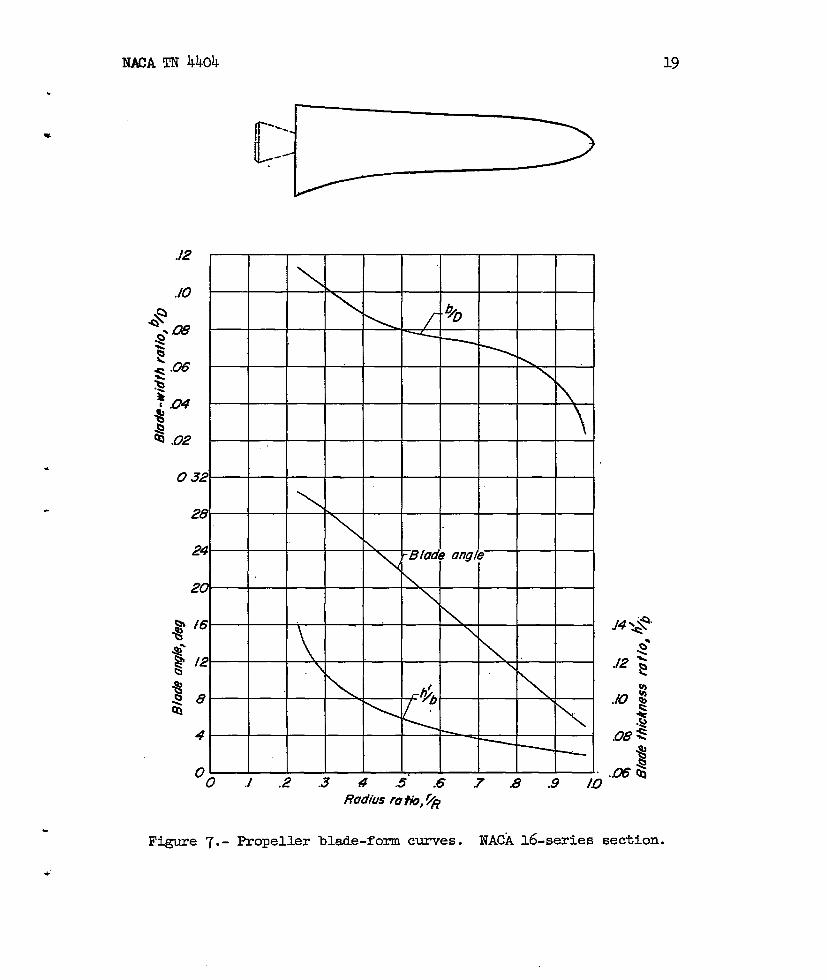
The propellers (geometric characteristics presented in fig. 7) weremodified versions of the propellers of reference 2 (three blades insteadof four blades) snd were made of balsa covered with fiber glass sad weredriven ly water-cooled variable-frequency electric motors operated inparallel from one variable-frequency power supply, which kept the motorspeeds matched to 10 rpm. The speed of rotation of each propeller wasdeterminedly a stroboscopic-type indicator which received the outputfrequency of small alternators connected to each motor shsft. Both pro-pellers rotated so as to oppose the direction of flow of the wing-tipvortex. During the tests the speed of rotation was maintained at approx-imately 5,800 rpn which corresponds to a propeller tip Mach numberof 0.54.
The motors were mounted inside altinmn-alloy nacelles by means ofstrain-gage beams so that the propeller thrust and torque could be meas-ured. The total lift, longitudinal force, and pitching moment were
. measured by a three-ccmponent strain-gage balance mounted below the endplate at the wing root.
b The investigation was conducted in a static-test facili@ at theIangley Aeronautical Laboratory. All data presented were obtained atzero forward speed with a static thrust of approximately 25 pounds ateach propeller. !l%isgave a disk loading of 8 lb/sq ft which is prob-ably somewhat below the level that would be used in most full-scaleapplications. Inasmuch as tests were conducted ina lsrge room (ref. 3),none of the corrections which sre applicable to wind-tunnel tests wereapplied.
RESULTS AND DISCUSSI~
Effect of Nunber of Propellers
A comparison of the turning effectiveness obtained with one andwith two propellers not overlapped is presented in figure 8. The chiefeffect of using only the inbosxd propeller is seen to be a laxge loss(up to 20 percent) inthrust-recovery factor (at a given turning angle)and a small loss in msximum turning angle. This result is in agreement
L with the data of reference 1 which also indicate a serious loss inthrust recovery for a doulle-slotted-flap configuration. Reference 4.,on the other hand, exhibited primsrily a loss in maximum turning angle*

6
when onlyflaps anddifferent
NACATN 4404
.
the inboard propeller was used on a model eqtipped with plainauxiliary turning vsnes. The reasons for these losses and the P;manners in which these losses present themselves are not
clearly understood; however, tuft studies of the flow around these modelsindicate that spanwlse flow develops at the edge of the slipstream whenthe slipstream impinges on the lower surface of the highly deflected
...”
flap system. The amount of this spanwise flow and the losses resulting “-therefrom increase with increasing flap deflection. When two slip-streams are parallel and tangent to each other, spanwise flow can developonly on their free sides. The losses in the turning processes wouldtherefore be expected to be lower with two propellers per semispan. .
Effect of Vertical Position of Propeller
Out of the region of ground effect, downward displacement of thepropeller greatly reduced the diving mcments inherent in this coru?igu-ration but also generally produced slight .~ossesin the turning angle(figs. gto U). As has been noted on previous configurations,the “ _reduction in the diving moments is almost entirely due to the directmoment of the thrust vector passing below the manent reference point.Little or no aerodynamic change is evident.
Reference 1 showed that lowering the thrust line generally reduced●
the losses in turning angle and thrust recovery usually encountered asthe ground is approached. From figures 12 and 13 of the present report ‘
it is seen that lowering the thrust line frcm ~ = 0.021 to := -0.104
resulted in some reduction in the losses experienced within the ground-effect region. However, further lowering of the thrust sxis toz-=D
The
the
-0.229 resulted in sizeable increases
( )lowest propeller position ~ = -0.229
D
(wing was very close to the ground ~ =
It should also be noted that the most
in these losses in general.. —
was found superior only when
)0.20 .
serious ground effects areencountered with the highest flap deflections (fig. 13). This conditionarises because the rea&fl.ap is more prone to flow separation when atthe high deflection angles as has been noted previously in reference 1.
In general the present investigation did not show as large a bene-ficial effect of lowering the thrust line as might have been expectedfrcm reference 1. This difference maybe due to a number of contributingfactors including the difference in ground-bosrd angles used and the fact 2that the flap system used in the present investigation is not as efficienta6 that of reference 1. v
7NACATN 4404 ,,
.
Effect of Extending Nacelles Through Flaps
~Inasmuch as the motor length was fixed, it was necesssry to segment
the flaps to allow for flap deflections when the motor was mounted inthe most resrward position. In order to demonstrate the effect of flapsegmentation, tests were made with the propeller in Chordwise Position
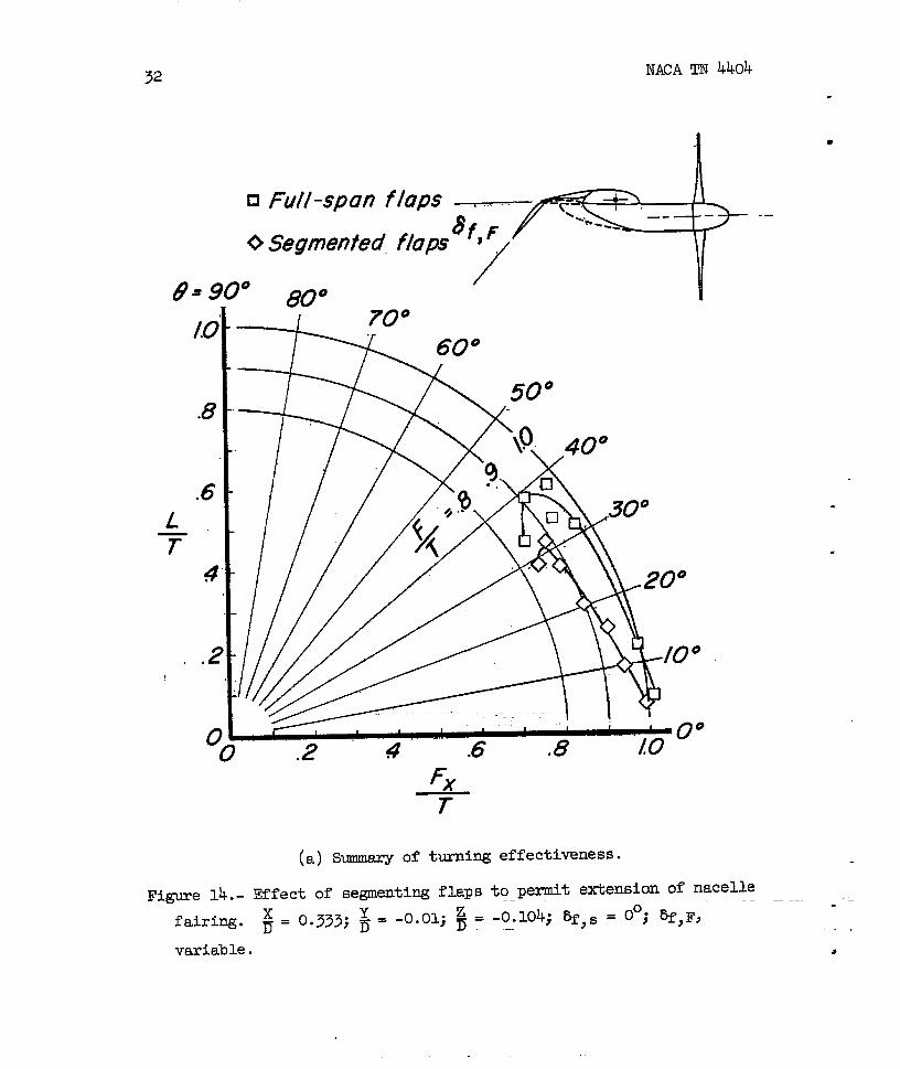
x- = 0.333 utilizing segnented and full-spa flaps. Figures 14 to 16Dindicate that segmenting the flaps results in a very large loss in hththrust recovery end turning angle. WS loss, of course, is to beexpected inasmuch as the flaps are carrying practical all the loadresulting frcxndeflecting the slipstream. Any cutout in the flap sys-tem will therefore allow some of the slipstream to pass through withoutbeing deflected and also large turbulent mixing losses will be encoun-tered at the ends of the flaps made by the cutout. The reductions indiving moment shown in figures 14 to 16 sxe a natural result of thereduced load carried by the flaps.
Effect of Chordwise Position of the Propellers
In general, chsmges in chordwise Position ~ ~ev ~tt~ effect. (figs. 17 to 26) on the slipstream deflection characteristics. Out of
the region of ground effect, rearward displacement of the propellers
- from ~= 0.500 to *= 0.333 produced an increase in turning angle
end thrust recovery throughout most of the flap-deflection rsnge(figs. 17 to 19), whereas a loss in turning amgle and thrust recoverywas noted at the larger flap-deflection angles when the propeller was
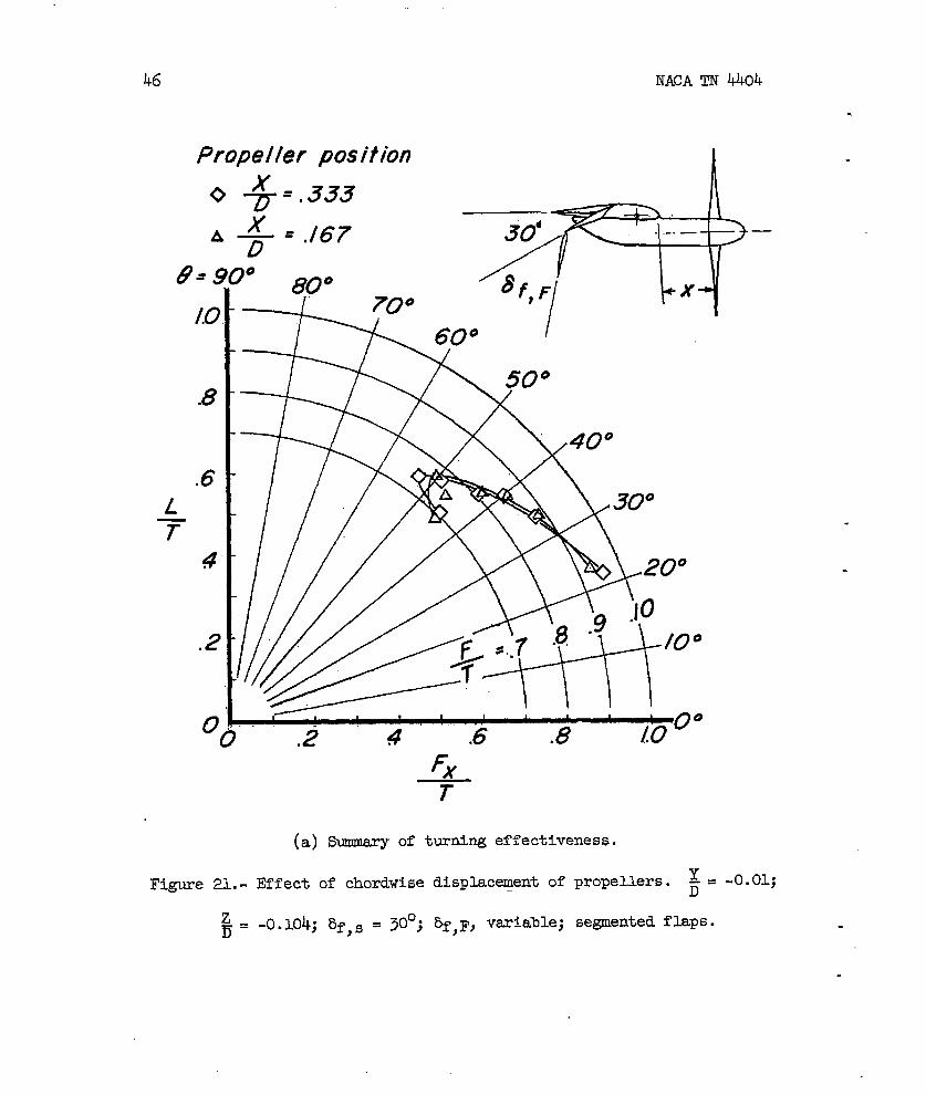
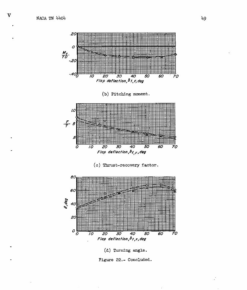
moved fsrther resx’wardfrom ~=0.333 to ~= 0.167 (fig. 22).
Chsages in diving mcment were, for the most part, insignificant.
The effect of chordwise displacement of the propeller on the aero-dynamic chsxacteristics of the model in the region of ground effect wasgenerally small and inconsistent. (see figs. 23 tO 26. )
Effect of Propeller Overlap
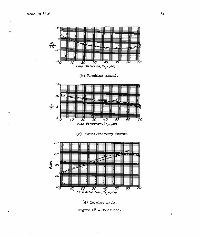
Figures 27 to 2S’present the effect of propeller overlap on theperfcmmance characteristics of the propellers and the aerodynamic char-acteristics of the model. Increasing the prope~er overlap to 0.208Dproduced increases in turning effectiveness on theIn the highest range of flap deflections; howeverj
m noticeable in the lower range of flap deflections.in overlap from 0.208D to 0.2glD did not produce a
order of 10 percentthis effect was notA further increasecorresponding increase

8 NACA m 4404
.
in turning effectiveness. The effect of overlap on pitching momentwas negligible. w’
As the propellers sre overlapped, however, the static-thrust effi-ciency of the propeller is reduced as shown in figure 30. Such a lossin efficiency is to be expected, of course, because as the propellersare overlapped they must each operate in the inflow or slipstream pro-duced by the other propeller. If the overlapping were csrried to thepoint that the propellers were Coadalj for instance (but the effi-ciency sti~ based on the sum of the individual disk sxeas), it wouldbe found that the efficiency of each would be reduced to 70.7 percentof their nonoverlapped value if the load were assmed to be equallydivided between them.
Figure ~ indicates that almost alJ.the loss was csrried on theinboard propeller. This loss in efficiency of the inbosrd propellerwas due pr~ily to a loss in thrust with overlap with only a smallincrease in torque (about 3 percent) appearing. Simultaneously theoutboard propeller exhibited only a small increase in both thrust (about4 percent) snd torque (about 6 percent). _Dwringthese tests the pro-peller rotational speed was maintained constant at 5,800 rpm.
..
The reason for these differences is not understood at present; .however, there csm be many contributing factors. For instance, refer-ence 5 indicates that the inflow velocities produced by the outboard(rear) propeller on the inboard propeller ,canbe appreciable even for - _the moderate emounts of overlap involved in these tests. The outbo~-d ‘--(rear) propeller, on the other hand, is also subjected to an inflowwhich is the slipstream of the inboard propeller. Measurements of theslQpstresm velocities on a propeller simiQr to the present one, however,indicate that the slipstream dismeter is appreciably smaller thsm thepropeller dismeter even 2 inches behind the propeller disk. The rearpropeller (outboard) then wouldbe subjected to the slipstream of thefront propeller over only psrt of the overlapped area. These inflowsprobably account for the losses in efficiency shown, and differences
.=
in these Mlows could account for some difference in the mount of losscarried on each propeller. Reference 6, oh the other hemd, indicatedequal loss on each propeller. Reference 6, however, also used oppositerotation of the propellers, whereas in the present tests both propelkrsused right-hand rotation. This difference praiuces a change in therotational component of velocity to which the rear propeller is sub-jected; thus, both the local blade amgle and local velocity to whichthe blades are sub~ected over part of the overlapped area are altered. .
The increase in thrust-recovery factor with overlap at the higherturning angles and flap deflections (fig. 29) and the loss in propeller #efficiency with overlap (fig. 30) tend to be canceling effects.

7NACA TN 4404 9
.
The ability of the propeller to produce thrust vsries as the two-
- thirds power of the efficiency; therefore, in order to compare theresults on the basis of constant power it is necessary to multiply theratios of lift to thrust L/T sad longitudinal force to thrust Fx/T,-
()
‘Y/D 2/3by as shown in figure 31. The average of the inbosrd
~Y/D=..ol ‘
and outbosrd efficiencies was used in the calculation. Fran this com-parison, based on constant power, it is seen that the effect of propelleroverlap is to reduce the available resultant force at alJ but the veryhighest turning sagles where sane gain on thrust recovery is still “evident.
This comparison is made on the basis of constant propeller diameter.If the design conditions fix the span of the wing, it is possible to
increase the resultant force for a given power by overlapping largerprope~ers which will permit a gain in net disk srea which wil.1,in turn,produce a gain in thrust. However, to maintain the same turning anglethe wing and flap chord would also have to be increased proportionallyto the increase in propeller diameter.
.Effect of Position and Deflection of a Leading-Edge Slat
b Reference 7 indicated that a large-chord leading-edge slat could,to some extent, counteract the diving-nmnent characteristic of deflectedslipstream configurations, and reference 8 showed that such a slat woulddelay wing stall in the transition speed rsmge. Therefore, a 30-percent-chord slat mounted in several vertical positions was investigated in theregion of ground effect and the results are presented in figures 32 to 37.
The propellers were mounted at ~ = 0.333 and ~= -0.104 for all slat-
position tests.
The tiediate effect of the addition of the slat when deflected soas to reduce the diving mcxuentjwas a significant loss in thrust-recoveryfactor and turning angle. In general a slat deflection of 0° producedthe best thrust recovery and highest turning angles although these valueswere seldcm better than the slat-off values and this slat deflection onlyproduced small reductions in the diving r.uanents.
Propeller Static-Thrust Efficiency in &ound Effect
The variation of the static-thrust efficiency of the propellers with.height above the ground and slat deflection is presented in figure 38 fortwo flap configurations. In general the outboard propeller showed little
..w

10 NACA TN 4404
.
change in efficiency with height above the ground; however, the inboardpropeller showed a slight loss in efficiency at intermediate heights “- ~and a gain in the positions closest to the ground. This loss in effi-ciency at intermediate heights is unfortunately coincident with the lossin thrust recovery at these heights and for the case of constant powerwould tend to increase the loss in resultant force available to supportthe airplane in hovering at these intermediate heights.
Effect of Nacelle Size
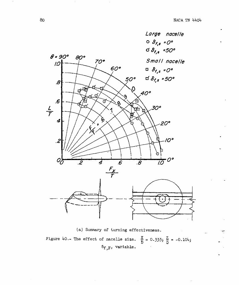
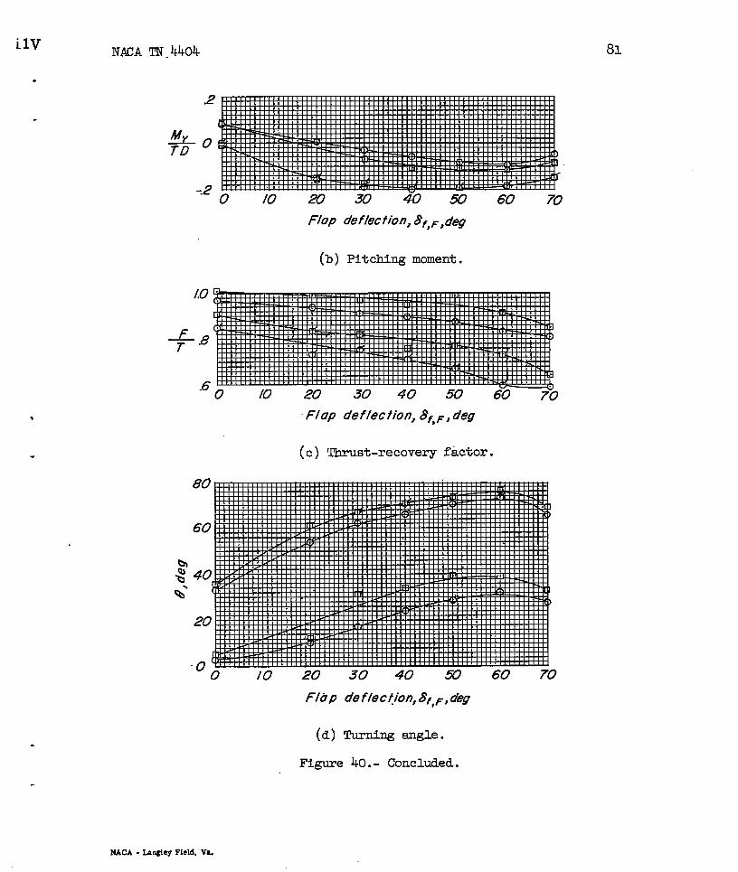
The majority of the data of this and previous investigationswereobtained with small nacelles which might represent a turboprop instal-lation or a fairing over the power train from a remotely mounted engine.Use of reciprocating engines would require much larger nacelles. Inorder to investigate the effect of nacelle size, balsa-wood fairings(shown in fig. 39) were added to the model to simulate a reciprocatingengine installation.
The results of the investigation of the effect of nacelle size(fig. 40) show approximately 5 to 10 percent loss in turning effective- ~ness when the larger nacelles are used. This loss appeared to be asso-ciated with flow separation at the juncture between the wing and nacelle
.—
on the lower surface, particularly on the rear tapered part of the.
nacelle. Attempts to regain some of these losses by the use of largefillets were only partially successful. These losses, in addition to 4the lower ratio of thrust to weight, pkce present recipro~tiu e=inesat a considerable disadvantage to turboprop engines for use on VTOLaircraft.
CONCLUSIONS
An investigation of the effect of propeller position and overlapon the slipstream deflection characteristics of a model eqtipped witha sliding and a Fowler “flapindicates the zollowing conclusions:
1. Iarge reductions in diving moments were obtained by loweringthe thrust sxis. However, these reductions were almost entirely dueto the direct moment created by displacing the thrust vector below themcment reference point. Vertical and chordwise changes in propellerposition produced little or no change in the aerodynamic characteristicsout of the region of ground effect. In the region of ground effect,lowering the thrust axis about 10 percent of the diameter produced somereduction in the adverse effects of the ground. J
w

NACA TN 4404 U
.
2. In the highest range of flap deflections, propeller overlap
3 produced a significant increase in thrust recovery while producing nochange at low and intermediate deflections. However, as the smount ofpropeller overlap was increased, the static-thrust efficiency of theinboard propeller decreased while the efficiency of the outboard pro-peller remaimed nearly constant, the net result at constant power beinga reduction in resultant force due to loss in propeller efficiency atlow and inte?nnediateflap deflections and only a small gain at highflap deflections.
3. The thrust recovery with inbosrd propeller alone was much lowerthsn with two propellers.
4. Se~enting the flaps to petit rearw~d extension of the nacellefairing great~ reduced both the thrust recovery and the turning angle.
5. The addition of a leading-edge slat caused a significant reduc-tion in thrust recovery and turning amgle at slsk deflections needed toreduce the diving mcsnentsappreciably.
6. Increasing the nacelle size to stiukte that required for recip-rocating engines reduced both the turning singleand thrust recovery.
Langley Aeronautical Laboratory,w National Advisory Comittee for Aeronautics,
Langley Field, Vs., August 12, 1958.

12
REFERENCES
NACA TN 4404
.
1. Kuhn, Richard E.: Investigation of the Effects of Ground Proximitysnd Propeller Position on the Effectiveness of a Wing With Lsrge-Chord Slotted Flaps in Redirecting PiopeUer Slipstreams Downwsrdfor Vertical Take-Off. NACATN 3629, 1956.
2. McLem~re, H. Clyde, and Cannon, Michael D.: Aerodynamic Investiga-tion of a Four-Blade Propeller Operating Through an Angle-of-AttackRar@e fi~o” to 180°. NACATN 3228, 1954.
3. Kuhn, RichardE.: Investigation of Effectiveness of a Wing EquippedWith a 50-Percent-Chord Sliding Flap,-a 30-Percent-Chord SlottedFlap, and a ~-Percent-Chord Slat in Deflecting propeller Slip-streams Downward for Vertical Take-Off. NACATN 3919, 1957.
4. Kuhn, Richard E., and Draper, John W.: @ Investigation of a Wing-Propeller Configuration Ihploying Large-Chord Plain Flaps audlarge-Dismeter PropeDers for Iaw-Speed Flight and Vertical Take-off. NACA TN 3307, 1954.
5. Castles, Walter, Jr., and De Ieeuw, Jacob Henri: The Normal Compo-nent of the Induced Velocity in the Vicinity of a Lifting Rotorand Sane Examples of Its Application. NACA Rep. 1.184,1954.(SupersedesNACA TN 2912.)
6. Kuhn, Richard E., and Draper, JohnW.: Investigation of the Aero-_ic characteristics of a Model Wing-Propeller Cmlbination andof the Wing and Propeller Separately at Angles of Attack up to 90°.NACA Rep. 1263, .1956. (SupersedesNACA TN 3304 by Draper and Kuhn.)
7. Kuhn, Richard E.: Investigation at Zero Forward Speed of a Lead.ing-Edge Slat as a Longitudinal Control Device for Vertically RisingAirplanes That Utilize the Redirec~ed-SlipstreamRrinciple. NACATN %92, ~956.
8. Kuhn, Richard E., .andHayes, William C., Jr.: Wind-Tunnel Investi-gation of Effect of Propeller Slipstreams on Aerodynamic -acter-istics of a Wing Eqtipped With a 50-Percent-Chord Sliding Flap anda X-Percent-Chord Slotted Flap. NACATN 3918, 1957.

● r
/,’
F
P----------,
-1 “T8#/#,T
T
/?
Figure 1.- Convention
.
used to define positive sense of forces, moments, and angles.

~,;—..-j
4.60
“i
-.// ——-.:=
- *a.— —
150, I I I 2.88 I
I----59 4 “–”—”—“-,:,<:/6
Figure 2.-
-i.
Gmxuelmic
1
%—0.43.Im
1.OEuL.b40e.lsoE.IE.25.tii.xm
—
. 0.351“;1:!2l.m1A161.CQD
?
T{’\\\\~ ‘\ ‘1,4m \ \
\\
\\
\
\\
‘\\A,
ckmacterj.sties of, wi.ng section. KU dimensions are in inches.
.
15
.
LI
IIIII
t+
------t --1-
7L---:::/
I
1
Un&fIected for festslWf fb extended naceffes;
E
\
I
_ --<-------
4.001-.
~ _----_;::
III1
I
iIIIIIII---
--4---t
IIII1IIII
---I--—----
I
I
[II
II
I
I[[
LI -.II tI 4W
II
5
5!5
Geometric Characteristics
Wing:
Areu(ssmhpan), sq ft 348.9mhpan,ft 458
Chord, ft L&U
Airfoil section N.4CA 44i5
Aspect rat fo, fufIswn 766
70 Propellers:
Diameter, ft
Nacwile diameter, ft
Num&r of btades(eochJ
2.(W
.0333
SIatpasifions Investigated
25CS’
Propeiler pasltions ilwestfgoted
Figure 3.- (Sketch of model with propellers in basic position ~ = O.~;
z)
-= -0.104 .D
All dimensions sre in inches.

16 NACA TN 4404
.
u
L-96x5
Figuxe 4.- Model installed in a static-test faciuty at the Langleyz
Laboratory. ~ = 0.500; ~ = ‘O.O1; 5 = ‘“”a”

NACA TN 4k4
.
vertical posltlons
.
.
17
Longii%dlnol ~itiom
v
,wcelle extendsdthmxgh fbp S)WtSM
I
.
Figure 5.- Sketches of model showing vertical and chordwise positionsof propellers. All dimensions are in inches.

NACA TN 4404
.
—
/-----’
4
—1440—
..? 5fr
— 12,00 —
. .
— IOCG41
I/7$
i
6
Vorlable
I
..>-. e 1
—
o
\
I
I 2 00
El‘
‘ Zm
m..Y. .–,.. ..
,—-------- -- “ -------= --=-
XiaR
+=./25
w
@
Y. .
-— --- - --- —-.-— - - --- -----
F1 .
+.208
Y
*
----— ---—---- -—-- -—
....’
+=.29/
.
Figure 6.- Sketches of model showing propeller-overlap configuration.All dimensions are in inches.
NACATN 4404 19
I I I Iv ‘1 I I Ixt
$Q’
4
00 J .2 .3 4 .3 .6 ? .8 .9 10
Radius ram, $jR
Figure 7.- Propeller blade-form curves. NACA 16-series section.

20 NACA TN 4404
Inboufd propeller
~f,s
)0 80°
On/y
o 8f, # =0°
a &# =50°
Both propellers
c1 &# =0°
d 8f,# =50°
+
(a) Summary of turning effectiveness.
Figure 8.- Comparison of twning effectiveness obtained with one andx
two -propellers. ~ = 0.500; * = -0.01; ;= -0.104; 5f,F, variable;
full-span flaps.— —.
.
d

NACA TN 4404
.
21
.
My
TO
2
0
-.2
c’ /0 20 30 40 50 “60 70
/%p def Iection, A’C~, deg
(b) Pitching mcment.
0 10 20 30 40 50 60 70
Flop deflection, 8<~1 deg
(c) Thrust-recovery factor.
80
60
40
20
‘O /0 m 30 M ~ 60 70
Flap defection, 8f,~,deg
(d) Turning angle.
Figure 8.- Concluded.
22 NACA TN tiOh
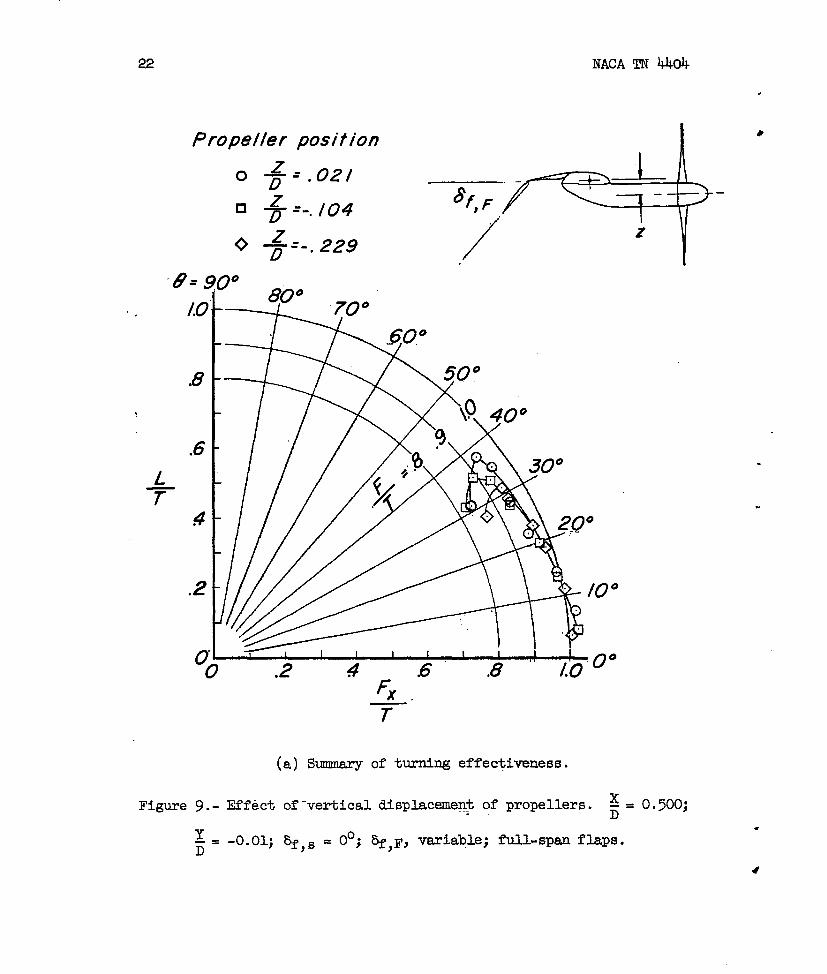
Propeller position
z—’.02/‘D
‘% =-. /04
0; —=- 229.
L-T
00
.
●
.
“
Fx—’
T
(a) Sumary of turning effectiveness.
Figure 9.- Effect o?-vertical displacement of propellers. ~ = 0.500;. D
Y-= -0.01; &f= = ble ● full-span flaps.OO; &f,F> v=ia. #D

NACA TN 4404
.
ftap deflection ,%f, ~, deg
(b) Pitching m~nt.
.
.
23
Flop de flection,8f, rJdeg
(c) Thrust-recovery factor.
Flap d&f/ection,Ff~P dw
(d) Turning emgle.
Figure 9.- Concluded.

24 NACA TN 4404
Propeller position I
~.
(a) summary of turning effectiveness.
Figure 10.- xEffect of vertical displacement of propellers. - = 0.500;D
Y_ = -0.01; bf,s = 30°; bf,F, variable; full-span flaps.D
.
Y
.
.

NAC!ATN 440425
Flap de flection,~f, ~, deg
(b] Pitching mcment.
.
.o /0 20 30 40 SO 60 70
Flap deflection,8f, ~, deg
(c) Thrust-recovery factor.
Flop de flection>f, ~, deg
(d) Turning amgle.
Figure 10.- Concluded.
26 NACA TN 4404
.
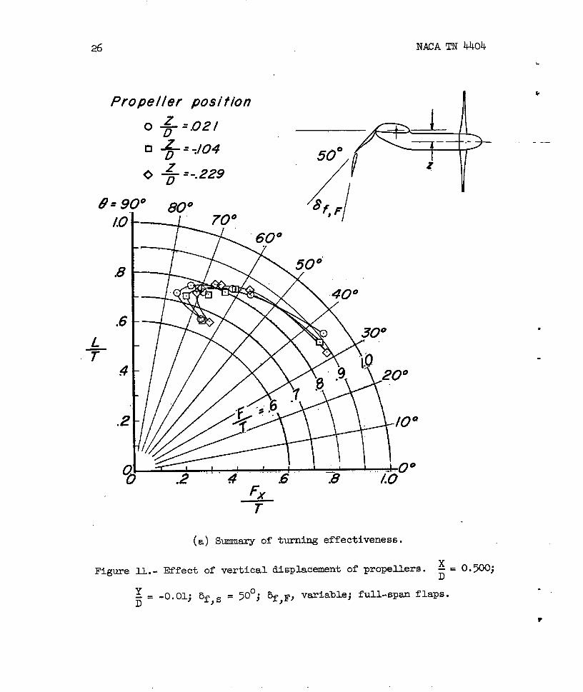
Propeller positionI
k
1
50°
/ /
-+
1080°
(a) Summary of turning effectiveness.
Figure 11.-X
Effect of vertical displacement of propellers. - = 0.500;D
Y-= -0.01; bf,~ = 50°; ~,F, vuiable; full-sp= flaps.D

NACA TN 440k 27
F-7
.
.
s’b%’
o 10 20 30 40 50 60 70,Flop de f/ection,8< ~, deg
(b) Pitching moment.
o 10 20 30 40 50 g 7tiFlop deflection,~f ~ deg
I.
(c) Thrust-recovery factor.
/%7p d(?f/..CtkV?,8f,6egeg.
(d) Turning angle.
Figure il.- Concluded.

Propeller position7 I
IL
,8
.6
4
.2
G
~= $
LT
1 1 1 I I I , I 1 1 r. .2 # .6 .8 ‘ /go”’oo
(a) Summsry of turning effactiveness.
12.- Effect of vertical displacement of propellers inFigure
of ground effect. ~ = 0.500; ~ = -0.01; % s = 50°; bf F) )
ground-bosx’dangle, 32°; full-span flap; h/D, variabti.
.
.
the region
= @;●
✎

NACATN 4404 29
A#
(b) Pitching mcment.
(c) Thrust-recovery factor.
(d) Turning angle.
Figure 12.- Concluded.
30 NACA TN 4404
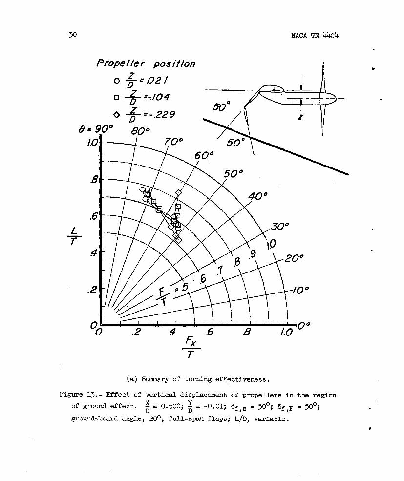
Propeller posif~on
LT
Figure
/.0
B
.6
#
.2
z -.02/OT.
❑ .+- =7104
z—=-.229‘D7° 80°
50°
60°
.2 4 -.6 .8 /.0 “=
(a) Sumary of turning effectiveness.
13*- Effect of vertical displacement of propellers in the region
of ground effect. ~ . 0.500; ~ . -0.01; bf,8 = 50°; bf,F = 50°;D
ground-bosrd angle, 20°; full-span flaps; h/D, variable.
.
.

NACAT!N 4404
.
31
A# Im
(b} Pitching moment.
(C) Thrust-recovery factor.
(d) Turning angle.
Figure 13.- Concluded.
32 NACA TN 4404
8
n Full-span f bps .. .
0 Segmented f/ops
.8
.6L—’T
4
G-., - \ I v’, .,00°
.2” 4.68
(a) Smmary of turning effactiveness.
Figure 14.- Effeet of segmenting flaps to permit extension of nacelle
fairing. ; = 0.333; ; = -o.o~; # = -9”104; m,s = O“j ~,F>
variable.
.—
-.J

TNACA TN 4404 33
.
.
.
>
b
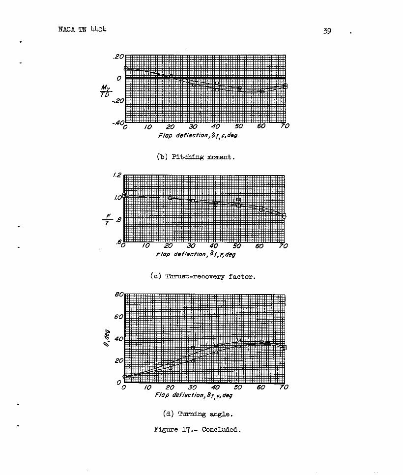
MyTD
Flap deflect ion, 8 f, F, deq
(b) Pitching moment.
F/up deflecfion,$f,F,deg
(c) Thrust-recoveqy factor.
80
60
40
20
00 /0 20 30 40 50 60 70
F/op d?f/i9CfiOn,8f,F,deg
(d) Turning angle.
Figure lk.- Concluded.
34 NACA TN 4404
.
~.:
/.0
.8
.6L
74
.2
0i
I*
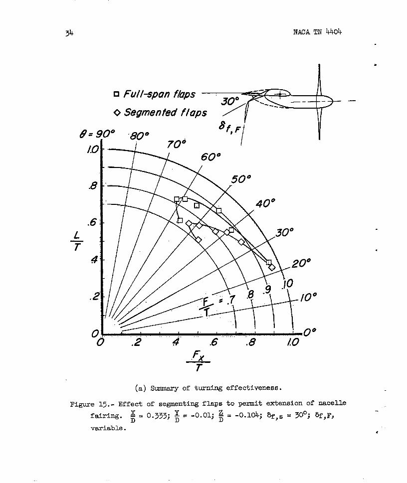
Fukspcm fh’s l\-+> –
Segmented flaps
‘f F80° t i
i ~~o I
(a) Summary of turning effectiveness.
Figure 15.- Effect of segmenting flaps to permit extension of nacelle
fairh.g. ~ = 0.333; ~ = -0.01; ~ = -0.104; %,s = X“; ~,FI
variable.●

NACA TN 4404
Flap defection, ~f, F, deg
(b) Pitching mcaent.
F-7
Flap de f/eCtiOn,8f ,F, de9
(c) Thrust-recovery factor.
(d) Turning angle.
Figure 15.- Concluded.
35
Flap deflection,af, F, deg

36 NACA TN 4404
n
“o
Fu//–spun
Segmented
8“ 90° 80°‘9
fA7ps
f/aps
70°
.
.
FxT
(a) s~ of t~ning effectiveness.
Figure 16.- Effect of segmenting flaps to permit extension of nacelle
fairing. Y z—
~= 0.333; ~= -0.01; ~= -0.104; bf,s = 50°; ~f,F,D
vsxiable.*

NACA TN 4404
.
Flap 02?f/ection, ~f, F, deg
(b) Pitching mcment.
37
Flop deflection, af, F, deg
(c) Thrust-recovery factor.
Flop de flection,af, F, deg
(d) Turning amgle.
Figure 16.- Concluded.

NACA TN 4404
?ropeller position
.
.
x’27 = .500
8f ~ —= .333 #
‘I%!+&
70°
6(7°
en o
.8
.6
4
.2
a! ‘— ‘ 1
o’.2”4”.6”-.8””-1 I I 1 1 I i “0°
!0
Figure 17. -
3=
F-T
(a) Smmary of turning effectiveness.
Effect of chordwise displacement of propellers. ~ = -0.01;
-O.1O4; ~,~ = OO; ~,F, vsriable; full-span flaps.
.
‘
.
.
NACA TN kklk
.
.
Flap deflection, 8 f, F, deg
(’b) Pitching mcment.
.
.
.
Flap deflection, ~f, 4 deg
(c) Thrust-recovery factor.
39 ●
Flop deflect ion, 8 f, F, deg
(d) Turning angle.
Figure 17.- Concluded.

40 NACA TN 4404
x.= .500‘D
x =,333n ‘~
8.9 p80°
‘“” 7+0
30” —
60°
.8
.6L
74
,2
(.) Summary of tming effectiveness.
Figure 18.- Effect of chordwise displacement of
z- = -0.104; bf,s = 30°; ~,F, variable;D
propellers. ~ = -0.01;D
full-span flaps.
,
.

lJACATN k404
.
A.#
.
41
Flap deflection, 8 f, f, deg
(b) Pitching manent.
Flap defection, 8f, ~, deg
(c) Thrust-recovery factor.
F/op deflection, 8f, ~, deg
(d) Turning angle.
Figure 18.- Concluded.

42
Propeller positionox — =.500
Dx—=.333
‘D
F--
(a) Summary of turning effestiveness.
Figure 19.- Effect of chordwise displacement of propellers. ~ = -0.01;
z-= -0.104; af,~ = 50°; @,F, veriable; full-span flaps.D
.

NACATN 4404
.
.
.
.
%’-Q%’
Flap tfeflecfion,8f,F, deg
(b) Pitching moment.
Flop deflection, af, F, deg
(c) Thru6t-recavery factor.
‘O /0 20 30 40 50 60 70Flop de f/ection,8f, F, deg
(d) Turning angle.
Figure 19.- Concluded.
43

44 NACA TN 4404
●
Propeller pos I’f ionx=
‘z-.—
.8
.6
.4
.2
.2 4 .6 .8 Lo ‘u
(a) s~ of turning effectiveness.
-.Figure 20. - Effect of chordvise displacement of propellers. ~ = -0.01;
JJ
z-= -,0.104; 5f,B = OO; ~,Fj variable; segmented flaps. ,D

NACA TN 4404
.
.
Flap deflection,af, ~, deg
(b) Pitching moment.
.
.Flap deflection, Bf, F. deg
(c) ‘lhrust-recoveryfactor.
45
Flop deflection, ~f, F, deg
(d) Turning angle.
Figure 20.- Concluded.
46 NACA TN 4404
Propeller position I
.8
.6L
—
F’-7
(a) Summery of turfing effectiveness.
Figure 21.- Effect of chordwise displacement of propellers. ~ = -0.01;
zD=
-0.104; 5f,~ = 30°; %,F, vsxiable; segmented flaps.

.
.
47
A’#
Flap deflection,~f ,F, deg
(b) Pitching mcment.
.
.Flap defleciion,~f, F, ~eg
(c) Thrust-recovery factor.
-o 10 20 30 40 50 60 70
Flop de flection,~f, F, deg
(d) Turning angle.
Figure 21.- Concluded.

48 NACATN 4404
9=9(
/.0
,8
.6
.2
0(
Figure 22.~
z-=D
~ + =.333
Ax 500—=./67
80°
‘o&
70°
/
.
.
.2 4 .6 .8 booF’T
(a) Summary of turning effestiveness.
Effect of chordwise
-0.104; 8.Q = 50°;
displacement of
~,F} v~iable;
propellers. ~ = -0.01;
segmented flaps..
.
v
.NACA TN 4404 49
.
Flap deflection, ~f, 6 deg
(b) Pitching mcment.
.
.0 /0 20 30 40 50 60 70
Flop de flection,8f, F,deg
(c) Thrust-recovery factor.
Flap de flection,~f, F,deg
(d) Turning angle.
Figure 22.- Concluded.

50 NACA TN 4404
.
Propeller position
o
ut9=9,
1.0
.8
.6L
7’4
,2
+=.500
x—. 222
.2
30°
1~ I I I I 1 t I,0 0°
.8 .4 .6F-T
(a) Summary of turni~ e.ffectiveness.
Figure 23. - Effect of chordwise displacement of propellers
region of ground effect. Y-= -0.01; ;= -0.104; bf ~ =o
D
bf,F = 20 ; a= 32°; full-spa flaps; h/D, variable:
in the
500;
.
.
.
—

NACA TN 4404
.
.
(II) Pitching mcment.
-..
(c) Thrust-recovery factor.
(d) Turning angle.
Fi~e 25.- Concluded.

52 NACA TN 4404
‘8=9[G
.8
.6L
74
.2
‘o
.
.
.
position
o += .500
Q ~ =.33350°
D/0 80°
//-’&//4”---1 1 I 1 1r— , , c
1
.2 4 .6 .8 Lo ‘“
+
(a) Sanmary of turning effectiveness.
Figure 24.- Effect of longitudinal displacement of propellers in
the region of ground effect. ~ = -0.01; ~ = -0.104; bf,s = 50°;
bf,F = 50°; a = 20°; full-span flaps; h/D, variable.
.
.

NACA TN kkti
.
.
53
hu
(b) Pitching moment.
.
+
(c) Thrust-recovery factor.
(d) Turning angle.
Figure 24. - Concluded.

54 NACA TN 4404
.8
.6L
T4
xor ‘ .333
Ax—=./67D
)0 800
?%2?0 60
.
.
.
.2 4 .6 .8’ 10=”FxT
(a) mmmlm’yof turning effectiveness.
Figure 25.- Effect of
of ground effect.
a = 40°; 6egmented
chordwise displacement
Y-= -0.01; ;= -0.104;Dflaps; h/D, vsriable.
of propellers in the region
~f,s = ~OO; 8fjF = 20°;--
.

NACAT!N tik
.
55
.
A#
.
.20
0
.20
-.40
%
(b) Pitching moment.
/.2
/.0
+.8
.60.20 40 .60 .80 i!!
(c) Thrust-remvery factor.
2-b
%’
+
(d) Turning angle.
Figure 25.- Concluded.
co

NACA TN 4404.
.
x— = .333‘DAx.
D “167= 90° 80°/.0
.8
q’–,2’;’.6:m8 , ,0 0°. .f--
7-
(a) Summsry of turning effectiveness.
Figure 26. - Effect of chordwise displacement of propellers in the
region of ground effect, ~ = -0.01; ~ . -0.104; bf s = 50°;>
%,F = 50°; al= 20°; segmented flaps; h/D, variable.
.
.
.
—
.
.

v
T
MICA TN 4404
.
.
.
.
.
+$
(c) Thrust-recoveryfactor.
57
(d) Turning angle.
Figure 26.- Concluded.

Propeller position
.0 Y–=70/DY
❑ -T=’”~25~Y — = .208D
,00
,.
80°
.
.
Fx
‘T
(a) Smmsry of turning effectiveness.
Figure 27.- Effect of propeller overlap. %,B = OO; 8f,F, variable;
ftil-span flaps.
.
.

NACA TN 4404
*
.
Flap deflection,~< ~, deg
(b) Pitching moment.
F-7
. Flop de flech’cm,~f, j ,deg
(c) Thrust-recovery factor.
t?
:’
Flop deflection, af, F, de9
(d) Turning angle.
Figure 27.- Concluded.

60 NACA TN 4404
Y—=.125‘o
0+ .208f-=.291?
{
-$-.
30°
/F
—- —
1?‘8f,F/
F+
,
.
.
.
(a) Smmary of turning effactiveness.
Figure 28.- Effect of propeller overlap. ~f,s = 300; 6fF, variable;
full-span flaps...
.
NACA TN 4404
.
.
A+
Ffap deflecfionl af, f,deg
(b) Pitching moment.
.
.
80
60
61
Flap de flection,”$f, F,deg
(c) Thrust-recovery factor.
Ffop def~ec~ion, 8~, F,deg
(d) Turning angle.
Figure 28.- Concluded.
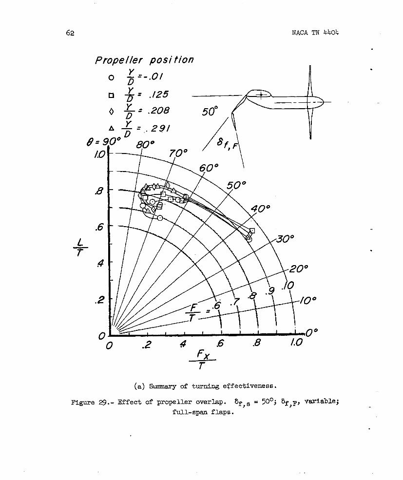
62 NACA TN 4404
Propeller posi tim no Y
– ‘-.0/D
.
.
Y
208 500,*❑ T = “’25
Yo 77’
(a) summaryof turning effectiveness.
Figure 29.- Effect of propeller overhp. 5f,6 = 50°; ~f,F, veriable;
full-spareflaps.
—
.

NACA TN 4404.
.
A’#
63
.
.
/2
Lo
.8
.6
Flap o’eflection,8f, ~,a’eg
(b) Pitching mcment.
Flop deflection, 8f, F , deg
(c) Thrust-recovery factor.
s’%%’
Flap de flection,8f, ~, deg
(d) Turning angle.
Figure ~. - Concluded.

64NACA TN 4404
.
.
Outboard propeller
d #f,# =0°
d +* ’30°
6 8;*Z5O” “#
Lo— .
T.8
Y/o
~Y/D=-,ol
.6
.4
2
00 .05 ./0 ./5 ,20 ,25
Figure 30.- Variation of average efficiency of propellers with overlap(averaged over @,F range).

vNACA TN ~~
.
.
.
65
0
❑
0
A
$ =-.0/
+ =./25
+=.208
+ =.29/
30°
,.
(71 r 1 I I I I I f I I f)”
-o .2 4 .6 .8 /0 w
Figure 31.- S~ or turning effectiveness based on constant power.
~f,s= S*O.

66
slot deelection, &/a@e9 1
R= 9
/.0
.8
.6
4
.2
0
Figure
7
● Slu f refruc tedo -//.5❑ -20
0 -30
)0 80° i
) .2
(a)
!4 .6 .FxT
8 10 w
Summary of turning effectiveness.
of slat deflection in low position. ~f,s. ~o;
s 0,333j ~ s .0.104; a s 32°; ~, variable.
.
.
.

NAM TN 4404
.
.
.
.
b
*
%’
.
-%
(c) Thrust-recovery factor.
o .20 40 .60 .80 Lm @
+.
(d) Turning angle.
67
I,.Figure 32.- Concluded.
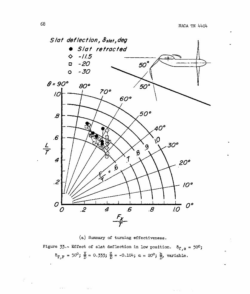
68 NACA TN 4404
Slut def Iection, &faf, deg● S/0 t re trac ted n
.8
.2
00
0 -//.5c1 -200 -30
180° t
.2 4 .6 .8 [0 “Fx
(a) Summary of turning effectiveness.
Figure 33.- Effect of slat deflection in low position. bf,s = 500;
5f,F = 50°; ~= 0.333; ~= -0.104; a= 20°; ~, variable.
.
.
.
.
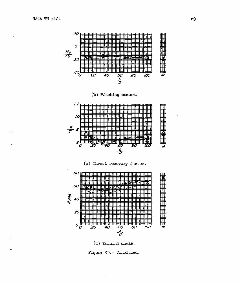
NACA TN 4404.
69
,
.
.20
0$
-.20
- An
(b) Pitching moment.
+
(c) Thrust-recovery factor.
(d) Turning angle.
Figure 33.- Concluded.

70 MICA TN 4404
.
Slot deflection, &lQt ,deg● S/0 t f e trac ted
“gttixx
.6L
7!4
.2
\
>-
“0 .2 4 .6F~T
* 0°.8 .
(a) Summary of turning effectiveness.
Figure ~. - Effect of skt deflection in middle position. ~f,s = 500;
%, F= 200; ;= 0-333; fi=-0*104; a= 320; & ‘aiabl-e”
.
.
.

NACATN 4404
.
71
.
-%
(b) Pitching moment.
F7.
(c) Thrust-recovery factor.
~.o 20 40 .60 .80 [W
+
(d) Turning angle.
Figure ~.- Concluded.

72 NACA TN 4404
Slat deelection, &10~,de9
● S10 t re trotted /
.
.
(a) Smmary of turning
Figure 35.- Effect of slat deflection
effectiveness.
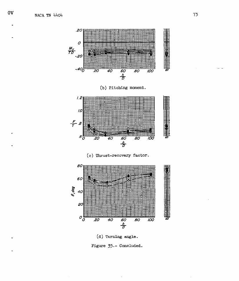
in middle position. ~f,s = 500; -
5f,F = 50°; ~= 0.333; ~= -0.104; u= 20°; ~, variable. —.
Ov
.
.
.
NACA TN 4404
+
(b) Pitching mcment.
73
+
(c) Thrust-recovery factor.
I
‘o .20 40 60 .80 IUO
%
(d) Turning angle.
Figure 35.- Concluded.

74
S/et def /ect ion, 8SW,deg
0 80°
NACA TN 4404
.
II
F“T
(a) Smmnary of tuning effectiveness.
Figure .36.- Effect of slat deflection in high position. ~f,s. PO;
32°; ~, variable.~f,F = 20°; ~ = 0.533; := -0.104; a=
.
.

NACA TN 4404
.
75
.
A#
(b) Pitching moment.
.
.
/.2
Lo
.8
.6
+
(c) Thrust-recovery factor.
+
(d) Turning sngle.
I“09
Figure 36.- Concluded.

76 NACA TN 4404
S/at deflec ti’on, &Oj ,de9● Slut retructed
.8
.6L
74
.2
o -20❑ -100 0A 10v 20h 30
/
60”
‘xx ,0°
.8
(a) Sunmary of turning effectiveness.
Figure 37.- Effect of slat deflection in high position. ~f,s = 500;
bf,F = 50°; ~= 0.333; ~= -0.104; a= 20°; ~, variable.
.
.
.
.
.—
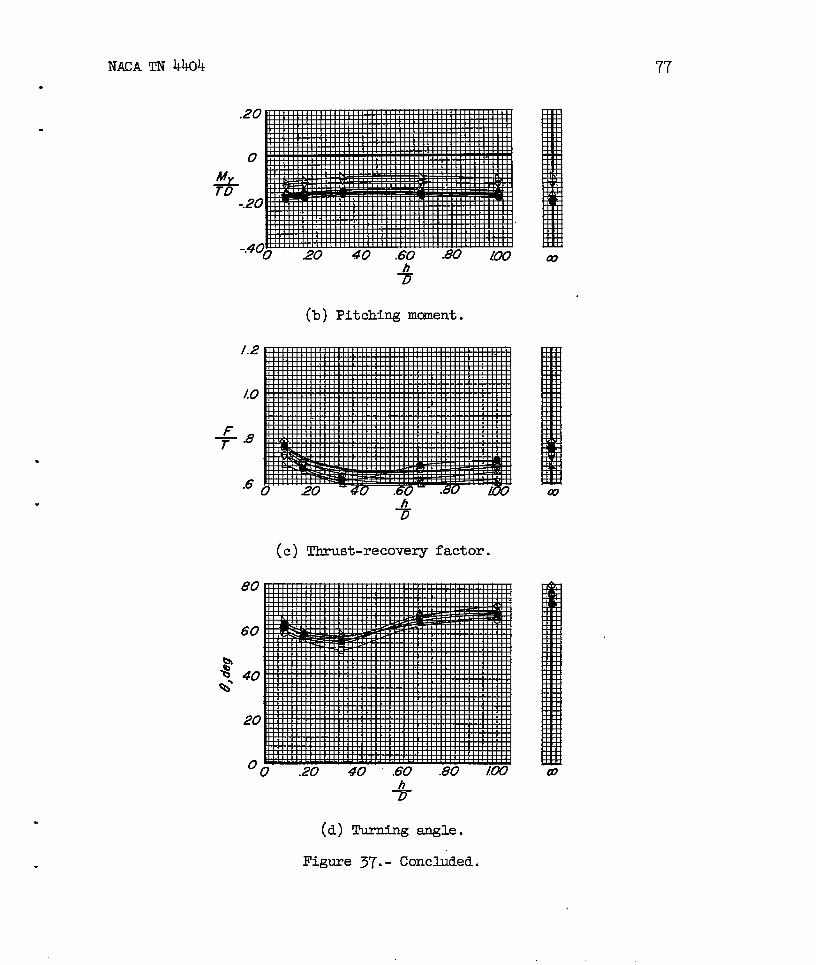
NACA TN 4404.
(b) Pitching mcsnent.
.
.
+8
.6
(c) Thrust-recovery factor.
7’7’
(d) Turning angle.
Figure 37.- Concluded.

(a)
(h)
‘iEEEfi3
W“ .
ti, s= ~“; %,F= 200-
(d) slat in low -positlon- %,s =500; +,F=~”.
Figure 38.- Effect of ground proxhnlty on propelkw
tions and flap configurations.
< .
static-tbrUSt efficiency
x z-=0.333; ~= [email protected]
-103
, .

NACA TN ~ok
Figure 39.- Model with large naceldes. L-96617
8=!/.G
.&
.6
L7
4
.2
G
7° 80”
%“ 60°
Large
0 4*S
NACA
nacelle
=0°
=50°
Smc7/1 nacelle
,
.
FXT
——. — I —.. —
_______
(a) sunmary of tuning effectiveness.
Figure 40.- The effect of nacelle Gize. 5 = 0.333; ~ . -0.10+;D
.
.
.
.
bf,F, variable.
iIV
e
NACA TN.4404
.
2
“o
.2
10
+.8
.6
0 /0 mF/up
(b)
.30 4“0 50 60 70
de f~eci’ion, ~f,F,@
Pitching moment.
Flop deflection, 8f,F, o’eg
(c) Thrust-recovery factor.
F/up deflection, &f,F, deg
(d) Turning angle.
Figure 40.- Concluded.
NACA - Lmgiey Field, Va.