nationaladvisory committee for … co k n, l— / j-nationaladvisory committee for aeronautics...
TRANSCRIPT

I co
KN
,
L—
/
J-
NATIONAL ADVISORY COMMITTEEFOR AERONAUTICS
No. 1744 w
TWO-DIMENSIONAL COMPRESSIBLE FLOW IN CONICAL
MIXED-FLOW COMPRESSORS
By John D .Stanitz
Lewis FlightPropulsionLaborato~Cleveland,Ohio
Washington’ -November 1948
.
—
I
. . .
https://ntrs.nasa.gov/search.jsp?R=19930082716 2018-07-18T02:06:48+00:00Z

TECH LIBRARY KM%, NM
lMIMlllllllllmllI
w
0144794
NA!IZONALAIJVISORYccwMITmE FOR AERONAUTICS
mcmcm m NO. 1744
TWO-DIMENSIONALCOMPKES311LEI?IW
MIXED-FTJXcoMl?Rmsm
By JohnD. Stamitz
.
m CONICAL
A generalmethodof analysisis developedfor the two-Mmensional,steady,camyressibleflow tbro@ mixed-flowcoqmes-sorsin whichthe centarline of the passagegeneratesa rightcir-cularconeaboutthe tis of the compressor.The two-dinmwional,radisldimhsxge coqressor is a specialcase in whichthe coneangleis equslto 1800. The variablestakenintoaccountare:(1) impellertip Mach nmber, (2) compressw flow rate, (3)blade .shape(curvature),(4)pa+magehei~t, (5)numberof blades,and(6) cmgmessor coneangle. Relaxationmeticdsare used to solvethe resultingnonlineardifferentialequationfor tie E@eamfunction. Specialattentionis paid to lo~itimic-spiralblades,of which the strai@t KLaile(Qlng on a conicradius)is a partic-ular case.
As a resultof the analysis,it is f30n01tie& that the solutionobtainedfor a givenconeanglealso appliesto certainothercomangles(thatis, othermixed-flowcompressors)with a feweror agreaternumberof passagesbut‘withthe sameincludedpassageangle,and so forth. It is also concludedthatmixed-flowcompressorswith the samemmiberof flowpassagesas radial-dischargecom-pressorsand tihereforewith smallerincludedpassageangleshavelowerpeakbladeloadingsand lowermximum relativevelocitiesthan the correspondingradial-dischargecompressors.
!lhegeneralanalysisalso appliesto irfward-fluwturbines.~ fact,the solutionobtainedfm a centrifu@L compressorwithsmooth(shocltless)entryis also the solution(tiththe flow direc-”tionand rotationreversed)for an inward-flowturbinewith thesameitesigncharacteristics(thatis, the samerotor)and @&shocld.essentry.
. ..-. ---. —.-- —--- -—-.,------ --——. - ——— — . ..-. ..

2 N4CA TN No.
A numericalexampleis presentedconsistingof a muiial-dischargecapressor (coneangleequalto 1130°)with constant
1744
flowareaand 20 stzaight,radialbladesoperatingat a tip Mach nwnberat 1.5. The resultsof this eqle are givenby plots of thestreamlines,linesof constantpressureratio,and linesof constantMachnwnber. For the cotitions af this example,a wheel-typeeddyfoxmson the drivingface of the blade;the velocities,andpres-suresat the impellertip are reasonablyunifom; any nonuniformityin the flow leavingthe iqeller tip adjustsitselfrapidly;the?mxiunm10W1 Mch numberis 0.64and occursalongthe trailingface of the bladeat 68 percentd’ the tip E&Lus; and the ccqutedvalueof the slipfactor-is0.90.
E addition,a simplifiedanalysison conicradiiis presentedthat canbestreamlines,the pressuredistribution,withinthe hpeller exceptnear the tip
.
ImEioIJcJc!rroN
—
for straigh{bladesQingused to determinetheand the velocityprofiles(andinlet).
~creased knowledgeof flow conditionswithincentrifugalcom-pressorscan resulth improvedcompressorpefiomance. Forqle~ boq-k~r growthand flow separation,whichaffectthe cmpressor efficiency,can be controlledby suitablechangesin the compressordesignprotidedthe affectsaf thesechangesonvelocityand pressuregadients withinthe compessor are l-mown.
For a givenset uf ope=ting cdtions, the flow conditionswit~ centrifugalcompressorsdependupon the geometryof the com-pressm (three-dimensio=leffects)and uponthe propertiesof thefluid (compressibilityy and viscosity).Most treatmentsof theproblemUY to the presenttimehavebeen concerned.with the two-Mmensicmal-floweffectsfob incompressible,nonviscousfluids(for_le, references1 to 5).
Jh the amlysis reportedhereiqcompressibilityIs considered,which is especiallyimportantin centrMu@ compressorsbecausethe largepressuremtios per stageresultin densitychan&es thataffectthe fluldvelocities-’ thereforethe streamlines,thepressuregradients,and so forth. In addition,coqmessibilityisimpartantin regionsof supemonicflow where shockphenomenamaydevelop. A methodis developedfor detemdningthe two-dimensional,compressible,nonviscous,steadyflow throughmixed-flow compressorsin whichthe centerllneof the pwage gpneratesa rightcircular
—— . . ..-. .-. —-. . ._–— —- ... — —.. — ..-. —- -,. ,.,. -. ,,...’... ,.

.
NACA
#
cone ●
m m. 1744
The two-ddmmnaionalflow patternis consideredto lie upon
3
the surface& this cone. The miial-dischargecanpreaaorie aspecialcase in whichthe coneangleis 180°.
The solutionof two-tiensional,compressible-flowequationsis accomplishedby a numericalprocedureknownas the relaxationmethod. Thismethodwas firstdevelopedby Southwell(refer-ences6 and 7) and.has been extendedto compressible-flowproblemsby Mona (reference8). It is essentiallythe proceduresoutlinedby lhnms thatare employedin the numeticalsolutionof the dif-ferentialequationobtainedin thisanalysis.
The -Qsis is first developedfor arbit~ry blade shapesand is laterappliedto logarfthmioblade shapesof which thestraightblade l@ng on a conicmdius is a speoialcase. A nmer-icalexampleis presentedwith constantflow area and 20 stmightbladesoperating!at a tip I&oh numberof 1.5. F@lly, a simpli-fied analysisfor stzaightbladeslyingon coniomdli is developedthat checlmtheregionsof fluu
resultsof the relaxationsolutionexceptfornear the impellertip (andinlet).
Geneml Case
This analysisdevelopsa methodwherebythe streamlines,thevelocityPraPiles,and the pressuredistributionscan be determinedfor steady,two-dimensioml,compressibleflow in centrifugalcom-pressorswith arbitnry bladeshapes,vaqyingflow areas,and fMconeamgles. The anal-is is limitedto mixed-flowcompressorsinwhichthe centerline of the pa
T ‘Z~%~~~e ~~~~~conewith a cme angle a (fig.1appendixA.) The two-dimensionalflow pattezmis consideredto lieupm the surfaaeof this cone. A developedtiew d the conic sur-face is shownin figure2. For the specialcase in whioh a is180°,the conesurfacebecomesplaneand is nomal to the axis ofrotation. Such C_SSOZ’s (U = BOO) mall be des~t~ ~1-dlschargecentrifu@ compressors.For the specialcase ti~u is W, the cane surfacebecomescylindricaland is concentricwith the axis of rotation. Such compressors(a = Oo) are desi~tedaxial-flow compressorsand are not consideredin thisreport.
Coordinatesystem.- Let R and e be the dimensionlessconicalcoo~tes of a fluid~icle relativeto the rotatingimpeller(fig.2). The conic-radiusratio R is ddined as
.-.U. .- —... —— . .. —_ -—... .— - —..—. -——— ——. —-.-—— ..+. — -— ..-. ———— .— .—

4 NACAm m. 1744
(1)R=~‘T
where
r conicmmiius(distancealongconicelementfm apex of cone)
Subsoript
T tmpellertip
The coordinatesystem (R, e) rotateswith the angularvelocitydthe hpeller o. A particleaP fluidlocatedon this coordinatesystemis shownk figure2● The passage-heightratio H of the “particlein the Wection nozmalto the conicsurface(fig.2) isa centinuous
where h isshapeof the
functionof the conic-nxiiusratio R. ,
H=$ = f(R) (2)
the passageheightat any conic--us matio R. Thebladeson the conicsurfaceis arbitrary.
Assumptionsand limitations.- This analysisassumesthattheflow variesonlyalongthe surfaceof the cone,that 1s, thatflowconditionsare a functionti the two mariables R and e. Inorderthatthe assumptionof two-dimensimalflow on the conicsur-facebe valid,it is necessarythatthe flow be unifom acrossthefluw passagenomal to the conicsurface. lh orderto satisfythisflow condition,it is necessarythat: (1)the gzadientof h withrespectto r be small,and (2)the coneangle u (fig.1) besufficientlylarge. The allowablevariationin a from 180°will .dependuponthe relativema+@tudes of h and r and upon thedesiredaocumcy. For the hypotheticallimitingcasein whichtheratio h/r approacheszeroeverywherealongthe conicsurface,the analysisis accuratefor all valuesof u. In most pmctlcalcentflugalcompressors,the =tio h/r is smallestnear the tipof the iqd.ler; therefore,the analysisis most accuratein theregionne& the tip. -
The assmption of steadyflow relativeto thewithfithe @eller and for the distancesupstream
I
Wpeller applies- a-t- of
.
.- .--” “ :~ -..- —- r— -.. — ———— —.—— . A.,., ::..

.
Inrlol-l
.
.
n
lW2A m No. 174A
the impellerrequiredto set upprerotationvanes (ahead& the
the boundaryconditions.impeller)and stationary
‘&nes (afterthe ~eller) introdu~epulsationsrelativ6
5“
stationarydiffuserto the
rotatingimpellerand thusmake the flow unsteady. However,these. pulsationsrapidlyMminish upstreamanddownstreamof the vanesso
thatthe flow can be treated“asst&dy withinthe regionnear theimpellerprovidedthe vanesare not too closeto the @eller.
Catinuity and the streamfunction.- A fluid~icle Isshownin figure2 on a developedview d the conicsurtace. H uand v are the tangentialand ‘radial”(alongthe conicelement)components,respectively,d the velocityrelativeto the impeller,then,from continuityconsidemtionsfor steadyflow,the follcxrhgaqressicn is obtained:
where p is the weightdensityaf fhid.
A Mmnsionless st~ function $ iS definedsuchthat
where
,C localspeedof sound
Subscript
(4)
(4a)
(3)
o absoluteinletstagnationcondition
and wherethe coo?Mnate subscripts(R and e, in this case)re@erto ~ial derivativeswith respectto the coordinates.
The contintity equation(3)thenbecomes
-.
.-. . . . . —-—.—-.— . ..— —— . ..--, --. —--- —-.---— -. —---- .. . -—------ ——— --—-—- --

. ..
6 mcA TN No. 1744“
or
wherethe doublecoordinatesubscripts(6R ad. Re, in this case)referto secondpartialderivativeswith respectto the coordinates.Therefore,the streemfunction $ satidies the continuitycondition.
Irrotationality. - Jk the absenceof viscosity,shock,non-uuifozmheat addition,and so forth,the absolutemotionof the fluidprticle is irrotatioml. Therefore,the absolutecirculation I’aboutthe ~icle is zeroand,from figure2,
[r=o=~ (@@sin; )1+u Rae aR - -& (mm) de
(+ )where Ur sti~ + u is the tangentialcomponentof the absolute
velocity. After stiytiication,
Substitutionaf the streamfunction $ as definedbygives
whichreducesto
(5)
equation(4)
(6)
ml-l0l-l
.
wherethe @ellem tip Mach number ~ is definedas.,
— ..— .——.——— ,—.-— ——— —.———— ——— .—. . -d.,,

MM2A m No. 174A 7
.
.
L-
61r pin;
%= ~. (7) ‘
Density ratio. - The genezalenergyequati& is used to deter-mine thosetezms-inthe deferentialequation(6)involvingthede~ity ~tio p/po.
where
J
‘%
T
g
ATV
mechanicalequivalentCU heat
specificheat at constantp?esaure
absolutetemperature
accelerationdue to gravity
temperat- correctionfor whirlaheadof impeller
%
(8)
is the work doneby the impelleruyon the fluidprticle if thefluidparticlepossessesno whirl (radius,r sin a/2, timestan-gentialcamponentof absolutevelocity)aheadof the tipeller,andthe temn
U*I Sill:(@~I sin~ + uI
Jc@Tv =g
‘ (8a)
is the reductionin work thatresultsfrom the whirlaheadof theimpeller. The subscfipt 1 refersto fmpel-lerinlet. These sameexpressionsfor the work doneapplyin the vanelessportionof thediffuser,wherethe tangentialcomponentof the relativevelocity udecreases(takeqon @er negativevalues)in sucha mqnnerthat thework termsr-in constant.
k .— -. . .—

(1 I?ACATN No. 1744 ,,
Rearzam@ent cd’ratio T/T. results
2.1To .
where .
7 ratio@ Spectiio
~ velocityrelative
gquation(8)and solutionfor
to impeller
~=m
the temperature .
From equation(8a),the correctionterm h equation(9)for thewhirlaheadd the-impellerbeoomes
ATW
[ (a]— =(7-1)Rx% R1~ +To
(9)
(1OJ
(9a)
For an isentropicWooess, the densitymtio is relat~ to the tem-pemture ratioby
so that
A1l.so,from equations(10)and (4),
&.=[(%r+(M;
(11)
(12)
Equaticms(lI.)W (12)togetherwith the geneml differentiale uation(6)providethreeequationswith threeunlmowns:~,7q 00, and p/po. The solutionC& theseequationsdeterminesthesteadyflow of compressiblefluidthroughcentrifugaloompessors
—— ,-.-,,.—- - - —--= . ..— -.-. —-,. ..-. .,

.-
NWA m No. 1744 9
with arbitmry blade shapes,with arbitmry variationsin thepassage-height=tio, and with q constantconeangle. Equation(6), ,which is nonlinear,can be solved(togetherwith equations(11)and(12)) by relaxationmethods. /\
Re_tim methods.- The relaxationsolutionof the differ-entialequabiondetezmdnesthe value& W at eachpointof a gridpkced W-thinthe boundariesof the ~blem. Valuesof v arefirstassunea,and the residuals Q, whichresultfrom the asswmdvaluesof w, are Computesfor eachpointof the gridby expressingthe Mffemntial equaticm(forexemple,equation(6))in finite-differencefozmwith the sum of all tezmsequalto Q insteadofzero. The final solutionis obtainedby systematicallyvarying(relaxing)the interiorvaluesof ~ untilthe valuesof Q ateachgrid pointapproachzero. For the numericalsolutionof thisproblemby reclamationmethods,it is convenientto transfomnthe“R,13 coordinatesso that the arbttz%wyblfde shapesbecomestraightand parallel,thusa @d of equallyspaoedpointsbetweenthebladesis possible (reference8, p. 13).
Tn%nsi?ommtionof cco~tes. - The tmnsfomation ofcoordinatesis givenby the analytiofunction
f(z) = f(Reie)= ~(R,e)+ iq (R,6) ‘ (13)
where z is a complexvariableand the ~ and q coordinates(~esiancoordinatesin transfommd plane)are the velooity potentiallines(~ = COfitit) W streamlines(q = constant)in the physicalRe-planefor incapressibleflow throughthe stationaryhpeller(@= O) with constant@ssage height (H = 1). It is convenienttochoosethe & q coordi@tes to correspondto smooth(shockless)Met and etit conMtions with respectto the @eller blades.
The tranfifomationresultsin straightparallel’linesfor thehpeller-bladeboundariesas theseboundariescorrespondto constantvaluesof the incompressiblestreamfunction q. The k, ncoordinatesare givenfor certainblade shapesby shple analyticexpressions(p. 17)but, for arbitraryblade shapes,it is conven-ientto solvethe well-lmowndifferentialequationsfor the incom-pressiblestresmfunctionand velcoitypotentialby relaxationmethoas(rderence8).
Equation(6)is now expresseiiin ternsof the new variables Cand q. This changeof variablesis describedin appendixB withthe followingresult:
—.— ._=_ .—. _ __ —..—. ——z .—— .--— .— —--
. . . ,,

_- —__ _____ . . ...4
10 NACA TN No. 1744
where H isnowa functionof ~ and q and
!l~
Ui,
The
the
velooity for inoompessibleflow relativeto stationaryim@ler tith oonstantbladeheight (R8-plane)
vi tangentialand radialoompments of velocity qi,respectively
~oompressibleinoontpressible
velocities ~, vi, and. qi are relatedtostream function q by the followingequations:
uin - ?R (15)
(15a)
(15b)
.
&ziLbtes fbr the flow M compressiblefltidthrou& oentrif~-l--essors with arbitmry blade shapes,with arbitraryvariationsin the ~ssage-heightratio,and with oonstantconeangles.
Also, equation(12)in termsof the tmmsfomed coordinates ~and q (see equations (46)and (47)in appendixB) beoomes
where H is a funotionof ~ and q.
“
— ——— —.—. -. —.. ——. .——... _—_____ ~,—. —.. — . . .._.. _ . . ——... -,.-,. ,,

,. NACA m m. 1744 n
a
Finite-differenceequation.- In orderto solvethe systemofeqmtions (equations(11),(14),and (16)) by re-tion methods,equations(14) and (16)must fIrstbe changedto fInite-differencefOrm. This changeis accmpl.ishedwith the aid of the followingequations(reference7, p. 19):
1 (F’4 - F2’)‘v% I(17)
where
F any twice-differentiablefunctionof variables ~ and q
Subscripts
1, 2, 3, 4 four pointsadjacentto grid pointbeing considered‘ (F with no subscript)
A samplegrid is shownh figure3. The grid ~cing b is arbi-tmry. However,the smiler the valueof b, that is, the largerthe numberof gridpoints,the greateris the accumcy of theapprmdmate,finite-differenceequations(17).
With the aid of equations(17),equation(14)becmes
——. -. —. ..= —.= . .._ —z

I&J
(18)
Equation (18)ia the finite-MfYmxnme eqwtim used to ompute the residual Q at eaoh
gxlt!l@nt fmm the eathmte~ values of $ at the ad@oenti grid @nt e.
{‘1
Equation (U) in finite-difference fom bemmes
3
[ 1-f!+ (*,+’+{*,+’zpooo 2 (19) ?
!3
The density ratios in equation (U) oan “now be detmmined b the follouing mnner: ~Emm eqraition (U.), for ftied values of ~, ourves of ~ p/p. plotteU against
pq/pooo can be ocdnputed for a constant value d ATW~o.~
., These ourvea have bem plotted
in figure 4 for ATW/l!osqvalto zero, that is, for the case in vhioh there la noE
.
8
t ,
10U5

.
NAC.Am No. 1744 13
whirl in the fluidaheadof the bpeller. The logarlthmofthe densityratio logeP/p. at eaohpointon the grid is there-fore determinedby firstobtainingthe fl.m-~te ~tio Pq/PoCofm qu&ti~ (19)*ter which loge p/p. _ be 0bt&ti8d f~plots of equation (n), suohas figure4.
Boundaryoonside~tions.- The solution of eqfrbigi$M&epends
upon the boundaryvaluesof the dream functim ,detemdned from the oumpressord.eslgnoharaoteristios and opemtingoondltions. The boundaryvaluesof ~ alongthe blade surfacesoanbe tite-d from the followhg oonsidenations.
The differential flow mte betweenad$acentstreamlinesisshownin fm 5. The radialcmponent
P-e
and the tangentialo&ponent of the flow
- P-
of the flow mte is
=te is
The differentialflow z@e is thez%&oregivenby
aw = pwae ~ P*
where w is the flowtions (4a)@ (4b),
rate betweemstreamlines.“From equa-
.
I&m)
(20)
-.
(20a)
~.— .. —.+ .——._ —— _——

14 NACA TM No. 1744
h equation (20a), the ~funotion ~ ~t be -** al-the blade surfaoes(be*use the flow ratebetweenbladesisoonst@) .
By defhition, the drivingfaoe of a blade is the face in thedireotionof rotation,and the tmil.ingface is the oppositesideofthe blade. Mtegation of equation (20)across the im@ler passagefrm the drimtngface of one bladeand the arbitrarysettingd wW * eqml to zero along the driving face resul.te in
w= ~ocowN’ (21)
The valueof $ at any point in the flowfield is thereforeameasureof the fbw zwtebetweenthe stremline at that pointandthe drivingface of the impellerblade. In @ioular, alongthetrailingface of a blade,$ is oonstantand equalto $t wherethe subsoript t refersto the t~iling faoe,and w is equaltoW/B where W is the compressor(total) flow mte and B is thenmub= of compressorpassages(orblades).
Ecpation
This equation
The flow
(21)thenbeocmes
oanbe simplifiedby the
areaat the impellertip
following oonsidemtiom:
q is given by
(22)
%=
where CT is the inoluaedangle
(s=
of the passagedtiinedby
et - ea (24)
whinethe subsoript d refersto the drivingfaoe of a bhle.Combin@ equations(22)and (23)to elddnate % resultsin
The boundaryvalue.thereforegivenby
of V alongthe tmiling face af the blade is.
*
,.}
-——- .. —-. . ..— —— ..-. —... . ..-, ,’.

It!MATN No. 1744 1.5
.
.
wherethe flow coefficient cpis definedas ...
Qw=—
Po%co(26)
The boundaryvzduesaf V in the diffuserare determinedfromthe Kutta condition,whichrequiresthatthe streamlinealongthebladesurfacein the tipellerbe tangentto the bladeat the tip.The effectof the Kutta conditionon the boundaryvaluesh thediffuserwillbe discussedlaterin connectionwith the numericalexampleof thisre~ort.
The boundaryvaluesof V aheadof the inletto the tiyellerdependupon the whirlof the fluidappr@ching the inlet. Thiswhirldeterminesthe gradientsof Y with respectto f-qalongthe boundariesratherthan the valuesof $ itself. E theflowfor smoothentryis desired,this conditioncanbe obtainedh essentiallythe sameway as the Kutta conditionalthe outlet.The whirlaheadd the inlet,isthen uniquelydeterminedby thesmoothinletcondition.
Equivalentmixed-flowcompressors.- As previouslystate~,thisanalysisappliesto mixed-flowcompressorswith any fixedconeangleincludingthe specialcaseof the miial-diecharg6”com-pressortiwhich the coneangleis MOO. Howenr, as a resultofthe assumptionin thisanal~is thatthe flow variesonlyalongthe conicsurface,which canbe developed.intoa pkne (fig.2),the solutionobtainedfor a givenfixed coneanglealso”appliesto certainothermixed-flowcompressorswith a fewer or greaternumberof likepassageswith the same includedpassageangles}blade-thicknessdistributions,and so forth. For example,theincludedangleof the develouedviewof a mixed-flowccmmressor
thicknessat the tip is(fig.2) is-givenby (ass& the bladezero)
which,for a xadial-dischargecompressor(forexample),becomes
27C= 20 OT
(m . Moo) with 20 blades
—.———..-——. ..— ____ _ ___ .— .- .—.,, .—— ————.

.--lb
.
The mtio of theseequationsresultsflow coneangle a as a functionof
NACA ~ MO”.17~
in an expressionfor the mixed-the nunberof impellerflow
pass-agesthatare stiilarto the flow passages(20)in the radial-d.ischarge@eller
I&cm equation (27), the mixed-flowcompressorconeangle a hasbeen computedfor severalvaluesof B and the resultsare givenin the followingtable:
Cone angle, a
I
Number of passages, B(deg)
180 (radial) . 20143.6 19128.4 18116.4 17
The flow in a mixed-flowmmpressor is thereforeequivalenttothe flow b a mdial-dischargecompessor with a greaternumberofblades (buttith the same includedpassageangles o). Increasingthe.numberof bladesh a zadial-dischargecompressordecreasesthebladeload3ngand the~ localMach numberand increasestheimpellerslipfactor. The bladeloadingand the maximumlocalMachnumberare thereforelessand the slipfactoris greaterfor amixed-flowcompressorthanfor a m&lal-dischargecmpressor withthe samenumberof blades (because a is lessfor the mixed-flowcompressor).
Equivalentinward-flowturbines.- The reversalti”the flowdirectionthrougha centrifugalcompressorand the reversalof thedirectionof impellerrotationresultsin an inward-flowturbine.The generalanalysis~esented in thisreportthereforealso appliesto inward-flowturbineswith arbit=ry blade shapes,with arbitraryvariationsin the passage-heightratio,and tith constantconeangles. h fact,any solutia obtainedfor a centrifugalcompressorwith smooth(shockless) entryis alsoa solution(withthe flowdirectionand the hrpellerrotationdirectim reversed)for aninward-flow turbinewith shockless entry. The shockless entryfor the compressorcorrespondsto the Kutta conditionfor the t-bineand viceversa.
.——_.-. . —., .. . .. . . .. . ,___ _—. .._— .—-—.— —.—— —- --
?

17 _NACA m No. 1744
ParticularCase - Thin Logarithmic-spiral Blades
la the geneml caseof thisanalysis,the Mtferentialequa-tionsgoverningthe flow throughcompressorswith arbitrarybladeshapeshavebeen developedin termsof the transformedmmdinates ~and q, which canbe detemined by relaxationmethods.
In the particularcaseof thisanalysis,a shple analyticexpressionthatdetemines a particularthin-bladeshapeisconsidered.Suchan analyticexpressionis desimble becauseitspecifiesthe transformedcoordinates~ and q in tezmwof Rand e and thereforeeliminatesthe additionalrelaxationsolutionotherwiserequiredto obtain ~ and ~.
Logarithmic-spimlblades.- This classof bladeis givenbythe analyticfunction
f(Z) = (N + iK) 10ge Z
= (N + iK) loge (Reie)
= (N + K) (logeR + ie)
= (N logeR - Ke) + i (K logeR + Ne) (28)
where N and K are constantsto be detezmineaby boundarycon-ditions. I&cm equations(13)and (28),
g= N(logeR-:e) (29)
(29a)q = N(: logeR + e)
Any incompressiblestreemlti (q = constant)or portiontheredmay be replacedby an infinitelythtibladewithoutdisturbingtheflowpatten. Equation(29a) with q constantthereforerepresentsa thin-bladeshape. Any numberof bladesmay be selectedcorre-spondingto differentconstantvaluesof q.
The constants N and K are detemined h appendixC fromthe boundarycotitions,
—.

MACA m m. 1744
when
(fromwhichthe zeroface & the blade).
?l=$t
e=oT
R = 1.0
pointfor 8 is at the tip of the drivingEquations(29)and (29a)become
t=q(lo~R+etanf3) ‘ (30)
~ =Cp (e. k ~ logeR) - (30a)
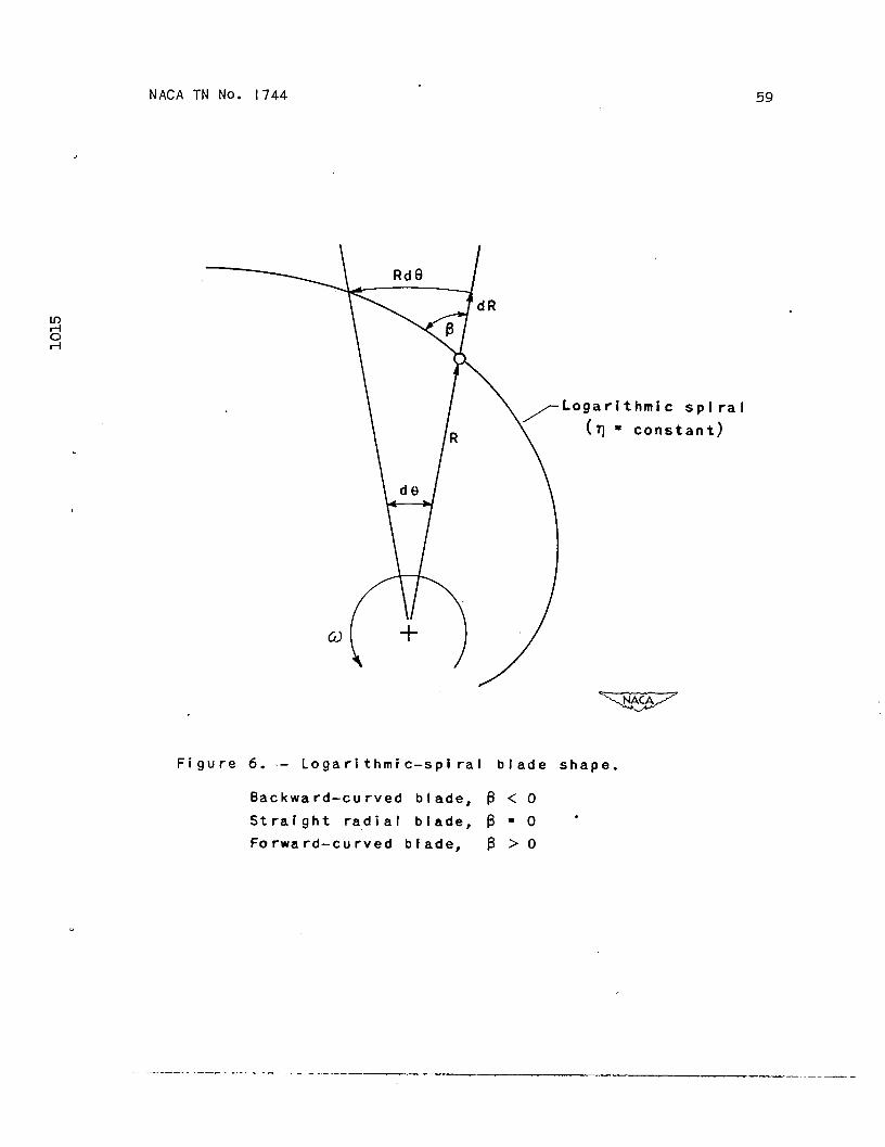
where p is the bladeourvatureanglebetweenconio-radiusntio Rand tangentto bladesurface(fig.6).
The bladeshapeti the R&plane is givenby equation(30a),which,with q constant,detemines a logarithmicspiral(fig.6).In appendixC, the angle p is shownto be constantfor a givenlogarithmicspiral. For positivevaluesof P, the bladesarecurvedforward(inthe directionof rotation);for negativevaluesof ~, the bladesare curvedbackwmil;and for P equalto zero,the bladesare stnight and zwiialalongconicradii (fig.6).
Equations(30)and (30a)relateeverypointin the R&planeto a corresponding@nt in the &q-plane.Solvingtheseequationsfor R and 8 intezmscf f-q
wR=e (31)
(31a)
In ternsof the particulartransformedcoordinatesgivenbyequations(30) and (30a),the differentialequationfor the flow ofcoqmessiblefluidthroughcentrifugalcompressorswith logarithmic-spiralbladesbecames
.
.—— —.——.- -— ——. —. .—. .,.., ,.’ ,.,

NACA m No. 1744 19
.
PasSage-hei@t ratio H. - Insteadof the arbitmmy functionfor thetion in
passage-height&tio givenby equation(2),let the varia-H be givenby
IH=~
where m is an arbitraryexponent.
U o equals CT for all values
I fluw-area?atiowith R beccxoes,from
(33)
of -R, the variationin
equations(23)and (33),
%!@ ..=— = HI=*1‘=; %%’%
the
(34)
where A is the flow-arearatio. Thisrelationbetween A andR is plottedin figure7 for severalvaluesof the exponent m.I& m equalto zero,the passa~ hei@t remainsconstant;form equal
Forequation
to -1, the passagearea remainsconstant.
logpritbmic-spiralbkdes, equation(31)is ccmibined&tih(33)and the passage-heightratio H becomes
— — .—-— ——— . ... .—— ..

20
m(E-~tanj3)
MAC.ATN No. 1744 .
. (33a)
()-*qloge: - ‘2 (!fpEmNq) (35)q ~aec$ .
Stmight -l blades.- For straightbladesalong oonioradii,the bladeamgle ~ is zero (fig.6) and equation(35)reauoesto I
(m+Z)g
%:9 ~q “$ff+$qq -“g (k%),
()-Vq lo@& -:$g (36)
n
BOcmrpressibleflov.- For ~ssfble f~, P/P. iseqml to 1.0 and equation(36)beomes
(37) ‘
where ~ is nowfictiouss~eedofC& *, t, q,
a fictioustip Mach numberbasedupon a constantsound,whichalsoappearsin the defmtionsand q.
Constantbladeheight.- For constantblAe height,the expo-nent m is zero (equation(33))and equation(37)reducesto
——— . . . .. .. .—._.— ——.. -.--—— -., .— ——.,. “.-.-

NACAm No. 1744 21
“(38)
Detailedsolutionsto this equation(inslightlyalteredform)havebeen obtainedby a numberaf investigators.(Forexample,refer-enoe 1.)
ry & equations. - Special fores& the basicMff’emntialequation(14) for steadyflow throu@ oonioalcentrifugalcompres-sorshavebeen developedfor variousdesignsand omentim oondltions.The equatims are listedin the following-table:- -
Equation Blade shape Passageheight Flow(32) Logarithmic H = f(R) Com@easible
spinal(35) Logarithmic H=~ Compressible
(36)Spilal
straight H== Compressible
(37) Stmight H=~ Inmnpressible(38) Stml.ght H = c~~t =~ssible
These deferential equations express the streamfunctionas a function of the trami?onnetlcoordinates ~andn.The
*eaua-
tions are ohmgea to fhite-differencefom ~ solved“byre-”tianmethods. Thisform is obtainedwith the aid of equations(17)andhas been obtainedfor equation(14),the finite-differencefozm ofwhich is givenby equation(18). The densityzatio p~pfiis deter-m-a frm figure4 or fzmm equation(lI.)with the ai~ o; equa-tion (19)in whichthe peter qi is obtainedfmm equationsand (47)or from equation(52b)in appendixC and in whiohthevariable H is a givenfunotlonof R (whiohis ~latea to ~VI●
NUMERICALPROCFIYURE
(lo)
A detailedoutlineof the numefioalproceduresfor therelaxat-ion solutionof impressible-fluwpnblems is givenh raferenoe8.The emphasisis placedhereinon thosefeaturesof the solutionthatare peouliarto the flow in centrifugalcompressors.
.
—-—-- —--——--—— -- - —— -— —--- .—. .— —— .—,.—

22 R4C.Aq No. 1744
The solutionof eaohdM’ferential_equationdevelopedfor thestreamfunction ~ (equations(14),(32),(35),(36),(37),and(38)) requiresspecialtreatmentdepending~n the compressordesignCha=ctetisticsand the flow conditionsthatthe equationrepresents.However,the numericalprocedureis in nwny res~ctssimilarfor all equations.The remainderof this sectionwillthereforebe concernedwith the numericalsolutionof equation(36),which is the equationused in the numericalexampleof this reTort(stmight thinbladesalongconiczad.ii).
l?mameters.- An Wpection of the differentialequationforthe streamfunctim $ (equation(36)),togetherwith the auxiliaryequations(7), (9a),(11),W (25),indicateseightpeters,which,togetherwith the bladeangle ~ (equalto zero in equa-tion (36)), specifythe designchanctaistics aud ope=tlng condi-tions of the ‘&mpr&sor.
-Des* paramet em:
(1)
(2]
(3)
(4)
(5)
(6)
%ssage-heightewnent m, whichrelates=tio H to conic-mdiusratio R
H=~
In themore geneml case, H canbe givenfunctionof R. .
Coneangle a, which is constant(fig.1)
~ssage-height
(33)“
as an arbitrary
Blademwat@e a@e P, whichfor a logarithmic-spiralbkde remainsccnstit and for straightblades (alongconicradii)is equalto zero
bcluded angle-& impellerpassageon conicsurface 0,whichis measuredfrom drivingface of Om- bladeto t=il~ingface of nextblade
M1.etconic-radiusratio RI} which iS ratioof blade-inletconicradiusto blade-tipcode mdius
Ikitialwhirlof fluidaheadof impeller,which is des-ignatedby ratio ATwfio and which is detemined by designconfigumticnof cmpressor aheadof impe~er and by flowrate (operatingparameter)throughooqwessor
●
——— .- -- ..— --—,.‘,.,. .,’---

=2
NACA TN No. 1744
O~emting parameters:
.
(7)Tip Machnwnber ~, which is defined
&T stie~
%,= .0
as
(7)
(8)Flow coefficient Q, which is defined as
(26)
I& a @ven compressm,this coefficientis easilyshowntobe proporticmalto standmd equivalent-flow-rateparameter
W+/5 (reference9)
where
13 ~tio of inletstagnationtmmpenture to standardsea-leveltempemture
?3 ntio of inletstagnationpressureto standafisea-levelpressure
(9)Ratioof specificheats 7, whichdeterminesvariationin densitymtio p/p. as givenby equation(11)
BoundaryConaitions.- The boundaryvaluesof the streamfunction are determinedby the pammeters previouslyoutliaed“andby.the Kutta conditionfor tangencyof flow at the blade tip.The variousboundaryvaluesof $ are shownon the relamtion gridin figure8. The namer ti whichtheseboundaryvaluesare obtainedis summarizedas follows:
(1)The valueof the streamfunctionalongthe driv~(:ge of‘ the blade $d (fig.8) is arbitrarilyset equalto zero.p. 14.)
(2)The valueof the streamfunctionalongthe trailingfaceof the blade ~t (fig.8) is constantand is givenby
.
—— ——.. .—— . ..— . .——. —.

24
(3)meaheadcd’the
.
valuesof the streamimpeller-bladeinlet
NACA TN I?O.174A
funotionalongthe boundariesdepend(gmongotherthings)upon
the inletdesignPamneters RI ana A%/To. For the particularease (usedin the numerfoalexmple) of straightblades (p = O)extendedto the origin,at whicha pointsouroeIs assumed(p. 27),the valuesof RI m ATw/ko are zezmand the ldt bound of there~tion grid (fig.8) is looatedat sameradiusratio R withinthe tipellerpassage. The valueof the streamfunctionalongtheleftbound ~t (fig.8) is omputed for this prtioular easef-equation(41). This equationhas beenfoundto be quiteaccuratefor valuesof R = f(~) lessthan 0.65. (Seep. 32.)
(4)The values& the streamfunctionalongthe upperbouudat the diffuser$ e (fig.8) are est-ted by equation(54)developedin appendixD. Theseestmted valuescd?V e are cor-rected.by the relaxationmethodsto be subsequentlydiscussed.
The valueaf the streamfunctionat the upperright oornerofthe gria ~r (fig.8) is firstaetermind by the estimateavalues& *e. Howemr, to satisfythe Kutta condition,the valueof *r ‘must be aP suoha mgnitude thatthe flow leavestangentto thebladesurfaceat the b~ae tip. ~ the resultingrelaxationsolu-tionfor the streamlineconflgumtionh the compressor&oesnotsatisfythe Kutta oonditicm,a new value & Vr is selected,theestimateavaluesof *e aa~ustedacoomlingly,and the soluticmrepeateaas nwy timesas is necessary.
(5)The valuesof the stre3mfunctionalongof the diffuser$f (fig.8) are,fram spet~4+ lessthan Ve.
(6)The valuesof the streamfunotionalong
the lowerboundOonsiaerations,
(39)
the rightboundc&the &&ation griaare detemined by ~r and by the a&zmption’that,alongthisbound, A$/Aq is a constant.I?orthe numeric-alexqmple,thisassumptionhas beenfoundto be accurateenoughforvalussof R = f(~) somewhatgreaterthan 1.20.
ma kyout. - Having&eterminedthe values& * at eaohpointon the griaboundary,the valuesof ~ at eachof theinteriorpotitsis estimatedand reoordeaupon the gria sheet(fig.8),whioh shouhlbe sufficientlylargeto accommodatethe0810ulationsreqnireaby the re~tion pZWC-. After estlmati.ng ‘
.
.— ~— .~—. ...
L- ,,.,
NM2A TN No. 1744
the interiorvaluesof ~, the problemresolvesitselfintotwoparts: (1)calcul.ationd?theresldual Q resultingfrom theestimatedvaluesof $, and (2)relaxation(e13nination)of theresidualby suitableadjustmentsin the estimatedvaluesd w.
Residuals.- In orderto detezminethe residualat eachpointof the grid system,the partialdifferentialequation(forexample,equation(36))is e~essed in f~te-difference formby methodsoutlinedin the analYsis. All termsof the equationare placedequalto the residual Q, as has beendone in equation(1.8).Thetermsinvolvingthe densityratio p/p. are detemind fromfig-ure 4 or equation(11)with the aid of equation(19). In ordertodetezminethe valuecf the densityratioat the boundarypointshthe im~eller,it is necessaryto extmpolatethe values& thestreamfunction $ by gmphical or numericalmethodsto obtainthe velocitiesat the boundary. In the diffuser,however,thisextrapolationis,not required because the values aP $ repeatthemselvesin a continuousmannerfrom paseageto passage. E theestimatedvaluesof $ at all grid pointsare correct,the valueof Q is zeroat all points. E, however,the estimatedvalues*of $ are incorrect,the valuesof Q are finiteand may bepositiveor negative.
Relaxation.- With the residualsat eachof the grid pointscomputed,it remainsto relax (thatIs, reduce)theseresidualsbysuitablechangesin the valuesof ~. In orderto determinethemgnitude of the requireschangesin $, all temns& the fi.nite-differenceequation(equation(18),for example) are assumedtoremainconstantexceptthe term 4~ . A chmge in the valueof Vwill thereforecausea four-foldchange& opysite signin thevalueof Q. This changein the valueaf $ will also causeanequalchangein the values.of Q at eachcd the adjacentgridpoints(fig.3). Thesechaagesin V and Q are recordedon thegrid sheetas the wcrk progresses.By continuallyrelax3ngthelargerresidualsany desiredamount,the valuesd all residualsgraduallyapproachzero. When thisconditionis reached,the sresidualsare recomputedusingthe finite-differenceequationandtaldngintoaccountthe new valuesof the densitymtio. Whenthe new valuesof Q have been computed,the relaxationprocedureis repeated.as &ten as necessaryto achievethe desiredaccumcy.
Accuracy.- 190quantitativeevaluationof the accuracyofrelaxationsolutionsis available(reference10, p. 176). However,becausethe computed,velocities(andpressures)dependupon dM-ferencesin the valuesof the streamfunction V at adjacentgrid
.. —. ——- ... .. . ..-— ..-— —.-. ... . .... . ..—. ,.-. _ —— - —-—.-———— —-. -..—— —.-——

26 NACA m No. 174A
points,that is, the smalldifferenceaf largenumbers, it isimportant to Imow the values of $ with tificient acc~cytoassure the desired accuracy for the pressure and velocity calcula-tions . bthis report, the values of $ were computed to thenearest0.0001compardwlth themaximumvalueof ~ at the *il-ingface of the bladeof 0.I-570.The resultingvaluesof pressureand velocityare estimatedto be accumte within1 or 2 percent.
Final solution.- The streamlineconfigurationcanbe deter- .minedfmu the f=l valuesof $ at -ch ~ the -d Pofitse(Streamlinesare lines& constant ~.) E the streamlineleavingthe tip @ the impelleris tengentto the bladeat the tip, theestimatedvalueof $r (p. 24) is correct;otherwisea new valueof ~r must be selectedand the entiresolutionrepeated.
Afterthe correctdistributionof ~ on the grid is obtained,the preBsuredistributioncanbe determinedfrom the densitydis-tributim and the Mach numberdistributioncanbe detemdned from
7e uation(19),the densityratio,and the speedof soundzatioc co, which is relatedto the densityratioby
●
c—= ()-&Zco Po
mom the preceding idomathn, suchquantitiesas the @?ellerslip (appendixE), the boundary-kyergrowth,and the blade loadingcan be est-ted.
NUMERICALIEMMm?l
Designand operatingpammeters. - A nmerical examplehas beencomputedfor the followingdesignand operatingprameters:
Desi&?nparameters:(1)(2)(3)(4)
(5)(6)
Go&&tflow=ea, m. . . . . . . . . . ● s . ● “ ● Q ● ● -1Coneangle, u, degrees. . . . . . . . . . . . . . . . . MOStzaightbladesalongconic mdii, P . . . . . . . . . . . 0~chded~s=ge~le) a=~T . . . . . ● ● . ● ● ● ● 2fi/20(20thinblades)
Inletconic-radiusratio, RI . . . . . . . . . . . . . . . 0
Initialwhirlof fluidapproachingtipellerinlet, ATw/To. . . . . . . . . . . . . . . . . . . . . . 0
.— .7- ~.,—.~ ~ —.— —.. -,,, .. ,’

NACATN No. 1744 27
Operatingparameters:(7)Tip14achnumber, ~...... . . . . . . . . . . ...1.5(8)Flowcoefficient, cp . . . . . . . . ..o . . . . ..e .005(9)Ratioofsyecificheats, 7 . . . . ... . . . . . . ...1.4t
b orderto insuresteady-flowconditions,a vanelessdiffuserhas been selectedalthougha varieddiffuserlocatedfar enoughdown-streamof the impellerwouldalsobe satisfactory.(Seep. 5) Adiagmm of the impellerand the vanelessdiffuseris shownin fig-ure 9. The passage-heightratio H variesin sucha mannerthatthe radial-flowarea remainsconstant. The straighthpeller bladesare extendedradiallyinwardto the centerwherea ~int sourcehasbeen assumed. A pointsourceat the centerof the impelleror acircularlinesourceat some conic-zadiusratio R must be assumedin the two-dimensionalanalysisin orderto supplythe tiyellerwiththe necessaryflow rate. In this e-le, the stmight bladeshavebeen extendedto the center (R1=O) to obtainsmooth(shockless)entryto the straightblades (withoutprovidinginletwhirl). bpractice,smoothentryto straightbladeswithoutinletwhirl isobtainedby curved.inducervanesinvolvingflow that is not alongaconicsurface.
The resultsof the numericalexampleare presentedin fig-Ures 10 to 15. Thesefiguresare discussed.
Streamkbles● - The streamlineconfigurationrelativeto therotatingimpelleris shownin figure10. The grid lines on the fig-ure indicatethe grid spacingused to obtatithe finalrelaxationsolution.The streamlinesare designate in sucha mannerthatthevalueof the streamlineindicatesthe percentageof flow throughthe passagethat liesbetweenthe streamlineand the drivingfaceof the bide (rightsiseof passage). For example,20 ~ercentofthe flow throughthe passageliesbetweenthe streamline0.2 and.the drivingface. It is interestingto note that 20 percentd theflow occupiesmore than 50 percentaf the flow areaat a mdiusratioof 0.86● The spacingof the streamlinesis indicativeof thevelocitiesin the compressor;the mailer the spacing,the higherthe velocity. The highestvelocitiesthereforeoccuralongthetzail’lngface of the blade,the lowestvelocitiesnear the drivingface. “
*
As a resultof the irrotationalityof the absolute.fluidmotionin the vanelessdiffuser,the absolutetangentialvelocityof thefluicldecreasesas the radiusratio R increases.The tangentialvelocityof the fluidrelativeto the rotating R,8 coordinate

28 NACATN No. 1744
systemthertiore,decreasesmpidly (takeson largenegativevalues)in the diffuserand the relativestreamlinesin the diffuseraresteeplyslopedin the ddrectionoppositeto the impellerrotation,as shownin figure10.
Eddyfomation. - For the designand opez%ztdngconditionsofthis e~le, a wheel-typeeddyformson the drivingface of theblade (fig.10). ‘Ibiseddy is attachedto the bladeand“rotateswithan angularvelouityequaland oppcsiteto the rotationalvelocityofthe impeller 0. (Themotionis not a simplerotationbut a cm-b=tion of rotationand deformationreqtied to satisfyboundaryconilitims.) such eddiesfom at low flow nxtesand resultfromthe comlitionof irrotationalityrelativeto an absolutesystemof coordinates.
Aneqanded view of the eddyis shown in figurell. The flowmxke within the eddy amounts to lessthan 2 percent@. the flowratethroughthe impeller(asindicatedby the designationof thestrem13nes). This lowfluw =te indicateslow velocitieswithinthe eddy.
It appearsthat,in an actualcompressorunderthe influenceof viscousshearingforces,the sizeand the positionof the eddymightbe unsteady. Undertheseconditions,the pressureforcesare not in equilibriumand theflow is unstable. It may thereforebe desirableto ellminatethe e~ by pnper changesin the design ‘-andthe operatingconditionsof the compressor.
The eddy cm be el~ted by the followingmethods: Whenthe flow mte throughthe zmtatingimpelleris zezm,the eddyoccupiesthe entireflow passage(reference1, p. 1000). The eddyis therefore reduced ad finallyeMminated by increasingthe fluwratethroughthe impeller. The increaseh the flow rate,however,is limitedby chokein the c-essor. ~ this event,it may bedes~ble to replacethe eddyby a solidplug of lightmaterialattachedto the impellerbladeand disk.
Kutta condition.- Genemlly, severalattmpts are,reqtireato satisfythe Kuttacodlition.The secondattemptis showninfigtme12(a). Thisfigureis an exed ~ew d-the regionin thevicinityofthe bladetip. Streamltie1.0 doesnot leavetangentto the bladetip. In this case,to satisfythe Kutta conditionoftangency,it is necessaryto reduoethe circulationaroundthe com-pressorby increasingthe assumedvalueof ~r. (Seefig. 8ad p. 24.)
,
.-
.— . .—---- —.——.—. . ., .--’‘.’” .,.,. .-r

NACA TN No. 1744 29,
The thirdattemptto satisfythe Kutta conditionis showninfQure L?(b). Streamline1.0 is verynearlytangentto the bladetip. This sOlutiOnwas 00~iae~a satisfactory.
Slip.- The computedvaluesof the slip factor(appendixE)as determinedfrom the streamlineconfi~tion were 0.91for thesecondattemptto satisfythe Kutta conditionand 0.90for the third(f&l) attempt.
ConstantMach nwnberlines.- Linesof constantMch numberrelativeto the tipellerare shownin figure13. A maximum100alMachnumberin the-impellerof 0.64occu& on the trailihgface ofthe bladeat a mdius ratioof 0.68.
The maximumrelativs Mach number at the impeller tlp is lessthan 0.30. The lat relativeMach numbersat the tip resultfmmthe high tip speedof the impeller,which inoreasesthe densityandtheraforereducesthe velocity.
The somewhatirregulOrvelocityprofileat the impellertipbecomesqtiteunifomnwithin6 to 8 percentof the hpeller ndlusbeyondthe tip. This ~pid adjustmentof the flow indicatesthat,providedthe absoluteleavingvelocityis subsonic,varieddif-fuserscanbe,locatedquitecloseto the impellertip withoutappreciablelossesresultingfrompoor (unsteady)velocitydistri-button relativeto the stationarydiffuservanes. However,in thepresenceof botiry layerand separation,the velocityprofilewouldbe considemblymore inegdar thanobtainedin this solution. Therelativelyclosespac~ of theMach numberlinesalongthe trailiugface of the liklenear the tip indicatesnpidly de~le~ted flow,which is conduciveto boundary-layersepa=tion.
Constant-pressure-mtiolines● - Linesof constantpressuremtio are shownin figure14. Withinthe impeller,the pressureson the drivingface of the bladeare higherthan the pressuresonthe tmiling face. Thisdifferenceh pressureacrossthe bkdeaccountsfor the impellertorque.
An eqanded viewof the pressureratiosin the ticinityat thebladetip is shownin figure15. As a resultof the Kutta Condi-tion,the pressures(andthe velocities)are equalon both sidesofthe bladetip. This unloadingat the bbde tip deoreasestheimpellerwork and thereforedecreasesthe hpeller slip factor.
.
0
——.——. .. —..—--—..—_ ——. - . -— . .-. —.— — —. — .— —. ————

. .
30 NACA ~ No. 1744
SmmmcED ANALYSIS
The relzmtim solution pz%!sented in this rqymt Is lengthy.It wouldthereforebe advan~eous to have a quicker,although lessaccurate,meansof estimatingthe flow conditionswithinthe impeller.In this section, a simplified analysis developed in appendixF fortil-disc~e and mixed-flowimpellerswith sttight blades (alongcaui.czadii)is discussed.
Velocitydistribution.- The simplifiedanalysisis basedonthe assumptionthatthe tangentialccmpmnt of the velocityrela-tiveto the impelleris zeroat all mdii withinthe impeller. Thissimpklf’tedamlysis includesbladesof var@ng thiclmessprovidedthe variattonis not sufficimtlygreatto resultti appreciablevaluesof the tangentialccmpment af velocityto the impeller u.The imotati-lit y equation(5)reducesto “
+sin2=L*2 R M
which,when titegmted betweenlimits,and so forth,becaes
v “—=—., ‘o co
where ~a is the velocityalong(e=0), whichis detemined fromfollowing~m.
+
+-e (40)
the dri~ face of the bladecontinuityConsi-tions in the
Streamline distribution. - Fmm continuity considerations andfmm the velocity distribution given by equation(40),the follow-ing expressionis obtainedfor the streamlinedistribution(appenaix F):
{
- 1+
—-—. — –— v--— -. —— --- —--—-.:7. ---.—. -–— ---- -. -- ---- -r- — - - ..-,., . .:. -

NACA TN No. 1744 33.
wherethe constantterm ATwfio is evaluatedby equation(9a). 5evelocityratio vd/co is obtainedby equation(41)from the condi-tion that
when
e =U
When the velocitymtio vd/co is determined,equation(41)expressesthe streamlinedistributionas a functionof the coordi-nates R,6 ad the tip”~ch nwnber l%.
Discussim. - The velocitymtio alongthe drivingface ti theblade~s been computedfrom equation(41)for the same con-ditionsused in the relaxationsolutionof thisreport. The resultsof this computationare shownin figure16 and are comparedwith theresults obtainedfrom the relaxationsolution. The agreementbetweenthe relaxationsolutlonand the approximatesolutionissatisfactoryup to a radiuszatioof about0.85. Formiius mtiosgreaterthan0.85,the assmption thatthe u componentof thevelocity,and its derivati~,may be neglectedis no longervalidbecauseappreciablechangesin the u componentnear the bladetipar6 required,fmm momentumconsidemtlfi, to unloadthe blade.
EL can-paringthe flow Chanmteristlcsacrossthe passageobtainedfrm the relaxationsolution- the approximatesolution,the ndluE ratios0.675and 0.855shownin figure16 will be used.
The eddyfomnedon the drivingface of the blade (fig.10)has “two stagnationpointsontheblad.e. The velocityalongthe drivingface of the blade is zeroat radiusratioscorrespondingto thesestagnationpoints(fig.X3). The smallerZW31usmtio canbe pre-dietedby the approximatesolutionfrom theplot of vd/co in fig-ure 16. The estinatedvaluecd?the m@iua ntio is 0.703ccmparedwitha valued 0.713obtainsdby the relaxationsolution. Itthereforeappearsthat the presenceof the eddy canbe p~ctedwith fair accuracyprotidedthe eddy occursat a mlius ratioforwhichthe Mmplifiedanal.ysisis valid,that is,fora radiusratioat whichthe u componentti the velocitymay be neglected.
The velocitytistributionacnssthe passagehas been computedfrom equation(40)with the computedvalws of vd/co given~figurei6. This vel.ocitydistributionis plottedIn figure17 for
.-—. . .. . . . ——. .-. .—..= . ... .. .—.. . .=. —c. ..—.._____ .—— _..-----._.._.— —-—.-—-—-—

. . . . .. . . . .-. .—---— — -
0
32 MACA TN No. 174A
naius =tios of 0.675and 0.855and is comparedwith the co?zre-spondingvelocitydistributionobtainedby the relaxationsolution.The velocitydistributionala radius=tio of 0.675is nearlythessmefor both solutions.At a radiuszatioof 0.855,the agreementis stillsatisfactoryalthoughthe slopesd’ the two curveshavebegunto de~te. This deflationbetweenthe solutionsresultsfrom the bladeunloading.
The streamlineUstributionacrossthe ~ssage has been com-putedfrom equation(41)with the computed.valuesof ~&/co given
in figure16. This streamlinedistributionis plottedin figure18for radius=tios of 0.675and,O.855and is comparedwith the corre-~ st~~ distributionobtainedby the relaxationsolution.The fact thatthe streaml~ Mstributionat a *US mtio of 0.675is nearlythe samefor both solutionsindicatesthqtthe boundaryvaluesof $ at the leftboti ~z (fig.8) =be computedbythe a~rorhnatemethodfor -us ntios at leastas high as approx-inatelyO.65. At a -US =tio of 0.855,the streamlineiMstribu-tion,althou@ satisfactoryina qualitativemanner,has beguntodeviateappreciablyfrcmothe more rigorousrelaxationsolution.
X’ressure=tio. - The ~essure ratio in the impellerpassageis givenby (appendix?)
where Va/Co is determined fmm continuityconsidentionsasdescribedon-e 31.
The pressure ratioacrossthe passagehas been computedfromequation(42) with the appnximate valuesof vdlco givenin fig-ure 16. This pressuredistributionis plottedin figure19 forradiusratios.of 0.675and 0.855and iS ccmprd with the carre-SPO_ pressuredistributionobtainedby the relaxationsolution.The pressuredistributionat a mtius mtio of 0.675iS ~arly thesamefor both solutionsand at a radiusratioof 0.855the agree-ment is satisfactory. .
Blade loading - The bladeloadingat any givenconic-mdiusratiois givenby ~he differencein pressurebetweenthe drivingface and the tmiling face of thebkde. From appe- F, thisdifference is given by
I
o
—.—— .-— —- —-- -.. ——-- —-. —..-——---—-—--,-—- —- ——— -. -—. v—
./ .... . . . . .,’.

NACA TN No. 174A 33
The blade loadinghas been computedfrom equation(43)and isplottedin figure20 togetherwith the correspondingcurveobtainedfrom the relaxationsolution. The two curvesare in good agreementfor mdih ratioslessthan 0.825. At higherradiusratios,how-ever,the bladeunl~ilsfor the relaxationsolutionwhereastheblade loadtngcontinuesto increasefor the appmmimate solution.W orderto correctequation(43)for the bladeunloading,the fol-lowing relation is assumed:
wherethe exponent x is detemined byconsiderationsgivenb appendixF
(1 - IF) (44)/
the slipfactor w from
(45)
In the numericalemample$the valueof p obtainedfrom therelaxationsolutionis 0.90,for which,from equation(45),thevalueof x is 18.0. Equation(44)for the blade loadingthere-fore becomes
(44a)
CONCLUSIONSAND SUMMRY~ RESULTS
A genemalmethodof -lysis has been developedfor two-dimensional,steady,compressibleflow in centr~ugal compressorswith arbitmry blade shapes,arbitmry variationsin the passageheight,and with fixed coneangles (rightcircularcons generatedby the centerllneof the flow ~ssage). lRromthisanalysisthefollowingconclusionscanbe drawn:
-.. .— —.—-- .—— ...___ __ _ ____ “r..__ ...—— . — —.—. ~ ~. .— . —

.— - . .._. ___ ——L —.. — ..—
34I
The solutionother cone angles
NAM m No. 174
obtainaifor a givenconearglealso appliesto(thatis, otherM.xed-fhw compressors)with a
fewer or a greaternumberof passagesbut with the _ includedpassageangle,and so forth. Mixed-flowcompresseswith thesamenuuiberof flowpassagesas radial-dischargec-essors adtherefae with smiler includedpassageangleshave luwerpeakbladeloadlngsand lowermdmum relative velocities than thecorrespmding radial-discharge compressors.
!Thegeneral analysis also applies to inward-flowturbines.me solutionobtainedfor a centrifu@l compressa with mooti(shockless)edtryis also tie solution(withthe flow directionandrotationreversed)for an inward-flowtumibinewith the samedesignchsractetistics(thatis, the samerotor)and with smooth(shoclil_ess) ,entry.
Wam a Inm9rical enmple. of a radial-dischargecmpressor wltih20 strai@t bladeslyingon conicradii,cons-t flowarea,anMet radiusmtio of zero,a tip &oh nunhr d 1.5,and a flowcoefficientof 0.5, the followingresultswere obtained:
1. A wheel-we eddy formed on tie driving face of the impellm.
2. ~ velocitiesand pressuresat the impellertip werereasonablyuniformand ~ nonuniformi~in the flow leavingtheimpellerrapidlyadjusteditself.
3. me ~ locall&ch numberrelativeto the impellerwas0.64and occurredalongthe ~ face of thebladeat 68 per-centof the tip -us.
40 !Jhec-omputi sMp factorwas 0.90.
.—.,. —. . . . . . . . . . .. ...—_ .—. __-..., -.’, :,—,L’

\
N4CA m No. “1744 35
IIIaddition, a simplified analysis for strai@t blades I@ngon conic radfi is Psented which can be used to determine the,streamlines, ~ssure distribution, and velocity profiles withinthe impeller Oxoept near the tip (and inlet).
Lewis might l?ropulliion mhrato~,I!Wtiad. Advisory Committee fw Aeronautics,
Cleveland, Ohio, August18, 1948.
— .. ——--——. _.— ——.—.

NACATN Ivo.174436
API?ENDIXA
SYMB’OIS
The followingsymbolsare used in the analysis:”
flow-area ratio, I#q
flow area, normal to conic surface
A
a
B numberof blades(orpassages)
~id spao~ (fig. 3)b
local sped of sounda
specificheatat constantpressureCP
F any twice-differentiablefunctionof two variables
accelerationdue to ~vity
passage-heightratio,h/~
h pamage height, normil to coniu surface
J mechanical equivalentof heat
K Condant.
@rT sin ~impeller tip Bkch nmnber,
co%
passage-height exponentm
constantN
static pressureP
Q residual
velccityrelativeto fmpeller,m
conic-radius ratfo, r/qb
conic radiua (distance along conic element from apex of cone)
/
r
T absolutetemperature
.. . —. ,,-- ,—~~. ——- --- -- –—– —-–—-.,. ,. ,. ,.

. NAM TN No. 1744 37{
u tangential component of velocity relative to impeller (positiveIn dtieotion of rotation)
v radial (along co’ticelement) component of velocity
w compressor flow rate (total)
w flowrate betweenstreamlines .
x exponent for blade-loading correction
z complexvariable
a ooneangle (fig.1)
P bladecurvaturean@e (fig.6)
r “absolute c&culation
7 ratioof specifioheats.
A- finiteinorement
5 ratio of Met stagnation pressure to standard sea-levelpressure
v Imansfo+ coordinate(incompressiblestream function)
e angle,radians(fig. 2)
e ratioof Met stagnationtemperatureto standardsea-leveltemperature
P’ slip faotor
E *formea coordinate (incompressible velocity potential)
P weight density of fluid.
0 included pass@e. angle, (et - ed)
T impellertorque
v wflow coefficient, —
PO%PO
w ccqressible stream function
(0 impellerangularvelocity
● ✍
______ _ —-— ----- —-— —————. ..—.—.

-—. -
38
subscripts: ‘
av
d
e
f
I
i
z“
o
NACA m Nb. 1744
awzpge
drivingfaceof blade (fig.8)
upper bound of
lower bound of
impeller inlet
incompressible
diffuser (fig.8)
diffuser(fig.8)
flow
left botmd (fig. 8)
absoluteinlet stagnation condition
right bouod (fig.8)
simplifiedsolution
impellertiy
trailingfaceof blade (fig.8)
whirlaheadof impeller
partialderivativeswith respectto R, 8,~ , and.q, respectively
seconLpartiala with~,q, andganaq,
grid yointe adjacent
respect to R, e, R and e,respectively
to point in question (f]g. 3)
.
—. —._ .__. ,- . -~ ,’ ~.--Y:. .——.. _

$
.
NAC.A TN No. 1744
~RMNIION
FOR FLOW
FROM
39
APE!ENDIXB
The confm transformation (exoept for singularpoints)fkanthe R& to the ~q-pla.ne,where- ~ and q are the velocity potentisland stresm function, respectively, for incompressible flow throughthe stationary impeller ((0= O) with constant passage height (H= 1),is givenby the -ic function
.
f(z)’= f(Reie)= ~ (R,e)+ iq (R,e) (13)
where ~ and q are functions of R and 8. l!herefaej
1
The velocity potentfal ~ and the streem function q are relatedby the Cauohy-Riemanndifferential equations
(47)
After equations (46)and (47)sre ccmb&d, the ~tistthreetermsof the rightsideof equation(6)become
(
\
-——. — — .—. _,..

But, because
NACA ~ NO. 1744
f(z) is analytio,
allafromequation(47),
$+%t2”’i+ 2=%2where q~ is
w Impel.la
.
the velocity for ino~essible flqw”throughthe *tion-(W= O) with uonstantbladehel.ght(H = 1). Therefore,
(48)
The fourthterm of the right”sideof equ@lon (6)beaxnes
where H is now a funotionof ~ ami q Ins~ of R alOm.
The last two terms of equation (6) in likemannerbemne
.
.— . — ..-—. —-- .——. . . .. . . _ ...— — .— ——,-. T- .,- .,..

.
I\
i
E4
(14)
\

42 NACA TN No. 1744
APPlmmx c
D~ IKUJATIOI?FOR FLOW TmouG3ammFmAL
coMeRFssomWITH ImAmTmIc-mm BLADEJ
Considerthe analyticf’urmtion,
f(z) = (Iv+ iK) loge z
= (H + K) loge (Reie) “
= (E + m) (loge R + ie) /
= (Nloge R -Kc) + i(Klo~R +Ne) (28)
where N and K are constantsto be determinedby the boundarycon-ditions. Fimmequations(13)and (28),
g = If(logeR -~e) (29)
oge R+e)q= E(:l ‘ (29a)
The blade shape in the Re-plane is givenby equation(29a),which,with q constant,detemlnes a logarithmicspiral(fig.6).
h onier to determineis differentiated with q
or
But, frcmfigure6
the constants H and K, eqwtion (29a)constant ,
o=KdR~T+-de
K Rae.s-—l!l dR
—.-..., .:. -,-——-—- ——,-, .. .. . . . ,,

NWA TN No. 1744 43
p ~ *-1 Rae%x
where j3 is the angle between blade surfaoe and mnio-mdius ratio Ron Re-plane (d on 04mio
k-=-N
and equation (29a)bemmes
suzfaoe). There&me,
* p . Uonstant ,
q= H(8-taI~l~R)
In -r to determinethe constant N, let
n=vt(
when
O=(7T
R = 1.0
(fYomwhiohthe zeropointfor e is at the tip of the driving face
of the blade). Therefore,. from equation (51),
$%H=—
● ‘T
whioh,fkcm equation(25),is equalto the flow ooeffioient@ andthe finalexpressionsfor ~ and ~ bemue
~=q(lOgeR+e*P) (30)
n = 9(~ - tan ~ logeR) (30a)
Theseequationsrelatepointsin the Re-planeto correspondingpointsin the ~q-plane,Solvingequations(30)ad (30a)for R and O intermsof ~ and q gives
(51)
.
—.. —— — —

44 .
bMQ ,~=epsec2p
(31)
I&m equations(lS),(30a),and (31),
Id!wkL-tq=cptanf3ePBe~2B (52)
MifwkL’vi . qe
cpt3e02p.
SO that
(52a)
(lo)
2w!%fkL=Peec $ e cp seu2 p (52b)
Fran equations(14)- (52)to (52b),the ~.ferentlalequationforthe flov d compressiblefluidthmngh centrifugalcompressorswithlogarithmic-s@ralb~es becomes,in terns& the transformedcoonlinates ~tiq,
Coa sin[( 00s p (loge H)n (32)
,—._. ___,,. :— .- ,,.,. ’..,

NAC.ATN No. 1744 45
10l-l0l-l
APPENDIXD
PROCEUUREFOR FSCIMATINGBO~ VALUISOF STREAM
FUNCTION * m VAREIJ3SD-ERS
Eathatd boundary values of the stream funotion V in vanelessd&users oan be obtained by assming, as a first approximation,that the flow in vaneless diffusers is one dimensional, that is, afunction of R only. I&cm the conservation of the moment of momentum,
where W, the slip faotm, Is defined In appendix E. Therefore,601v@ for u, diVi~ by” Oo, - expressing in terms of R
t
In general, the slip flsotm p depends upon
(53)
the blade shape anduponthe Operating Ix3@itionstions (4a)and (53)gives
WR=
of the mnpressor. cCfmbini&eqla-
(54)
TMs equation gives the variation in the stream funotlon with the
radius ratio R for a constantvalueof e. Beoausethe densityratiois also a fuuotionof R, bquation (54) is solved by nunerioalpoint-by-point methods. In omler to obtain this solution, it isfbat neoessary to know the density variation with R.
The density ratio is given by
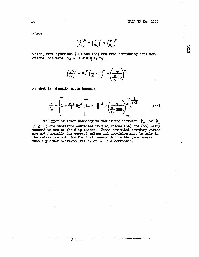
~= 1+%~%)’-($y -$ (n,
D
— ——-—— ---—— —-.—- . ..— ---- —..— ___ .-— — .-— — .—,,
i46
where
which,
NACA m No. 1744
(s=(its+(Htian equations (26)and (53)and from oontintity oonsider-
($)2=%2(:-.)2+(~)’o
so that the density ratio beoomes.
The upper or lower bou&.ary values of the diffuser $e or $ f
(fig.8) are therefore estimated from equations (54)ad (55)usingassumed values of the slip faotor. These estimated boundary valuesare not generally the oorreot values and provision dust be made inthe relaxationsolutionfor theiroorreotionin the samemannerthatany otherestimatedvaluesof $ are oorrected.
.
-—.. - .-.-”. -—.————. —-..,.,,., .

APPENDIXE
.
.
.
NACA ~ NO. 1744.
47
PROCEDURRFOR COMPUTINGIMPELLER~ FACIVR “
The impeller slip factor is defti as the ratio of the averageabaoltrte tangential velooity of the air as it leaves the impellertip to the tip speed of the impeller.
0
‘h
(56)
The averagevalue of the tangentialvelooityrelativeto the impellerat the iinpel.lertfp is givenby
which,fromequations(22) and (25), reduoes to
R)a.”if(tm($)’(%!) (57)
— --———. .-—-—____ ——-————————-. .— - .———- --..—. . —________ ._._ .

.
Equation (58) gives a weighted avemge value aE’ u/co. Thisweighted average value C& u/c. is also equal to the unweighteii
.
[()
‘t
avmage value of u/~, which is equal to ~ & decJT . This fact
00
can be shown from -identi~ of the conservation of angular
momentum in the diffuser, which is basea upon tlieweighted avenge
value d u/o. and from considerations d constant absolute C*
culationin th~ diffuser,which is basedupon the unweight&laaver-age value of U/C.. Combiningequations(56)and (57) results in
the following~ression for the slip factor:
The valueof the integral3.sobtaineaRromof the integmnd evaluatedat the impeller
“e - eaangleratio — (fig.21)..The value
~T
obtainedfrcmthe relaxationsolution.
the area undera ourvetip as a functionof the
of the integrandis
)
.,- , ---------- . .. . .-. .._ —- --—.—.” . . .,. ,-

NAM TN No. 1744 49
SIWUF3XD ANAUSIS FOR RADIAL-DISCHARGEAm MIXED-FLOW
AIaNGComeRADII
Velocitydistribution.- This s~lified-lysis is basedon theassumptionthatfor mntfiugal compressors with stmight blades alongoonic mdii the tangential component of the velocity relative to theimpeller is zero at all -i within the hpeller. The irrotationalityeqwtion (5) therefore reduoes to
.
whioh,when integmted with respectto (1 betweenlimits,beoomes
v=v&+ *sin ~ Re/
whioh,in t- ditidedby the speed of sound at inlet stagnationconditions beoomes
v—=00
where ,vd is detenmlned fmm
lowing ~Ph*
‘a<+-e (40)
continuity oonside~tions k the fol-
Streamlinedistribution.- Heglecti.ngthe u oompnent ofvelocity,the continuityequatianbeoomes(fig.2):
dw = P-e
The density p 1s obtainedfrm eqtition(11)with q/o. equaltov/o. and the velooityratio v/o. is obtainedfrom equation(40),so that
— . . ..-—— .-— — -,.-—.. ~ ---- .+- . —--- . ——~——— —- ——-- -

50
.
IW2Am’Iro.1744
dw—=‘o”o*T {[
HR” 1 +% (q)z
(>+,-Co
where‘theoonetanttem
)2RM@ de (59)
equation(%).AT#Co is evaluatedby~tegratlng the rightsideof equation(59)between the limits Oand e and notingfrom equation(20)that the laft sideof equa-tion (59)iS equalto av, whiohis integratedbetween O and ~,gives
Equation(41)eqresses the streamlinedistributimas a functionof the ooo~tes R,e a the tip Mach number ~. The velocity~tiO VJCo is obtainedby equation(41)from the oonditionthat
when
fromPressure ratio. - Thethe temperature ntio
pxmure ratiois direotlydeterminedby the thermod.ynemiurelation
7-1
()2=+Poo’
—— -—.——- -,- ._— .—-— .—— — —--... - . . . . . . ,.
NACA m No. 1744 51
.The temperature =tio is given by equation (9) in whioh the velooitymtio q/c. is equalto v/c. givenby equation(40)so that
9
where vd/oo is detemined f- continuityoonside~tionsas pm3-viouslydescribed. ‘
Substitutingequation(42)into equation(41)resultsin
(60)
The streamfunction W amd the pressurezatio p/p. are there-fore relatedby the simpleequation(60).
‘Bladeloadhg - The bladeloa&lngat any givm -us ratiois givenby the &ereno.e in pressurebetueenthe drivingd “trailingfaoesof the blade. From equation(60)this differenceis
whioh, from equation (25), beccnnes
The bladeloadinghae been ccnnputedfrom equation (43) and isplotteda@nst the conic-mdiusmtio R in figure20 togetherwiththe correspondingcurveobtainedfrom the re~tion solution.The two curvesare in goodagreementfor radiusratioslessthan0.825. At higherratiusratios,huwever,the bladeunloadsfor therelaxationsolution,whereasthe blade loadingoontlnuesto increasefor the appmximte solution. In orderto oorrectequation(43)for the bladeunloading,the followingrelationis assumed,
.-— — _ ___ . ..— —.. ~— . ..—

52 NACA TN No. 1744
(44)
wherethe exponent x is detemined by the slApfactorf- thefollowingconsidemtions:
The hpeller torque T is Ob*~a from the Mf’ferentlalequation
which expessedR and combined
d.?
the ddmnsionless coordinates H andwith equation (44] results in
= Bpo 27% q@& sin ~R(l-~) dR
Jhtegmtingbetween the l-hitsof R equalto O, assumingthebladesextendto the origin,and R equalto 1.0 gives
(61)
The torquecan alsobe obtaineafrom an exp?essia for theimpellerpower,which includesthe slipfactor p,
which,titerhavingbe= combineswith equations(7), (23),~and(26),the tezmmbeingrearmnged, becames
@o 7~w*2 Sfi g (P) (62)
From equations(61)and.(62), the exponent x is obtai.neaas efunctionof the slipfactor w.
%
.=* (45)
..— _ _. . .. —- —..

NACA TN No. 17# 55
The valueof p obtainedfrom the relaxationsolutionis 0.90r whioh,from equation(45),the valqeof x is 18.0. “EquR-Lon (44)for the blade loadingthereforebecomes
1.
2.
3.
4.
5.
6.
7.
8.
9.
(44a)
Stodola,A.:, Stealn and (kS Turbines. ~01. ~. McGraw-~11Book Co., ~c., 6th ed., 1927,pp. 998-1006,1255-1260.
S&ensen, E.: E’otentialFlow throughCentrifugalPumpsandTurbines. NACATM NO. 973,1941.
Betz,A., and Fl&e-Lotz, I.: Design& CentrifugalImpelierBlades. ~A~Ho. 902, 1939.
Bollay,”William: The Theoryat Flow throu@ Centrifu@ Pumps.Theodme von K&n&n AnniversaryVol.,Contributionsto Appl.Mech.and RelatedSubjects,C.I.T., May 11, 1941,pp. 273-284.
Concoraia,c., and Carter,G. K.: D-C Network-AnalyzerDeter-minationof Fluid-Flow~ttezm in a CentrifugalImpeller.Jour.A~l. Mech.,vol. 14, no. 2, June 1947,pp. Al13-Al18.
Southwell,R. T.:ClarenaonPress
Southwell,R. V.:ClarendonPress
Re=tion Methods(Otiora),1940.
Re~tion Methods(=OZ’d), 1946.
in E@neering Soience.
in Theoretical Physics.
BllmIls,Hoyard w.: The I!Wmezzbal Solution of .CompressibleFluid Flow Rroblems. NACA TN NO. 932, 1944.
NACA Subccmmltteeon Compressors:Standard2roceduresfor Ratingand TestingMultistageAxial-FlowCompressors.NICA TNNO. 11.38,1946.
IQ Enmions,HowardW.: The NumericalSolutionof PartialD~er-entlalE@u3tions. Quaz%erlyAppl.~th., ml. II, no. 3,Ott. 1944,pp. 173-195.
.. -- ———.——..—..———— ___ .—— . . . . . . ... .. -—. —.-— ._

54
.
NACA TN No. 1744
.Im@ler
3M1’fuser
.
.
/
Figure1.-Fluid~icle on rotatingcoordlmte system of impeller. Center line of flowp9sssgegenemtes right ctioularoone with mne sngle a.
.—. — ———— -.7 . —.. ~.-. — —.=.-——-—
,-. ” . -. ——— -,- :,

.
I
i1“
I
271sln~
.— -— .
I
Figure 2, - Fluld particle on developed view of conic surface. R, @, and H; dimensionless coordinates
relative to Impeller; u and v, tanoentlal and radial components
respectively.
of veloclty relative to impeller,

56 NACA TN Nd. 1744
.
, ,
Figure 3. - Sample ”g rid showing grid spacing b and numerical
subscript convention for adjacent grid points..
+ +
—.— .— ___._, _— -_ ——...— —_. —.___ ___ ... ____ . .._ . .. — - —.— —-

NACA TN No. 1744 57
.
mao
-j
2.0
.0
1.6 .2
.4
.6
1.2 .8.0
.8
.4
o
.4
,81 1
.7 .8 .9 1.0 2.0 3.0 4.0 5.0 6.0Flow-rate ratio,PQ/Poco
=s=
Figure 4. - Natural logarithm of density ratio loge P/PO as fUnCtfOfiof flOW-Riterat10Pq/Poco for various values of WT. Equation (11), ratio of specific heats equal to1.4; whirl ahead of impeller equal to zero.
.— .—— .-.. ——.-. ._ .._—.._ __ ._ ——- . ..-— .———. . —. .—--

58 NACA TN No. 1744
y+
+
.
=zs=
Figure 5. - Fluid particle between adjacent streamlines.
Radial component of flow rate, PVh TrTHRde; tangential
component of flow rate, -PuhTrTHdR.
.—.— —.,.
NACA TN No. 1744 59
CiJ
Logarithmic spiral
(~ = constant)
Figure 6. .- Logarithmic-spiral blade shape.
Backward-curved blade, P < 0
Straight radial blade, @ = O “
Forward-curved blade, $>0
——.

60
2.6
2.4
2.2
2.0
1.8
‘. 1.60+f 1.4
ld
: /.2
;
:1.0
.8
.6
.4
.2
(
\m
-2.0
\
A=~m+l
-1.0
/
..2 .4 .6
NACA TN No. 1744
-J_x?z.8 1. 0
Conic-radius ratio, R1
Figure 7. - Flow~area-ratio variation with conic-radius
ratio fot several values of exponent m. Blade thick-
ness assumed to be a constant percentage of passage
width at all conic-radius ratios.
I
.
.— .—— .—— . _—,. .— -—---- ..—,.

1015
n
z
L%>.
I
Trailing faceVt = qet
—+ —+—
+ +*+
+ +
Ib+
1’Drlvlng ‘ face v~”o
—+— +— +—
+ + + 4
(2
+’ + + +,,
7“90ll=o Vf
+— + —+— +=
-m-Impeller Diffuser
- +Co
--t0
Figure B. - Relaxation grid In transformed
of v discussad
+e
coordinates showing boundary values
in text.
m

“NACA TN No. 1744
— -—
Figure 9. - Compressor design characteristics for numerical example.
.
.— .. ——- . ..— —_ .—. .—. _—._._ ,_ ._.-,’. ,: :.,.

0
NACA TN No. 1744 63 ‘
1111 I I 11~
llllll\l .
\l ,.@l \
I I t I t I t/
1- 1 1
18 1614121086j~*
Angle, deg o
Figure 10. - Relative streaml Ines for compressible flow through centri fuga~ compressor.Streamline designation indicates percentage of flow through passage between streami ineand right side of passage. Passage angle, 18 degrees; impel Ier tip Mach number MT, 1.5;flow coefficient T, 0.5; constant flow area (m, -1.0).
\
.—. ._._ _______ —____,——————————-— —.- —– -.. .

64 NACA TN No. 1744 .
Is t 1 ,
8 6 4 2 JAngle, deg ‘=KY=
Floure Il. - VOrteX on drlvlno faw of blade. Reletive StrOSBlineSfor every 0.2 percent of flos throwh Inpsller passaoa. Passaoeanole, 18 cieorees; Impeller tlp Mach number ~. 1.5; flmcoefficient y, 0.5; consWt fl~ area (m, -1.0).
,
,_... . ,.

.
NACA TN No. 1744 65
Relative streamlines, y/vt
1.14 1.12 .1:101.08 I.m
1.04
I .03
1.02
c 1.01
0-ZmL
2 1.00.-U:Cl
3 .99
.98
.97
.96
I
04 1.02 1.00.98 .96 .94..92
‘=s=’I I I 1 I I I ! I
2.0 1.5 I.0 .5 0 -.5 -1!0 -1.5 -2!0Angle, deg
(a) second attempt to satisfy Kutta conaition of flow tangency at blade tip.
Figure 12. - Expanded view of relative streamlines in region of blade tiD. Passageangle, 18degrees; impeller tip Mach number MT, 1.5; flow coefficient T, 0.5;constant flow area (m, -1.0). I
.
.
-——. . ...._ __. —._ ______ ___—— ----- ,-. — ~ ——. . —

66
I 1
NACA TN No. 1744.
G.) ..
Relative streamlines, y/yt
-,
.62
,80
—
‘-=s=”# 1 1 ,4 I I I ! I I
2.0 I .5 I.0 .5 0 -.5 -1.0 -1.5 -2.0Angle, deg
(b} Third attempt to satisfy Kutta condition of flow tangency at blade tip.
Figure 12. - Concluded..
Expanded view of relative streamlines in reoion of bladetip. Passage angle, 18 degrees; impeller tip Mach number MT, 1.5; flow coefficientq, 0.5; constant flow area (m, -1.0).
. .-.. .-. ——_. .._ . . .— —-—— ..,. .

NACA TN No. 174.4
\ .2’ 1
/67
Q4
RelativeMach number
./I I I
\
1
.551
I .50 I 9
\II I I I 1~
at i onnts
\
.75
.70
i /I
, 118 16 ‘4 12108134
Angle, deg a?’ T
Figure 13. - Lines of constant Mach number relative to impeller. Passage angle,18 degrees; impeller tip Mach number MT, 1.5; flow coefficient ~, 0.6: constantflow area (m, -1.0).
..__ -.—-.—________ —- -—. .— . . .._. -— —....,. ——. — —— .

NACA TN No. 1744
0
.
\.
—
\ - 3.2
I
2.4.
.2
\
\w l\ I \
1.7’\
1.8 I .9 I,1.5 1“6 /
35 L
Figure 14. - Lines oftip Mach number MT,
I
\ t , I, ,14 1210 8 6 4 ~ +
Angle, degO-=S=
constant pressure ratio. Passage angle, 18 degrees; impeller
1.5;flow coefficient q, 0.5; constant flcm area (a, -1.0).
/
J
.7.
,,-- .-:.-
_—.- ~—— —-——

NACA TN No. 1744
.,
I
69
C-J
Pressure ratio, p/p.
I .04 — –– 3.85 3.8fl
~1.03
I.02
c 1.01
0-Z2
: 1.00uInLA
5 .99
- 3.40
— 3.35
—
3.45
.973.40
.863.35
I T1 ! 1 1 I I 1 I I
2.0 I .5 I .0 .5 0 -. 5 -1.0 -1.5 -2.0● Angle, deg
.Figure 15. - Expanded view’of pressure-ratio lines in vicinity of blade tip. Passage
angle, 18 degrees; impelier tip Mach number M’T, 1.5; flow coefficient q, 0.5;constant flow area (m, -1.0).
.. —-. .. —--- ..-- ——--- —...— -.. .—.— . .—— — —— —----

70 NACA TN No.
● 04
00
v
u)c
.- -.12>
u(u
-.16
\ Q./
\ /
k } ~\Q
\1
I
\
\
\
>
+ -.20 — Approximate solution \
uo
0- Relaxation solution . \%>
-.24- \
-.28
~ -
744
.65 .70 .75 .80 .85 .90 .95 1.00Conic-radiys ratio, R
Figure !6. - Com~arison of velocity ratio along driving face
of blade for approximate and relaxation solutions.
— —- . -. —.— ~.. -, —-— ———-- .-— —.———... .

NACA TN No. 1744 71
.0-
Approxlmate solution.6
0— Relaxation solution
*
ou\>
. . 40 Conic-radiusw6 ratio, RL’
A .675+
o .20
:w
c
I
=s=
-2-0 .2 .4 .6 .8 1.0
Angle ratio across passage, e-ed
o
Figure 17. - Comparison of velocity distribution
across passage for approximate and relaxation
solutions.
.
,
—.-—.-..——— -—.-——-———

. . ..— — . . . .. —.. —-
72 NACA TN No. 1744 .
\
. 18
. 16
. t4
.12
● }0
.08
.06
.04
.02
0(
-.02
Approximate solution
0- Relaxation solution
ratio, R
f
T
o .2 .4 .6 .8 1.0
Angle ratio across passage, e-ed
o
Figure 18. - Comparison of stream-function distribution
across passage for approximate and relaxation
solutions.
— _ ——y —— .——... .—..—,-,. .,

NACA TN
2.
0Q
2.
No. 174J4
8
I
6
2.4
2.2
2.0
1.8
1.6
1.4
I Approximate solution I
7 ~ ““ TRelaxation solution ,
o .2 .4 .6 .,8
Angle ratio across passage, .e-eda
.855
.675
73
)
)
o
Figure 19. - Comparison of pressure-ratio distribution
across passage for approximate and. relaxation
solutions.
_ —...-.—.._. - ..— —— -. -—-— —— “----’—”_.. ..— .—. --— .—-. .- -—- .-. ----- --

-. _—. . _.
74 NACA TN No. 1744
00.
-.
.
uao
.7
/ /
.6 / / ‘
/ / ‘—- .-
.5c ~ ~ \
~ \ .\
( \/ .
\
.4 ) /
\
.3 ,Approximate solution
(equation (43))——— Approximate solution
corrected (equation\
.2 - - (44al)
~ Relaxation solution \I \
\
.1 \
\
\\
o e).65 .70 .75 .80 .85 .90 .95 I .00
Conic-radius ratio, R
Figure 20. - Comparison of b]ade loading for approximate and relaxation
solutions.
,
..
●
-— . —. ——. — .-. - ., .— —- .—, . - . ———— — — — ______ —-,.,.. .. . .’,’.’

NACA TN No. 1744 75
I
io .2 .4 .6 .8 1.0
-.12
-.10
-.08
-.04
-.02
f (+) ($) (+),=.--s= o 0
-.0758
-.0669
/ / \
/ \
/ \/
h
/ ‘\
\
/ / \
/ ‘ \
\
/1
/ \
\
/ \
/\
/\
/\I
/ ———
//
Second “attempt at \
Kutta condition I
/
/ Third attempt at I
I 1./
Kutta condltlon
/\
I
~/
I
I
Angle ratio across passage, O-cd
‘T
Figure 21. - variation in integrand (for computin9
impeller slip) across passage at impeller tip.
Second and third attempts to satis”fy the Kutta
condition.
I1
,-’