national taiwan universitya. y. wu 10 verilog-hdl vs. vhdl hdl modeling capability behavioral level...
TRANSCRIPT
National Taiwan University
Synthesizable Verilog-HDL CodeSynthesizable Verilog-HDL Code
Huai-Yi [email protected]
Oct. 15, 2001
A. Y. Wu 2
OutlineOutline
IntroductionVerilog-HDL Circuit Design
Behavior LevelRegister-Transistor LevelGate LevelCircuit Level
SynthesisCoding Style
A. Y. Wu 3
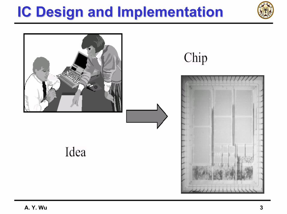
IC Design and ImplementationIC Design and Implementation
A. Y. Wu 4
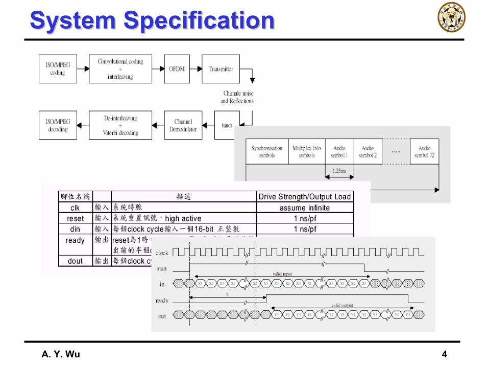
System SpecificationSystem Specification
A. Y. Wu 5
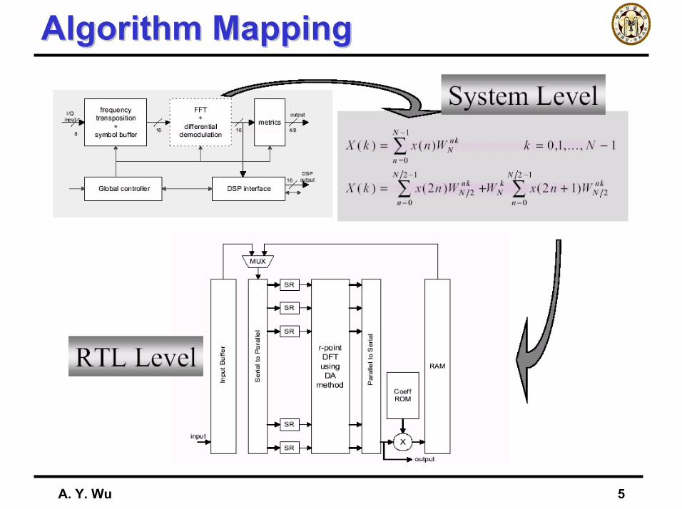
Algorithm MappingAlgorithm Mapping
A. Y. Wu 6
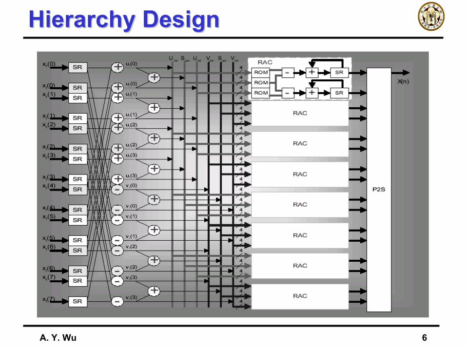
Hierarchy DesignHierarchy Design
A. Y. Wu 7
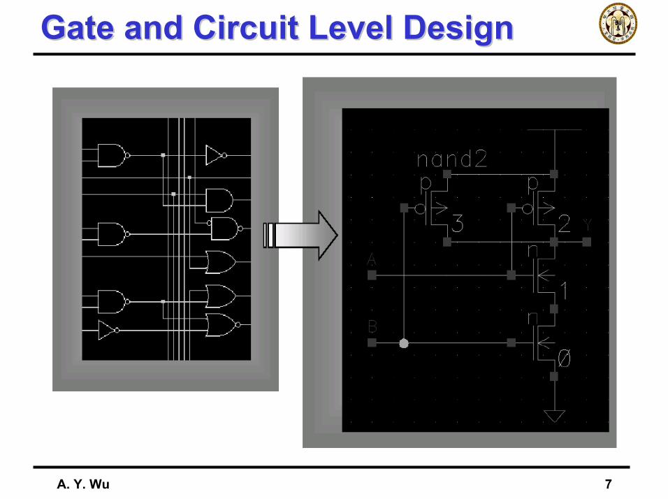
Gate and Circuit Level DesignGate and Circuit Level Design
A. Y. Wu 8
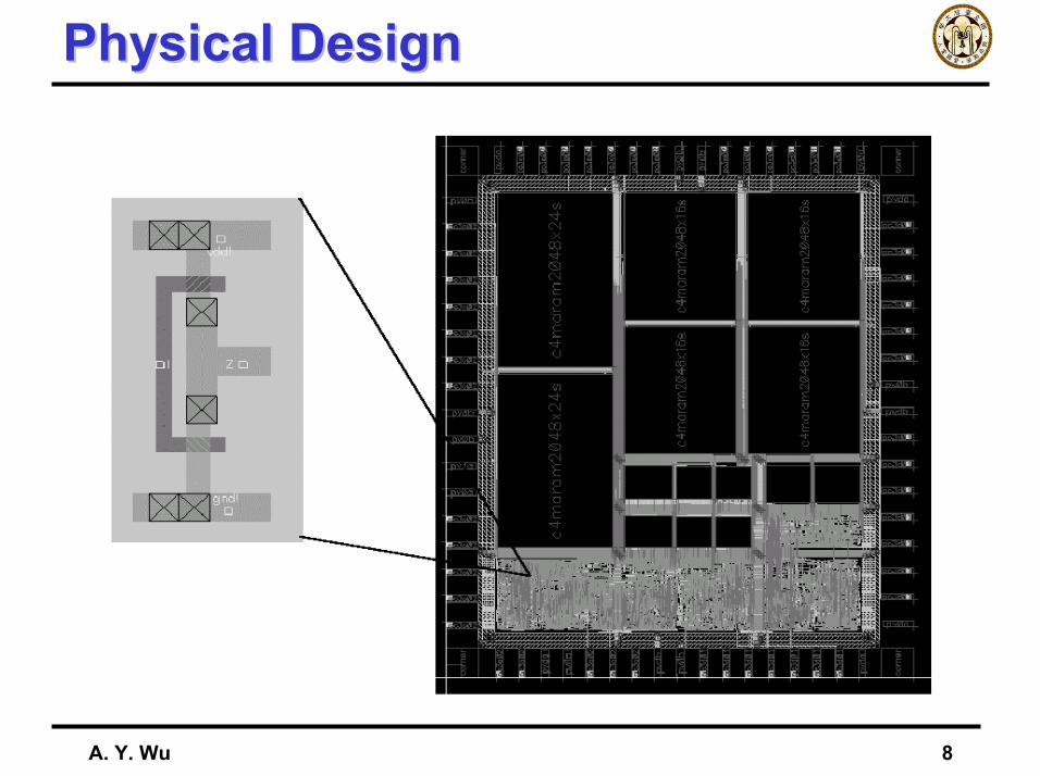
Physical DesignPhysical Design
A. Y. Wu 9
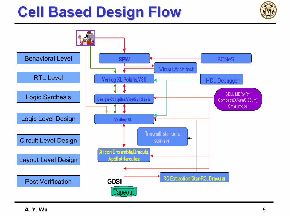
Cell Based Design FlowCell Based Design Flow
Behavioral Level
RTL Level
Logic Synthesis
Logic Level Design
Circuit Level Design
Layout Level Design
Post Verification
A. Y. Wu 10
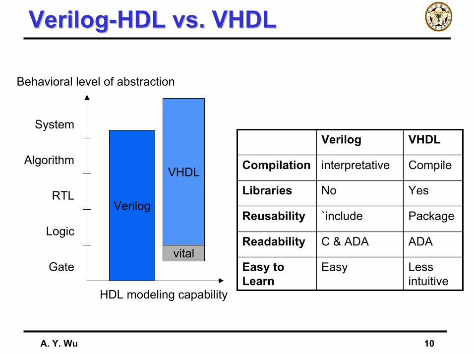
Verilog-HDL vs. VHDLVerilog-HDL vs. VHDL
HDL modeling capability
Behavioral level of abstraction
Verilog
VHDL
System
Algorithm
RTL
Logic
Gatevital
Less intuitive
EasyEasy to Learn
ADAC & ADAReadability
Package`includeReusability
YesNoLibraries
CompileinterpretativeCompilation
VHDLVerilog
A. Y. Wu 11
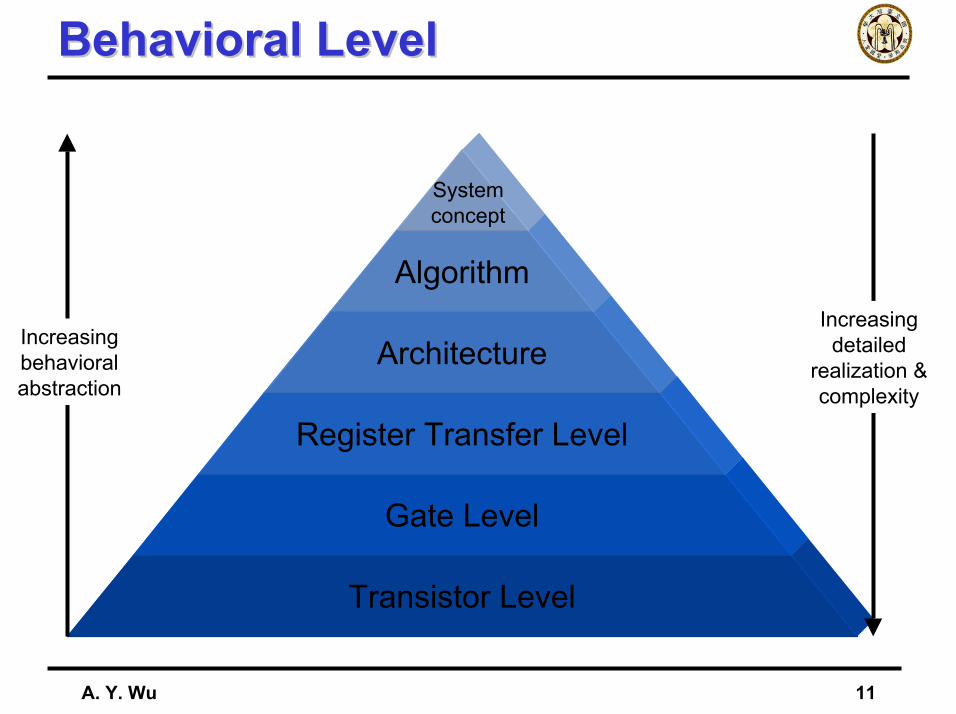
Behavioral LevelBehavioral Level
Transistor Level
Gate Level
Register Transfer Level
Architecture
Algorithm
Systemconcept
Increasingbehavioralabstraction
Increasingdetailed
realization &complexity
A. Y. Wu 12
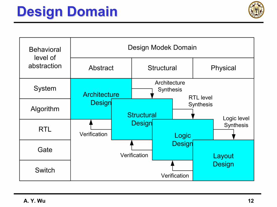
Design DomainDesign Domain
Behaviorallevel of
abstraction
Design Modek Domain
Abstract PhysicalStructural
System
Algorithm
RTL
Gate
Switch
ArchitectureDesign
StructuralDesign
LogicDesign
LayoutDesign
Verification
Verification
Verification
ArchitectureSynthesis
RTL levelSynthesis
Logic levelSynthesis
A. Y. Wu 13
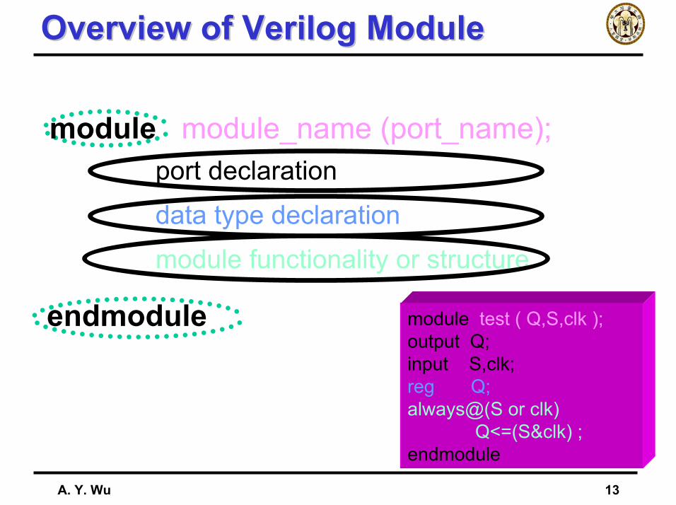
Overview of Verilog ModuleOverview of Verilog Module
port declarationdata type declarationmodule functionality or structure
module module_name (port_name);
endmodule module test ( Q,S,clk );output Q;input S,clk;reg Q;always@(S or clk)
Q<=(S&clk) ;endmodule
A. Y. Wu 14
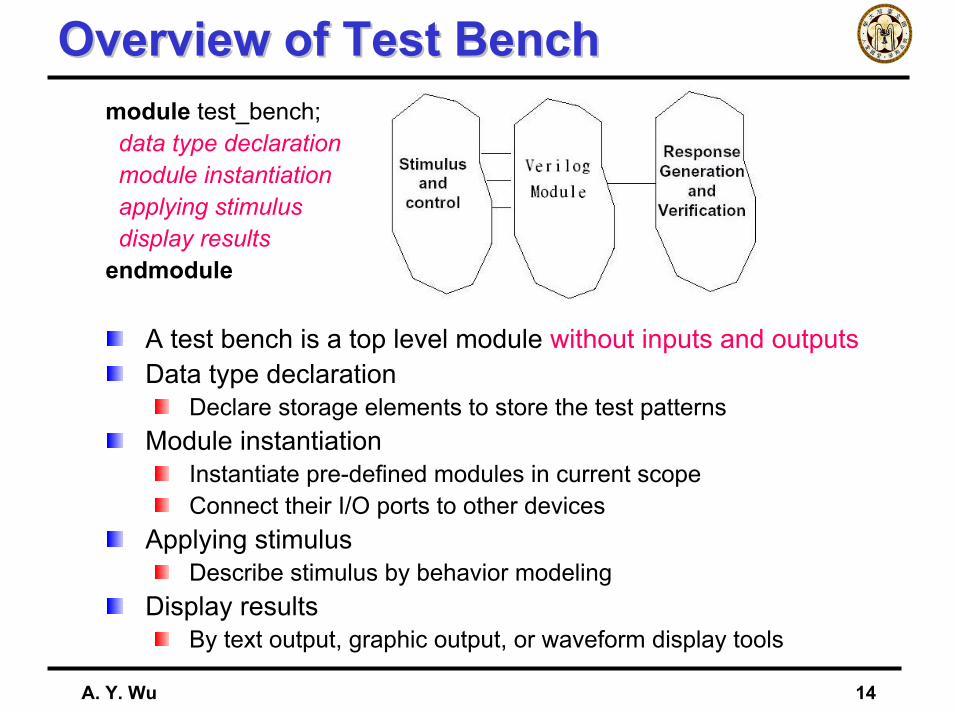
Overview of Test BenchOverview of Test Benchmodule test_bench;data type declarationmodule instantiationapplying stimulusdisplay results
endmodule
A test bench is a top level module without inputs and outputsData type declaration
Declare storage elements to store the test patternsModule instantiation
Instantiate pre-defined modules in current scopeConnect their I/O ports to other devices
Applying stimulusDescribe stimulus by behavior modeling
Display resultsBy text output, graphic output, or waveform display tools
A. Y. Wu 15
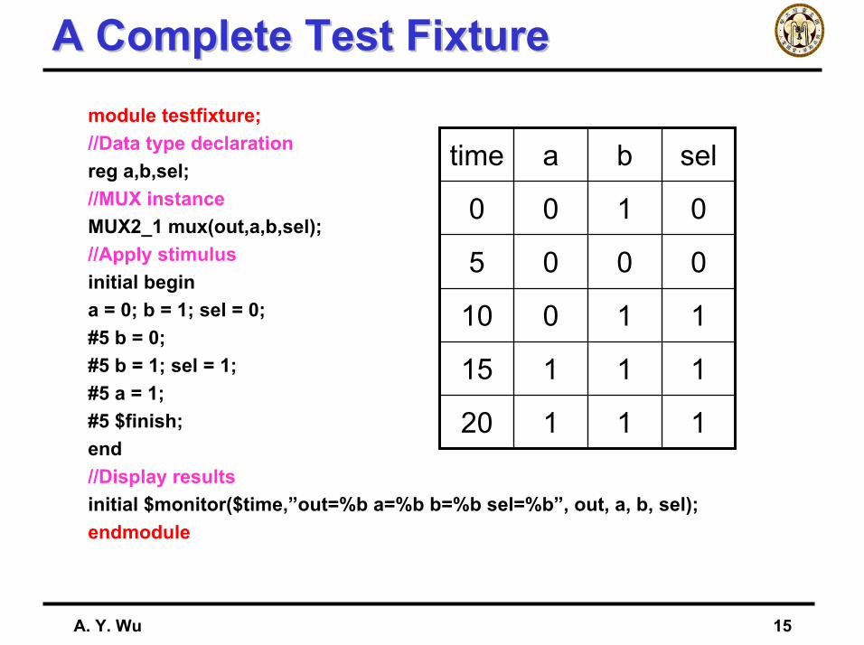
A Complete Test FixtureA Complete Test Fixturemodule testfixture;//Data type declarationreg a,b,sel;//MUX instanceMUX2_1 mux(out,a,b,sel);//Apply stimulusinitial begina = 0; b = 1; sel = 0;#5 b = 0;#5 b = 1; sel = 1;#5 a = 1;#5 $finish;end//Display resultsinitial $monitor($time,”out=%b a=%b b=%b sel=%b”, out, a, b, sel);endmodule
11120
11115
11010
0005
0100
selbatime
A. Y. Wu 16
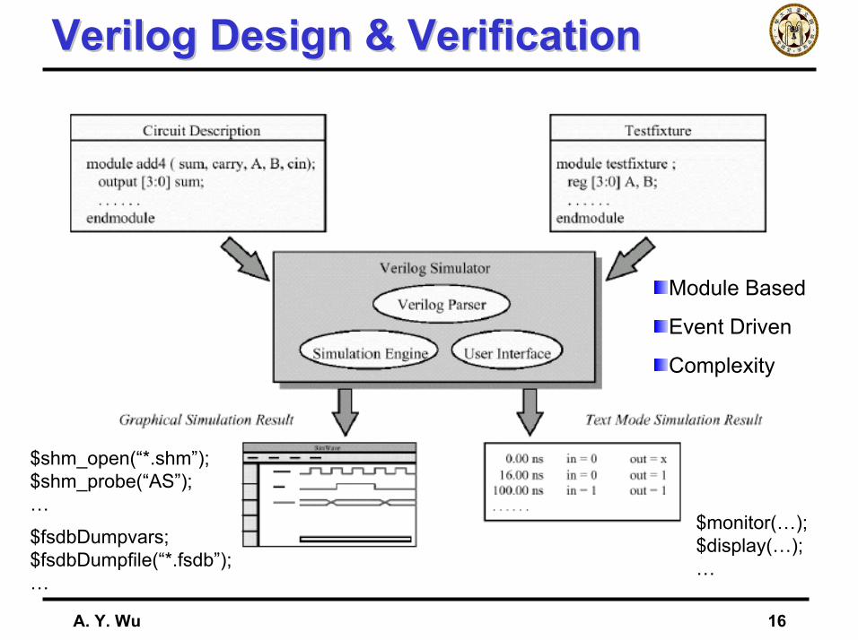
Verilog Design & VerificationVerilog Design & Verification
Module Based
Event Driven
Complexity
$monitor(…);$display(…);…
$fsdbDumpvars;$fsdbDumpfile(“*.fsdb”);…
$shm_open(“*.shm”);$shm_probe(“AS”);…
A. Y. Wu 17
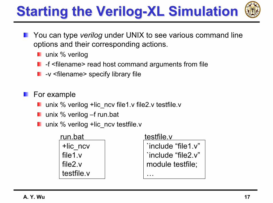
Starting the Verilog-XL SimulationStarting the Verilog-XL SimulationYou can type verilog under UNIX to see various command line options and their corresponding actions.
unix % verilog-f <filename> read host command arguments from file-v <filename> specify library file
For exampleunix % verilog +lic_ncv file1.v file2.v testfile.vunix % verilog –f run.batunix % verilog +lic_ncv testfile.v
+lic_ncvfile1.vfile2.vtestfile.v
run.bat`include “file1.v”`include “file2.v”module testfile;…
testfile.v

A. Y. Wu 18
OutlineOutline
IntroductionVerilog-HDL Circuit Design
Behavior LevelRegister-Transistor LevelGate LevelCircuit Level
SynthesisCoding Style
A. Y. Wu 19
Verilog ModuleVerilog Module
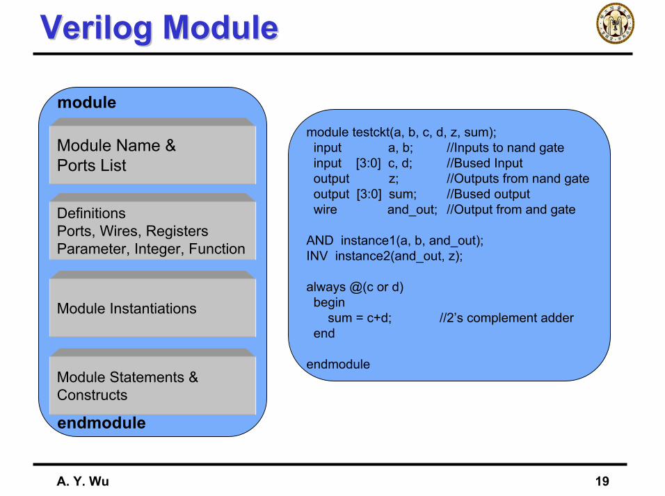
module testckt(a, b, c, d, z, sum);input a, b; //Inputs to nand gateinput [3:0] c, d; //Bused Inputoutput z; //Outputs from nand gateoutput [3:0] sum; //Bused outputwire and_out; //Output from and gate
AND instance1(a, b, and_out);INV instance2(and_out, z);
always @(c or d)begin
sum = c+d; //2’s complement adderend
endmodule
Module Name &Ports List
DefinitionsPorts, Wires, RegistersParameter, Integer, Function
Module Instantiations
Module Statements &Constructs
module
endmodule
A. Y. Wu 20
Recall Verilog StructureRecall Verilog Structure
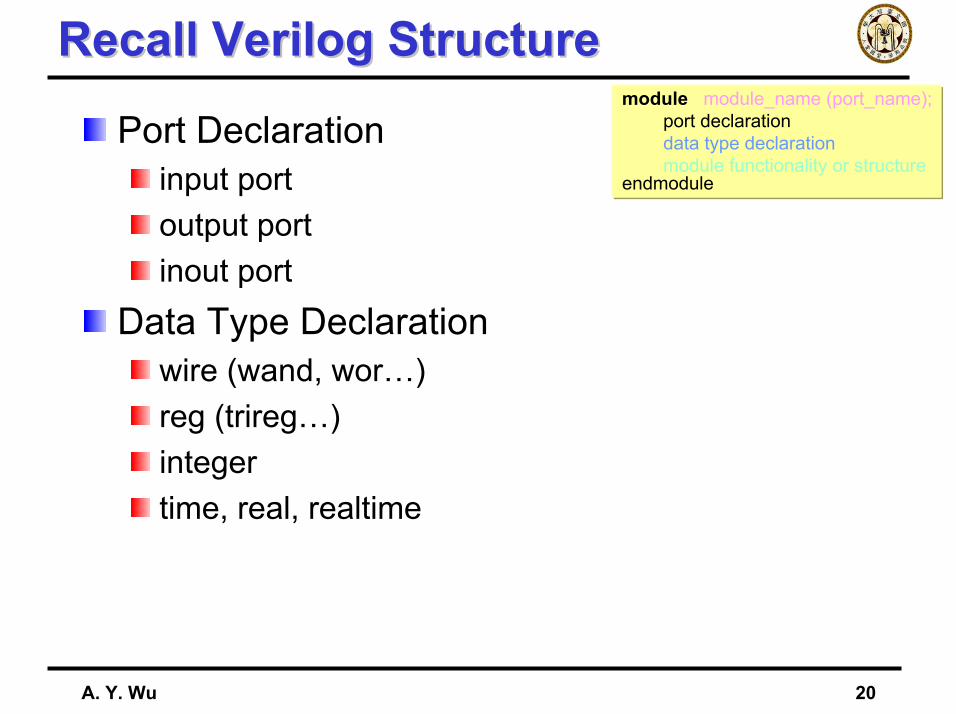
Port Declarationinput portoutput portinout port
Data Type Declarationwire (wand, wor…)reg (trireg…)integertime, real, realtime
module module_name (port_name);port declarationdata type declarationmodule functionality or structure
endmodule
A. Y. Wu 21
wire & regwire & regwire(wand, wor, tri)
Physical wires in a circuitCannot assign a value to a wire within a function or a begin…end blockA wire does not store its value, it must be driven by
—by connecting the wire to the output of a gate or module—by assigning a value to the wire in a continuous assignment
An undriven wire defaults to a value of Z(high impedance)input, output, inout port declaration—wire data type(default)
regA variable in VerilogUse of “reg” data type not exactly synthesized to really register
A. Y. Wu 22
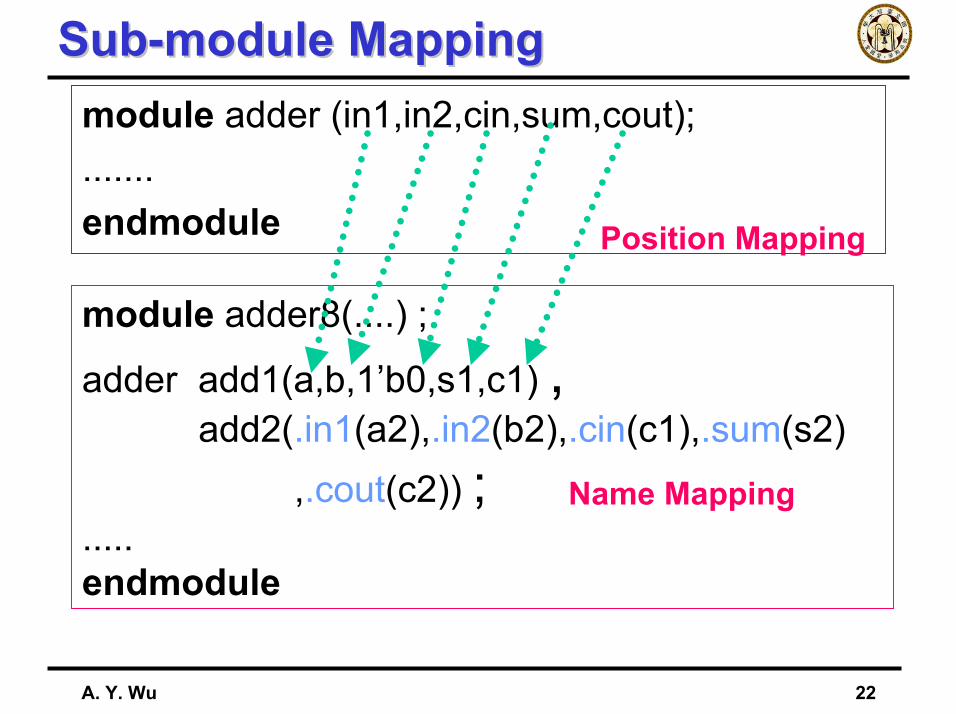
Sub-module MappingSub-module Mappingmodule adder (in1,in2,cin,sum,cout);.......endmodule
module adder8(....) ;
adder add1(a,b,1’b0,s1,c1) ,add2(.in1(a2),.in2(b2),.cin(c1),.sum(s2)
,.cout(c2)) ;.....endmodule
Position Mapping
Name Mapping
A. Y. Wu 23
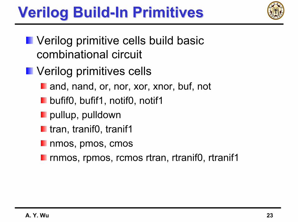
Verilog Build-In PrimitivesVerilog Build-In Primitives
Verilog primitive cells build basic combinational circuitVerilog primitives cells
and, nand, or, nor, xor, xnor, buf, notbufif0, bufif1, notif0, notif1pullup, pulldowntran, tranif0, tranif1nmos, pmos, cmosrnmos, rpmos, rcmos rtran, rtranif0, rtranif1
A. Y. Wu 24
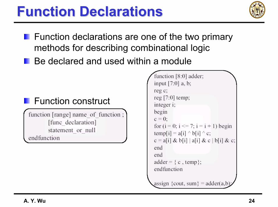
Function DeclarationsFunction DeclarationsFunction declarations are one of the two primary methods for describing combinational logicBe declared and used within a module
Function construct
A. Y. Wu 25
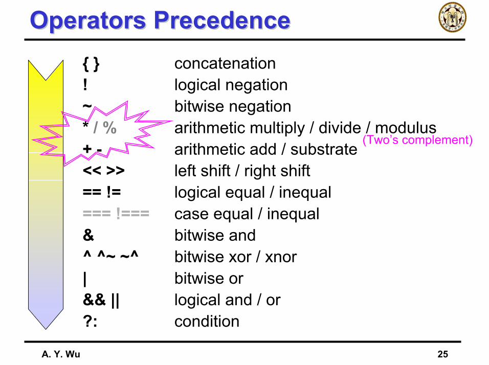
Operators PrecedenceOperators Precedence{ } concatenation! logical negation~ bitwise negation* / % arithmetic multiply / divide / modulus+ - arithmetic add / substrate<< >> left shift / right shift== != logical equal / inequal=== !=== case equal / inequal& bitwise and^ ^~ ~^ bitwise xor / xnor| bitwise or&& || logical and / or?: condition
(Two’s complement)
A. Y. Wu 26
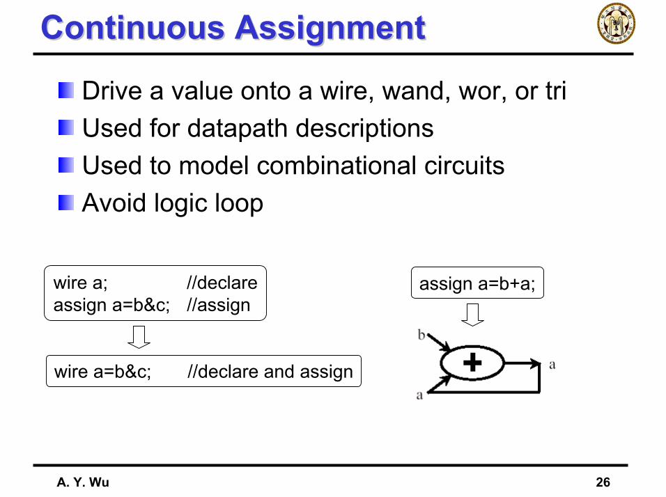
Continuous AssignmentContinuous Assignment
Drive a value onto a wire, wand, wor, or triUsed for datapath descriptionsUsed to model combinational circuitsAvoid logic loop
wire a; //declareassign a=b&c; //assign
wire a=b&c; //declare and assign
assign a=b+a;
A. Y. Wu 27
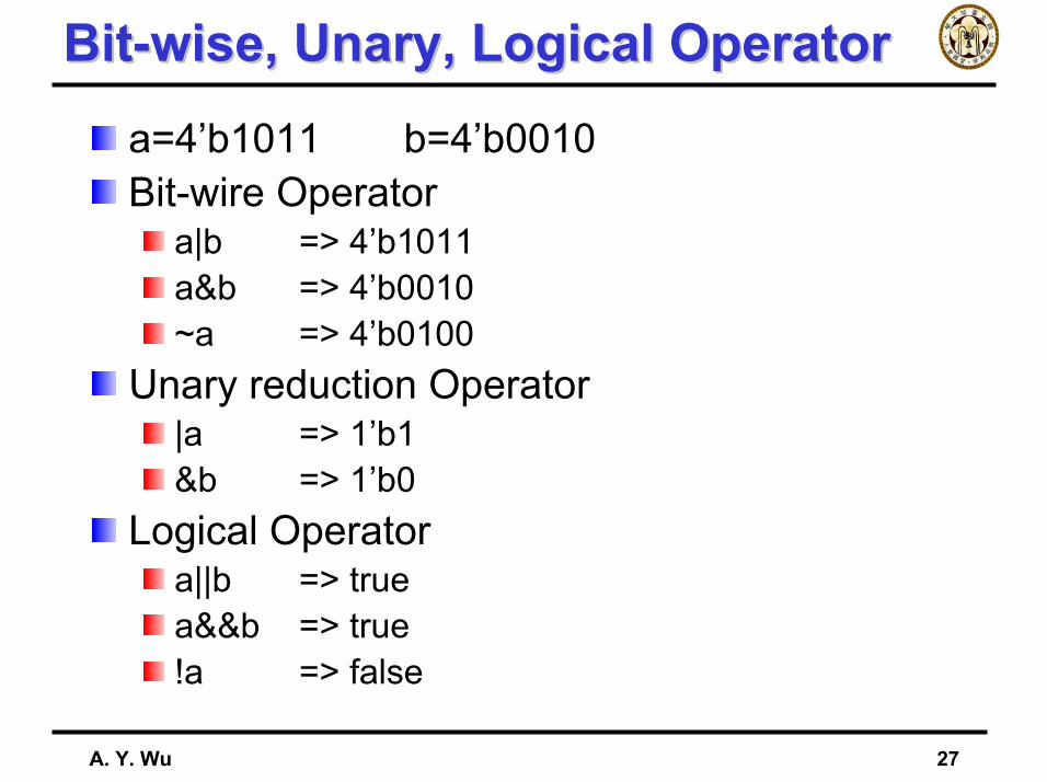
Bit-wise, Unary, Logical OperatorBit-wise, Unary, Logical Operatora=4’b1011 b=4’b0010Bit-wire Operator
a|b => 4’b1011a&b => 4’b0010~a => 4’b0100
Unary reduction Operator|a => 1’b1&b => 1’b0
Logical Operatora||b => truea&&b => true!a => false
A. Y. Wu 28
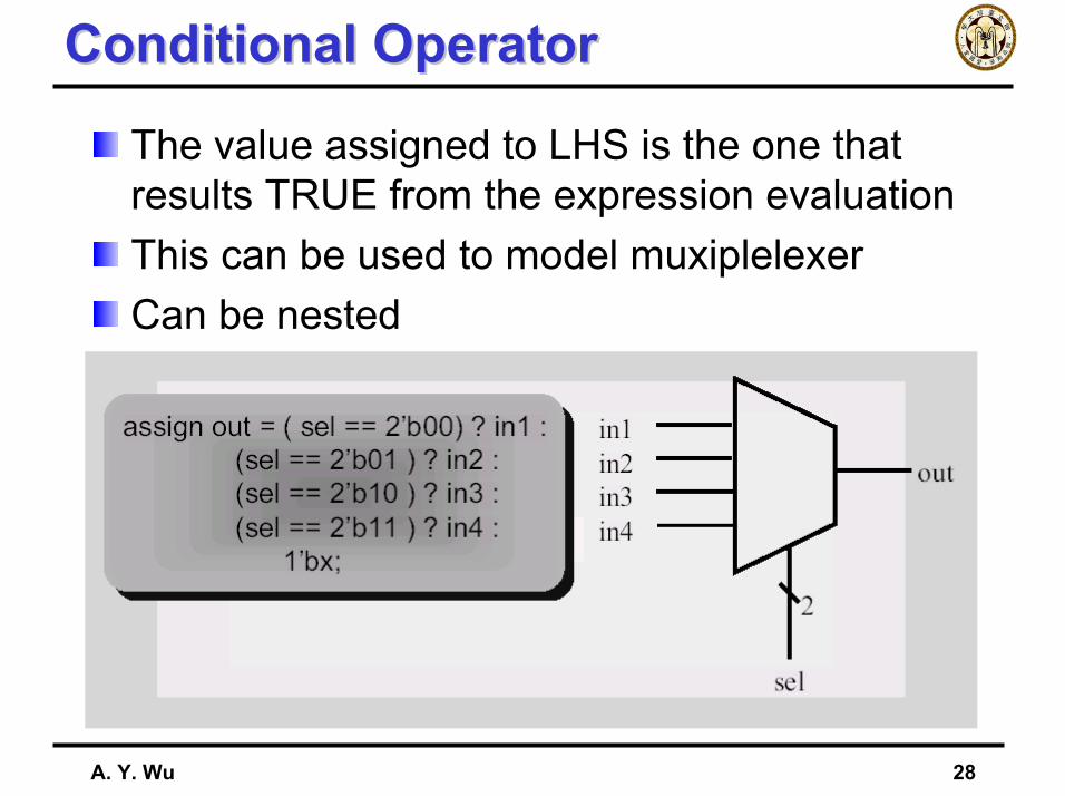
Conditional OperatorConditional Operator
The value assigned to LHS is the one that results TRUE from the expression evaluationThis can be used to model muxiplelexerCan be nested
A. Y. Wu 29
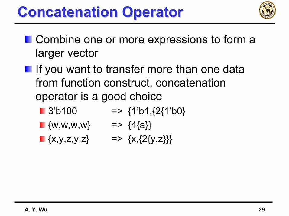
Concatenation OperatorConcatenation Operator
Combine one or more expressions to form a larger vectorIf you want to transfer more than one data from function construct, concatenation operator is a good choice
3’b100 => {1’b1,{2{1’b0}{w,w,w,w} => {4{a}}{x,y,z,y,z} => {x,{2{y,z}}}
A. Y. Wu 30
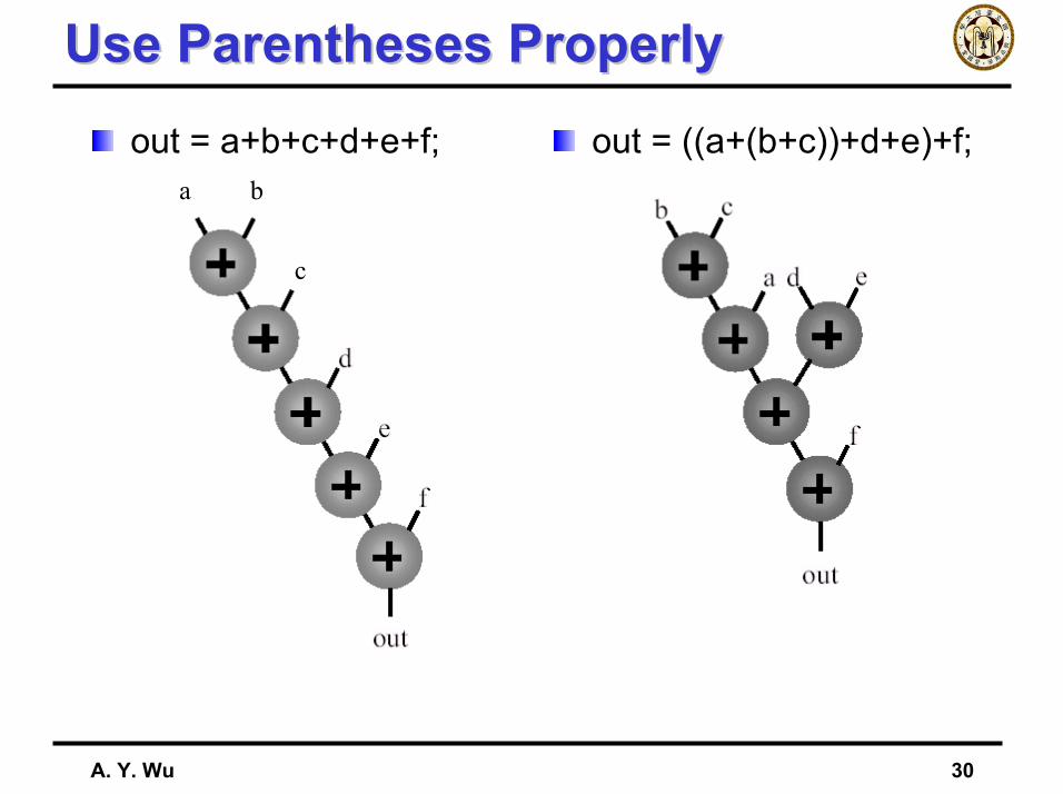
Use Parentheses ProperlyUse Parentheses Properlyout = a+b+c+d+e+f; out = ((a+(b+c))+d+e)+f;
a b
c
A. Y. Wu 31
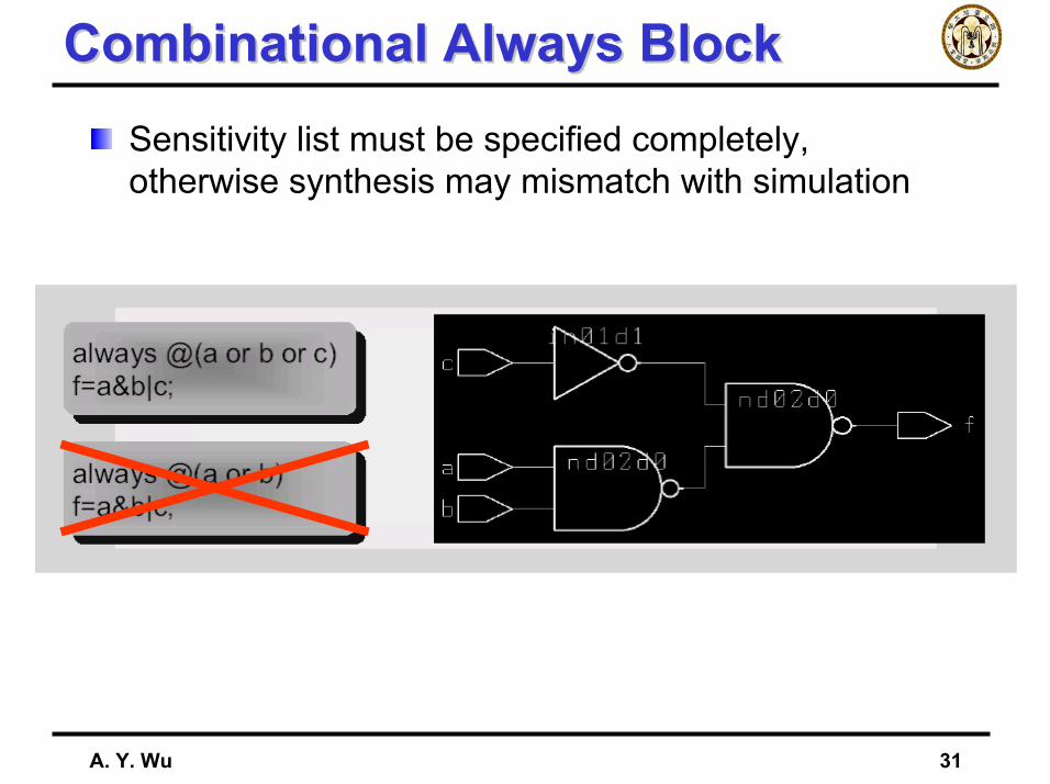
Combinational Always BlockCombinational Always BlockSensitivity list must be specified completely, otherwise synthesis may mismatch with simulation
A. Y. Wu 32
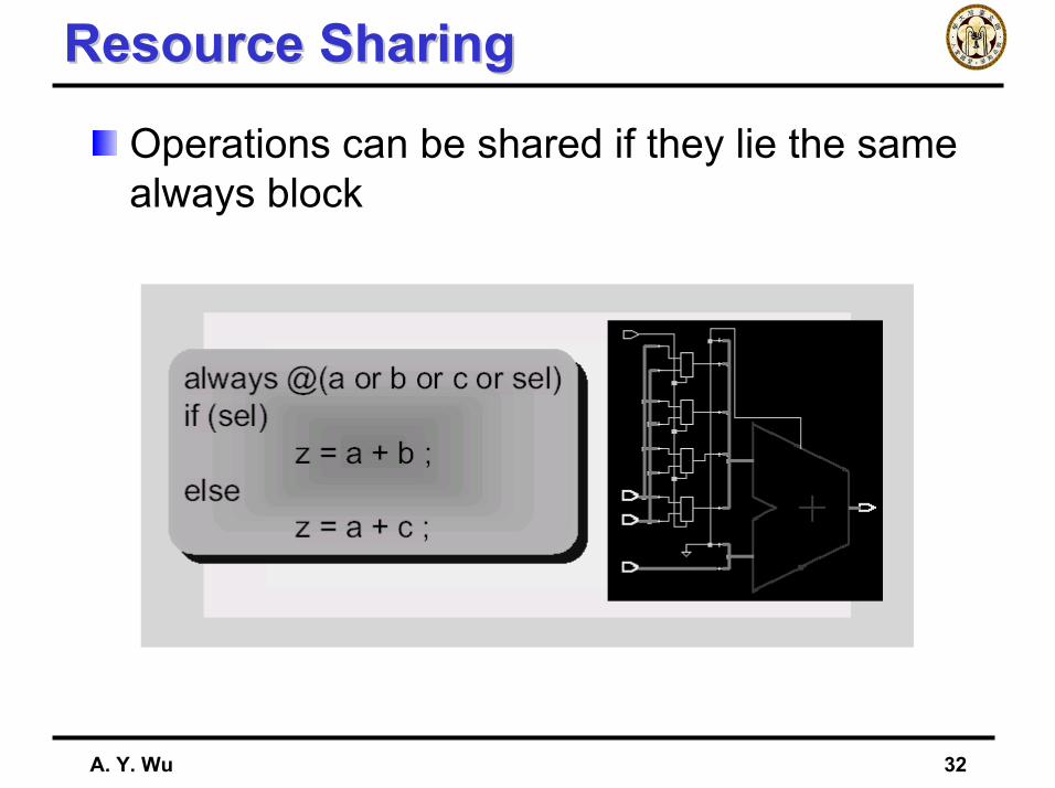
Resource SharingResource Sharing
Operations can be shared if they lie the same always block
A. Y. Wu 33
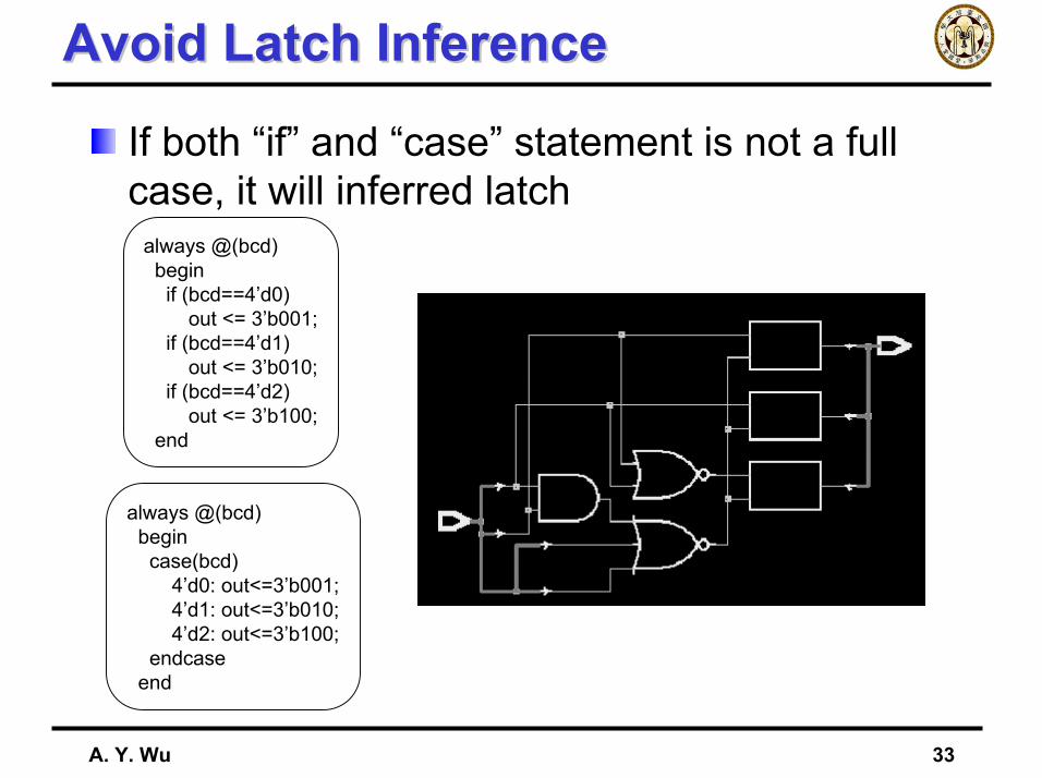
Avoid Latch InferenceAvoid Latch Inference
If both “if” and “case” statement is not a full case, it will inferred latch
always @(bcd)begin
case(bcd)4’d0: out<=3’b001;4’d1: out<=3’b010;4’d2: out<=3’b100;
endcaseend
always @(bcd)begin
if (bcd==4’d0)out <= 3’b001;
if (bcd==4’d1)out <= 3’b010;
if (bcd==4’d2)out <= 3’b100;
end
A. Y. Wu 34
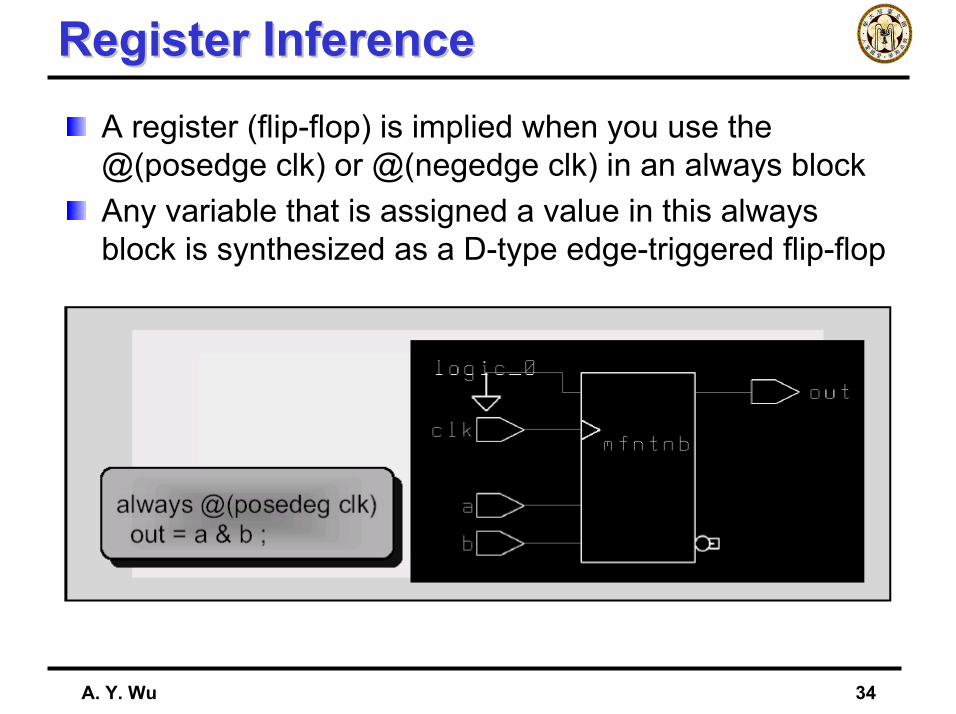
Register InferenceRegister InferenceA register (flip-flop) is implied when you use the @(posedge clk) or @(negedge clk) in an always blockAny variable that is assigned a value in this always block is synthesized as a D-type edge-triggered flip-flop

A. Y. Wu 35
Separate Comb. & Seq. AssignmentSeparate Comb. & Seq. Assignment
always @(posedge clk)beginif (en)out = in;
elseout = 1’bz;
end
always @(posedge clk)temp = in;
always @(posedge clk)beginif (en) out = temp;else out = 1’bz;
end
A. Y. Wu 36
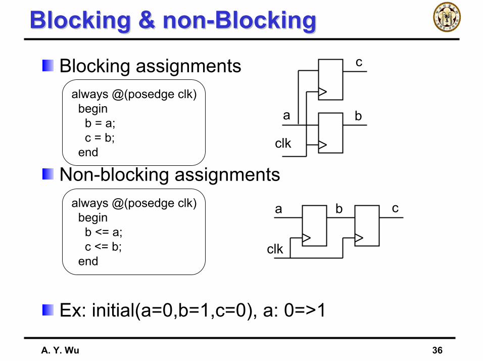
Blocking & non-BlockingBlocking & non-Blocking
Blocking assignments
Non-blocking assignments
Ex: initial(a=0,b=1,c=0), a: 0=>1
always @(posedge clk)beginb = a;c = b;
end
always @(posedge clk)beginb <= a;c <= b;
end
a
clk
b c
a
clk
b
c
A. Y. Wu 37
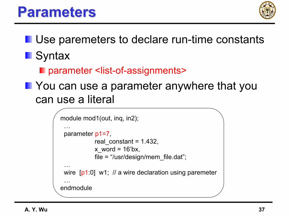
ParametersParameters
Use paremeters to declare run-time constantsSyntax
parameter <list-of-assignments>You can use a parameter anywhere that you can use a literal
module mod1(out, inq, in2);…parameter p1=7,
real_constant = 1.432,x_word = 16’bx,file = “/usr/design/mem_file.dat”;
…wire [p1:0] w1; // a wire declaration using paremeter…
endmodule
A. Y. Wu 38
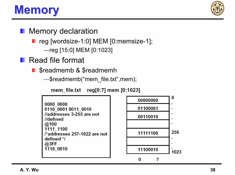
MemoryMemoryMemory declaration
reg [wordsize-1:0] MEM [0:memsize-1];—reg [15:0] MEM [0:1023]
Read file format$readmemb & $readmemh
—$readmemb(“mem_file.txt”,mem);
A. Y. Wu 39
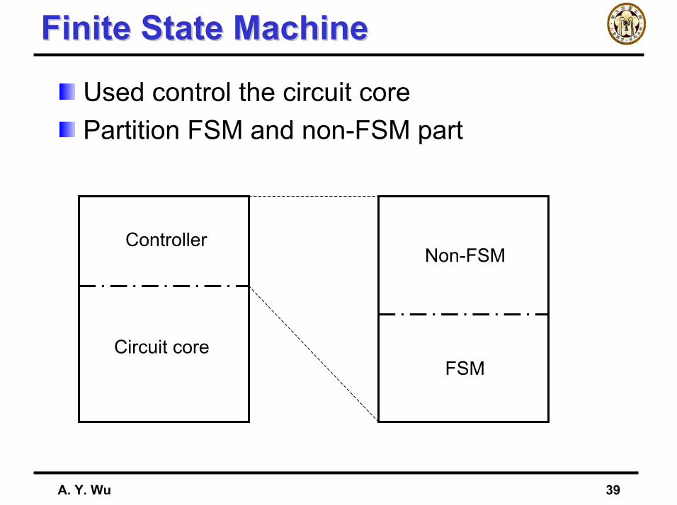
Finite State MachineFinite State Machine
Used control the circuit corePartition FSM and non-FSM part
Controller
Circuit core
Non-FSM
FSM
A. Y. Wu 40
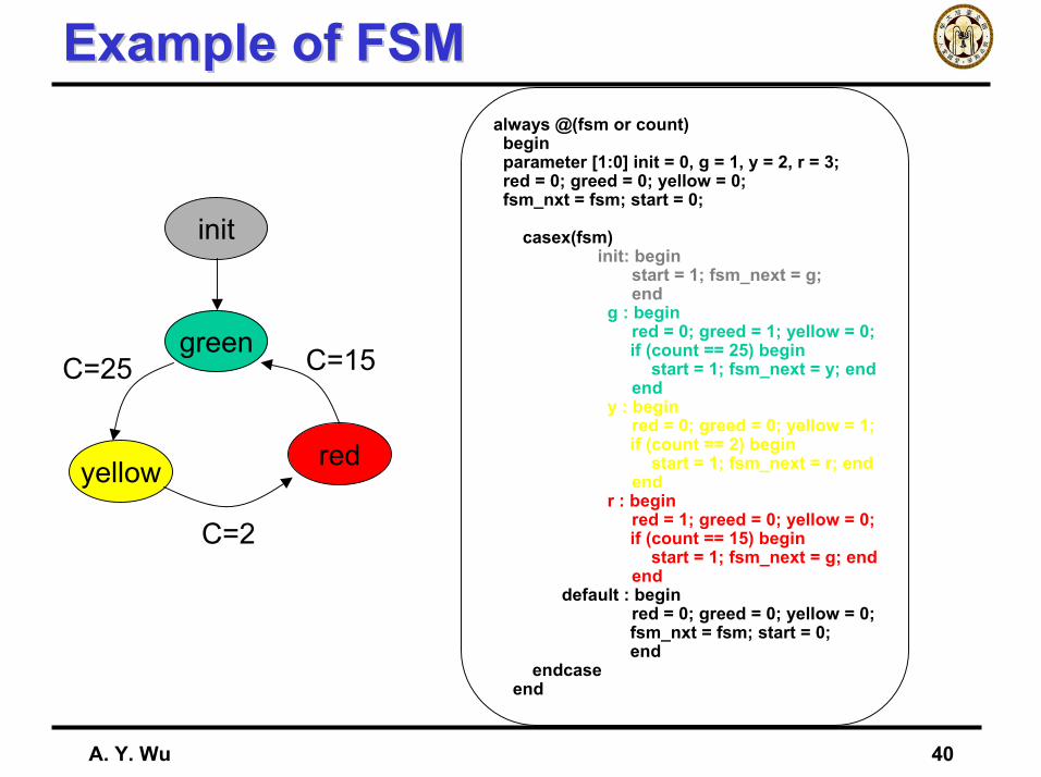
Example of FSMExample of FSM
init
green
yellow red
C=25 C=15
C=2
always @(fsm or count)beginparameter [1:0] init = 0, g = 1, y = 2, r = 3;red = 0; greed = 0; yellow = 0;fsm_nxt = fsm; start = 0;
casex(fsm)init: begin
start = 1; fsm_next = g;end
g : beginred = 0; greed = 1; yellow = 0;if (count == 25) begin
start = 1; fsm_next = y; endend
y : beginred = 0; greed = 0; yellow = 1;if (count == 2) begin
start = 1; fsm_next = r; endend
r : beginred = 1; greed = 0; yellow = 0;if (count == 15) begin
start = 1; fsm_next = g; endend
default : beginred = 0; greed = 0; yellow = 0;fsm_nxt = fsm; start = 0;end
endcaseend

A. Y. Wu 41
OutlineOutline
IntroductionVerilog-HDL Circuit Design
Behavior LevelRegister-Transistor LevelGate LevelCircuit Level
SynthesisCoding Style
A. Y. Wu 42
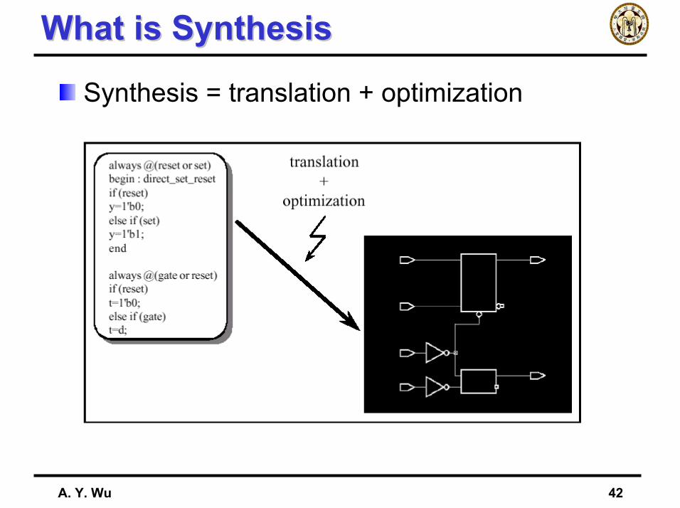
What is SynthesisWhat is Synthesis
Synthesis = translation + optimization
A. Y. Wu 43
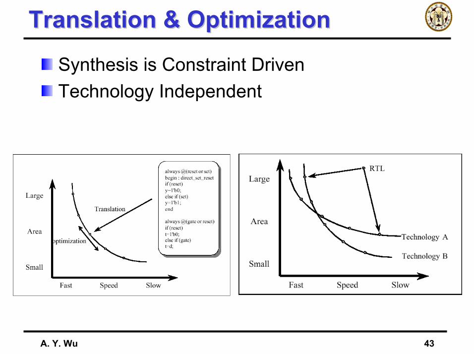
Translation & OptimizationTranslation & Optimization
Synthesis is Constraint DrivenTechnology Independent
A. Y. Wu 44
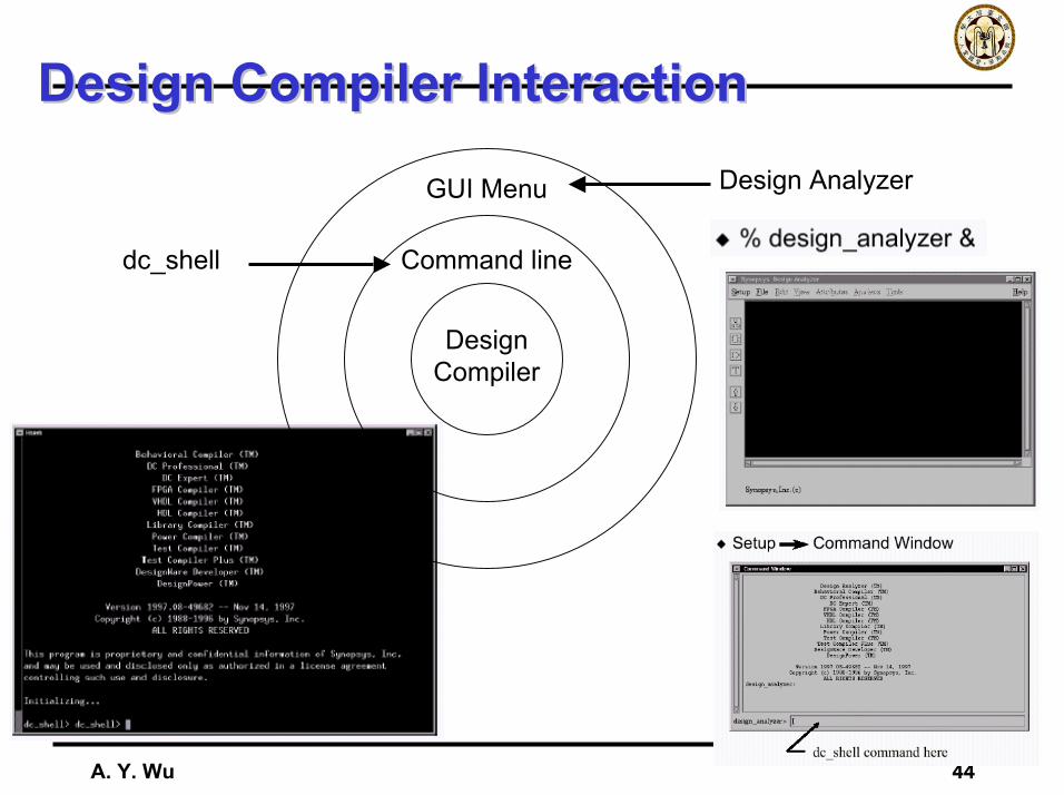
Design Compiler InteractionDesign Compiler Interaction
DesignCompiler
Command line
GUI Menu Design Analyzer
dc_shell
A. Y. Wu 45
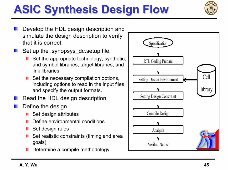
ASIC Synthesis Design FlowASIC Synthesis Design FlowDevelop the HDL design description and simulate the design description to verify that it is correct.Set up the .synopsys_dc.setup file.
Set the appropriate technology, synthetic, and symbol libraries, target libraries, and link libraries.Set the necessary compilation options, including options to read in the input files and specify the output formats.
Read the HDL design description.Define the design.
Set design attributesDefine environmental conditionsSet design rulesSet realistic constraints (timing and area goals)Determine a compile methodology
A. Y. Wu 46
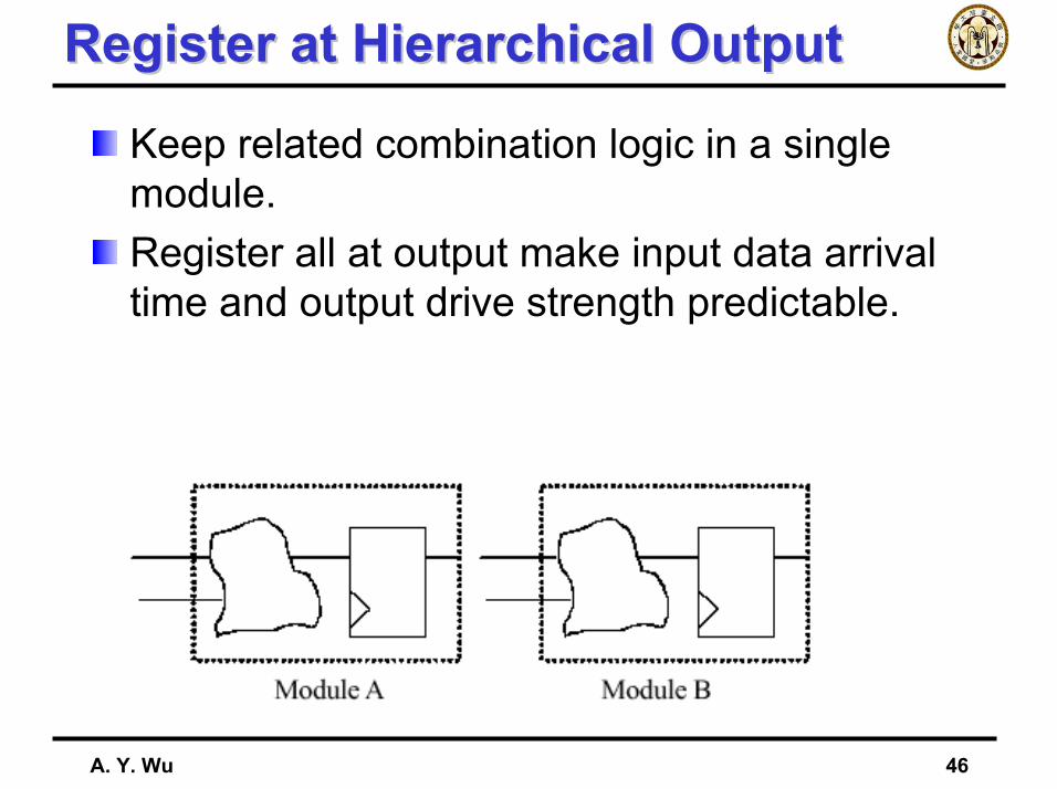
Register at Hierarchical OutputRegister at Hierarchical Output
Keep related combination logic in a single module.Register all at output make input data arrival time and output drive strength predictable.
A. Y. Wu 47
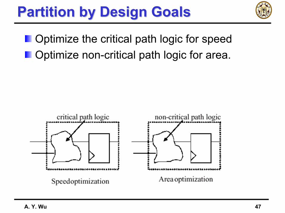
Partition by Design GoalsPartition by Design Goals
Optimize the critical path logic for speedOptimize non-critical path logic for area.
A. Y. Wu 48
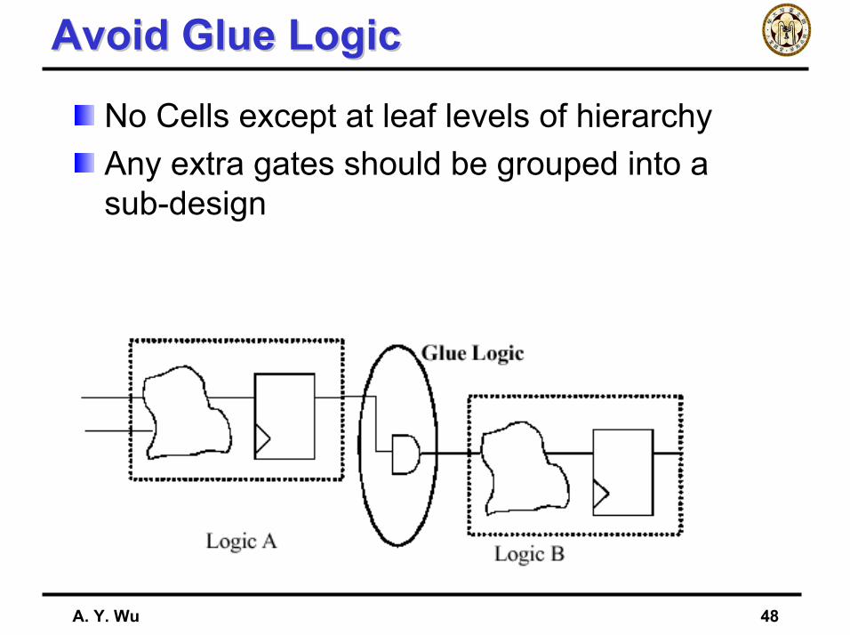
Avoid Glue LogicAvoid Glue Logic
No Cells except at leaf levels of hierarchyAny extra gates should be grouped into a sub-design

A. Y. Wu 49
OutlineOutline
IntroductionVerilog-HDL Circuit Design
Behavior LevelRegister-Transistor LevelGate LevelCircuit Level
SynthesisCoding Style
A. Y. Wu 50
Principles of RTL Coding StylesPrinciples of RTL Coding Styles
ReadabilitySimplicityLocalityPortabilityReusabilityReconfigurability
A. Y. Wu 51
File HeaderFile Header
Should be included for all source filesContents
author informationrevision historypurpose descriptionavailable parametersreset scheme and clock domaincritical timing and asynchronous interfacetest structure
A corporation-wide standard template
A. Y. Wu 52
Naming ConventionsNaming ConventionsLowercase letters for signal namesUppercase letters for constantsCase-insensitive namingUse clk for clocks, rst for resetsSuffixes
_n for active-low_a for async_z for tri-state
Identical names for connected signals and portsDo not use HDL reserved wordsConsistency within group, division and corporation
A. Y. Wu 53
PortsPorts
OrderingOne port per line with appropriate commentsInputs first then outputsClocks, resets, enables, other controls, address bus, then data bus…
MappingUsed named mapping instead of positionalmapping
A. Y. Wu 54
Coding PracticesCoding Practices
Little-ending for multi-bit busOperand sizes should matchExpression in condition must be a 1-bit valueUse parentheses in complex statementsDo not assign signals don’t case valueReset all storage elements
A. Y. Wu 55
PortabilityPortability
Do not use hard-coded numbersAvoid embedded synthesis scriptsUse technology-independent librariesAvoid instantiating gates
A. Y. Wu 56
Clocks and ResetsClocks and Resets
Simple clocking is easier to understand, analyze, and maintainAvoid using both edges of the clock
Duty-cycle sensitiveDifficult DFT process
Do not buffer clock and reset networksAvoid gated clockAvoid internally generated clock and resets
Limited testability
A. Y. Wu 57
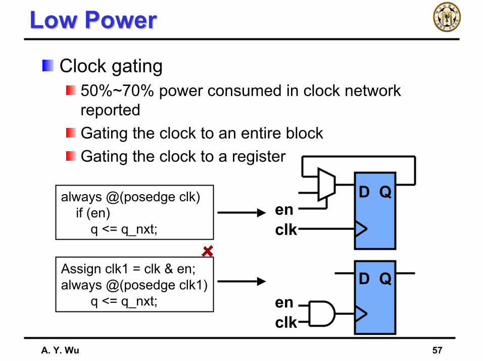
Low PowerLow Power
Clock gating50%~70% power consumed in clock network reportedGating the clock to an entire blockGating the clock to a register
always @(posedge clk)if (en)
q <= q_nxt;
Assign clk1 = clk & en;always @(posedge clk1)
q <= q_nxt;
D Q
D Q
clk
clken
en
A. Y. Wu 58
SynchronicitySynchronicity
Infer technology-independent registers(positive) single edge-triggered registers
Avoid latches intentionallyExcept for small memory and FIFO
Avoid latches unintentionallyAvoid incomplete assignment in case statementUse default assignmentsAvoid incomplete if-then-else chain
Avoid combinational feedback loopsSTA and ATPG problem
A. Y. Wu 59
Combinational and SequentialCombinational and Sequential
Combinational blockUse blocking assignments (=)Minimize signals required in sensitivity listAssignment should be applied in topological order
Sequential blockUse non-blocking assignments (<=)Avoid race problems in simulation
Com./Seq. logic should be separated
A. Y. Wu 60
Coding for SynthesisCoding for SynthesisSpecify complete but no redundant sensitivity lists
Simulation coherenceSimulation speed
If-then-else often infers a cascaded encoderInputs signals with different arrival time
Case infers a single-level muxCase is better if priority encoding is not requiredCase is generally simulated faster then if-then-else
Conditional assignments (?:)Infer a mux, with slower simulation performance
A. Y. Wu 61
Coding for SynthesisCoding for Synthesis
FSMPartition FSM and non-FSM logicPartition combinational part and sequential partUse parameter to define names of the state vectorAssign a default (reset) state
No # delay statementsUse full_case and parallel_case judiciouslyExplicitly declare wiresAvoid glue logic at the top-levelAvoid expressions in port connections
A. Y. Wu 62
PartitioningPartitioningRegister all outputs
Make output drive strengths and input delay predictableEase time budgeting and constraints
Keep related logic togetherImprove synthesis quality
Partition logic with different design goalsAvoid asynchronous logic
Technology dependentMore difficult to ensure correct functionality and timingAs small as possible and isolation
Keep sharable resources in the same block
National Taiwan University
Q&AQ&A