national research council of canada f/g i/2 evaleuations of helicopter instrument ... · ·...
TRANSCRIPT

ADAuG4 004 NATIONAL RESEARCH COUNCIL OF CANADA OTTAWA (ONTARIO) F/G i/2EVALEUATIONS OF HELICOPTER INSTRUMENT-FLIGHT HANDLING QUALITIES --ETC(U(AJAN 82 S R SINCLAIR, S KERELIUK
CLASSIINRCC-LR-608 NL
E~ihEEEE-miEEEEEglglgEElggEEIIiEEEEEEll

SI€ National Research Conseil nationalCouncil Canada de recherches Canada
EVALUATIONS OF HELICOPTERINSTRUMENT- FLIGHTHANDLING QUALITIES
byS.R.M. Sinclair, S. Iereliuk
National Aeronautical Establishment
OTTAWA
JANUARY 1982 2 "b
CL-,__jmTK .'UTION A.TE... A
"Approved for public release;Dhtution Unlimited
2 ,DtAERONAUTICAL REPORT
Canada LR608SZ ' V "NRC NO. 19991

EVALUATIONS OF HELICOPTER INSTRUMENT -FLIGHT HANDLING QUALITIES
EVALUATION DE LA MANIABILITE DES HELICOPTERES
POUR LE VOL AUX INSTRUMENTS
by/par
S.R.M. Sinclair, S. Kereliuk
DIU13T 1 STATEMbf AS.R.M. Sinclair, Head/Chef Apprewed tot pubUC ',"oamFlight Research Laboratory/ Ditributi'm Unlnimted G.M. LindbergLaboratoire des recherches en vol Director/Directeur

SUMMARY
The NAE Airborne Simulator, a modified and suitably equippedBell 205A helicopter, was used in experiments to provide background inf or-mation on the handling qualities requirements for helicopter instrumentflight. This investigation was in support of a regulatory review undertakenby the U.S. Federal Aviation Administration as part of an overall assessmentof the helicopter certification process.
The results illustrate the inter-dependence of the various stabilityand control characteristics which contribute to safe instrument flight handlingqualities, and underline the importance of good mission simulation in con-ducting certification-related experiments.
SOMMAIRE
Le simulateur airoport,6 EAN, un Bell 205A modifi6 et convenable-mant 6quip6, a servi de sujet d'exp~rience pour diterminer las caract~ristiquesessentielles de maniabilit6 des h6licoptires pour le vol aux instruments. Ces6tudes s'inscrivent dans la revue de la r~glementation entreprise par laFederal Aviation Administration des E.-U. dans son evaluation g~n6rale desm~thodes de certification des h6licopthres.
Les resultats r6vilent l'interd~pendance des diverses caract~ris-tiques de stabiliti- at de contr6le qui contribuent i assurer une maniabilit,6sure pour la vol aux instruments. En outre, ils font ressortir l'importance deproc&Jer a des vols simul~s convenables pour les experiences reli~es i lacertification des b6licoptkres.

CONTENTS
Page
SUM M ARY ........................................................... (iii)
1.0 INTRODUCTION ...................................................... 1
2.0 THE AIRBORNE SIMULATOR ........................................... 2
3.0 M ODELLING ......................................................... 3
4.0 EXPERIMENTAL PROCEDURES ......................................... 3
5.0 THE FLIGHT EXPERIMENTS ............................................ 5
5.1 The First Experiment ............................................... 55.2 The Second Experiment ............................................. 65.3 The Third Experiment ............................................... 7
6.0 CONCLUDING REMARKS .............................................. 9
7.0 ACKNOWLEDGEMENT ................................................. 9
8.0 REFERENCES ........................................................ 9
TABLES
Table Page
1 Description of Models Used in the First Experiment ........................ 11
2 Description of Models Used in the Second Experiment ...................... 12
3 Description of Models Used in the Third Experiment ....................... 13
4 Flying Experience and Project Involvement of the Evaluation Pilots ............ 14
5 Summary of Mission Assessments ...................................... 14
ILLUSTRATIONS
Figure Page
1 NAE Airborne Simulator ............................................. 15
2 Evaluation Cockpit ................................................. 16
3 Effects of Combining Mu and M Augmentation .......................... 17
4 Effects of Combining Mu and Mq Augmentation .......................... 18
(iv)

ILLUSTRATIONS (Cont'd)
Figure Page
5 MLS Terminal Procedure ............................................... 19
6(a) Dual - Pilot Task .................................................... 20
6(b) Single - Pilot Task ................................................... 21
7 Sample MLS Approach Plate ............................................ 22
8 Pilot Questionnaire ................................................... 23
9 Flight Test Routine ................................................... 25
10(a) Model 1 - Longitudinal Dynamic Response ................................ 26
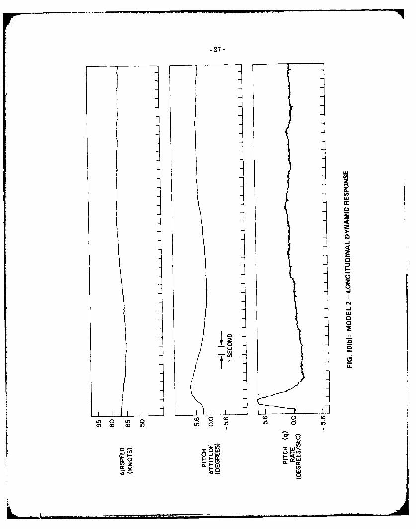
10(b) Model 2 - Longitudinal Dynamic Response ................................ 27
10(c) Model 3 - Longitudinal Dynamic Response ................................ 28
10(d) Model 2A - Longitudinal Dynamic Response ............................... 29
11(a) Certification Assessments .............................................. 30
11(b) Certification Assessments .............................................. 31
11(c) Certification Assessments .............................................. 32
11(d) Certification Assessments .............................................. 33
11(e) Certification Assessments .............................................. 34
11(f) Certification Assessments .............................................. 35
11(g) Certification Assessments .............................................. 36
11(h) Certification Assessments .............................................. 37
12(a) Cooper-Harper Ratings for Evaluated Models ............................... 38
12(b) Cooper-Harper Ratings for Evaluated Models ............................... 39
12(c) Cooper-Harper Ratings for Evaluated Models ............................... 40
12(d) Cooper-Harper Ratings for Evaluated Models ............................... 41
12(e) Cooper-Harper Ratings for Evaluated Models ............................... 42
12(f) Cooper-Harper Ratings for Evaluated Models ............................... 43
(v)
-1-
EVALUATIONS OF HELICOPTER INSTRUMENT-FLIGHT HANDLING QUALITIES
1.0 INTRODUCTION
Although the first civil IFR certification for a helicopter was granted by the Federal AviationAgency in 1960, it is only in very recent years that a strong demand has developed for all-weathercapability in civil helicopter operations. The helicopter manufacturers have responded to this demand,first with a series of retro-fit instrument flight systems for helicopter types which have already beenapproved for visual-flight, and more recently with a new generation of helicopters designed for theinstrument flight environment.
The introduction of these new systems and aircraft has focussed attention on the proceduresfor civil helicopter certification, particularly upon the handling qualities requirements for safe instru-ment flight. For helicopters, as for fixed wing aircraft, the controlling airworthiness legislation inCanada and the United States is contained within the Federal Aviation Regulations (FAR's) enactedby the U.S. Federal Aviation Administration (FAA). These rules in general make similar demands ofhelicopter and fixed-wing applicants, however in the area of handling qualities requirements theregulations for the two types of aircraft differ fundamentally in their approach. While the specifiedlevels of stability, control and manoeuvrability for airplanes apply equally to VFR and IFR flight,the helicopter handling qualities regulations directly address only visual-referenced flight and refer to"additional characteristics required for night and instrument operations, if certification for these kindsof operation is requested".* The "additional characteristics" have been reformulated several timessince they were first defined for the Cessna YH-41 certification program in 1960 but in each versionthe objective has been to ensure a greater degree of static and dynamic stability than the regulationsdemand for VFR flight. Since 1970 these supplementary requirements have been published as theInterim Standards for Helicopter IFR Certification (Ref. 1).
The FAA has undertaken a review of the Interim Standards as part of an overall reassessmentof the helicopter certification process. The review program has encompassed a wide range of activitiesinvolving the manufacturers and users of civil helicopters, government research laboratories and theFAA, culminating in the publication on 18 December 1980 of a notice of proposed rulemaking -"Rotorcraft Regulatory Review Program, Notice No. 1" (Ref. 2). If the recommendations of thenotice are adopted, a set of helicopter IFR handling qualities requirements similar to those containedin the Interim Standards will be incorporated within revised versions of FAR's 27 and 29.
The airborne simulation experiments described in the report were undertaken in support ofthe regulatory review to provide background information on the handling qualities requirements forhelicopter instrument flight. The flight testing was conducted in three distinct phases: in the first - apreliminary experiment - the emphasis was directed toward the design of appropriate instrumentflight tasks and test procedures for assessing the suitability of flying qualities for single-pilot or two-pilot IFR operations; in the two subsequent flight phases these procedures were applied in aninvestigation of the effects of various levels of longitudinal static and dynamic stability on helicopterinstrument-flight handling qualities. All three of the experiments were conducted at the NationalAeronautical Establishment (NAE) facilities using the NAE Airborne Simulator as the flight testaircraft and employing experienced test pilots as evaluators. Since an underlying objective of theprogram was to relate flying qualities assessments to airworthiness requirements for instrument flightit was considered important that test pilots with experience in helicopter IFR certification programsbe included as subjects in each test phase. This was accomplished through the participation of pilotsfrom the FAA and Transport Canada who augmented the list of research pilot evaluators from NAEand the U.S. National Aeronautics and Space Administration.**
FAR 27.141(c) and FAR 29.141(c).* This program was jointly funded by the United States Federal Aviation Administration, under memorandum of agreement
AI A-CA-22, and by the National Aeronautical Establishment.

-2-
The systems and parameter variations which were investigated in simulated single-pilot andtwo-pilot IFR operational environments fall into the general categories listed below:
a. improvement in angular rate damping (limited authority SAS)
b. improvement in angular rate damping with a selectable wing-leveller (limited authority SASand roll autostabilization)
c. improvement in angular rate damping with selectable roll and pitch attitude retention(limited authority SAS and roll/pitch autostabilization)
d. variations in static longitudinal stability through augmentation of the speed stability deriv-ative, M, (simultaneous changes to static stability and phugoid mode characteristics)
e. variations in static longitudinal stability through combinations of M,, ML, Mq augmentation(varying static stability and short period characteristics; phugoid frequency and dampingunchanged, augmented lateral-directional characteristics, and
f. as in e., above, but with degraded lateral directional stability and control characteristics.
The modelling techniques and the characteristics of the evaluated models are described in detail below.
The general objectives of the experimental program were, then, to assess the influence ofthese austere augmentation and autostabilization systems and of the various levels of longitudinalstability on the suitability of helicopter flying qualities for instrument flight.
2.0 THE AIRBORNE SIMULATOR
The NAE Airborne Simulator (Fig. 1) is an extensively modified Bell Model 205A-1helicopter. In converting the aircraft to its airborne simulator configuration the standard hydraulically-boosted mechanical control actuators have been replaced with a set of dual-mode electrohydraulicactuators. The electro-mechanical servo valves can drive the actuators in a conventional power-boostmode in response to mechanical signals from the conventional stick, pedals and collective lever at leftseat, or in a full-authority electric mode from the right-seat fly-by-wire station. Electric controllersand the electric actuators of the fly-by-wire system are integrated with a set of motion sensors, ahybrid computing system and a variable control-force feel system to provide the simulator with aflexible and powerful aircraft simulation capability. A description of these systems can be found inReference 3.
Two additional alterations have been made to the Bell 205 control systems of the simulator:the stabilizer bar has been removed, and the longitudinal-cyclic-to-elevator link has been disconnectedto accommodate an electrohydraulic actuator which allows operation of the elevator as part of thefly-by-wire system. The effects of the stabilizer bar removal (an improvement in cyclic control channelbandwidth and reduction in inherent roll and pitch damping) have only an indirect influence on theoperation of the simulator; use of the "electric" elevator was, on the other hand, of primary impor-tance in modelling the combinations of longitudinal static and dynamic characteristics which were ofinterest in this program.
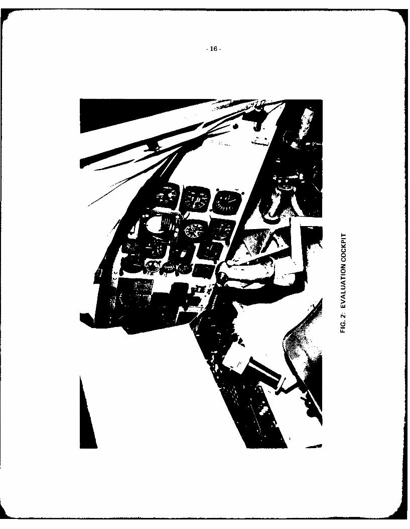
The layout of the evaluation pilot's cockpit for the instrument flying qualities experimentsis shown in Figure 2, where the conventional helicopter cyclic stick, collective lever and anti-torquepedal arrangement can be seen. Selection and control functions for the guidance, navigation andcommunication systems were accessible for left hand operation. The guidance and navigation aidswhich were available to the evaluation pilot for the instrument flight tasks included an ADF receiverwith bearing pointer displayed on a conventional Radio Magnetic Indicator (RMI), a VOR/ILS receiverwith localizer and glideslope information indicated on an Omni Bearing Selector (OBS), and a Micro-wave Landing System (MLS) receiver. The MLS provided localizer and variable-gradient glideslopeinformation which was displayed in the form of raw signals on the Main Attitude display of the flightdirector.
. , .. . . . . . . . .. . ... ... . . .. .ll l~l . .. . .. . .. . .. . i I II I . . . . .. . . . 1 +

-3-
3.0 MODELLING
The helicopter models were implemented using the response feedback technique wherebythe control response and apparent natural modes of the simulator are modified by a direct feedbackaugmentation of its inherent characteristics. Although this approach has shortcomings which can beavoided with the more elegant model-controlled or model-following method of simulation, there arecompensating factors which weighed heavily on the side of the simple response feedback for thisprogram: using this method the stability and control characteristics which were not of primary con-cern in the program and which were not explicitly "modelled" in the simulation software, exhibitedBell 205 behaviour. This meant, for example, that the models had all of the asymmetries, cross-coupling and non-linearities associated with conventional helicopter control systems - withoutnecessitating an elaborate modelling of the mechanisms which produce these effects. The background"Huey" characteristics also provided a relatively well known baseline against which the various eva-luated configurations could be judged.
The models were therefore conceptually very simple. Roll damping changes were accom-plished by varying the gain in a roll-rate-gyro to lateral-cyclic feedback path and roll attitudestabilization (wing-leveller) was implemented through a roll attitude feedback to the same control.Similar feedback paths were provided for yaw rate and lateral velocity to tail rotor collective; forpitch attitude, pitch attitude rate and forward speed to longitudinal cyclic; and for the rate of changeof forward speed (ti) to the electric elevator.
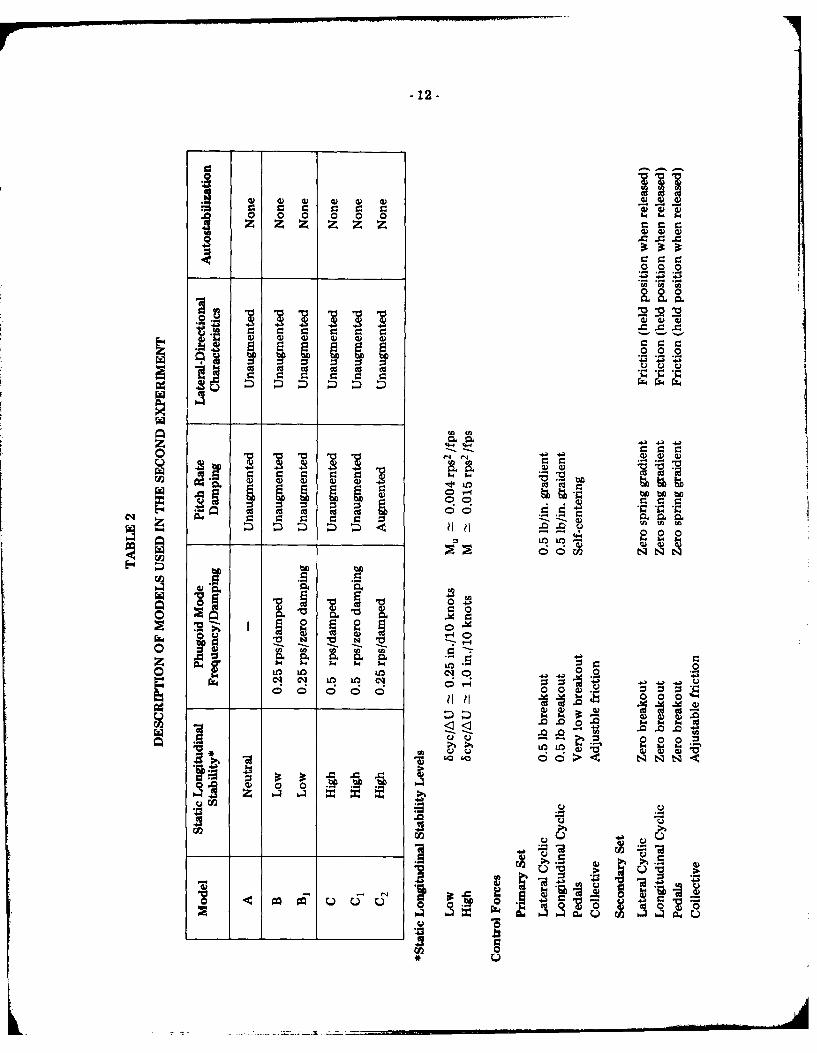
The qualitative effects of most of these augmentation paths are well understood and requireno elaboration. All of the models used in the first experiment, for example, required only rate andattitude feedback in the rotary degrees of freedom and the general characteristics of these simulatedhelicopters are summarized in Table 1. However, since the interactions among three of the feedbackpaths were of particular importance in the design of the models for the final two experiments, theeffects of variations in gain in these paths on the static and dynamic longitudinal stability of the heli-copter are illustrated in Figures 3 and 4. It can be seen that an increase in the speed stability derivative,MU, tends to increase the phugoid mode frequency and reduce long period damping - at the sametime as it increases the static longitudinal (stick position) stability. The ML -augmentation, on the otherhand, controls phugoid damping without significantly affecting phugoid frequency or static stability.(These effects and the insensitivity of the short-period characteristics to both M u and M u augmentationcan be seen in Figure 3.) The models used in the second experiment were based on the combinedeffects of augmentation to the speed stability derivatives and u-damping. Table 2 presents a brief des-cription of these models.
In the third and final experiment the pitch damping derivative M; was used in conjunctionwith M u and M to vary the static stability while keeping both the frequency and damping of thephugoid mode sensibly constant (Fig. 4). Since the static stability is affected by the value of M u, butis independent of both Mu and M;, this isolation of static longitudinal stability from phugoid charac-teristics is possible. The variations in M; do nevertheless have an effect on the short period mode andthis fact must be considered when interpreting the pilot assessments for the third test phase.
Finally, an artificial turbulence model was available to increase pilot workload and to pro-duce a more representative operational environment. The "canned" turbulence was not used at all inthe preliminary experiment; in the second series of tests, models were evaluated both in the presenceof turbulence and in relatively stable conditions without the artificial disturbances. In the final ex-periment the turbulence was phased in gradually between 1700 and 1500 feet above ground, producinga moderate level of disturbance during the final stages of the approach and during the missed approachprocedure.
4.0 EXPERIMENTAL PROCEDURES
From a pilot workload standpoint the essential differences between single-pilot and two-pilot IFR operations are related to the management of non-control auxiliary tasks and to pilot fatigue
-4-
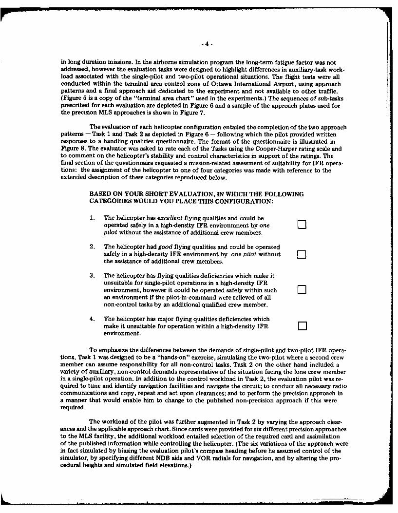
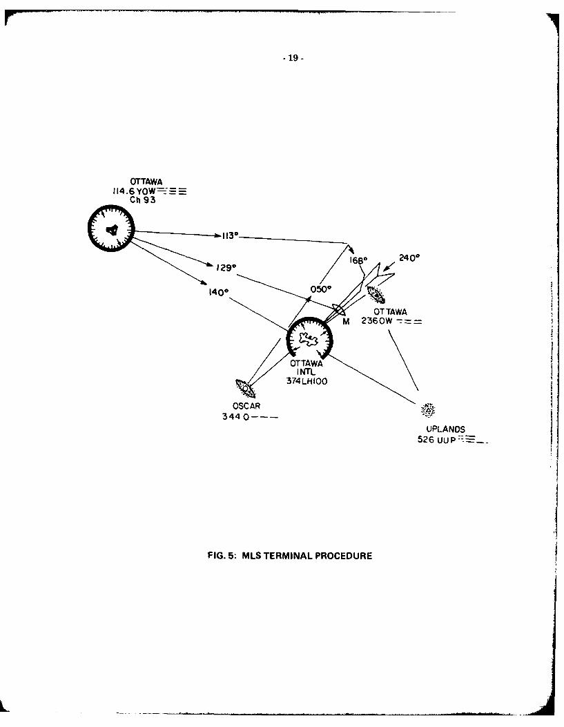
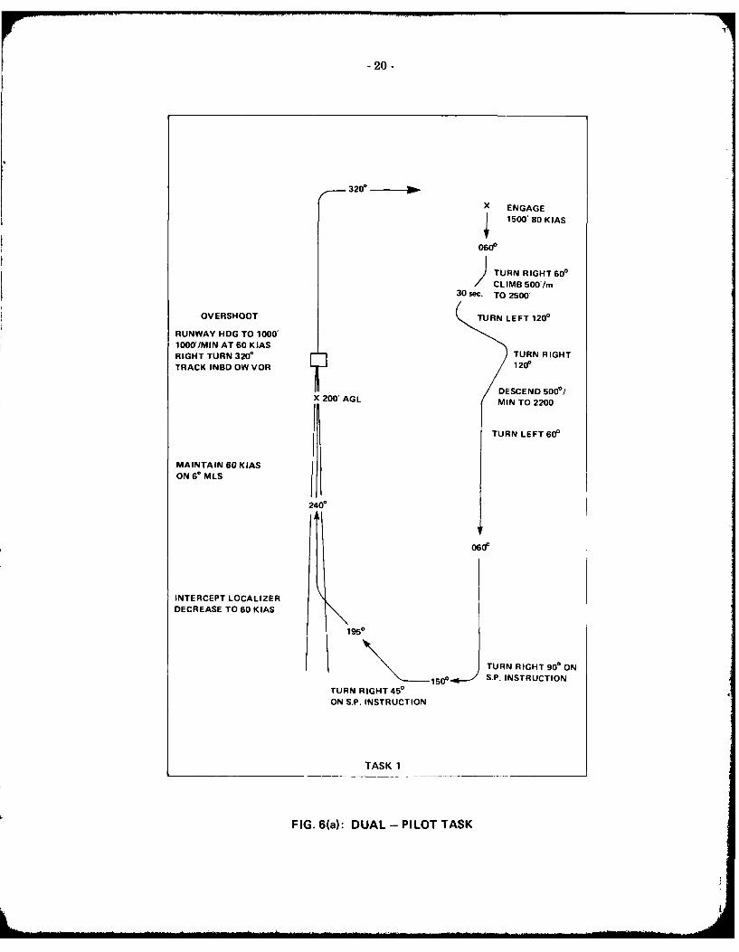
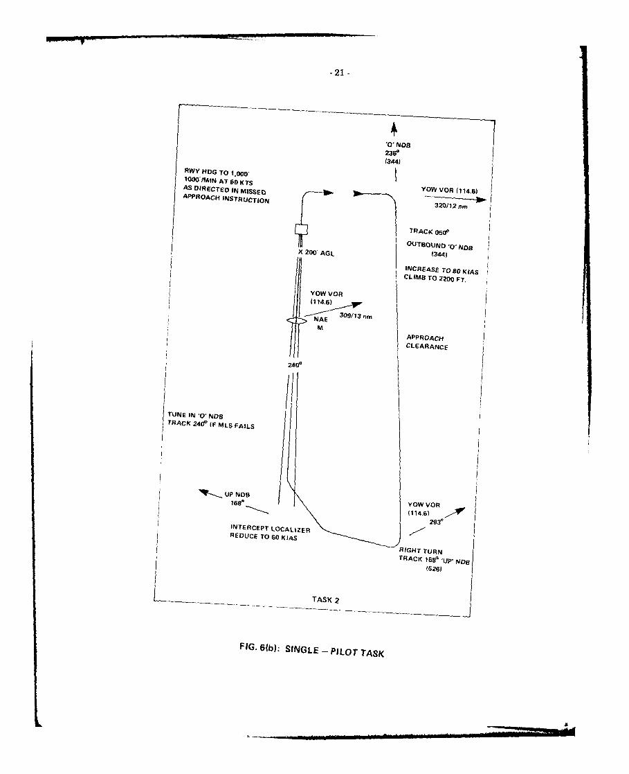
in long duration missions. In the airborne simulation program the long-term fatigue factor was notaddressed, however the evaluation tasks were designed to highlight differences in auxiliary-task work-load associated with the single-pilot and two-pilot operational situations. The flight tests were allconducted within the terminal area control zone of Ottawa International Airport, using approachpatterns and a final approach aid dedicated to the experiment and not available to other traffic.(Figure 5 is a copy of the "terminal area chart" used in the experiments.) The sequences of sub-tasksprescribed for each evaluation are depicted in Figure 6 and a sample of the approach plates used forthe precision MLS approaches is shown in Figure 7.
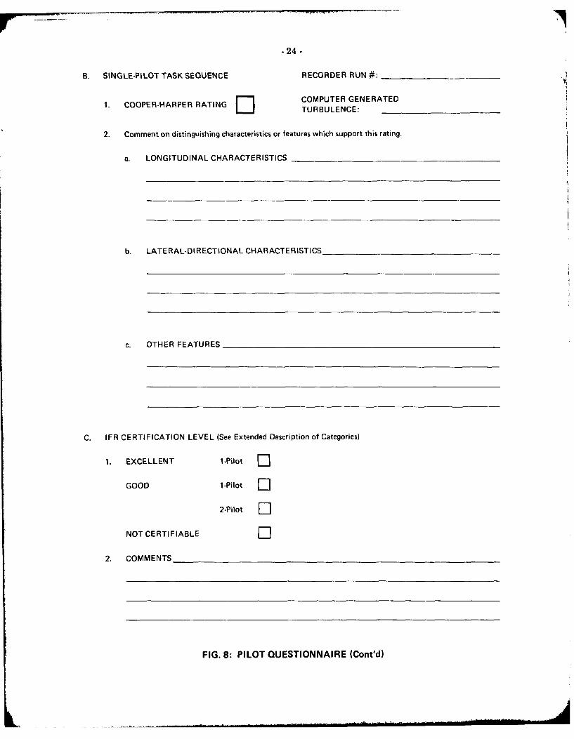
The evaluation of each helicopter configuration entailed the completion of the two approachpatterns - Task 1 and Task 2 as depicted in Figure 6 - following which the pilot provided writtenresponses to a handling qualities questionnaire. The format of the questionnaire is illustrated inFigure 8. The evaluator was asked to rate each of the Tasks using the Cooper-Harper rating scale andto comment on the helicopter's stability and control characteristics in support of the ratings. Thefinal section of the questionnaire requested a mission-related assessment of suitability for IFR opera-tions: the assignment of the helicopter to one of four categories was made with reference to theextended description of these categories reproduced below.
BASED ON YOUR SHORT EVALUATION, IN WHICH THE FOLLOWINGCATEGORIES WOULD YOU PLACE THIS CONFIGURATION:
1. The helicopter has excellent flying qualities and could beoperated safely in a high-density IFR environmnent by one lpilot without the assistance of additional crew members.
2. The helicopter had good flying qualities and could be operatedsafely in a high-density IFR environment by one pilot without -the assistance of additional crew members.
3. The helicopter has flying qualities deficiencies which make itunsuitable for single-pilot operations in a high-density IFRenvironment, however it could be operated safely within such Lan environment if the pilot-in-command were relieved of allnon-control tasks by an additional qualified crew member.
4. The helicopter has major flying qualities deficiencies whichmake it unsuitable for operation within a high-density IFR Lenvironment.
To emphasize the differences between the demands of single-pilot and two-pilot IFR opera-tions, Task 1 was designed to be a "hands-on" exercise, simulating the two-pilot where a second crewmember can assume responsibility for all non-control tasks. Task 2 on the other hand included avariety of auxiliary, non-control demands representative of the situation facing the lone crew memberin a single-pilot operation. In addition to the control workload in Task 2, the evaluation pilot was re-quired to tune and identify navigation facilities and navigate the circuit; to conduct all necessary radiocommunications and copy, repeat and act upon clearances; and to perform the precision approach ina manner that would enable him to change to the published non-precision approach if this wererequired.
The workload of the pilot was further augmented in Task 2 by varying the approach clear-ances and the applicable approach chart. Since cards were provided for six different precision approachesto the MLS facility, the additional workload entailed selection of the required card and assimilationof the published information while controlling the helicopter. (The six variations of the approach werein fact simulated by biasing the evaluation pilot's compass heading before he assumed control of thesimulator, by specifying different NDB aids and VOR radials for navigation, and by altering the pro-cedural heights and simulated field elevations.)

.5-
The instrument flight procedural tasks formed the basis for the handling qualities evaluationsof all three experiments. In the final experiment only, this operational evaluation was preceded by apreliminary series of tests wherein the pilots investigated the stability and control characteristics ofeach model using conventional flight test techniques. The model and the programmed values of itsstability and control characteristics were identified for the pilot before he performed this systematicassessment in accordance with the test card shown in Figure 9.
5.0 THE FLIGHT EXPERIMENTS
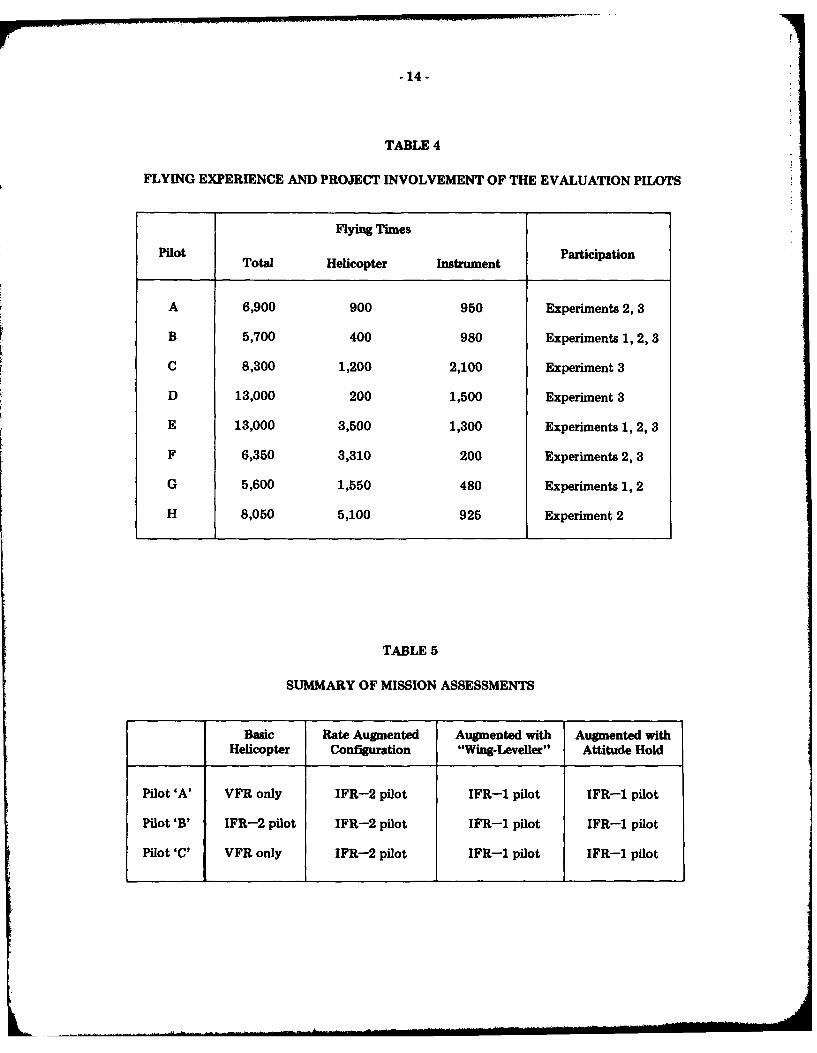
Eight test pilots representing the U.S. Federal Aviation Administration (3), the NationalAeronautics and Space Administration (1), Transport Canada (1), and the National AeronauticalEstablishment (3) participated in the evaluation flight testing. All are qualified helicopter test pilots,some with extensive IFR experience, although in most cases this IFR experience has been acquiredexclusively on fixed-wing aircraft. Three of the pilots are airworthiness test pilots who have performedinstrument flight certification programs for helicopters. Table 4 gives a general summary of the flyingexperience of the evaluators and lists the phases of the program in which each participated.
In total the pilots flew over 150 hours in simulated IFR terminal area operations. The threeexperiments are described and their results discussed below. The first two tests are treated briefly sincethey were essentially preparatory experiments for the third which is presented in detail.
5.1 The First Experiment
Much of the effort in this preliminary experiment was directed toward the design of suitableinstrument flight tasks for assessing the relative "certifiabiity" of various helicopter models for IFRflight. The evaluations of the models selected for these tests are of interest, nevertheless, since theyillustrate the improvements in instrument-flight handling qualities which can be achieved through theapplication of simple stability augmentation and autostabiization techniques. These techniques formthe basis of simple, safe and inexpensive systems for improving the inherent flying characteristics of ahelicopter.
Four simple models were evaluated in this series of tests, each having the simulator's inherentstatic stability characteristics. The four were:
a. the unaugmented Bell 205
b. the Bell 205 with rate augmentation in roll, pitch and yaw (SAS authority, ±10%)
c. the Bell 205 with rate augmentation in roll, pitch and yaw - and a selectable "wing levelling"attitude stabilizer (total authority of SAS and autostabiizer, ±10%, and
d. the Bell 205 with rate augmentation in roll, pitch and yaw - and a selectable "attitude hold"stabilizer in roll and pitch (total authority of SAS and autostabilizer, ±10%).
This experiment has been described in detail in Reference 4, however results of the evalua-tions are restated here to provide a context for the presentation of subsequent phases of the program.Table 1 summarizes the mission assessments of the four evaluated models.
For all instrument flight operations the pilots preferred configurations which possessed agreater degree of dynamic stability than that exhibited by the unaugmented helicopter. For two-pilotoperations, simple rate damping in roll, pitch and yaw was enough to bring the overall IFR workloadwithin reasonable limits and the handling qualities of the rate-augmented helicopter were consideredsuitable for two-pilot Category I IFR operations.

-6-
For single-pilot IFR flight, however, the pilots demanded a usable level of overall staticstability - usable in the sense that the helicopter could be left unattended for periods of time requiredfor non-control "housekeeping" tasks without risking large divergences from the original trimmedstate. In this experiment the static stability levels were unchanged from the inherent values of thesimulator (see Table 1) but improvements in trim retention were provided in the form of the selectableattitude stabilization modes described above. Although these systems were primitive both in designand implementation they provided a degree of relief from the control task workload, and confidencethat the helicopter would not diverge if left unattended, enabling a lone-pilot to fly the helicopter andmanage avionics systems, navigation taks and ATC interactions. The rate-augmented helicopter witheither the single-axis "wing-leveller" or with roll and pitch attitude hold was considered suitable forsingle-pilot IFR operations in a high traffic-density environment.
5.2 The Second Experiment
In this experiment, as in the subsequent one, the variables of primary interest were longitu-dinal static and dynamic stability. The main features of the models which were established for thissecond experiment are listed in Table 2. Static longitudinal stability was varied from strongly positiveto neutral through augmentation of the speed stability derivative M,,, while d-damping was used tocontrol the damping ratio of the resulting phugoid modes. In the primary series of models, A, B, C,the phugoid modes of the latter two were well damped while Model A, which had neutral speed stability,did not exhibit a low frequency oscillatory mode. When the neutrally stable Model A was disturbedfrom a trimmed state it tended to diverge slowly in speed (positively or negatively) while pitch attituderemained bounded and essentially constant.
The three models designed B, , C1 , and C2 were developed from B and C: Models B, and C1were identical to B and C respectively with the exception that the phugoid mode damping of B, andC1 was reduced to zero by eliminating the ii-darnping. Model C2 was another variant of C, the stronglyspeed-stable model, with the pitch rate damping increased to produce a lower frequency phugoid modeand improved short period characteristics while retaining the same high level of static stability.
Each of the models was flown with a control-force-feel system which provided positivebreakout and positive force gradients in roll, pitch and yaw, and in a separate series of tests, withfriction-only control forces. The models which possessed positive speed stability exhibited positivestick position stability in the absence of force gradients and positive stick force stability when gra-dients were present. (Control force levels are listed in Table 2.)
The results from the evaluation pilots' subjective assessment of the six models are presentedbriefly in the following paragraphs.
Longitudinal Stick Position Stability
Static longitudinal stick position stability without an accompanying stick force gradientdoes not appear to provide the pilot with usable information in a high-workload IFR en-vironment. Force gradients were considered desirable, even in the case of neutral speedstability, to avoid the introduction of inadvertent and undetected pilot control inputs.Light stick gradients with well-defined breakout forces were considered essential for single-pilot IFR flight and desirable for two-pilot IFR operations.
Longitudinal Stick Force Stability
The pilot ratings and the responses to the questionnaire indicated a clear preference forpositive stick force stability accompanied by "good" dynamic characteristics. Model C,with its strong speed stability, good short-period behavior and damped phugoid mode ofmoderate frequency (Tp - 25 seconds) was generally considered to be a good single-pilotIFR helicopter. The other two models which had this same high level of stick force stability -Models C and CI - were, however, consistently rejected for single-pilot IFR flight in turbu-lence, primarily because the speed stability was accompanied by a relatively high-frequencyphugoid mode. (This undesirable dynamic behavior is discussed below.)
-7-
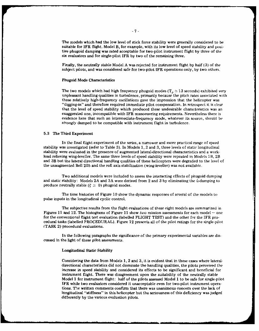
The models which had the low level of stick force stability were generally considered to besuitable for IFR flight. Model B, for example, with its low level of speed stability and posi-tive phugoid damping was rated acceptable for two-pilot instrument flight by three of thesix evaluators and for single-pilot IFR by two of the remaining three.
Finally, the neutrally stable Model A was rejected for instrument flight by half (3) of thesubject pilots, and was considered safe for two-pilot IFR operations only, by two others.
Phugoid Mode Characteristics
The two models which had high frequency phugoid modes (T. ± 13 seconds) exhibited veryunpleasant handling qualities in turbulence, primarily because the pitch rates associated withthese relatively high-frequency oscillations gave the impression that the helicopter was"digging-in" and therefore required immediate pilot compensation. In retrospect it is clearthat the level of speed stability which produced these undesirable characteristics was anexaggerated one, incompatible with IFR manoeuvring requirements. Nevertheless there isevidence here that such an intermediate-frequency mode, whatever its source, should bestrongly damped to be compatible with instrument flight in turbulence.
5.3 The Third Experiment
In the final flight experiment of the series, a narrower and more practical range of speedstability was investigated (refer to Table 3). In Models 1, 2 and 3, three levels of static longitudinalstability were evaluated in the presence of augmented lateral-directional characteristics and a work-load relieving wing-leveller. The same three levels of speed stability were repeated in Models 1B, 2Band 3B but the lateral directional handling qualities of these helicopters were degraded to the level ofthe unaugmented Bell 205 and the roll axis stabilization (wing-leveller) was not available.
Two additional models were included to assess the interacting effects of phugoid dampingand static stability: Models 2A and 3A were derived from 2 and 3 by eliminating the i-damping toproduce neutrally stable ( 0) phugoid modes.
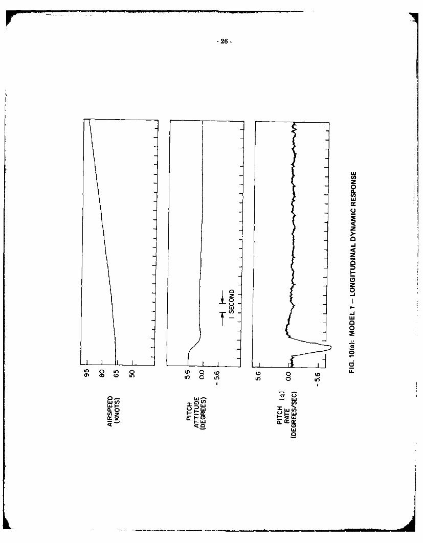
The time histories of Figure 10 show the dynamic responses of several of the models topulse inputs in the longitudinal cyclic control.
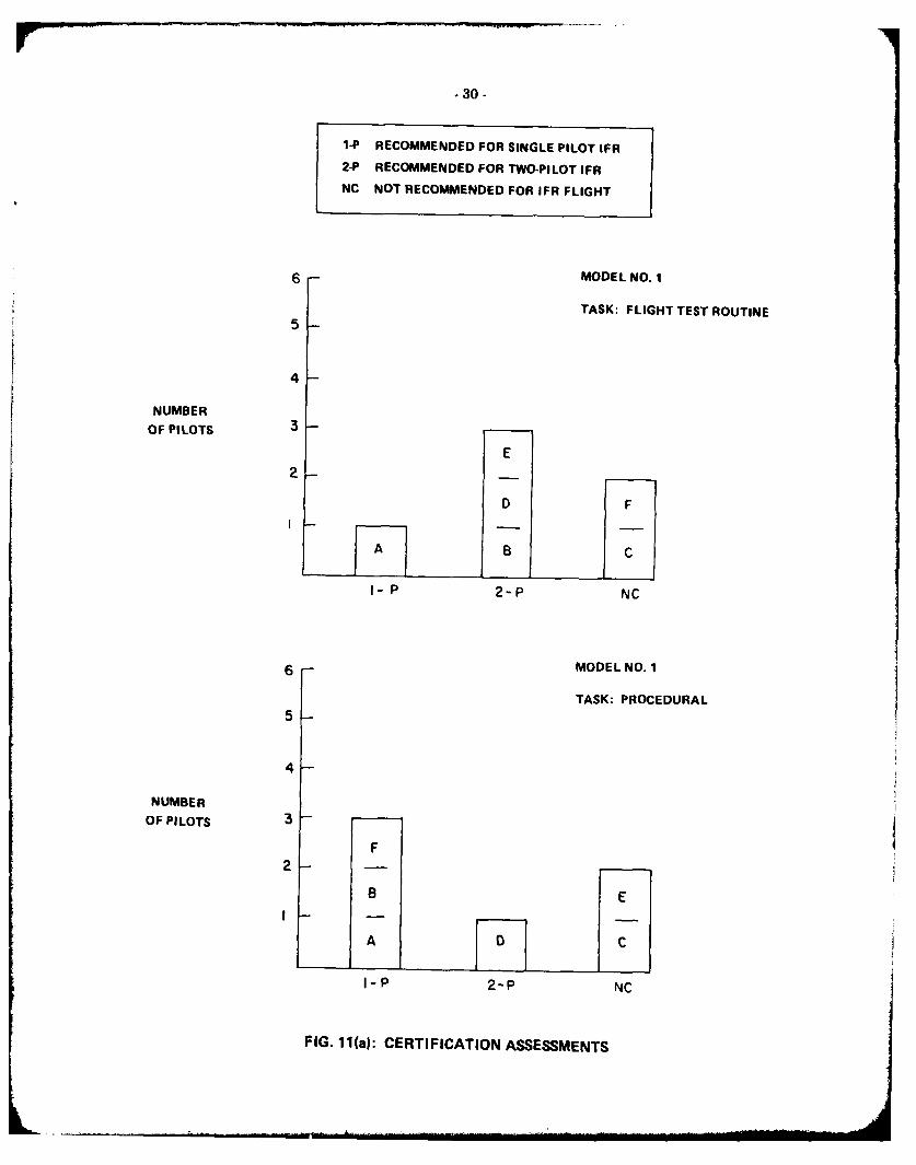
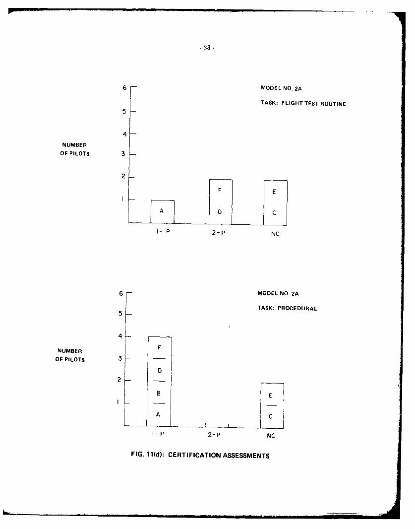
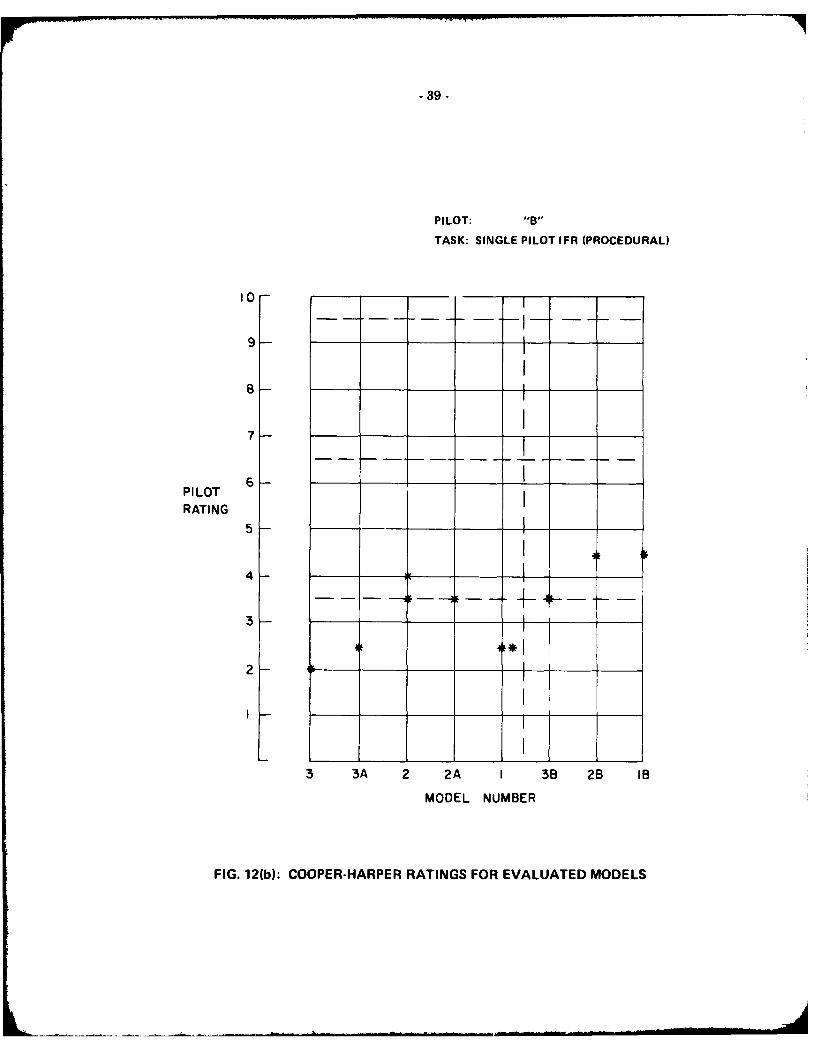
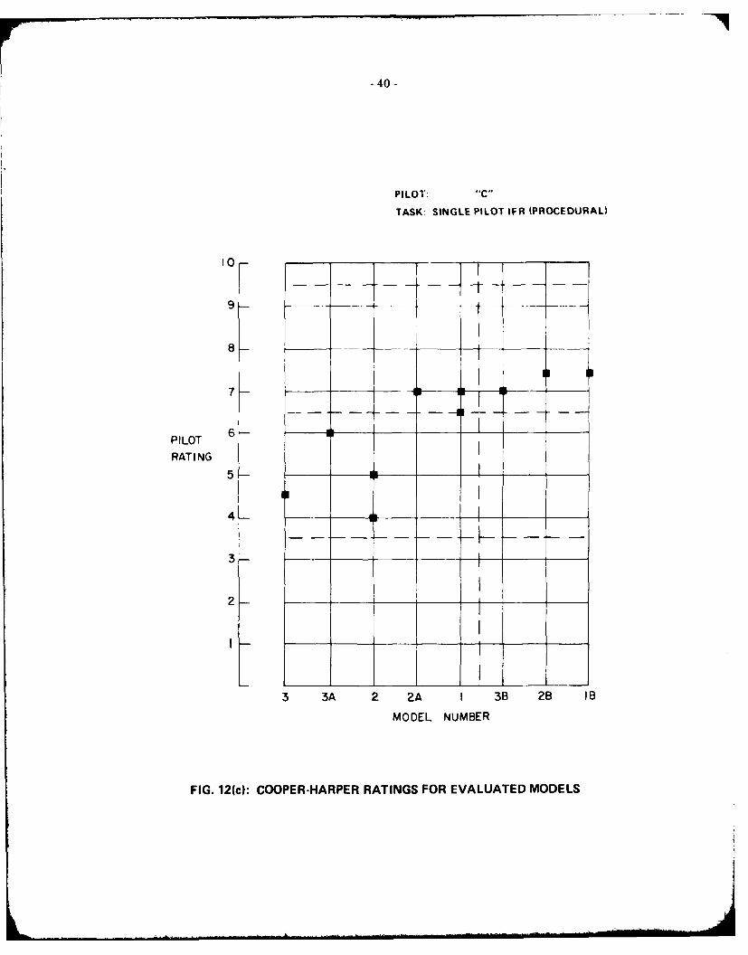
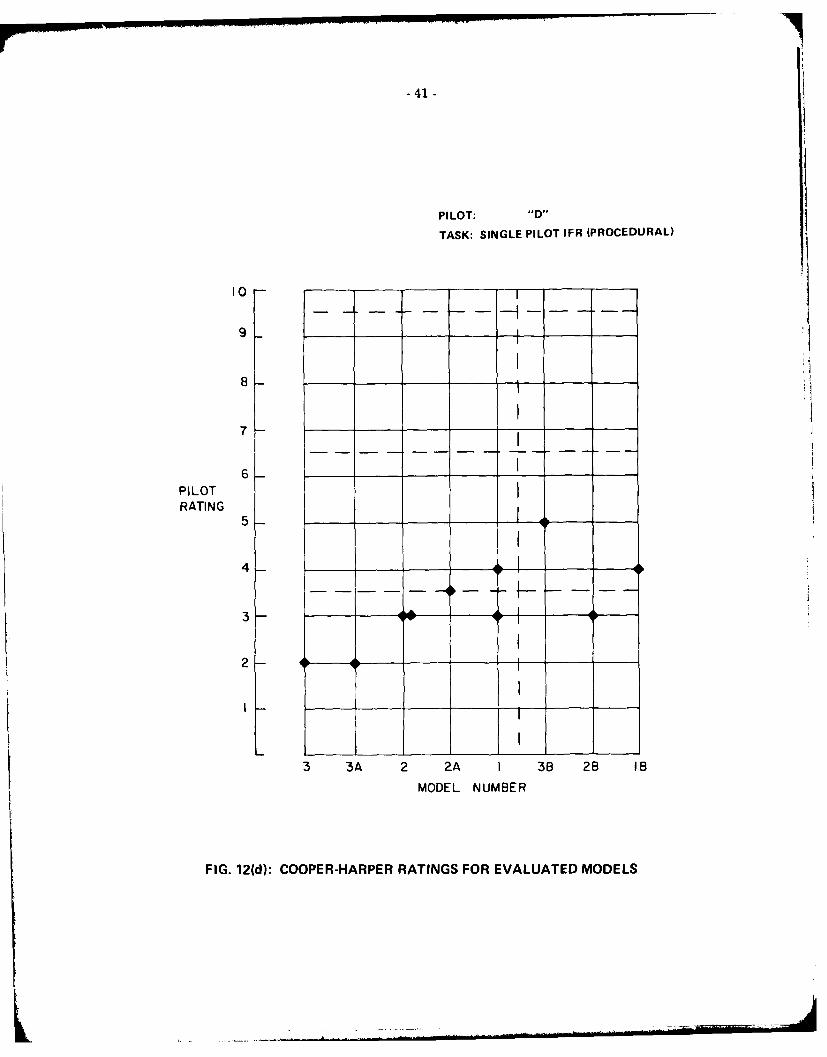
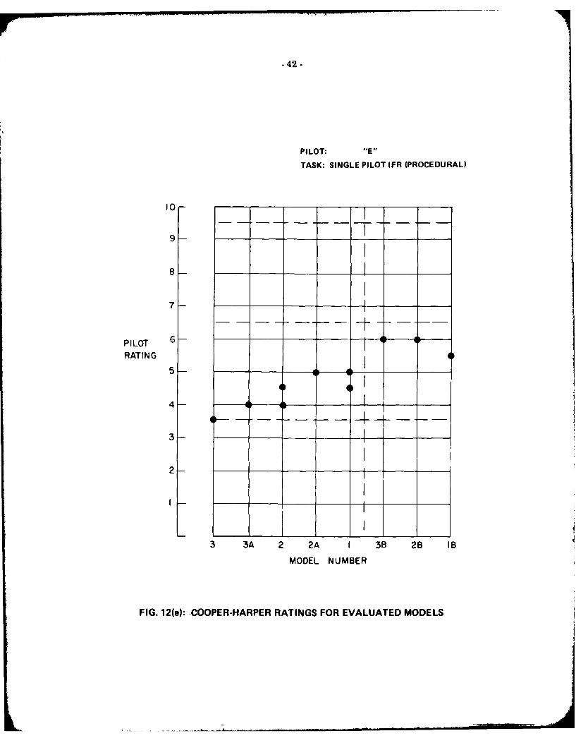
The subjective results from the flight evaluations of these eight models are summarized inFigures 11 and 12. The histograms of Figure 11 show two mission assessments for each model - onefor the conventional flight test evaluation (labelled FLIGHT TEST) and the other for the IFR pro-cedural tasks (labelled PROCEDURAL). Figure 12 presents all of the pilot ratings for the single-pilot(TASK 2) procedural evaluations.
In the following paragraphs the significance of the primary experimental variables are dis-cussed in the light of these pilot assessments.
Longitudinal Static Stability
Considering the data from Models 1, 2 and 3, it is evident that in these cases where lateral-directional characteristics did not dominate the handling qualities, the pilots perceived theincrease in speed stability and considered its effects to be significant and beneficial forinstrument flight. There was disagreement upon the suitability of the neutrally stableModel 1 for instrument flight: half of the pilots assessed Model 1 to be safe for single-pilotIFR while two evaluators considered it unacceptable even for two-pilot instrument opera-tions. The written comments confirm that there was unanimous concern over the lack oflongitudinal "stiffness" in this helicopter but the seriousness of this deficiency was judgeddifferently by the various evaluation pilots.

-8-
Model 2, on the other hand, with a low positive level of static longitudinal (speed) stabilitywas considered satisfactory for single-pilot IFR by half of the pilots and was rated suitablefor two-pilot operations by the remaining half of the group. Here the annoyance of collective-to-pitch cross-coupling and an uncomfortable pitch sensitivity to gusts were cited as prob-lems. Both of these complaints may be attributed to the lower level of pitch rate dampingpresent in Model 2. In order to maintain the same phugoid frequency for all of the modelsin this group which exhibited phugoid oscillations, it was necessary to reduce the pitchdamping of Models 2, 2A and 2B to the simulator's inherent level. (It should be noted thatin the first of these experiments a helicopter very similar to Model 2 was assessed to beacceptable for single-pilot IFR. That aircraft, with similar static longitudinal stability andlateral-directional characteristics to Model 2, had significantly greater pitch rate damping(AMq - - P.)
The situation is much clearer in the case of Model 3: with the moderate level of speedstability, good pitch damping and the augmented lateral-directional characteristics, thishelicopter was considered satisfactory for single-pilot IFR operations by five of the sixevaluation pilots. The one dissenting view was a "borderline single-pilot" assessment baseuon the undesirable level of collective-to-pitch cross-coupling. All of the pilots consideredthe level of speed-stability of this model to be agreeable.
Interactions Between Lateral-Directional and Longitudinal Characteristics
When the lateral-directional characteristics of the modelled helicopters were degraded, theworkload associated with lateral-directional stabilization and control dominated the handlingqualities assessments. Models 1B, 2B and 3B received mixed ratings which do not appear tobe correlated with the static stability levels. The pilot ratings were as much as 2.5 pointshigher than those for the corresponding models with good lateral-directional characteristics,and the mission assessments categorized these helicopters as unacceptable for IFR flight orsuitable for two-pilot IFR only.
Phugoid Damping
A decrease in the phugoid dampoing of Models 2 and 3, as implemented in 2A and 3A, hadlittle influence on the pilot ratings but a decided effect on the mission assessments. (Figures11(d), 11(e) and Figure 12). The comments of several of the pilots indicated that the onsetof the slow periodic motion of these undamped phugoid modes was mistakenly interpretedas a lack of speed stability and the ratings were downgraded on this basis. There was supportfor both of these models as single-pilot IFR helicopters: in the procedural evaluations fourof the pilots suggested that 2A was safe for single-pilot IFR. The dissenting views werenevertheless stronger in these cases than in the evaluations of the damped-phugoid versionsof the same helicopters.
Cross-Coupling
The control cross-coupling of collective into the pitch, roll and yaw axes was cited by anumber of pilots as a major contributor to workload during the missed approach procedure.(The level of control cross-coupling exhibited by the models in these experiments was thatof the Bell 205.) During a typical transition to missed approach, prior to retrimming, thepilot was required to provide approximately 15% of total nose down cyclic authority, 15%left pedal, and 8% left cyclic to maintain aircraft attitude and speed. These effects were alsoevident during approach tracking when collective-to-pitch coupling tended to contaminatethe speed stability of the aircraft. The dominance of this undesirable coupling in some casesobscured the assessment of the primary parameter variations in the experiments.

-9-
6.0 CONCLUDING REMARKS
The form and content of the static longitudinal stability requirements contained in theInterim Standards for Helicopter IFR Certification were the basis for the initial design of the experi-ments described in this report. It was nevertheless inevitable that the subject matter of the programshould be broadened to address the interacting effects of static and dynamic stability, and the impor-tance of good lateral-directional characteristics on the overall handling qualities of a helicopter. Theresults from these experiments suggest that the following stability and control characteristics areimportant considerations in the development of helicopter instrument flight handling qualities re-quirements:
a. good rate damping in the rotary degrees of freedom (damping levels between -1.0 and-2.0 sec- I were used in the rate augmented systems evaluated in this program),
b. no rapid spiral mode departures. (Requirements for spiral mode time constants were notdirectly addressed in the experiments but many of the models eliminated this mode usingthe simple wing-leveller. Experiments specifically addressing the effect of lateral and longi-tudinal aperiodic departures on instrument flight handling qualities are presently beingcarried out at the NAE.),
c. minimal levels of control coupling and dynamic cross-coupling, and
d. good positive speed stability along with light, positive breakout and gradient forces for theroll and pitch cyclic controls. (Speed stability derivative values in the range from 0.004and 0.007 (rad/sec 2 )/(ft/sec) were considered satisfactory for instrument flight.)
All four of these conditions should be met to ensure good single-pilot instrument flight handlingqualities; however, in the absence of any one of the four, an equivalent level of safety can most easilybe provided by some form of attitude stabilization.
Finally, the minimum required levels of handling qualities for two-pilot IFR operations aremore difficult to define since the helicopter pilot's traditional tolerance for "bad" flying qualitiesappears to carry over to the IFR environment if he is able to concentrate on the control tasks. Ifadopted, the provisions of the Notice of Proposed Rulemaking (Ref. 4) would continue the practiceof establishing less stringent stability and control requirements for instrument-flight certification ofhelicopters when the minimum crew complement is two instrument-qualified pilots. As helicoptercontrol systems evolve and the instrument flight mission plays a more important part in the designprocess of future helicopters, the need for these two-tiered handling qualities requirements shoulddiminish. Then for helicopters, as for fixed-wing aircraft, there should be no relaxation of IFR sts-bility and control requirements based on workload relief provided by additional crew.
7.0 ACKNOWLEDGEMENT
The names and affiliations of the participating test pilots are listed below:
P. Balfe FAAR.M. Gerdes NASAS.W. Grossmith Transport CanadaS. Kereliuk NAEJ.M. Morgan NAEJ.C. Watts FAAH. White FAAA.D. Wood NAE
8.0 REFERENCES
1. Welsh, G.W. Instrument Flight Requirements for Bell Model 212 Helicopter.Letter SW-216, Federal Aviation Administration, SouthwestRegion, July 1970.
-10-
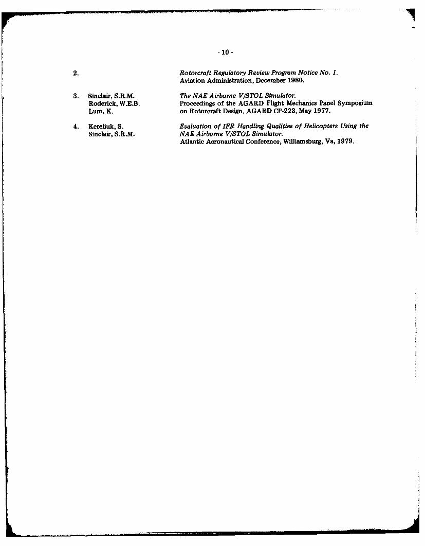
2. Rotorcraft Regulatory Review Program Notice No. 1.Aviation Administration, December 1980.
3. Sinclair, S.R.M. The NAE Airborne V/STOL Simulator.Roderick, W.E.B. Proceedings of the AGARD Flight Mechanics Panel SymposiumLum, K. on Rotorcraft Design. AGARD CP-223, May 1977.
4. Kereliuk, S. Evaluation of IFR Handling Qualities of Helicopters Using theSinclair, S.R.M. NAE Airborne VISTOL Simulator.
Atlantic Aeronautical Conference, Williamsburg, Va, 1979.

.00
S 0 0 0
z z
.
0 .4a
:a 3-, 0
0
0
i 0 00
U) 0.
00 0
~ , 40
434D4
93 ~ ..
~- -
0 0 0 0 0 0 - Lzzz z z z
4: 00
0.00
0 C * d Cd
Li Li00
04*
wci00
0000
.61
4azo 3-9 5-41
3 ~ 0 Ow o U

-s ~ ~ w s- 0A- -0 ~*
z
CUd
z w W
0 0
00
d q 4)I N ) C 4 ) N m ~ -IZ .V .
- 14 -
TABLE 4
FLYING EXPERIENCE AND PROJECT INVOLVEMENT OF THE EVALUATION PILOTS
Flying Times
Total Helicopter Instrument Participation
A 6,900 900 950 Experiments 2, 3
B 5,700 400 980 Experiments 1, 2, 3
C 8,300 1,200 2,100 Experiment 3
D 13,000 200 1,500 Experiment 3
E 13,000 3,500 1,300 Experiments 1, 2, 3
F 6,350 3,310 200 Experiments 2, 3
G 5,600 1,550 480 Experiments 1, 2
H 8,050 5,100 925 Experiment 2
TABLE 5
SUMMARY OF MISSION ASSESSMENTS
Basic Rate Augmented Augmented with Augmented withHelicopter Configuration "Wing-Leveller" Attitude Hold
Pilot 'A' VFR only IFR-2 pilot IFR-1 pilot IFR-1 pilot
Pilot 'B' IFR-2 pilot IFR-2 pilot IFR-1 pilot IFR-1 pilot
Pilot 'C' VFR only IFR-2 pilot IFR-1 pilot IFR-1 pilot

.
- 16 -
I-
-I
N
U-

17-
U,
0U,
S
z0. 2
I-4I-
__ __ zLU
4
024
C,_______ 2
z
oU
___ ___ ___ ___ ILo 0- - (4
I.-C.)LUU-U-LU
U
o ILU
=~
____ 4- 4iZ~ z~~sLU
LU r fl!~b0. ul ~
Ao Az ___ ____ ____ I
'4t-. _ i __
0

18 --
z
0
IC -
0
U,
- - IA.
c00nUcr I-
- 19 -
OTTAWA114.6 YOW-==
M 236OW-
I NT.
3440---UPLANDS
526 UUP::--
FIG. 5: MLS TERMINAL PROCEDURE
- 20 -
S320*YX ENGAGE$ 1500' 80 KIAS
060
) TURN RIGHT 600
CLIMB 500'/m30 sOc. TO 2500'
OVERSHOOT TURN LEFT 1200
RUNWAY HDG TO 1000'1000/MIN AT 60 KIASRIGHT TURN 3200 TURN RIGHTTRACK INBD OW VOR 1200
DESCEND 5000/X200'AGL MIN TO 2200
TURN LEFT 600
MAINTAIN 60 KIASON 6* MLS
240
INTERCEPT LOCALIZER
DECREASE TO 60 KIAS
.1950TURN RIGHT 900 ON
1500 . S.P. INSTRUCTIONTURN RIGHT 450ON S.P. INSTRUCTION
TASK 1
FIG. 6(a): DUAL - PILOT TASK
24?(344)
RWY HOG TO 1,000,1000'/MIN AT 60 IKTS
AS DIRECTED flN MISSED O O (1,3APPROACH INSTRUCTION 32OW 1 VO(146
TRACK 050"
OUTBOUND -0' NOSX 200' AGI 34
INCREASE TOBO0KIAS
CLIMB TO 2200 FT.
Y OW VOR
J NAE 013nM APPROACH
CLEARANCE
TRC 4'I L FAILS
UP NOS
o G1 6 8 ~ ( 1 1 4 .6 )
INTERCEPT LOCALIZER 23REDUCE TO 60 KIAS E
RIGHT TURNTRACK 168P 'UP' NOBo
(526)
TASK 2
FIG. 6(b): SINGLE - PILOT TASK

- 22.
MIS/NOB RWY 24 NAE
NAE APP ELEV 400
129.6
OTTAWA114.6 vow
12SP/13 n A
( OTTAWA
OW26 _
MISSED APPROACH NE 0
RIGHT TURN 0600M 20TRACK INDS OW NOBMAINTAIN 2200 ft. 1650
1000
FULL MLS 600 (200) Y RVR 26
G/P INOP 8001400) 1 RVR 50
AOF STR. IN 900(150011 R VR 50
NAE M TO RWY 2.0 nm
KNOTS j40 60 80
MIN:SEC 2:55 1:58 1:28
FIG. 7: SAMPLE MLS APPROACH PLATE

- 23 -
EVALUATION PILOT: ___________FLIGHT #:___________
CONFIGURATION #: _ ________DATE: _________
WEATHER AND WINDS: _____________________________
A. TWO-PI LOT TASK SEQUENCE RECORDER RUN#:__________
1. COOPER-HARPER RATING COMPTURRULENERATED _______
2. Comment on distinguishing characteristics or features which support this rating:
a. LONGITUDINAL CHARACTERISTICS____________________
b. LATE RA L-DI RECTIONAL CHARACTERISTICS_________________
C. OTHER FEATURES _______________________________
FIG. 8: PILOT QUESTIONNAIRE
-24 -
B. SINGLE-PILOT TASK SEQUENCE RECORDER RUN#:
1COMPUTER GENERATED
1. COOPER-HARPER RATING UTURBULENCE:
2. Comment on distinguishing characteristics or features which support this rating.
a. LONGITUDINAL CHARACTERISTICS
b. LATERAL-DIRECTIONAL CHARACTERISTICS
c. OTHER FEATURES
C. IFR CERTIFICATION LEVEL (See Extended Description of Categories)
1. EXCELLENT 1-Pilot F-1
GOOD 1-Pilot r_]
2-Pilot E-
NOT CERTIFIABLE F]
2. COMMENTS
FIG. 8: PILOT QUESTIONNAIRE (Cont'd)

-25 -
DYNAMIC RESPONSE TRIMMED 70 KIASSTRAIGHT AND LEVEL
a. LATERAL CYCLIC PULSES (Ao < 100)LEFTRIGHT
b. LONGITUDINAL CYCLIC PULSES (60 < 50)NOSE UP
DOWN
c. PEDAL PULSES (t3 < 10)
LEFTRIGHT
d. COLLECTIVE STEPS (Abc < 1")UPDOWN
2. LONGITUDINAL STATIC STABILITY TRIMMED 70 KIASSTRAIGHT AND LEVEL
a. 70 KIAS - 80 -* 60 -- 70CONSTANT ALTITUDE, NO TRIMMING
b. 70 KIAS - 80 -- 60 -+ 70CONSTANT ALTITUDE, NO TRIMMING
3. TURNING MANOEUVRES TRIMMED 70 KIASSTRAIGHT AND LEVEL
20 DEGREE BANK TURN RIGHT 90'
REVERSE LEFT 900
4. STABILITY IN CLIMBS AND DESCENTS TRIMMED 70 KIASSTRAIGHT AND LEVEL
a. T 1000FPM, Ah = 500', RETRIM
b. 1000FPM, Ah = 500', RETRIM
FIG. 9: FLIGHT TEST ROUTINE
-26 -
LU
z
100
-J
w 0
w UI-
tfl 0 uLW c
IX x - 0 - W
- 27 -
z
CC,
0
-I
0
zz00
uLw0
xw
mo mo W
oiL
wI

- 28 -
LU
0C,,LU
LU
z 0.-- J
ui4(n c2
L-
w LU x0. cr0
z 0 W
'AW ot ww0 C

- 29 -
CL
0
LLu
W-Jw4X ato xz
UDW Izwo c0jr Z c-
- 30 -
1-P RECOMMENDED FOR SINGLE PILOT IFR2-P RECOMMENDED FOR TWO-PILOT IFRNC NOT RECOMMENDED FOR IFR FLIGHT
6 MODEL NO. 1
TASK: FLIGHT TEST ROUTINE
5
4
NUMBEROF PILOTS 3
E2
D F
A B C
I- P 2-P NC
6 MODEL NO. 1
TASK: PROCEDURAL5
4
NUMBEROF PILOTS 3
F
2 -B E
I -A 0
I-P 2-P NC
FIG. 11(a): CERTIFICATION ASSESSMENTS

- 31 -
6 MODEL NO. 2
TASK: FLIGHT TEST ROUTINE
5
4E
NUMBEROF PILOTS 3
D
2-
B F
A C
I-P 2-P NC
6 MODEL NO. 2
TASK: PROCEDURAL
5
4-
NUMBEROF PILOTS 3
F E
2-
0 C
A -
A B
I- P 2-P NC
FIG. 11(b): CERTIFICATION ASSESSMENTS

- 32 -
6 MODEL NO. 3
TASK: FLIGHT TEST ROUTINE
5
4
ENUMBER
OF PILOTS 3D
2 -B
I
A F C
I- P 2-P NC
MODEL NO. 3
TASK: PROCEDURAL
5
F
4 -
NUMBER D POSSIBLE 1-P
OF PILOTS 3 -
C
2
8
A
I- P 2-P NC
FIG. 11(c): CERTIFICATION ASSESSMENTS
- 33-
6 MODEL NO. 2A
TASK: FLIGHT TEST ROUTINE
5
4NUMBER
OF PILOTS
F E
A D C
I- P 2-P NC
6 MODEL NO. 2A
TASK: PROCEDURAL5
NUMBER F
4-
OF PILOTS 3
DI
2
B E
A C
I-P 2-P NC
FIG. 11(d): CERTIFICATION ASSESSMENTS

- 34-
6- MODEL NO. 3A
TASK: FLIGHT TEST ROUTINE
5
4
NUMBER
OF PILOTS 3
2
D F
A C E
I- P 2-P NC
6 MODEL NO. 3A
TASK: PROCEDURAL
5
4
NUMBER
OF PILOTS 3
D F
2 -
B E
A C
I- P 2-P NC
FIG. 11(e): CERTIFICATION ASSESSMENTS

-35-
6 MODEL NO. 1B
TASK: FLIGHT TEST ROUTINE
5
4
NUMBER F
OF PILOTS 3 --
E2 -
D
I -
I- P 2-P NC
6 MODEL NO. 1B
TASK: PROCEDURAL
5
4F
NUMBEROF PILOTS 3
D
2
B E
A C
S I_
I- P 2-P NC
FIG. 11(f): CERTIFICATION ASSESSMENTS

- 36 -
MODEL NO. 2B
6TASK: FLIGHT TEST ROUTINE
5
4
FNUMBER
OF PILOTS 3
E2
D
I- P 2-P NC
6- MODEL NO. 2B
TASK: PROCEDURAL
5
4
NUMBER
OF PILOTS 3
F2
B E
D A C
I-P 2-P NC
FIG. 11(g): CERTIFICATION ASSESSMENTS

-37 -
MODEL NO. 3B6
TASK: FLIGHT TEST ROUTINE
5 -
4
NUMBER
OF PILOTS 3
E
2
F
A C
I- p 2-P NC
MODEL NO. 3B
TASK: PROCEDURAL
4
FNUMBER
OF PILOTS
2
B E
A DI __ _
I-P 2-P 'NC
FIG. 11(h): CERTIFICATION ASSESSMENTS

1
- 38 -
PILOT: "A"
TASK: SINGLE PILOT IFR (PROCEDURAL)
10 -
9
8 _ _ _ _ _ _I CONTROLLABLE
7
PI LOT 6 TRATING
5 ACCEPTABLE
4I4 _____-
---- ,1----
2 -- SATISFACTORY
LII _ _ _
3 3A 2 2A I 3B 2B IB
MODEL NUMBER
FIG. 12(a): COOPER-HARPER RATINGS FOR EVALUATED MODELS
- 39 -
PILOT: "B"
TASK: SINGLE PILOT IFR (PROCEDURAL)
10-
9-
PI LOTRATING
i*12
3 3A 2 2A I 3B 28 1B
MODEL NUMBER
FIG. 12(b): COOPER-HARPER RATINGS FOR EVALUATED MODELS
-40 -
PILOT:
TASK. SINGLE PILOT IFR (PROCEDURAL)
I0-
7-
PILOT 6 __
RATING5
3-
3 3A 2 2A I 38 28 lB
MODEL NUMBER
FIG. 12(c): COOPER-HARPER RATINGS FOR EVALUATED MODELS
- 41 -
PILOT: "D"
TASK: SINGLE PILOT IFR (PROCEDURAL)
10
8__
7
6 _
PILOTRATING
5 _
4 _ -4--
4--F
2II
LI
3 3A 2 2A I 38 2B IB
MODEL NUMBER
FIG. 12(d): COOPER-HARPER RATINGS FOR EVALUATED MODELS
* 42 -
PILOT: E
TASK: SINGLE PILOT IFR (PROCEDURAL)
10-
9 -_ _ _ _ _
7--
PILOT 6RATING
-- 4-3-
2---
3 3A 2 2A 1 38 28 lB
MODEL NUMBER
FIG. 12(e): -COOPER-HARPER RATINGS FOR EVALUATED MODELS

- 43 -
PILOT: ""
TASK: SINGLE PILOT IFR (PROCEDURAL)
9-
8-
7-
PILOT 6-
RATING
5 -- ~
4-
3
3 3A 2 2A 1 38 28 Is
MODEL NUMBER
FIG. 12(f): COOPER-HARPER RATINGS FOR EVALUATED MODELS
EE
z z ~ -z -
17,7
2 '.2
E E-
Er E 2
-A ,

I,'D TE1Imml