national cooperative highway research program research ... · akashi-kaikyo bridge and the ohnaruto...
TRANSCRIPT

TRANSPORTATION RESEARCH BOARDNATIONAL RESEARCH COUNCIL
National Cooperative Highway Research Program
RESEARCH RESULTS DIGESTNovember 1998—Number 232
Subject Area: IIC Bridges, Other Structures, Responsible Senior Program Officer: Edward T. Harriganand Hydraulics and Hydrology
Report on the 1997 Scanning Review ofAsian Bridge Structures
This digest summarizes the the findings from NCHRP Project 20-36, “Highway Research and Technology—InternationalInformation Sharing,” conducted by a scanning review team of representatives from U.S. federal, state, and private sector
agencies. This digest was prepared by Henry G. Russell, Report Facilitator for the review.
SUMMARY
This digest describes the findings of an inter-national scanning tour undertaken to obtain a broadoverview of bridge design, materials technology,construction procedures, and maintenance prac-tices in Asia. The scanning team focused on iden-tifying technological developments in Asia thathave the potential for application in the UnitedStates. In addition, the team shared informationwith their international counterparts on U.S. prac-tices in highway bridge construction, maintenance,and management to promote international ex-change and cooperation.
The scanning tour concentrated on the follow-ing topics:
• Design standards, codes, and specifications;• Design and construction practices;• Materials, fabrication, and joining techniques;• Bridge protection strategies;• Inspection and rehabilitation practices;• Programming and management practices; and• Innovations.
The review was performed by an 11-memberteam representing several of the states, the FederalHighway Administration (FHWA), American As-
sociation of State Highway and TransportationOfficials (AASHTO), and National CooperativeHighway Research Program (NCHRP). The scan-ning tour took place from September 12 throughSeptember 28, 1997, and involved visits to Japan,South Korea, and Taiwan.
In Japan, the team met with representatives ofthe Honshu-Shikoku Bridge Authority (HSBA),Public Works Research Institute (PWRI), JapanHighway Public Corporation (JH), MetropolitanExpressway Public Corporation (MEPC), TokyoInstitute of Technology, Nippon Steel Corporation,and Yokogawa Bridge Corporation. In South Ko-rea, the team met with representatives of the KoreaHighway Corporation (KHC). In Taiwan, the teammet with representatives of the Taiwan AreaNational Freeway Bureau and the Taiwan AreaNational Expressway Engineering Bureau of theMinistry of Transportation and Communications.In all three countries, site visits were made to majorbridges.
On the basis of the observations made duringthe scanning review, the team developed a list of30 topics for possible application in the UnitedStates. The list was then divided into 6 high-prior-ity topics, 7 medium-priority topics, and 17 othertopics for consideration at a later date.

2
CONTENTS
Summary, 1High-Priority Topics, 3Medium-Priority Topics, 3Other Topics, 3
Introduction, 3Purpose, 3Sponsoring Organizations, 4Team Members, 4Metric Equivalents, 4Organizations and Site Visits, 4
Summary of Recommended Technologies, 13High-Priority Topics, 13Medium-Priority Topics, 14Other Topics, 15
Design Standards, Codes, and Specifications, 18Japan, 18South Korea, 18Taiwan, 19Recommendations on Design Standards, Codes, and Specifications, 19
Design and Construction Practices, 19Japan, 19South Korea, 24Taiwan, 25Recommendations on Design and Construction Practices, 27
Materials, Fabrication and Joining Techniques, 27Japan, 27South Korea, 32Taiwan, 33Recommendations on Materials, Fabrication and Joining Techniques, 33
Bridge Protection Strategies, 33Japan, 33South Korea, 35Taiwan, 35Recommendations on Bridge Protection Strategies, 37
Inspection and Rehabilitation Practices, 37Japan, 37South Korea, 38Taiwan, 38Recommendations on Inspection and Rehabilitation Practices, 38
Programming and Management Practices, 39Japan, 39South Korea, 39Taiwan, 39
Other Innovations, 39Recommendations on Other Innovations, 40
Appendix A Amplifying Questions, 40Appendix B Material Reviewed, 41Appendix C Itinerary, 42Appendix D Team Members, 43Appendix E Acronyms, 43Appendix F Selected Figure from CATS Brochure, 44
Acknowledgments, 45

3
High-Priority Topics
The following topics were identified as high-priority:
• Dimple pipe for exterior of stay cables.• Nonsegregating flowable concretes.• A computerized assembly and test system (CATS) for
steel components.• Nonmetallic removable back-up bars for one-sided
welding.• Dry air injection system for corrosion protection of
cables.• Special paint primer.
Medium-Priority Topics
The following seven topics were identified as mediumpriority:
• Balanced cantilever construction with alternate seg-ments offset by 1/2-segment length.
• Full cantilever erection for end spans of balanced canti-lever bridges.
• Nonseparating (desegregating) tremie concretes.• 19-wire prestressing strands.• Wrapping wire with interlocking cross section.• Flame or thermal spray metallizing.• Translation of relevant sections of the HSBA specifica-
tions into English.
Other Topics
The following 17 topics were identified for consider-ation at a later date:
• Research on punching shear failure.• Bolted connections for earthquake resistance.• Mechanical damping devices to control vibrations of
steel towers.• Forced vibration tests on completed bridges.• Special railway expansion joints for flexible long-span
bridges.• Pneumatic caissons with remote control equipment for
underwater construction.• Slurry-wall construction for tower foundations.• High-strength silicon steel wire.• Steels containing a higher percentage of nickel.• Vibration damping steel plates.• Thermo-mechanical control processing or similar tech-
nology.• Truss elements that taper to I-sections at the end con-
nections.• HSBA paint system.
• Asphalt overlays for orthotropic steel decks.• Built-in access and utilities for bridge inspection and
maintenance.• A repair robot for use in inaccessible areas.• Public relations programs for major projects.
The team recognizes that some of the technologies en-compassed by the topics listed above are already used to alimited extent in the United States. The observation of theiruse in other countries supports the viability of the tech-nology.
INTRODUCTION
Purpose
The purpose of the scanning tour was to conduct abroad overview of bridge design, materials technology,construction procedures and maintenance practices inAsia. The focus of the team’s review was to identifytechnological developments in Asia that have the poten-tial for application in the United States. In addition, theteam shared information with their international coun-terparts on U.S practices in highway bridge construction,maintenance, and management to promote internationalexchange and cooperation.
The team’s review concentrated on the following gen-eral topics of interest:
• Design standards, codes, and specifications.• Design and construction practices.• Materials, fabrication and joining techniques.• Bridge protection strategies.• Inspection and rehabilitation practices.• Programming and management practices.• Innovations.
A separate section of this digest is devoted to each ofthe above topics. Recommendations on practices and tech-nologies that are unknown or rarely used in the United Statesare included at the end of each major section. The recom-mended practices and technologies are listed along with rec-ommendations for their implementation.
Prior to the trip, a list of amplifying questions on theabove topics was developed by the team and submittedto the organizations that were visited. The list of ques-tions served to define the interests of the scanning tourand provided a basis for discussion at the formal meet-ings. The list of questions is included in Appendix A. Inaddition to the discussions held during the tour, the teamwas provided with numerous documents and referencesto other documents for further information. A list ofdocuments reviewed for the preparation of this report isgiven in Appendix B. The itinerary for the scanning touris contained in Appendix C.

4
Sponsoring Organizations
The technology scanning review of Asian bridges wasconducted under the auspices of FHWA’s Office of Interna-tional Programs and NCHRP in cooperation with AASHTO.The American Road and Transportation Builders’ Associa-tion (ARTBA), the National Steel Bridge Alliance (NSBA)and the Portland Cement Association (PCA) provided inputin the initial planning stages.
Team Members
The team members, along with the agencies that theyrepresented, are listed below.
Name Representing OrganizationCharles L. Chambers FHWA FHWA, Washington, DC(Co-Chair)James Siebels AASHTO Colorado DOT(Co-Chair)Ralph E. Anderson AASHTO Illinois DOTJohn Formosa FHWA FHWA, Albany, NYJohn M. Hooks FHWA FHWA, Washington, DCJohn M. Kulicki NCHRP/ Modjeski and Masters,
ARTBA Inc.Jerry L. Potter AASHTO Florida DOTHenry G. Russell NCHRP Henry G. Russell, Inc.(Report Facilitator)James E. Sothen AASHTO West Virginia Division
of HighwaysWilliam J. Wright FHWA FHWA, McLean, VAGeorge Y. Yamamoto AASHTO California DOT(Japan Only)
Appendix D provides biographical information on the teammembers.
Metric Equivalents
The primary units used in this report are based on theInternational System of Units (SI). However, since Japan,South Korea, and Taiwan still use the kilogram force sys-tem, some of the reported information has been retained inthe original units to provide consistency with the originaldocumentation.
Organizations and Site Visits
This section contains background information on theorganizations visited and a summary of each site visit. Fur-ther details of relevant observations and information learnedduring team meetings and specific recommendations aregiven in subsequent sections.
Japan
In Japan, the team met with representatives of HSBA,PWRI, JH, MEPC, Tokyo Institute of Technology, NipponSteel Corporation, and Yokogawa Bridge Corporation. Spe-cific site visits were made to the Akashi-Kaikyo Bridge,Kurushima Bridges, and Tatara Bridge. The team also ob-served and heard a description of the Seto-Ohashi Bridges.Visits were made to the Nippon Steel Corporation (KimitsuWorks) and Yokogawa Bridge Corporation (Chiba Plant).
Japan has at least four organizations responsible for thenational highway system. JH is responsible for the systemthat is not under the jurisdiction of other authorities. Someof the major bridges of JH are listed in Table 1. Thesebridges were not visited by the team. MEPC is responsiblefor 248 km (154 mi) of expressway in the Tokyo metropoli-tan area. The Hanshin Expressway Corporation is respon-
TABLE 1 Major bridges of the Japan Highway Public CorporationLength Maximum Span
Bridge Name Bridge Type m ft m ft Year Built
Beppu Myoban Concrete Arch 411 1,348 235 771 1989Kanmon Suspension 1,068 3,504 712 2,336 1973Meikou 3 Cable-Stayed 1,170 3,839 590 1,936 1998Odawara Blue Way Extradosed Prestressed Concrete 270 886 120 394 1994Tomie Asigara Concrete Cable-Stayed 785 2,575 185 607 1991Okaya Viaduct Continuous Prestressed
Concrete Rigid Frame 1,489 4,885 148 486 1986Katashina River Steel Truss 1,034 3,392 169 554 1985Ueda Roman Solid Spandrel 715 2,346 54 177 1995
and Open Arch 37 121Horonai River Steel Plate Girder -
Prestressed Concrete Slab 107 351 53 174 1996

5
sible for the expressway system in the Osaka and Kobe met-ropolitan area. HSBA is responsible for bridges betweenthe islands of Honshu and Shikoku.
HSBA was founded in 1970 to oversee the constructionand operation of the toll highways and railways that link theislands of Honshu and Shikoku across the Seto Inland Sea.The three links are known as the Kobe-Naruto Route,Kojima-Sakaide Route and Onomichi-Imabari Route. Theroute names are based on the cities at the end of each link inHonshu and Shikoku. A listing of the major bridges on thethree routes is given in Table 2. In addition, there are nu-merous approach structures and access ramps.
The Kobe-Naruto Route is the most eastern crossingand is partly complete. The route features a six-lane high-way. The crossing includes two suspension bridges—theAkashi-Kaikyo Bridge and the Ohnaruto Bridge. TheAkashi-Kaikyo Bridge was almost complete at the time ofthe team’s visit. The Ohnaruto Bridge was open to traffic.
The Kojima-Sakaide Route is the central crossing andwas completed in 1988. The crossing includes a suspensionbridge (Shimotsui-Seto Bridge), two cable-stayed bridges(Hitsuishijima and Iwakurojima Bridges shown in Figure 1),and two suspension bridges (Kita Bisan-Seto and MinamiBisan-Seto Bridges shown in Figure 2). The upper deck ofthese bridges is used for a four-lane highway and the lowerdeck for a double-track railway. The bridges on the Kojima-Sakaide Route are known as the Seto-Ohashi Bridges.
The Onomichi-Imabari Route is the most western cross-ing and is partly complete. The route features a four-lane
highway. From north to south, it includes two parallel cable-stayed bridges (Onomichi and Shin Onomichi Bridges), asuspension bridge (Innoshima Bridge), a cable-stayed bridge(Ikuchi Bridge), a cable-stayed bridge (Tatara Bridge), anarch bridge (Ohmishima Bridge), a suspension bridge(Hakata-Ohshima Bridge), and three continuous suspensionbridges (Kurushima Bridges). The route is scheduled forcompletion in 1999.
The Akashi-Kaikyo Bridge, shown in Figure 3, is a3,910-m (12,828-ft)-long, three-span suspension bridgewith span lengths of 960, 1,990, and 960 m (3,150,
TABLE 2 Major bridges of HSBA
Route Bridge Type Spans(1) m
Kobe-Naruto Akashi-Kaikyo(2,3) Suspension 960, 1,990, 960Ohnaruto Suspension 330, 876, 330
Kojima-Sakaide Shimotsui-Seto Suspension 230, 940, 230Hitsuishijima Cable-Stayed 185, 420, 185Iwakurojima Cable-Stayed 185, 420, 185Kita Bisan-Seto Suspension 274, 990, 274Minami-Bisan-Seto Suspension 274, 1,100, 274
Onomichi-Imabari Shin Onomichi Cable-Stayed 85, 215, 85Onomichi Cable-Stayed 85, 215, 85Innoshima Suspension 256, 770, 250Ikuchi Cable-Stayed 150, 490, 150Tatara(2,4) Cable-Stayed 270, 890, 320Ohmishima Arch 297Hakata-Ohshima Suspension 140, 560, 140Kurushima 1(2) Suspension 190, 600, 170Kurushima 2 Suspension 250, 1,020, 245Kurushima 3 Suspension 260, 1,030, 280
1. Major spans only2. Bridges visited by team3. World’s longest suspension bridge4. World’s longest cable-stayed bridge
Figure 1. Cable-stayed bridges on the Kojima-SakaideRoute.

6
6,529, and 3,150 ft). The steel towers have a height of283 m (928 ft) above the top of their foundations. Thesuperstructure consists of a double-deck two-hinged steelstiffening truss. Six lanes of highway traffic are carriedon an orthotropic steel deck on the upper level. Thelower level carries utilities, an access road, and inspec-tion galleries. Total width of the bridge is 35.5 m (116ft). The bridge tower foundations were constructed in awater depth of about 60 m (197 ft). The maximum waterdepth beneath the bridge is about 110 m (360 ft) and themaximum current speed is 4.5 m/s (15 ft/s). The Akashi-Kaikyo bridge opened to traffic in April, 1998, and is theworld’s longest suspension bridge.
The uniqueness of the structure resulted in the use ofseveral innovative design and construction features. Thesefeatures include the following:
• Design life of 100 years.• Design wind speeds of 60 m/s (134 mph) for the stiffen-
ing girder and 67 m/s (150 mph) for the towers.• A lower factor of safety for the design tensile stress of
the main cables because dead load forces dominate thedesign more than in a conventional bridge.
• Wind tunnel testing of a 1:100 scale model with a lengthof 40 m (131 ft) verified that the bridge could withstandwind speeds of 80 m/s (179 mph).
• Design for an earthquake magnitude of 8.5 on the Rich-ter scale.
• Double-walled steel caissons for the outer liner of thepier foundations.
• Special nonseparating or desegregating concrete with awater-soluble high molecular compound and high-rangewater-reducer for the underwater concrete.
• Self-levelling highly flowable nonsegregating concrete.• Roller-compacted concrete for the cable anchorage
foundations.• Slits in the anchor blocks to help dissipate the heat of
hydration.• Riprap around the tower foundations to protect from
scour.• High-strength poly-aramid fiber rope as the pilot rope.• Two main cables, each consisting of 290 strands of 127
5.23-mm (0.21-in.) diameter wires for a cable diameterof 1.122 m (44 in.).
• High tensile strength steel with a tensile strength of 180kgf/mm2 (256 ksi) in the cables.
• Noncircular cable cross section at tower saddles.• Collision protection system for both piers and ships.• Vibration tests of steel towers.• Erection of the superstructure beginning at the piers and
anchor blocks.• Orthotropic steel deck with asphalt overlay.• Open grating in the center and edges of the deck, as
shown in Figure 4, and vertical stabilizers at the centerfor wind vibration control.
• Truss elements that taper to I-sections at end connec-tions.
• Special expansion joints to accommodate large move-ments.
• Fluoro-polymer and polyurethane paint systems for pro-tection of the steel.
• Special exterior wall surface finishes to minimize radarinterference.
• Selection of paint color to harmonize with the local en-vironment.
• Built-in travellers and lifts for bridge inspection andmaintenance.
• Use of dry air system to reduce humidity inside thecables.
• Air conditioning of the anchor block houses to reducehumidity.
Figure 2. Suspension bridges on the Kojima-SakaideRoute (Photo by HSBA).
Figure 3. Akashi-Kaikyo Bridge (Photo by HSBA).

7
The Kurushima Bridges consist of three continuous sus-pension bridges with lengths of 960, 1,515, and 1,570 m(3,150, 4,970, and 5,151 ft). The main spans are 600, 1,020,and 1,030 m (1,969, 3,346, and 3,379 ft) long. The tallesttowers have a height of 184 m (604 ft) above the top of theirfoundations. As shown in Figure 5, all three bridges wereunder construction during the visit. The target completiondate is 1999. Kurushima 1, which was visited by the team,is shown in Figure 6. These bridges contain the followingfeatures:
• Basic wind speed of 40 m/sec (89 ft/sec) at 10 m (33 ft)height and a design wind speed of 51 m/s (114 mph) forKurushima 1 and 53 m/s (119 mph) for Kurushima 2and 3.
• Design for earthquake magnitude of 8.5 on the Richterscale.
• Poly-aramid fiber rope as the pilot rope.• Main cables composed of strands made from 127 galva-
nized steel wires approximately 5 mm (0.20 in.) in di-ameter with a tensile strength of 180 kgf/mm2 (256 ksi).The number of strands per cable are 44 for Kurushima 1and 102 for Kurushima 2 and 3.
• Erection sequence starting at midspan using hoistsmounted on the main cables.
• Self-positioning barge for transportation and position-ing of deck sections below the bridge.
• Interlocking wire-wrapping system around the maincables.
• Stiffening girders consisting of a box girder section withorthotropic deck.
• Asphalt wearing surface.• Fluoro-polymer and polyurethane paint systems.• Use of dry air system to reduce humidity inside the
cables.
The Tatara Bridge, shown in Figure 7, is a cable-stayedbridge with span lengths of 270, 890, and 320 m (886, 2,920,
and 1,040 ft). Total width of the superstructure is 30.6 m(100 ft). The towers have a height of 220 m (722 ft) abovetheir foundations. The bridge was originally designed as asuspension bridge but was later changed to a cable-stayedstructure to avoid excessive earthworks that would have beenrequired for an abutment. When completed, Tatara will bethe world’s longest cable-stayed bridge. Features of thebridge include the following:
• Inverted Y-shaped steel towers with a slit in the uppertwo shafts. The basic shape was selected for aestheticreasons. Details of the cross section were based onwind tunnel tests.
• Two planes of cables arranged in a fan pattern.• Prefabricated stay cables anchored in the pylon. Each
cable consists of galvanized steel wires and is coatedwith polyethylene in the prefabrication shop.
• Use of dimpled surface on the cable coating to reducewind-induced oscillations.
• Use of steel girder with orthotropic steel deck for thesuperstructure of the main spans and prestressed con-
Figure 4. Vents to equalize air pressure on the Akashi-Kaikyo Bridge.
Figure 6. Kurushima 1 under construction.
Figure 5. Kurushima Bridges under construction.

8
crete for the side spans between the intermediate andend piers. Concrete was used to balance the weight ofthe structure because the length of the main span cre-ates a dead load imbalance.
• Use of floating crane to erect deck segments.
Nippon Steel Corporation is Japan’s largest producer ofcrude steel and in 1996 had a total crude steel production of25.3 million metric tons (27.8 million short tons). The cor-poration has eight blast furnaces. Three of the furnaces arelocated at the Kimitsu Works, which was visited by the team.The Kimitsu Works is situated near Tokyo on a site with atotal area of 10 million m2 (3.9 mi2). Annual crude steelproduction in 1996 was 8.2 million metric tons (9.0 millionshort tons). The plant employs approximately 4,100 people.It was reported that 2 to 3 percent of their total budget isallocated for research on new applications. Some of theresearch involved projects that would benefit public bridgeowners. The team visited the Steel Structures DevelopmentCenter of the Research and Engineering Center, Blast Fur-nace No. 4, which has the capability of producing 11,000tons per day, and associated steel production facilities.
In general, the site visit to the Nippon SteelCorporation’s Kimitsu Works revealed similar technologyto major steel mills in the United States. The steel makingoperation began with a blast furnace to produce pig iron, abasic oxygen furnace to melt the steel, and a continuouscaster to produce solid slabs. The rolling mill was alsosimilar to U.S. practice, except for the addition of thermo-mechanical control processing (TMCP) equipment. TheKimitsu Works can produce steel plates with thicknessesfrom 4.5 to 200 mm (0.2 to 7.9 in.), widths from 0.9 to 4.5 m(3.0 to 14.8 ft), and lengths from 3 to 25 m (9.8 to 82.0 ft).It is larger than the plate-producing mills in the UnitedStates.
The following items were noted during the visit:
• Research on the use of bolted beam-column connec-tions for rectangular column members to improve theirearthquake resistance. Full-scale tests of connections
under real-time dynamic displacements were being con-ducted.
• Research on the use of circular external rings to limitbuckling of tubular columns. Tests under static andpseudo-dynamic loads were being conducted on re-duced-scale members to identify retrofit methods.
• Research on concrete-filled steel tubes to limit damagecaused by earthquake loading.
• Vacuum degassing for all steels used in bridge con-struction.
• Thermo-mechanical control processing.• Continuous casting of steel.
The Yokogawa Bridge Corporation is one of Japan’sleading fabricators and erectors of steel structures forbridges, frames, and towers. The company was establishedin 1907 and has plants in Osaka and Chiba. The Chiba Plantwas established in 1969 and occupies a land area of132,146 m2 (32.7 acres). Production capacity is 4,000-5,000metric tons/month (4,400 to 5,510 short tons/month). Com-ponents weighing as much as 200 metric tons (220 shorttons) can be handled. It was indicated that the plant is atypical Japanese plant. It is qualified to construct majorbridges in Japan and has the AISC Level III certification formajor bridges in the United States. The plant has fabricatedcomponents for several bridges owned by HSBA and forbridges in the United States. The company also performs alarge amount of work for steel buildings.
In general, the fabrication practices at the Chiba Plantwere not significantly different from many operations in theUnited States. Submerged arc welding (SAW) appeared tobe the dominant practice as is common in the United States.The same was true of many of the basic cutting and fit-upoperations.
The following items were noted during the visit:
• Implementation of CADD/CAM technology.• Great emphasis on quality control of layout and toler-
ances.• Use of high heat input welding.• Three-wire welding for bridges.• Electro slag/electro gas welding.• Nonmetallic removable back-up bars for one-sided
welding.• Computerized assembling test system.
South Korea
In South Korea, the team met primarily with representa-tives of the Korea Highway Corporation (KHC). Represen-tatives of the Korea Infrastructure Safety & Technology Cor-poration and Daiwoo Engineering Company were presentduring some of the meetings or site visits. Visits were madeto the Seo-Hae Grand Bridge, the Kimp’o Grand Bridge, theYoungjong Bridge, and the POSCO Center in Seoul.
Figure 7. Tatara Bridge under construction

9
In South Korea, the Ministry of Construction and Trans-portation (MOCT) is responsible for administration, plan-ning, design, construction, and maintenance of all publicroads. MOCT has the authority to develop the master planfor highways and to designate and manage national high-ways, except for the portions located within the jurisdictionof municipalities which are managed by the municipalities.The Bureau of Public Roads (BPR) of MOCT is the govern-ment agency responsible for policies related to public roads.All plans prepared by various agencies are reviewed by theBPR. At the end of 1996, the total length of roads in SouthKorea was 82,342 km (51,165 mi) of which 10,284 km(6,390 mi) have four lanes.
KHC is a government-financed organization formed in1969. It has responsibility for twenty national expresswayswith a length of 1,840 km (1,143 mi). KHC plans to con-struct a grid-shaped expressway system in South Korea.This will double the present system to 3,500 km (2,175 mi)by the year 2004. Longer-range plans call for 6,000 km(3,728 mi) by the year 2020. Currently, KHC has a staff ofapproximately 5,000.
The Seo-Hae Grand Bridge, currently under construc-tion, is part of the Seo-Hae Coastal Highway that will con-nect the highly developed areas of Seoul with the west coast.The bridge will cross the Han-Gang River. The overalllength of the bridge will be 7.31 km (4.54 mi), which will bethe longest bridge in South Korea. The bridge will consistof the following three types of construction:
• A cable-stayed bridge with a length of 990 m (3,248 ft).• Precast concrete, constant depth, segmental bridges with
a length of 5,820 m (19,095 ft).• Cast-in-place concrete, variable depth, box girder
bridges with a length of 500 m (1,640 ft).
The cable-stayed bridge, shown in Figure 8, will havespan lengths of 60, 200, 470, 200, and 60 m (197, 656, 1,542,
656, and 197 ft). The main span of 470 m (1,542 ft) will bethe longest clear span in South Korea. The height of the twoH-shaped pylons will be 182 m (597 ft) above the founda-tions. The steel segments for the superstructure will be de-livered by barge and lifted with a derrick crane. Precastconcrete teams will then be installed on the steel segmentsand concrete placed to form a composite member. Thecables will be arranged in two planes with 72 cables perplane. The cables will contain 15.2-mm (0.6-in.)-diameterparallel steel strands. The number of strands per cable willvary from 37 to 91. The strands will be coated with greaseor wax on the inside of the anchorage. Cell-type cofferdamsare being used for construction of the pylon foundations.This is the first application of its kind in South Korea.
The precast segmental bridges will consist of twin con-tinuous single cell boxes with span lengths of 60 m (197 ft).Each segment will have a width of 15.5 m (50.8 ft), a con-stant depth of 3.5 m (11.5 ft), and a length of 3 m (9.8 ft) fora total weight of 70 to 80 metric tons (77 to 88 short tons).The segments will be erected using the span-by-span methodwith a steel launching truss.
The cast-in-place, variable depth, box girder will havespan lengths of 85, 165, 165, and 85 m (279, 541, 541, and279 ft). Segment depth will vary from 3.5 to 9.0 m (11.5 to29.5 ft). The segments will be erected using the balancedcantilever method. The completed structure will includemovable facilities for inspection and maintenance.
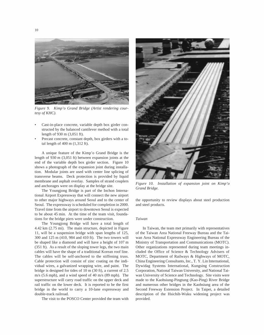
The Kimp’o Grand Bridge, shown in Figure 9, will carrythe Seoul Metropolitan outer ring road across the Han-GangRiver. The bridge has a total length of 3.5 km (2.18 mi) with2.28 km (1.42 mi) on elevated structure. The elevated portionincludes the following types of construction:
• Cast-in-place concrete, constant depth, box girders con-structed using a movable formwork system with a totallength of 950 m (3,116 ft).
Figure 8. Seo-Hae cable-stayed bridge (Artist rendering courtesy of KHC).
10
• Cast-in-place concrete, variable depth box girder con-structed by the balanced cantilever method with a totallength of 930 m (3,051 ft).
• Precast concrete, constant depth, box girders with a to-tal length of 400 m (1,312 ft).
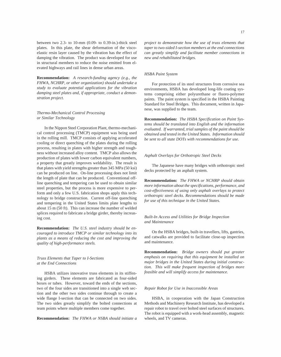
A unique feature of the Kimp’o Grand Bridge is thelength of 930 m (3,051 ft) between expansion joints at theend of the variable depth box girder section. Figure 10shows a photograph of the expansion joint during installa-tion. Modular joints are used with center line splicing oftransverse beams. Deck protection is provided by liquidmembrane and asphalt overlay. Samples of strand couplersand anchorages were on display at the bridge site.
The Youngjong Bridge is part of the Inchon Interna-tional Airport Expressway that will connect the new airportto other major highways around Seoul and to the center ofSeoul. The expressway is scheduled for completion in 2000.Travel time from the airport to downtown Seoul is expectedto be about 45 min. At the time of the team visit, founda-tions for the bridge piers were under construction.
The Youngjong Bridge will have a total length of4.42 km (2.75 mi). The main structure, depicted in Figure11, will be a suspension bridge with span lengths of 125,300 and 125 m (410, 984 and 410 ft). The two towers willbe shaped like a diamond and will have a height of 107 m(351 ft). As a result of the sloping tower legs, the two maincables will have the shape of a traditional Korean roof line.The cables will be self-anchored to the stiffening truss.Cable protection will consist of zinc coating on the indi-vidual wires, a galvanized wrapping wire, and paint. Thebridge is designed for tides of 10 m (30 ft), a current of 2.5m/s (5.6 mph), and a wind speed of 40 m/s (89 mph). Thesuperstructure will carry road traffic on the upper deck andrail traffic on the lower deck. It is reported to be the firstbridge in the world to carry a 10-lane expressway anddouble-track railroad.
The visit to the POSCO Center provided the team with
Figure 9. Kimp’o Grand Bridge (Artist rendering cour-tesy of KHC).
the opportunity to review displays about steel productionand steel products.
Taiwan
In Taiwan, the team met primarily with representativesof the Taiwan Area National Freeway Bureau and the Tai-wan Area National Expressway Engineering Bureau of theMinistry of Transportation and Communications (MOTC).Other organizations represented during team meetings in-cluded the Office of Science & Technology Advisers ofMOTC, Department of Railways & Highways of MOTC,China Engineering Consultants, Inc., T. Y. Lin International,Dywidag Systems International, Kungsing ConstructionCorporation, National Taiwan University, and National Tai-wan University of Science and Technology. Site visits weremade to the Kaohsiung-Pingtung (Kao-Ping) River Bridgeand numerous other bridges in the Kaohsiung area of theSecond Freeway Extension Project. In Taipei, a detaileddescription of the Hsichih-Wuku widening project wasprovided.
Figure 10. Installation of expansion joint on Kimp’oGrand Bridge.

11
The Taiwan Area National Freeway Bureau is respon-sible for road maintenance, traffic management, toll collec-tion, motorist services, and freeway widening. The TaiwanArea National Expressway Engineering Bureau has respon-sibility for planning, designing, and constructing the nationalexpressway network in Taiwan. The Bureau is organizedinto the headquarters office and district project offices. Theheadquarters office is responsible for project planning, de-sign, land acquisition, bidding, and construction. The dis-trict project offices are responsible for the management ofconstruction operations.
The Second Freeway Extension Project involves theconstruction of a 320-km (199-mi)-long main route plus fourbranch routes with a total length of 68 km (42 mi). Theproject includes the construction of 610 bridges and five
tunnels. Visits by the team were made to the Kao-PingRiver Bridge on the main route and numerous bridges on theKaohsiung Beltway and the Chishan Branch.
The main structure on the Kao-Ping River Bridge, de-picted in Figure 12, will be a single pylon cable-stayedbridge with span lengths of 330 and 180 m (1,083 and591 ft). The inverted Y-shaped concrete pylon will have atotal height of 180 m (591 ft). Foundations for the pylonwere constructed using a slurry wall. The superstructure forthe main span will be constructed with structural steel. Theside span will be built with prestressed concrete. The struc-tural steel segments will be assembled using all-welded con-struction on site at an area adjacent to the pylon. The seg-ments will be erected by lifting from the superstructure. Theconcrete segments will be cast-in-place on a falsework sys-
Figure 11. Youngjong Bridge (Artist rendering courtesy of KHC).
Figure 12. Kao-Ping River Bridge (Artist rendering courtesy of MOTC).

12
tem and will be constructed before the main span segmentsare erected. At the time of the visit, about two-thirds of theinclined legs of the pylon had been constructed, as shown inFigure 13.
The stay cables will consist of a 15.2-mm (0.6-in.)-diameter seven-wire strand system produced by VorspannTechnik of Austria. In this system, the individual strandsare coated with grease inside a polypropylene tube. Thewhole cable is enclosed inside a polypropylene tube that isfilled with wax. Wedge anchors are used at the ends of thestrands. When completed, the Kao-Ping River Bridge willbe the longest span bridge in Taiwan.
Other bridges on the second freeway extension projectare being constructed using the following systems:
• Constant depth, precast concrete segmental box girderserected by the balanced cantilever method with an erec-tion truss or cranes.
• Constant depth, cast-in-place concrete box girders con-structed span by span using an advancing shoring sys-tem.
• Constant depth, concrete box girders using the incre-mental launching method. Launching is accomplishedby pulling the rear end of the bridge towards the abut-ment using strands.
• Variable depth, cast-in-place concrete segmental boxgirders erected by the balanced cantilever method andtravelling formwork.
• Post-tensioned I-shaped concrete girders.• A combination of precast concrete slabs and cast-in-
place construction as illustrated in Figure 14.
For the balanced cantilever method with travellingformwork, the cantilevers were constructed with a one-halflength of segment out of balance to reduce the overturningmoment. End spans were also being constructed using formtravellers and falsework towers.
The Sun-Yat-Sen Freeway is a 373-km (232-mi) stretchof highway in northern Taiwan opened in 1978. Since thattime, traffic on the freeway has grown at an annual rate of10 percent. Additional lanes have been added using thecenter median and the shoulders to increase the capacity.However, further widening at grade level became impracti-cal. Consequently, it was decided to widen the freeway byadding elevated structures on each side of the existing free-way over a length of 21 km (13 mi). This project is knownas the Hsichih-Wuku widening project. For 13.5 km(8.4 mi), two lanes were added on each side and for 7.5 km(4.7 mi) three lanes were added. The widening provided ameans to separate long distance traffic from local trafficwith long-distance traffic using the new construction, asshown in Figure 15. The overall cost of the project includ-ing land acquisition and compensation was reported to beNT$31.2 billion ($1.1 billion U.S. in September 1997).
Several different construction methods were used forthe foundations of the 954 piers. These included reversecirculation drilled piles, full casing drilled piles, caissonfoundations, precast piles, and shallow footings. The 40.4-km (25.1-mi) length of elevated structure used many differ-Figure 13. Kao-Ping River Bridge under construction.
Figure 14. Combination of precast slabs and cast-in-placeconstruction (Diagrams by MOTC). (a) Underside of struc-ture; (b) Cross section
(a)
(b)

13
ent structural types. Approximately one-third of the super-structure was built using prestressed concrete I-girders andabout one-quarter used steel box girders. Other types in-cluded cast-in-place, segmental box girders built by the bal-anced cantilever method; cast-in-place, double-tee girders;precast concrete box girders; precast, prestressed single-teegirders; and hollow slabs.
In Taipei, the team visited the Freeway Traffic Surveil-lance and Control Center of the Taiwan Area National Free-way Bureau. The control center uses an “on-line real time”integrated system and uses automated monitoring of trafficconditions with roadside equipment, centralized processingand control systems, and information transmission and com-munications equipment.
Figure 15. Hsichih-Wuku widening project.
Nonsegregating Flowable Concretes
For the cable anchorages of the Akashi-Kaikyo Bridge,HSBA used a self-healing highly flowable nonsegregatingconcrete. The concrete mix included a low-heat cement, lime-stone powder, superplasticizer, and 40-mm (1.6-in.) maxi-mum size coarse aggregate. The concrete was specified tohave a flow of 500 mm (120 in.), air content of 4 percent, anda 91-day compressive strength of 30 MPa (4,350 psi).
Recommendation: The FHWA, in cooperation with StateDOTs, should sponsor high-performance concrete demon-stration projects to show the advantages of using flowableconcretes in areas of congested reinforcement. Informationon this product should be made available to the AmericanConcrete Institute, National Ready Mixed Concrete Asso-ciation, and the Portland Cement Association.
Computerized Assembly and Testing System (CATS) for SteelComponents
The Yokogawa Bridge Corporation has developed a newcomputerized system to simulate erection of complicatedstructures and to eliminate the need for shop assembly ofbridges. CATS uses photogrammetry methods with four cam-eras to take 3-D pictures of each element. The shape anddimensions of the members are obtained by linking the datafrom the cameras and other measuring devices. The membersare then “shop assembled” in simulation on the computerscreen using software developed for that purpose. Any cor-rections that need to be made to the members are identified.Actual measurements are compared with the design data toidentify production errors. This innovation removes the needfor shop assembly, while ensuring accuracy. In addition, in-formation, such as camber and joint widths, for assemblingthe bridge at the construction site is developed.
Recommendation: CATS should be studied further by theAmerican Institute of Steel Construction, the American Ironand Steel Institute, and the National Steel Bridge Alliance,and research considered to develop a system that can beused in the United States. Copies of this scanning reviewreport, including the translation of the CATS brochure,should be made available to trade associations for distribu-tion to their members.
Nonmetallic Removable Back-Up Bars for One-Sided Welding
HSBA makes use of steel bridge decks for all its majorbridge projects. These are orthotropic bridge decks fieldwelded from one side only. HSBA uses a temporary, non-metallic back-up bar attached to the bottom of the deck plateusing adhesive strips on the bar. The bar has a concavesurface on the side attached to the deck to allow some over-
SUMMARY OF RECOMMENDEDTECHNOLOGIES
On the basis of the observations made during the scan-ning review, the team developed a list of 30 topics for pos-sible application by public and private agencies in the UnitedStates. The list was then divided into 6 high-priority, 7medium-priority topics, and 17 other topics for consider-ation at a later date. A summary of the topics and recom-mendations for implementation are given in this section.More details of the technologies are given later.
High-Priority Topics
Dimple Pipe for Exterior of Stay Cables
Vibrations of stay cables can be a serious problem un-der certain weather conditions. On the Tatara Bridge inJapan, a black polyethylene pipe with a dimpled outer sur-face is used to reduce vibrations caused by wind and rain.
Recommendation: The FHWA should make informationabout the pipe available to the U.S. bridge engineeringcommunity.

14
reinforcement on the bottom side of the weld. The bar canbe easily removed for inspection of the weld after comple-tion. The back-up bar used in Japan appeared to differ fromthe ceramic bars available in the United States, and it wasimplied that the cost of the Japanese bars was much lower.Potentially, the use of a similar back-up bar with adhesivestrips in the United States can provide cost-effective qualityimprovements in U.S. welding processes.
Recommendation: A research funding agency (e.g., theFHWA, NCHRP, or other organization), in cooperation withthe American Institute of Steel Construction, AmericanWelding Society, and the National Steel Bridge Alliance,should perform research to investigate one-sided weldingusing the nonmetallic back-up bars that are being used inJapan. Possible applications in the United States should bedetermined.
Dry Air Injection System for CorrosionProtection of Cables
The latest HSBA system for corrosion protection of themain cables of suspension bridges consists of the injectionof dry air into the main cable interior. The goal is to keepthe humidity level inside the cable below 40 percent. Inaddition to the use of this system on new suspension bridgesthat will not have any anti-corrosion paste installed, HSBAplans to retrofit suspension bridges that were constructedwith an internal anti-corrosion paste. These built structuresare quite similar to suspension bridges in service in theUnited States today.
Recommendation: A research-funding agency (e.g., theFHWA, NCHRP, or other organization) should perform amore detailed investigation of the dry air injection system todetermine how it can be used on existing and future bridgesin the United States. Although HSBA is using the conceptfor suspension bridges, its possible use in other applicationssuch as cable-stayed bridges should be evaluated.
Special Paint Primer
In cooperation with major steel producers, PWRI hasbeen testing and evaluating a significant improvement in cor-rosion protection technology. This technology is a new spray-on product that was referred to as “suspicious primer.” Thespray-on primer product stimulates the formation of the chro-mium steels. This product was successfully tested by PWRIand sent to all major steel suppliers in Japan to have addi-tional independent testing conducted. Over the last year, testresults have been positive. The product would be used on allbridge steels, regardless of grade and chemical make-up. The
product is commercially available from Sumitomo MetalIndustries, Ltd., as the “Weather-Act Method.” Successfulusage of this product has the potential to enhance protectionpractices of steel bridges in the United States.
Recommendation: The FHWA should obtain detailed in-formation about this product from Sumitomo Metal Indus-tries. If warranted, trial samples should be obtained andtested in the United States. Information should be madeavailable to state DOTs.
Medium-Priority Topics
Balanced Cantilever Construction with Alternate SegmentsOffset by 1/2-Segment Length
The technique of constructing balanced cantilever cast-in-place concrete bridges with alternate segments offset by a1/2-segment length is used in Taiwan to reduce the out-of-balance moment at the pier.
Recommendation: The FHWA should provide this scan-ning review report to the American Segmental Bridge Insti-tute (ASBI) for distribution to its members. Owners, design-ers, and contractors should consider using this technique inconstruction.
Full Cantilever Erection for End Spans of BalancedCantilever Bridges
In Taiwan, it was noted that end spans were constructedusing form travelers and the cantilever method. A tempo-rary pier was provided near midspan to allow the cantilever-ing to continue to the abutment. Hydraulic jacks were in-stalled between the temporary pier and the box girders toadjust for any settlements. This technique eliminated theneed for continuous shoring that is frequently used in theUnited States.
Recommendation: The FHWA should provide this scan-ning review report to ASBI for distribution to its members.Owners, designers, and contractors should consider usingthis concept for end span construction of bridges erected bythe cantilever method.
Nonseparating (Desegregating) Tremie Concretes
For the underwater concrete tower foundations of theAkashi-Kaikyo Bridge, a special nonseparating concrete wasused. The concrete contained a high-range water-reducingadmixture to achieve flowability and an anti-washout ad-

15
mixture to obtain viscosity. An anti-washout admixture isavailable from at least one supplier in the United States, butis not used extensively.
Recommendation: The FHWA, in cooperation with stateDOTs, should sponsor high-performance concrete demon-stration projects to show the advantages of using non-sepa-rating concretes for underwater construction. Informationon this product should be made available to the AmericanConcrete Institute, the National Ready Mixed Concrete As-sociation, and the Portland Cement Association.
19-Wire Prestressing Strands
The Japanese have developed 19-wire prestressingstrand with diameters of 17.8, 19.3, 20.3, and 21.8 mm (0.70,0.76, 0.80, and 0.86 in.). The strands consist of two concen-tric layers of wire wrapped around a center wire. Each con-centric layer consists of nine wires. The strand has a speci-fied minimum strength slightly less than Grade 270 strand.The largest strand has a minimum breaking strength of 3.1times the strength of a 12.7-mm (0.5-in)-diameter Grade 270strand. The 19-wire strand developed in Japan has potentialapplication for transverse post-tensioning of bridge decksand prestressing high-strength concrete beams.
Recommendation: A research-funding agency (e.g., theFHWA, NCHRP, or other agency) should develop or under-take a research project to develop design information foruse with 19-wire strand. Design recommendations for theAASHTO Specifications should be developed.
Wrapping Wire with Interlocking Cross Section
On the Kurushima Bridges, a wrapping wire with anS-shaped cross section, developed by Nippon Steel Corpo-ration, will be used to wrap the main cables. The crosssection of the wire is designed so that the two legs of the Sinterlock. The interlocking provides a tighter seal againstmoisture penetration compared to wrapping with conven-tional wire having a circular cross section.
Recommendation: The FHWA, in cooperation with anowner, should pursue the use of interlocking wire on thenext suspension bridge to be built in the United States.
Flame or Thermal Spray Metallizing
PWRI has been working with an improved thermalspray system. The new thermal spray system uses lighterequipment and considerably less heat. The primary innova-
tion is the metal used for the thermal spray, which is a 50:50combination by volume of zinc and aluminum. It is ex-pected that this system offers the best alternative for thermalspray applications. At the present time, its use has beenreserved for long-span bridges because of the high cost.
Recommendation: The FHWA should incorporate tests ofthe improved thermal spray system and the 50:50 zinc-aluminum spray into existing research projects for methodsof controlling corrosion.
Translation of Relevant Sections of the HSBASpecifications into English
HSBA has developed its own specifications for long-span bridges.
Recommendation: The FHWA should have relevantsections of the HSBA specifications translated into Eng-lish and distribute the translations to appropriate organiza-tions.
Other Topics
Research on Punching Shear Failure
In all three countries, the topic of punching shear fail-ures of bridge decks associated with cracking and fatiguewas mentioned. Each country had a slightly different expla-nation for the mechanism.
Recommendation: A research-funding agency (e.g., theFHWA, NCHRP, or other organization) should support aresearch project to determine if punching shear failurecaused by fatigue of concrete is a failure mode that needs tobe considered in the design of bridges in the United States.If required, appropriate design recommendations for theAASHTO Specifications should be developed.
Bolted Connections for Earthquake Resistance
The Japanese are evaluating the use of bolted connec-tions to improve seismic resistance of steel structures.
Recommendation: The American Institute of Steel Con-struction, American Iron and Steel Institute, FHWA, or Na-tional Science Foundation should evaluate this concept andconsider initiation of a project to determine if the use ofbolted connections in bridge structures or buildings willimprove their seismic resistance. If appropriate, design pro-cedures should be developed.

16
Mechanical Damping Devices to Control Vibrations ofSteel Towers
HSBA has incorporated tuned mass dampers into itsbridge towers to control vibrations both during constructionand during the service life of the bridge. In the UnitedStates, this technology has been limited to buildings.
Recommendation: Owners and designers of tall bridgestructures are encouraged to consider this approach for newstructures and as a retrofit for existing structures,
Forced Vibration Tests on Completed Bridges
The response of large bridges to wind and earthquakeloads is an important aspect of design. Design assumptionsabout actual dynamic characteristics, such as natural fre-quencies and damping characteristics, can be determined byforced vibration tests on completed bridges. Informationcan be used to improve design procedures.
Recommendation: A national research effort should beinitiated to evaluate the benefit of full-scale dynamic testingof bridges in the United States.
Special Railway Expansion Joints for FlexibleLong-Span Bridges
On the Kojima-Sakaide Route, which carries a railroadon the lower deck, special joints were needed to accommo-date rotation and longitudinal movements.
Recommendation: The FHWA or NCHRP should distrib-ute copies of this scanning review report to the AAR, theAmerican Railway Engineering and Maintenance Associa-tion, and the FRA informing them about the railway expan-sion joints used by HSBA.
Pneumatic Caissons with Remote Control Equipment forUnderwater Construction
Construction of each tower foundation for the Young-jong Bridge uses pneumatic caissons, six remote-controlledexcavators, and closed-circuit television. Instrumentation isprovided to measure water levels, current speed, caisson el-evations, and tilt. Construction is monitored and controlledfrom a separate control room.
Recommendation: The FHWA should provide this scan-ning review report and other information about the use ofremote-controlled equipment for underwater constructionto the state DOTs and contractor’s trade associations fordistribution to their members.
Slurry-Wall Construction for Tower Foundations
On the Kao-Ping River Bridge, the foundation for themain pier was being constructed using slurry walls to carrythe pier loads.
Recommendation: The technique of using slurry walls totransfer pier loads to bedrock should be considered by de-signers as an alternative foundation system to reduce theamount of excavation required.
High-Strength Silicon Steel Wire
In Japan, a high-strength silicon steel wire with tensilestrength of 180 kgf/mm2 (256 ksi) has been developed foruse in suspension cables in long-span bridges. The cablewas first used in the Akashi-Kaikyo Bridge. HSBA reportedthat the bridge design would have required four main cableswith traditional strength wire. The high-strength siliconwire, in combination with a lower factor of safety for thecable, allowed the use of only two cables, thereby signifi-cantly reducing the weight and cost of the structure.
Recommendation: The FHWA, in cooperation with wireproducers, should conduct research to demonstrate the prop-erties of high-strength silicon wire for use in suspensioncables and to evaluate its potential use in other applications.
Steels Containing a Higher Percentage of Nickel
The Japanese have a weathering steel that is essentiallyequivalent to U.S. steel grades A709-50W and 70W, respec-tively, with the exception that the nickel content is increasedfrom about 0.3 percent to about 3 percent. Similar steels areavailable in the United States under the ASTM A710 speci-fication, but steels meeting this specification are not cur-rently allowed by AASHTO for use in bridges.
Recommendation: A research-funding agency (e.g., theFHWA, NCHRP, or other organization), should initiate re-search to evaluate corrosion-resistant steels currently avail-able under the ASTM A710 specification to determine theirsuitability for use in bridge structures. If it is determinedthat the properties are adequate, the AASHTO MaterialsSpecifications should be modified to allow their use. Thiswill give engineers another tool for use in difficult environ-ments.
Vibration Damping Steel Plates
The Japanese have produced a composite vibrationdamping steel plate that consists of a 0.15- to 0.3-mm(0.006- to 0.012-in.) layer of visco-elastic resin sandwiched
17
between two 2.3- to 10-mm (0.09- to 0.39-in.)-thick steelplates. In this plate, the shear deformation of the visco-elastic resin layer caused by the vibration has the effect ofdamping the vibration. The product was developed for usein structural members to reduce the noise emitted from el-evated highways and rail lines in dense urban areas.
Recommendation: A research-funding agency (e.g., theFHWA, NCHRP, or other organization) should undertake astudy to evaluate potential applications for the vibrationdamping steel plates and, if appropriate, conduct a demon-stration project.
Thermo-Mechanical Control Processingor Similar Technology
In the Nippon Steel Corporation Plant, thermo-mechani-cal control processing (TMCP) equipment was being usedin the rolling mill. TMCP consists of applying acceleratedcooling or direct quenching of the plates during the rollingprocess, resulting in plates with higher strength and tough-ness without increased alloy content. TMCP also allows theproduction of plates with lower carbon equivalent numbers,a property that greatly improves weldability. The result isthat plates with yield strengths greater than 345 MPa (50 ksi)can be produced on line. On-line processing does not limitthe length of plate that can be produced. Conventional off-line quenching and tempering can be used to obtain similarsteel properties, but the process is more expensive to per-form and only a few U.S. fabrication shops apply this tech-nology to bridge construction. Current off-line quenchingand tempering in the United States limits plate lengths toabout 15 m (50 ft). This can increase the number of weldedsplices required to fabricate a bridge girder, thereby increas-ing cost.
Recommendation: The U.S. steel industry should be en-couraged to introduce TMCP or similar technology into itsplants as a means of reducing the cost and improving thequality of high-performance steels.
Truss Elements that Taper to I-Sectionsat the End Connections
HSBA utilizes innovative truss elements in its stiffen-ing girders. These elements are fabricated as four-sidedboxes or tubes. However, toward the ends of the sections,two of the four sides are transitioned into a single web sec-tion and the other two sides continue through to create awide flange I-section that can be connected on two sides.The two sides greatly simplify the bolted connections atteam points where multiple members come together.
Recommendation: The FHWA or NSBA should initiate a
project to demonstrate how the use of truss elements thattaper to two-sided I-section members at the end connectionscan greatly simplify and facilitate member connections innew and rehabilitated bridges.
HSBA Paint System
For protection of its steel structures from corrosive seaenvironments, HSBA has developed long-life coating sys-tems comprising either polyurethane or fluoro-polymerpaints. The paint system is specified in the HSBA PaintingStandard for Steel Bridges. This document, written in Japa-nese, was supplied to the team.
Recommendation: The HSBA Specification on Paint Sys-tems should be translated into English and the informationevaluated. If warranted, trial samples of the paint should beobtained and tested in the United States. Information shouldbe sent to all state DOTs with recommendations for use.
Asphalt Overlays for Orthotropic Steel Decks
The Japanese have many bridges with orthotropic steeldecks protected by an asphalt system.
Recommendation: The FHWA or NCHRP should obtainmore information about the specifications, performance, andcost-effectiveness of using only asphalt overlays to protectorthotropic steel decks. Recommendations should be madefor use of this technique in the United States.
Built-In Access and Utilities for Bridge Inspectionand Maintenance
On the HSBA bridges, built-in travellers, lifts, gantries,and catwalks are provided to facilitate close-up inspectionand maintenance.
Recommendation: Bridge owners should put greateremphasis on requiring that this equipment be installed onmajor bridges in the United States during initial construc-tion. This will make frequent inspection of bridges morefeasible and will simplify access for maintenance.
Repair Robot for Use in Inaccessible Areas
HSBA, in cooperation with the Japan ConstructionMethods and Machinery Research Institute, has developed arepair robot to travel over bolted steel surfaces of structures.The robot is equipped with a work-head assembly, magneticwheels, and TV cameras.

18
Recommendation: The FHWA should evaluate potentialapplications of the HSBA robot on U.S. bridges and deter-mine if its use should be pursued.
Public Relations Programs for Major Projects
Many of the construction sites had excellent visitors’ cen-ters and excellent informational materials for distribution.
Recommendation: Bridge owners and the FHWA shoulddevelop informational packages for all major bridge androadway projects to promote public and professional aware-ness of the benefits of bridge and highway investments.
DESIGN STANDARDS, CODES, ANDSPECIFICATIONS
Design standards, codes, and specifications in the threecountries use an approach similar to that used in the UnitedStates. Design live loads are being driven upward by theneed to design for heavier and multiple trucks. In Japan,special emphasis is now being given to seismic design.Specific items for each country are given in the followingsections.
Japan
Design specifications for highway bridges in Japan areprepared by the Japan Road Association, which is equiva-lent to AASHTO. The specifications are developed by com-mittees in a similar manner to the AASHTO specifications.The Highway Bridge Specifications consist of five parts:
1. General2. Steel Bridges3. Concrete Bridges4. Substructures5. Seismic Design
In general, bridge design in both concrete and steel isbased on the allowable stress approach. However, seismicdesign is based on ultimate strength. The design specifica-tions reference Japanese Industrial Standards (JIS) for qual-ity control and mechanical properties of materials. The JISused to be revised on a 10-year cycle. However, recentevents have resulted in more frequent changes. When mate-rials not covered by JIS are used, technical experts are con-sulted and a committee review process is adopted. TheHighway Bridge Specifications apply to span lengths up to200 m (656 ft) and are revised every 4 to 5 years. The seis-mic design specification was extensively revised after theGreat Hanshin Earthquake in 1995.
A guideline for limit state design of concrete structureshas been developed by the Japan Society of Civil Engineers(JSCE). Introduction of limit state design into practice hasbeen limited because there are no specific criteria to deter-mine the appropriate load and resistance factors. For frac-ture critical steel members, no damage is allowed under ser-vice loads. Partial damage is allowed under unlikely eventssuch as unexpected live loads and big earthquakes, but cata-strophic failure is not allowed. Redundancy with fracturecritical members has not been well recognized and there areno provisions for redundancy. For seismic design, there aretwo levels. At Level I, the structure is designed to survivewith no damage. At Level II, some damage is allowed. TheJapanese have seen evidence of fracture of steel membersfrom low cycle fatigue occurring as a result of seismic load-ing. Strains were in the range of 10 to 20 percent.
Since HSBA deals with combined road and railwaybridges and with span lengths longer than 200 m (656 ft),they have developed their own design standards for super-structure design, wind-resistant design, seismic design, andsubstructure design. These standards allow the use of highertensile strength steels. HSBA standards use the allowablestress design approach with some movement toward a limitstates method which HSBA sees as an international ap-proach. The use of a lower factor of safety for the maincables of the Akashi-Kaikyo Bridge because of the highdead load reflects a limit states approach. A copy of theHSBA specifications in Japanese was given to the team.
South Korea
Codes and specifications in South Korea are revisedmainly by the Ministry of Construction and Transportationon a cycle of about 6 years. The revisions are made by acommittee that performs research work and reports to aspecialist consultant team that develops the final revisions.The Ministry informs the relevant authorities for imple-mentation.
The design approach in South Korea is very similar tothat in the AASHTO Standard Specifications for HighwayBridges. However, 33 percent larger truck loads are useddue to the increasing number of larger sized vehicles in thecountry. Other design loads include ship impact and tem-perature gradients. Steel structures are designed using thepermissible stress design method. Prestressed concretestructures are designed for service loads and then checkedfor factored loads. The Koreans anticipate that the loadand resistance factor design method will be used in thefuture.
For seismic design, the country is divided into twozones for selection of acceleration factors. Single-modeanalysis methods are generally used, but for structures re-quiring more complex analysis, multi-mode methods areused. The seismic design standards are in the process ofbeing rewritten.

19
Taiwan
In Taiwan, bridge design is based on the HighwayBridge Specifications published by the Ministry of Trans-portation and Communications. Reference is also made tothe AASHTO Standard Specifications for Highway Bridgesand the CALTRANS Bridge Design Specifications Manual.The current specifications were developed in 1989. Theyare being updated and should be complete by 1999. It alsoappeared that the basic specifications are modified for spe-cific projects.
A live load equivalent to HS20-44 + 25% is used. Theservice load design method is used for foundation design.The load factor design method is used for columns. Ser-vice load design or load factor design is used for the super-structure.
Recommendations on Design Standards,Codes, and Specifications
The AASHTO LRFD Bridge Design Specifications mayrepresent a model document that could be used in thesecountries as they move toward an LRFD design approach.The United States should stay current on the Japanese pro-visions for wind loads, water loads, scour, seismic design,and new materials. The team recommends that FHWA ar-range for the translation into English of the relevant sectionsof the HSBA specifications.
DESIGN AND CONSTRUCTION PRACTICES
Japan
In Japan, it is a requirement that bridges and viaducts beconstructed economically and effectively in a short periodof time to meet the rapid increase in traffic. The teamlearned that JH and PWRI have been directed to lower costsby 10 percent and to introduce life-cycle costing. The teamalso observed that both gasoline taxes and tolls are relativelymuch higher than in the United States.
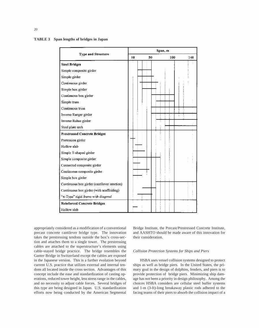
A breakdown of the various types of structures and theirapplicable span lengths as published by JH is given inTable 3. Steel structures are used for longer span lengths,whereas in the United States concrete is more competitivefor longer span lengths.
Many of the superstructures of existing Japanese bridgesare built of steel to reduce weight and the resulting seismicforces. These structures are typically plate girder bridgesbecause of economy and ease of fabrication. Design is gen-erally based on noncomposite action between the concretedeck and steel girders because of ease of maintenance. Boxgirders are used where girder depth is limited and on smallradius curves. Elevated viaducts are used extensively inurban areas because of the shortage of land. Steel substruc-
tures are used to minimize the size of the footprint. Greatemphasis is placed on doing as much work as possible in theprefabrication plant and minimizing labor at the expense ofmaterial weight. For longer spans, truss bridges, cable-stayed bridges, and suspension bridges are used. A uniquefeature noticed on the HSBA routes was the use of continu-ous suspension bridges such as the Kurushima Bridges andBisan-Seto Bridges and the use of continuous cable-stayedbridges such as the Hitsuishijima and Iwakurojima Bridges.
Concrete bridges consist of reinforced concrete boxgirders, prestressed concrete composite girders, and pre-stressed concrete box girders erected using the cantilevermethod. Current emphasis is directed to methods of mecha-nizing the construction process to reduce labor requirements.Reinforced concrete box beams are used on expressways forbridges with span lengths of 15 to 17 m (49 to 56 ft). Pre-stressed concrete girders are the standard for bridges withspan lengths of about 30 m (100 ft). For long span lengths,box girders constructed by the balanced cantilever methodare used. The use of precast concrete segments is leading toshorter construction times.
For short span bridges, standard plans and details areused and the process is largely automated. Although it wasdifficult to obtain precise numbers, there is a trend towardthe greater utilization of concrete superstructures as steel isbecoming less competitive than precast concrete for spanlengths of 60 to 100 m (200 to 330 ft).
During the design phase of special structures, severalalternate types of bridges and construction methods are con-sidered but only one final design is prepared for bidding.HSBA makes a complete independent check on the analysisof all its major bridges. After award of the contract, onlysmall changes may be proposed by the contractor. There isno incentive for contractors to submit alternative designs asmajor changes are only made by the owner and, in this situ-ation, the job price is recalculated and the contractor returnsall savings. The Japanese have limited experience with valueengineering and design-build contracts. In some situations,JH does the basic design and allows the contractor to do thedetailed design. The usual bidding process also involvesseparate contracts for the substructure and the superstruc-ture, whereas for most bridges in the United States, only onecontract is used. The use of two contracts was evident onseveral multi-span bridges where the substructures for manyspans were complete but the superstructure erection was along way behind.
Extradosed Concrete Bridges
JH has built and is considering many innovative struc-tures. Among the innovative types that it has developed isone described as the “Extradosed Concrete Bridge.” A pho-tograph of this type of bridge is shown in Figure 16. Thisbridge is similar in appearance to a small cable-stayed bridgebut with a low tower height. However, the bridge is more
20
appropriately considered as a modification of a conventionalprecast concrete cantilever bridge type. The innovationtakes the prestressing tendons outside the box’s cross-sec-tion and attaches them to a single tower. The prestressingcables are attached to the superstructure’s elements usingcable-stayed bridge practice. The bridge resembles theGanter Bridge in Switzerland except the cables are exposedin the Japanese version. This is a further evolution beyondcurrent U.S. practice that utilizes external and internal ten-dons all located inside the cross section. Advantages of thisconcept include the ease and standardization of casting op-erations, reduced tower height, less stress range in the cables,and no necessity to adjust cable forces. Several bridges ofthis type are being designed in Japan. U.S. standardizationefforts now being conducted by the American Segmental
Bridge Institute, the Precast/Prestressed Concrete Institute,and AASHTO should be made aware of this innovation fortheir consideration.
Collision Protection Systems for Ships and Piers
HSBA uses vessel collision systems designed to protectships as well as bridge piers. In the United States, the pri-mary goal in the design of dolphins, fenders, and piers is toprovide protection of bridge piers. Minimizing ship dam-age has not been a priority in design philosophy. Among thechoices HSBA considers are cellular steel buffer systemsand 1-m (3-ft)-long breakaway plastic rods adhered to thefacing teams of their piers to absorb the collision impact of a
TABLE 3 Span lengths of bridges in Japan

21
vessel. This minimizes ship damage and protects the pier.The pier protection system used on the Akashi-KaikyoBridge is shown in Figure 17. The concept is a major inno-vation. Any number of configurations can be made once theconcept is considered in design.
Concrete Deck Fatigue
The Japanese think that repeated loads are a primaryfactor that is contributing to premature failure of their con-crete bridge decks. It was reported that bridges are sub-jected to illegal overloads that are much greater than designloads. PWRI explained that the failure mechanism startswith the formation of transverse cracks from shrinkage andoverloads. These cracks grow larger under repeated liveloads. Longitudinal cracks then begin to appear possiblycaused by overloads. At some point, the cracks start topropagate more in a shear mode than a bending mode. Thisdivides the deck into a series of rectangular blocks. Waterpenetrates the cracks and leaches out the cement which fur-ther reduces the shear capacity. Finally, a punching sheartype of failure occurs resulting in holes in the deck. Forbridges designed before 1980, punching shear of decks wasnot considered in design. It is unknown how much of aneffect corrosion of reinforcing steel plays in acceleratingthis process. The Japanese are not sure of the exact failuremode for this phenomenon. Consequently, bridges are de-signed to be non-composite.
PWRI is actively researching the fatigue performanceof full-scale concrete deck teams using new hydraulic equip-ment capable of applying a moving wheel load in the labora-tory. Currently, no research results have been published.
PWRI is also using weigh-in-motion systems to determineactual truck loads.
This type of punching failure has been observed in theUnited States. However, chloride penetration and corrosionof steel reinforcement have been identified as the primarycauses. In the United States, epoxy-coated steel reinforce-ment or other corrosion protection systems are expected toreduce this type of problem for most modern bridge decks.If the mechanism of deterioration is more fatigue relatedthan corrosion related, it is possible that deck failures willoccur, even with the corrosion protection systems. Unfortu-nately, it will take many years before this is known. UnderNCHRP Project 12-37, factors contributing to transversecracking of newly constructed bridge decks were identified.However, the project did not address the effect of transversecracks or the structural integrity of bridge decks or the causesand effects of longitudinal cracks. Consequently, this prob-lem should be studied further in the United States.
Bolted Connections for Earthquake Resistance
During the visit to the Steel Structures DevelopmentCenter of the Research and Engineering Center at NipponSteel Corporation, tests were being performed on full-sizebolted beam-column connections for rectangular columnmembers. The tests were being conducted using short dura-tion real-time dynamic displacements to represent earth-quakes. The objectives of the research were to develop ret-rofitting methods and to develop design codes for largeearthquake loadings. During the Great Hanshin Earthquake,weaknesses occurred in some welded corner connections.This has been duplicated in the laboratory. Subsequent tests
Figure 16. Extradosed concrete bridge (Photo by JH).

22
have been used to examine an alternative configuration us-ing bolted connections, angle reinforcement, and corner di-agonal plates.
Quality Control
For quality control during construction, the contractoris required to submit a working plan to the agency. Thecontractor has primary responsibility for quality control.The team was informed that HSBA and JH do not performconstruction inspection. The system is based on credibilitybetween the agency and the contractor. The contractorchecks that materials conform to JIS and the manufacturerprovides a warranty. For materials not covered by JIS, aspecial warranty is required. By comparison, most agenciesin the United States provide their own inspectors for bridgeconstruction.
The team was impressed with the precision used by theJapanese in construction. A high degree of precision is nec-essary because of the extensive use of off-site prefabricationwhich does not allow for large variances on the site. On theAkashi-Kaikyo Bridge, the tops of the towers were within20 mm (3/4 in.) of their planned location. At Kurushima,the caissons were precisely positioned, the verticality of thetowers was carefully checked and the superstructure waserected from a self-positioning barge. This self-positioningsystem used triangulation with two fixed light wave sourceson land to automatically control the position of the barge inthe strong currents of the straits. This application is anexample of the use of a global positioning system in con-struction.
On-Site Monitoring
HSBA also does extensive on-site monitoring to deter-mine the actual dynamic characteristics of the bridges for com-parison with design assumptions. For example, structures aremonitored for accelerations from both wind and earthquakes.During construction of the Akashi-Kaikyo Bridge, the towerswere excited with vibrators to verify that the tuned mass damp-ers performed as planned. The superstructure on one of theKojima-Sakaide Route bridges was also subjected to forcedvibration testing. By contrast, very little testing of completedbridges is performed in the United States.
Expansion Joints
On the long structures built by HSBA, special expan-sion joints are needed to accommodate the longitudinalmovements. This link-type joint is patented by HSBA andSumitomo Metal Company. The riding surface of the ex-pansion joint on the Akashi-Kaikyo Bridge is shown in Fig-Figure 17. Pier protection on Akashi-Kaikyo Bridge. (a)
Schematic (Diagram by HSBA); (b) Base of pier.
(a)
(b)

23
ure 18. The scissor-type arrangement that supports the steelfingers is shown in Figure 19.
On the Kojima-Sakaide Route, which carries a railroadon the lower deck, special joints were needed to accommo-date rotation as well as expansion and contraction. Figure20 shows two schematic diagrams of a joint that spreads thechange in slope over several locations separated by about15 m (50 ft). In addition to accommodating rotation, these
joints must accommodate longitudinal movement. A sche-matic of the railway expansion joint system that can accom-modate movement as large as 1.5 m (5 ft) is shown in Figure21. This system is used between the end anchorage and thefirst team of the stiffening truss. The receiving girder andside girders are fixed to the anchorage. The transition girderhas one end that slides on the anchorage while the other endrests on a beam of the truss. The insertion girder has oneend free to slide on the anchorage while the other end restson and moves with the transition girder. The rails are fixedto each girder using direct fastening devices. Half sectionsof rails are used on the side girders and on the insertiongirders to allow for longitudinal movement. Guide rails arealso provided to protect trains from derailment.
Figure 18. Riding surface of the expansion joint on theAkashi-Kaikyo Bridge.
Figure 19. Scissors expansion joint (a) HSBA scissors ex-pansion joint (Diagram by HSBA); (b) Underside of expan-sion joint on Akashi-Kaikyo Bridge.
(b)
(a)
Figure 20. Expansion joint to accommodate changes inslope (Diagram by HSBA).
Figure 21. Railway expansion joint used on the Kojima-Sakaide Route (Diagram by HSBA).

24
Cables
For suspension bridges and cable-stayed bridges on theHSBA routes, the following observations were made:
• Parallel strand cables were used for the main cables ofthe suspension bridges
• Lead/copper sockets were used to anchor the strands ofthe suspension bridges A strand anchor on the Akashi-Kaikyo Bridge is shown in Figure 22.
• A black polyethylene pipe used for the outer layer ofcable protection on the Tatara Bridge has a dimpledouter surface to reduce vibrations caused by wind andrain. A photograph of the pipe is shown in Figure 23.
The dimpled pipe surface may reduce or stop the vibra-tions that have occurred with smooth pipe used on someU.S. bridges.
Pre-Manufactured Drainage System Within the Curb
Along the approaches to the Akashi-Kaikyo Bridge, deckdrainage is handled in an innovative manner. The edge of theroadway surface is bounded by a pre-manufactured steel bar-rier curb. This curb has continuous perforations that allow thedeck to drain into the curbs themselves. Inside the curbs arepipes that carry the drainage back to the abutments. Thesystem is designed to allow routine maintenance and clean-ing. Ponding is minimized because the drainage is a continu-ous perforated strip. Because the system is prefabricated andnonintrusive to the deck or to the superstructure, corrosion isminimized. The concept of this innovation is not used in theUnited States but is a simple one to introduce with either steelor precast concrete barriers.
South Korea
In South Korea, the team was informed that, on a na-tional basis, approximately 95 percent of the bridges are builtwith concrete. In the KHC system, approximately 80 per-cent of the bridges are concrete and, around the big cities,that amount drops to 40 percent. Most of the prestressedconcrete bridges are precast on site and then post-tensionedusing 12.7-or 15.2-mm (0.5- or 0.6-in.)-diameter strand sys-
Figure 22. Strand anchorage on the Akashi-KaikyoBridge.
Figure 23. Dimple pipe used on stay cables on the TataraBridge.

25
tems. This is the opposite of U.S. practice where most con-crete bridges are plant produced with 12.7-mm (0.5-in.)-diameter strand. Steel bridges are becoming more competi-tive in Korea as steel costs are becoming less and labor costsfor concrete construction are increasing.
In the past, it was estimated that steel and concretebridges would have design lives of 100 and 50 years respec-tively. Today, as a result of the truck traffic weight andvolume, these estimates have been arbitrarily reduced to 50and 25 years, respectively. The engineering basis for therevised numbers was not provided. KHC has a policy thatpermits the development of alternate designs but has limitedexperience at doing this. Contractors may also propose al-ternatives. Design of concrete slab bridges, steel bridges,and bridge details is standardized. It was estimated thatapproximately 60 percent of structural calculations and 30percent of drawing preparations are automated.
The road construction budget in South Korea has in-creased by approximately 19 percent per annum over thepast 5 years. Despite this increase, further expansion isneeded to keep pace with growing demand. In the past,approximately 90 percent of the funding was derived fromoil and gasoline taxes. Alternative funding policies are be-ing developed for the future. Taxes on vehicle purchase andregistration will be reduced and a special excise tax on oilwill be raised. Other capital will be raised through the useof government bonds, private funds, new taxes on tires andlubricating oil, and private capital investments. Generally,private sector finances are expected to be about 60 to 70percent of the project amount with the government provid-ing the balance. For public road construction projects, theKorean government provides the land to the private sector.The new Inchon Airport Expressway project is the first touse private capital.
Designers are generally selected by the client through aprocess of prequalification and evaluation of subsequent pro-posals including costs. Designers for large projects are se-lected on the basis of prequalification and public bids. Ex-cellent performance by a designer can lead to the designationof “Excellent Contractor” by MOCT. This distinction re-sults in additional preference in the prequalification evalua-tion. Excellent Contractors also have the opportunity totake part in limited competition projects. On the other hand,designers that make a serious error receive demerits inprequalification.
The issue of punching shear failures in concrete deckswas also raised in South Korea. The Korea Institute of Tech-nology reports that cracks occur as a result of drying shrink-age. These cracks further increase as a result of traffic loadsand penetrate through the deck thickness. Leaching of theconcrete and corrosion of the reinforcement then occur, lead-ing to a punching shear failure. Some decks have failed inthis manner.
In construction, slip forming is often used for piers andbarriers. On-site steam curing of concrete is performed.Pre-flexing of steel beams before the concrete deck is cast is
used for deflection control. Quality control for materials isachieved by inspection prior to materials arriving on site.
Construction of each tower foundation for theYoungjong Bridge was being performed using pneumaticcaissons, six remote-controlled excavators and closed-cir-cuit television from one control room, shown in Figure 24.Instrumentation is provided to measure water levels, currentspeed, caisson elevations, and tilt. Alignment of the caissonwas controlled by water ballast and controlled digging. Thebridge is being built by an 11-member internationalconsortium.
The collapse of the Sung-Su Grand Bridge over theHan-Gang River in 1994 was thought to be the result offatigue cracks that grew to a critical size and the membersfractured. No detailed information on the failure analysiswas obtained. According to KHC, no other instances ofserious damage caused by fatigue have been reported. How-ever, there have been instances of fatigue fracture and corro-sion of secondary members. It was reported that analyses offatigue-sensitive parts of steel bridges have been made sincecollapse of the Sung-Su Grand Bridge. It was also indicatedthat quality control of welding has been improved. TheKHC personnel indicated that they are interested in increas-ing the toughness specifications for their bridge steels, butthey do not have sufficient information yet to proceed.
Taiwan
According to the Taiwan Area National Freeway Bu-reau annual report for 1996, the Bureau owns 166 bridgesover water, 121 overpasses, 240 underpasses, 14 aqueducts,and 2 viaducts. The team understood that at the nationallevel, approximately 95 percent of the bridges are concreteand at the municipality level, there are more steel bridges.Steel bridges are typically 30 percent more expensive thanconcrete bridges. Steel box beams are often used where the
Figure 24. Control room for excavation in pneumaticcaissons.

26
horizontal radius is small. They are also preferred for aes-thetic reasons. Pre-tensioned girders are not popular in Tai-wan because span lengths and shipping lengths are not com-patible. Maximum shipping lengths are 32 to 35 m (105 to115 ft) and 4-m (13-ft)-wide box beams are often shipped atnight to avoid further congestion on the highways.
During design, alternative systems are considered. Con-tractors may propose alternative construction methods be-fore the bidding date. These methods are checked by theagency’s engineer before bidding. If acceptable, the con-tractor may then bid a price based on the alternative. Ifseveral contractors bid alternative methods, the bid date maybe extended to allow time for the designer to check the alter-natives. The benefit to the agency is a lower price for thealternative. The benefit to the contractor is success in ob-taining the project. This bidding system differs from that inthe United States where alternative methods are reviewedafter the bidding date. Currently, consideration is beinggiven to a law that will split any savings equally between theagency and the contractor. Contractors are required to pro-vide a 1-year warranty after final checking in the field.
In response to specific questions about design, the teamlearned the following:
• On concrete box girders, a 10°C (18°F) straight linethermal gradient is used.
• Deck thickness varies with span with a minimum thick-ness of 22 cm (8.7 in.). With steel box girders, designis based on AASHTO Specifications and deck thick-ness at webs is 40 to 50 cm (16 to 20 in.).
• Deck overhangs are typically 1.5 m (5 ft) but on thenew freeway bridges the overhangs are as much as3.5 m (11.5 ft).
• On box girder bridges built by the balanced cantilevermethod, the two cantilevers are jacked apart before themid-span closure placement is made. This reduces theeffects of forces caused by creep and shrinkage.
• Transverse post-tensioning of the deck is not used.
The Taiwanese reported concrete bridge deck crackingfrom truck overloads. These cracks occur in the longitudi-nal direction adjacent to the webs. They also reported deckdeterioration caused by carbonation. In general, the onlyadmixtures used in the concrete are for air entrainment. Asa result, the concrete generally does not have a specifiedcompressive strength greater than 34 MPa (5000 psi), al-though a compressive strength of 41 MPa (6000 psi) wasused on the Hsichih-Wuku widening project.
During construction in urban areas, great care is takento not interfere with traffic flow on the existing system.Methods that have been adopted include erecting abovefreely moving traffic and use of the balanced cantilevermethod of construction with the out-of-balance moment be-ing taken by the pier during construction. The latter methodhas led to the procedure in which the cantilevers are alterna-tively advanced with only a half-length of segment out of
balance. This is achieved by casting a half-length segmentat the beginning of one of the cantilevers. It was also notedthat end spans were constructed using form travellers andthe cantilever method. A temporary pier was provided nearmidspan to allow the cantilevering to continue to the abut-ment. Hydraulic jacks were installed between the tempo-rary pier and the box girders to adjust for any settlements.This technique eliminated the need for continuous shoringthat is frequently used in the United States.
During the site visit, it was observed that vertical me-chanically stabilized wall systems, as shown in Figure 25,are used to heights of 15 m (50 ft). Galvanized metal strapsare used to anchor the precast concrete teams. It was alsoobserved that steam curing of bridge girders is used on siteto obtain higher initial strength. This is probably essentialsince most concrete is site cast.
On the Hsichih-Wuku widening project, a techniquedescribed as the reverse circulation drilled pile method wasused. In this technique, water is pumped into a hole andmud removed by suction from the bottom of the hole. Afterplacement of the tremie concrete, grout is pumped betweenthe bottom of the tremie concrete and the supporting soil.
While visiting the Kao-Ping River Bridge, the team ob-served an innovative foundation practice. To speed con-struction, 1.3-m (4.25-ft)-thick conventionally reinforcedconcrete slurry walls were constructed 37 m (121 ft) to rockin a rectangular shape surrounding the plan view of thetower. Excavation was then made to a depth of 7 m (23 ft)within the confines of the slurry walls. Reinforcing steelwas tied into the walls to create a 4-m (13-ft)-deep table topto transfer tower foundation loads to the slurry walls. Theremainder of the area was backfilled. No further foundationpreparations were necessary at the tower location. This al-lowed for a relatively rapid, high-capacity foundation forthe bridge tower. The team could not identify a similarapplication in U.S. bridge building practice.
Figure 25. Mechanically stabilized earth wall.

27
Recommendations on Designand Construction Practices
Based on the above observations, the following topicsare recommended for further evaluation and possible appli-cation in the United States:
• Research on punching shear failures from concrete fa-tigue.
• Bolted connections for earthquake resistance.• Mechanical damping devices to control vibrations of
steel towers.• Forced vibration testing on completed bridges to deter-
mine actual natural frequencies and damping character-istics.
• Special railway expansion joints for flexible long-spanbridges.
• Dimple pipe for exterior of stay cables to reduce oscil-lations.
• Pneumatic caissons with remote control equipment forunderwater construction.
• Balanced cantilever construction with alternate seg-ments offset by 1/2-segment length.
• Full cantilever erection for end spans of balanced canti-lever bridges.
• Slurry-wall construction for tower foundations.
In addition, the team recommends that relevant sectionsof the HSBA specifications be translated into English.
MATERIALS, FABRICATIONAND JOINING TECHNIQUES
Japan
Special Concretes
For the cable anchorages of the Akashi-Kaikyo Bridge,HSBA used a self-levelling highly flowable nonsegregatingconcrete. The concrete mix included a low-heat cement,limestone powder, superplasticizer, and 40-mm (1.6-in.)maximum size coarse aggregate. The concrete was speci-fied to have a flow of 500 mm (20 in.), air content of 4percent, and a 91-day compressive strength of 30 MPa(4350 psi). For hot weather concreting, the water was cooledto 2° C (35° F), the fine and coarse aggregates were cooledby spraying with chilled water, and the coarse aggregateswere conveyed in cool water on a belt conveyor. By thesemeans, the initial concrete temperature was held to 13° C(55° F) to reduce the amount of cracking in the anchorages.
For the underwater concrete of the tower foundations ofthe Akashi-Kaikyo Bridge, a special nonseparating concretewas used. The concrete contained a high-range water-reducing admixture to achieve flowability and an anti-washout admixture to obtain viscosity. An anti-washout
admixture is available from at least one supplier in theUnited States but is not extensively used. The concrete forthe Akashi-Kaikyo Bridge foundations was produced in afloating batch plant.
Despite their advances in concrete technology, HSBAhas discontinued the use of the lightweight concrete becauseit is considered less reliable than normal weight concrete. Inthe past, there have been problems in placing and vibratinglightweight concrete. In contrast, the use of lightweightconcrete in high seismic regions is increasing in the UnitedStates.
19-Wire Prestressing Strands
The Japanese have developed 19-wire prestressingstrands with diameters of 17.8, 19.3, 20.3, and 21.8 mm(0.70, 0.76, 0.80, and 0.86 in., respectively). The strandsconsist of two concentric layers of wire wrapped around acenter wire. The wire diameters in the two layers are differ-ent. Each concentric layer consists of nine wires. The strandhas a specified minimum strength slightly less than Grade270 strand. The largest strand has a minimum breakingstrength of 3.1 times the strength of a 12.7-mm (0.5-in)-diameter Grade 270 strand. The strands are listed in JIS G3536 Uncoated Stress-Relieved Steel Wires and Strands forPrestressed Concrete. According to HSBA, the 19-wirestrand is used for transverse post-tensioning of bridge decks.The strand has potential applications in the United Stateswith high-strength prestressed concrete beams.
High-Strength Steel Wire
A high-strength silicon steel wire with tensile strengthof 180 kgf/mm2 (256 ksi) has been developed for use in sus-pension cables in long span bridges. The cable was firstused in the Akashi-Kaikyo Bridge. HSBA reported that thebridge design would have required four main cables withtraditional strength wire. The high-strength silicon wire, incombination with a lower factor of safety for the cable, al-lowed the use of only two cables, thereby significantly re-ducing the weight and cost of the structure. The Japaneseindicated that they have researched the corrosion fatigueand stress corrosion cracking performance of this wire andfound it to be as good as traditional wire. This wire may nothave an immediate market in the United States, but it maybe important in the future for very long span structures.
Quality of Japanese Steel
In prior meetings with the Japanese, it has been impliedthat the steels produced in Japan are higher quality thanthose produced in the United States. This statement cannotbe proven or disproven based on information obtained in

28
this scanning tour. The Japanese specifications do not seemto be more stringent than the U.S. specifications, except forthe case mentioned below. During the visit to Nippon Steel’sKimitsu Works, it was indicated that the vacuum degassingprocess has been applied to all steels used in bridge con-struction for at least 13 years. This process reduces theamount of hydrogen and other gasses that are trapped insolution in molten steel. Presence of high amounts of thesegasses can lead to weldability and toughness problems. Thisprocess is available in the United States but has not beencommonly used during production of structural steels be-cause it increases cost. Because degassing does improve thequality of steel, this may be one reason to support an allegedquality difference between Japanese and the U.S. steels. Noinformation was obtained concerning the price differencebetween Japanese and U.S. steels.
High-Performance Steels (HPS)
There appears to be a strong interest in Japan to usesteels with high-performance attributes for bridge construc-tion. The reasons are to produce structures with lower costand to produce more durable structures with a lower life-cycle cost. However, it is not clear what percentage of thenew steel bridge market is currently using HPS. There is noabsolute policy requiring its use. The current highwayspecifications allow for the use of steel with a yield strengthup to 570 MPa (83 ksi). One recent change is that the bridgespecifications no longer allow steel to be specified under theJIS SM 400A specification. This is essentially the same asthe ASTM A36 specification used for rolled shapes. Thismeans that U.S. steel producers would not be able to marketA36 steel for bridges in Japan.
Nippon Steel Corporation appears to call their entiresteel product line for bridges “high performance steel.”Since there is no clear definition of what constitutes highperformance, this may or may not correspond with what iscalled HPS in the United States. For instance, Nippon Steellists SMA 490W as high performance while the correspond-ing product in the United States, ASTM A588, would notfall under this definition. Several products from NipponSteel that are not commonly used or are not available fromU.S. steel producers are described in the following sections.
Weathering Steel With Chloride Ion Resistance(SMA 490CW-MOD and SMA 570WQ-MOD)
This product is essentially equivalent to U.S. steelgrades A709-50W and 70W, respectively, with the excep-tion that the nickel content is increased from about 0.3 per-cent to about 3 percent. Similar steels are available in theUnited States under the ASTM A710 specification, but steelsmeeting this specification are not currently allowed byAASHTO for use in bridges. With the additional nickel,
this steel can no longer be considered a “weathering” steelthat depends on development of a rust patina for corrosionresistance. This steel is actually a low-grade stainless steeland it might be more proper to call it corrosion-resistantsteel rather than weathering steel. Nickel is a very expen-sive alloying element. Therefore, the cost of this steel isexpected to be significantly higher than weathering steel butnot as expensive as a true stainless steel.
There may be a potential application for this product toallow unpainted bridges in environments where traditionalweathering steel is not considered suitable. Such applica-tions include coastal areas, wet areas, and areas where super-structure elements are expected to be exposed to significantamounts of road salt such as under expansion joints. Theadded cost of this steel may be justified in many circum-stances when compared to the cost of painting and mainte-nance over the life of a structure.
Titanium and Stainless Clad Steel Plate
This product has a thin layer of titanium or stainlesssteel metallurgically bonded to the surface of a high-strength, low-alloy (HSLA) steel plate during the rollingoperation. The result is a structural steel plate with ex-tremely high corrosion resistance at a much lower cost thana solid corrosion-resistant plate. The Japanese have usedtitanium clad plate for corrosion protection of the steel pierssupporting the Trans-Tokyo Bay Highway. A 5-year fieldtest showed the titanium cladding was effective in prevent-ing corrosion in the tidal and splash zones of the bridge.The cost of the cladding systems was not made available tothe team, but it can be surmised that they are expensive.Because of the expected high cost, it is doubtful that limiteduse in bridge structures could justify the cost to developsuch products in the United States. It was not determinedhow much of this product has been used in Japan.
Weathering Steel
The use of weathering steel has been somewhat limitedin Japan. It has only been used in mountainous regions andcorrosion-free places. The Japanese have an interest in us-ing increased amounts of weathering steel to avoid the highcosts of painting. However, they have a concern that currentweathering steels may still continue to corrode in many partsof Japan.
A new product is being developed that may have thepotential for improving the performance of weathering steel.Sumitomo Metal Industries, Ltd., is working on a primercoating for weathering steel that can improve the develop-ment of a stable rust patina. This coating appears to beapplied in a manner similar to a shop-applied primer coat forpainted bridges. It appears that elements from the primercombine with elements from the steel to form an enhanced

29
rust patina on the surface. Researchers at PWRI indicatedthat there may be two significant advantages to this product.It promises to eliminate initial substructure staining that hasbeen a problem with weathering steel use in some cases andit promises to help stabilize the patina and reduce the rate ofcorrosion for the weathering steel. This product is still be-ing researched at PWRI to verify its beneficial attributes.
If this product works as well as is hoped, it could have asignificant impact on the economy of steel bridge construc-tion in many parts of the United States. There are still manyauthorities in the United States who are not using weather-ing steel even though it can be economical. Concerns relateto the corrosion rate and aesthetics related to the stainingproblem. If this product, or some other product, could beproven to work, it should pave the way for increased use ofweathering steel.
Vibration Damping Steel Plate
This product, with a trade name of Vibless-Plate, con-sists of a 0.15- to 0.3-mm (0.006- to 0.012-in.) layer ofvisco-elastic resin sandwiched between two 2.3- to 10-mm(0.09- to 0.39-in.)-thick steel plates. In this plate, the sheardeformation of the visco-elastic resin layer caused by thevibration has the effect of damping the vibration. The prod-uct was developed for use in structural members to reducethe noise emitted from elevated highways and rail lines indense urban areas. This is a significant problem in denselypopulated cities in Japan where elevated roads and railwaysare close to occupied buildings.
Tapered Thickness Plates
The Japanese indicated that some bridges have beenbuilt with tapered thickness plates. These plates are rolledso that the thickness continuously changes along the platelength, allowing designers to continuously vary the girdersection properties to match the required section properties.This results in an efficient design with reduced flangesplices. Discussions indicated that the economy of usingtapered plates is questionable. Nippon Steel Corporationindicated that they do not like to roll tapered plates as itdisrupts their normal production procedures. Because thebenefit of tapered plates is not immediately apparent, thisitem should probably not be recommended for immediateimplementation in the United States. The experience of boththe Japanese and Europeans should be monitored to see if aclear advantage becomes apparent.
Thermo-Mechanical Control Processing (TMCP)
In the Nippon Steel Corporation Plant, thermo-mechani-cal control processing equipment was being used in the roll-
ing mill. TMCP consists of applying accelerated cooling ordirect quenching to the plates during the rolling process,resulting in plates with higher strength and toughness with-out increased alloy content. TMCP also allows the produc-tion of plates with lower carbon equivalent numbers, a prop-erty that greatly improves weldability. The result is thatplates with yield strengths greater than 345 MPa (50 ksi)can be produced on-line without the need for off-linequenching and tempering. Also, on-line processing doesnot limit the length of plate that can be produced. The use ofTMCP has allowed HSBA to weld 14-mm (0.55-in.)-thick780-MPa (113-ksi) ultimate strength steel with only 50° C(122° F) preheat and no interpass control. A large propor-tion of the steel in the stiffening truss of the Akashi-KaikyoBridge is 780-MPa (113-ksi) tensile strength steel.
Conventional off-line quenching and tempering can beused to obtain similar steel properties as TMCP, but theprocess is more expensive to perform and only a few U.S.fabrication shops apply this technology to bridge construc-tion. Current off-line quenching and tempering in the UnitedStates limits plate lengths to about 15 m (50 ft). This canincrease the number of welded splices required to fabricate abridge girder thereby increasing cost. The advantages ofTMCP have been known to both the FHWA and U.S. Navyfor many years, but the U.S. steel industry does not yet havethis capability in their facilities. Introduction of TMCP ca-pability, or similar technology, into the United States hingeson the willingness of the steel companies to make the neces-sary capital investments. This should begin to happen in thenear future. Once this capability becomes available, itshould improve the quality and cost of HPS in the UnitedStates as it has done in Japan.
Other Products
Nippon Steel Corporation has also introduced a numberof specialty steel products targeted for specific applications.There is a special Hi-Arest Steel that is designed to arrestbrittle crack propagation and stop progressive damage inship and tank structures. A lamellar tear-resistant steel isavailable mainly for building columns and other special“high restraint” applications. There is also a special steeldesigned to allow high heat input welding for building use.In addition, the Japanese have developed a fire-resistant steelfor use in buildings. This steel shows a slower rate ofstrength loss with increasing temperatures compared to thenormal steels. None of these products have been marketedfor use in bridge structures in Japan.
One other item of note is that the Japanese have spe-cial requirements for steels that are subjected to cold form-ing operations. The toughness of the steel is specifieddepending on the radius of the cold form bend required.Smaller radii require higher toughness to prevent crack-ing. It is not clear how much this steel is used in bridgesin Japan. There is currently little use of cold forming in

30
bridge structures in the United States, but this may changein the future.
Quality Control in Fabrication
During the visit to the Yokogawa Bridge Corpora-tion, it was noticed that greater importance was placed onquality control than in the average shop in the UnitedStates. Full-sized templates were created using a com-puter attached to a very large plotter. There appeared tobe a lot of double checking of layout and tolerances dur-ing the hole drilling and fit-up operations. Even whencomputer-controlled drilling equipment was used to drillholes automatically, the plates were first laid out on sepa-rate equipment as a check.
Implementation of CADD/CAM Technology
The Chiba Plant of Yokogawa Bridge Corporation usescomputers to generate the shop drawings and layout tem-plates for structures fabricated in its shop. The Chiba Planthad not implemented a direct interface between the CADDsystem and the systems used to program the automatic cut-ting and drilling equipment on the shop floor. Yokogawaindicated, however, that some of their other fabricationplants are already using such an interface. There are a fewU.S. shops that have experimented with this technology, butnone have it in everyday use. Further development andimplementation of this technology should be strongly en-couraged in the United States to improve the fabricationefficiency of steel bridges.
High-Heat Input Welding
Large single pass, high-heat input welds were routinelyobserved in the site visits to the Chiba Plant and the HSBAbridges. Both the submerged arc welding (SAW) processand the gas-metal-arc-welding (GMAW) process appearedto be used routinely. The twin parallel arc process appearsto be routinely used for bridges, as is common practice inmany U.S. fabrication shops.
The big advantage to high-heat input welding is that itspeeds up the fabrication process. The welds observed at theChiba Plant were similar in size to those produced by theelectroslag process in the United States. Both processes arecurrently not allowed in bridge work in either country be-cause it is difficult to get adequate toughness for bridges. Inthe United States, research has concentrated on improvingthe electroslag process, while in Japan, they appear to beresearching SAW and GMAW processes. This may be anissue where future information exchange would benefit bothcountries.
Use of Computerized Assembly and Testing System (CATS)
One of the standard requirements in U.S. practice whenfabricating complex bridge components is to have thesecomponents shop assembled to ensure the ease and qualityof the eventual field erection. Consequently, large lay-downareas must be reserved for assembly of these members andadditional costs must be incurred for storage before finalassembly. Many U.S. fabricators who do hand lay-out ofholes need to drill or ream the holes in place when the struc-ture is shop assembled. An additional factor that compli-cates the process is the limitation of delivery of materialsfrom more than one fabrication shop.
The Yokogawa Bridge Corporation has developed anew computerized system to simulate erection of compli-cated structures and to eliminate the need for shop assemblyof bridges. CATS uses photogrammetry methods with fourcameras to take 3-D pictures of each element. Long mem-bers such as main girders and stringers are carried throughthe visual field of the cameras on a special carriage as shownin Figure 26. Vertical and horizontal movements and angu-lar rotations are measured by a laser system and electroniclevels, respectively. Finally, the shape and dimensions ofthe members are obtained by linking the data from the cam-eras and the other measuring devices. The measurementaccuracy is reported to be 1 in 10,000 and a 15-m (50-ft)length can be measured in 50 min including loading andunloading time. The members are then ‘shop assembled’ insimulation on the computer screen using software devel-oped for that purpose. Any corrections that need to be madeto the members are identified.
After processing the recorded data, the actual measure-ments are compared with the design data to identify produc-tion errors. This innovation removes the need for shop as-sembly, while ensuring accuracy. In addition, information,such as camber and joint widths for assembling the bridge atthe construction site, is developed.
Figure 26. Computerized Assembly and Testing System(CATS).

31
In the application of CATS to a 100-m (328-ft) spansteel arch bridge, the measured length of the completedstructure was within 4 mm (0.15 in.) of the design length.Measured errors in vertical cambers of the stiffening girderwere approximately one-half of the allowable range of25 mm (1 in.). The computer simulation allowed the thick-ness of shim plates for the suspended cables to be deter-mined accurately. This eliminated the need to adjust theshim plates at the site. The time required for the fabricationprocess was reduced by approximately 2 months. Imple-mentation of a computerized erection system could result insignificant cost savings in the fabrication of steel bridges.This will be especially true for box girder bridges with com-plex curves and geometry.
Field Welding
Field welding is routinely used during construction of thebridges on the HSBA routes. The segmental sections of thesteel box deck sections on the suspension bridges and cable-stay bridges all had a full penetration closure weld connectingthe top deck plates together. HSBA indicated the welds weremade in the field using the GMAW process. The welds ap-peared to be one-sided and made with a single pass. Thespecification for the root gap is shown in Figure 27. The rootopening is specified as 0 and 10 mm (0 and 0.39 in.) with atarget value of 3 mm (0.12 in.). The plate thickness was about25 mm (1 in.). Conversations with Professor Miki indicatedthat fatigue and toughness testing showed these welds weresuitable for their intended purpose.
Removable Back-Up Bars for One-Sided Welding
HSBA makes use of steel bridge decks for all its majorbridge projects. These are orthotropic bridge decks field
welded from one side only. Among the challenges withthese field welds and all sizable welds that use conven-tional steel backer bars is the issue of locked-in stresses.Conventional steel back-up bars are tack welded intoplace. As the molten weld metal is deposited in the jointopening, the heat combined with the restrictions imposedby the tack welded back-up bars cause concern for locked-in stresses. If left in place, the back-up bars form an ini-tiation site for fracture and fatigue. On the HSBA bridgedecks, removal would require overhead grinding and weld-ing to finish the bottom of the weld. A non-metallic back-up bar greatly simplifies this process. The current alterna-tive in the United States is to use ceramic back-up bars.These are seldom used based on perceived high costs.
For HSBA bridges, a temporary, nonmetallic back-upbar was attached to the bottom of the deck plate using adhe-sive strips on the bar. The bar has a concave surface on theside attached to the deck to allow some over-reinforcementon the bottom side of the weld. The bar can be easily re-moved for inspection of the weld after completion. Thespecific materials used in the bar were not identified. How-ever, the back-up bar used in Japan appeared to differ fromthe ceramic bars available in the United States and it wasimplied that the cost of the bars was much lower. Poten-tially, the use of a similar back-up bar with adhesive strips inthe United States can provide cost-effective quality improve-ments in U.S. welding processes. The Nippon Steel Weld-ing Products & Engineering Co., Ltd., markets the bars inJapan. Samples of these bars should be obtained and evalu-ated using U.S. welding procedures.
Use of Four-Sided Truss Elements thatTransition to I-Sections
HSBA uses innovative truss elements in their stiffen-ing girders. These elements are fabricated as four-sidedboxes or tubes. However, toward the ends of the sections,two of the four sides are transitioned into a single websection and the other two sides continue through to create awide flange I-section that can be connected on two sides.The two sides greatly simplify the bolted connections atteam points where multiple members come together. Aconnection is shown in Figure 28. Additionally, theAuthority’s research has demonstrated that improvementsin fatigue resistance are provided by the smooth transitions.The smooth lines also minimize the build-up of debris andimprove corrosion resistance. The hollow tube section isclosed completely, minimizing corrosion concerns. Thisinnovation has the potential for U.S. application in newstructures and in the replacement of existing truss elementsthat utilize box sections created from lacing bars. Thistechnique may have application in structures other thantrusses.
Figure 27. Specifications for the root gap of steel deckplates for on-site welding (Diagram by HSBA).

32
Bolted Connections
In Japan, the use of twist-off and blind bolts is acceptedpractice. In the United States, these are often allowed ascontractor options. The benefits of the greater use of blindbolts (one-sided bolts) include the ease of connection ofhollow tube sections. Currently, the complex connectionsassociated with these hollow sections limit their acceptancein U.S. practice. Additionally, more common use of twist-off bolts would ease quality assurance concerns and speedsteel erection. These are U.S. innovations that seem to bemore accepted overseas than within U.S. practice. OnHSBA bridges, the turn of the nut method is used with high-strength bolts to monitor bolt installation.
South Korea
The majority of steel bridges around the Seoul area usemultiple rectangular box girders. Very few I-girder bridgeswere observed. Most steel bridges had more bolted splicesthan used in the United States. The splices were occurringabout every 8 m (26 ft) along the length of the structures. Itwas suggested by KHC that 8 m (26 ft) is about the maxi-mum practical shipping length by highway. It is not knownwhat steel plate lengths are available in South Korea norwas any information obtained on welding practice. It is notknown whether they prefer to bolt or weld plate connectionsin the fabrication shop.
Thermo-Mechanical Control Processing (TMCP)
TMCP is available to at least one steel producer in SouthKorea. POSCO developed TMCP steel products in 1991 tomeet the market demand for a steel with higher yield strengthand enhanced weldability. The Koreans reported that TMCPresults in a 10 percent increase in yield strength and pro-duces a steel with excellent welding properties, seismic re-
sistance, and lamellar tearing resistance. The steel has beenused in buildings but has not yet been used in bridges.
Weathering Steel
Weathering steel is available in South Korea from twosuppliers (POSCO and Bethlehem Steel). Prior to 1994,there was little demand for the product, but its usage hasbeen increasing and is expected to exceed 10,000 tons perannum. The most likely demand will be for a weatheringsteel with a yield strength of 483 MPa (70 ksi). Research isunderway to achieve weathering steels with higher yieldstrengths. In July 1997, five uncoated weathering steelbridges had been completed in South Korea and eight morebridges were under construction.
High-Strength Steels
High-strength steels have been developed to reduce theweight of steel structures in tall buildings. They have notyet been used in bridges. The Koreans classify their productinto the following four categories:
• High tensile strength achieved with low alloy content.• High tensile strength achieved by heat treatment.• Techniques to achieve finer crystalline structure.• Hardening techniques by cold working.
Steel is classified by tensile strength of 490 and588 MPa (71 and 85 ksi). The 490 MPa (71 ksi) steel wasreported to have excellent characteristics for welding, notchfatigue strength, workability, and corrosion resistance.
Fire-Resistant Steel
The Koreans also reported on fire-resistant steel forbuildings in which the fire-resistant coating can be re-duced by 1/3 to 1/2 compared to the normal coating. Thisproduct is currently awaiting certification for use by theMOCT.
Other Information
During the visit to the POSCO Center Steel Gallery, adisplay illustrated that POSCO has developed an artificialintelligence model for blast furnace operation and a highlevel of automation in steel production. It was also notedthat continuous casting and vacuum degasing are used. Theextent that these processes are used in production of steel forbridges was not determined.
It was learned from discussions that some fabricatorshave automatic cutting and drilling machines and that some
Figure 28. End connection of tapered members.

33
proprietary systems have been developed. Generally, thesmaller companies do not have automated equipment.
Spirally welded steel pipe was observed being used fordrilled foundations. No information was obtained about theproperties of this type of pipe.
Taiwan
Structural steels used for bridge production in Taiwanare based on ASTM Specifications. Steels conforming toASTM Designations A 36 and A 572 are used for mostbridges. A few bridges have been built with steels conform-ing to ASTM A 588, but were painted.
For fabrication, it was reported that numerically con-trolled equipment is used for cutting and drilling. For fabri-cated sections with 50-mm (2-in.)-thick flange plates con-nected to the web with penetration groove welds, it wasfound that lamellar tearing occurred in the flange. The tear-ing was attributed to through-thickness shrinkage from thegroove weld.
Prefabricated sub-assemblies are welded on site usingboth SAW and GMAW processes. With the GMAW pro-cess, shielding is required to block the wind which mightinterfere with the CO2 shielding gas.
Recommendations on Materials, Fabrication andJoining Techniques
On the basis of the above observations, the followingtechnologies are recommended for further evaluation andpossible application in the United States:
• Nonsegregating flowable concretes.• Nonseparating tremie concretes.• 19-wire prestressing strand.• High-strength silicon steel wire.• Steels containing a higher percentage of nickel to im-
prove corrosion resistance.• Vibration damping steel plates.• Increased use of TMCP or similar technology.• Computerized assembly and testing system (CATS) for
steel components.• Nonmetallic removable back-up bars for one-sided
welding.• Truss elements that taper to I-sections at the end con-
nections.
that influences the bridge protection strategies in thesecountries.
Japan
High-Strength Steel Wire
HSBA does not consider corrosion-fatigue of the high-strength silicon wire to be any worse than corrosion fatigueof conventional cable wire. They attribute part of this to thelower ratio of live load to dead load that occurs in long-spanstructures and to their technique of drying the air inside thecable as described below.
Cable Wrapping Wire
On the Kurushima Bridges, a wrapping wire with an S-shaped cross section, developed by Nippon Steel Corpora-tion, will be used to wrap the main cables. The cross sectionof the wire, as shown in Figure 29a, is designed so that thetwo legs of the S-interlock to produce the pattern shown inFigure 29b. The interlocking provides a tighter seal againstmoisture penetration compared to wrapping with conven-tional wire having a circular cross section. The interlockingis also expected to reduce cracking of the exterior coating.
BRIDGE PROTECTION STRATEGIES
This section discusses a variety of protection strate-gies for suspension cables, structural steel members, steelreinforcement, and steel bridge decks as observed in thethree countries. The limited use of de-icer salts is a factor
Figure 29. Interlocking wrapping wire (Diagrams byNippon Steel Corp). (a) Cross section of wire; (b) Crosssection of cable.
(b)
(a)

34
During installation on the cables, the advancing speed of thewrapping machine is synchronized with the wrapping speedto ensure secure interlocking.
Air Injection System for Main Cablesof Suspension Bridges
The latest HSBA system for corrosion protection of themain cables of suspension bridges consists of the injectionof dry air into the main cable interior. The goal is to keepthe humidity level inside the cable below 40 percent. This isthe level that their research indicates will prevent corrosionof the main cable wires. The system is used on the Akashi-Kaikyo Bridge, as shown in Figure 30a, and will be used onthe Kurushima Bridges. A schematic of the installation isshown in Figure 30b. Installation of the system involves thefollowing steps:
• Weld the wrapping wire at two points to limit the un-wrapped area.
• Cut and remove wrapping wire between weld points.• Drive wooden wedges into the cable to allow access to
the center of the cable.• Install moisture meters to continuously monitor the hu-
midity within the interior of the cable.• Install permanent pipes to allow injection of air into the
interior of the parallel wire strand mass. HSBA testsindicate that injection is needed at every 200 m (656 ft)of cable length. However, they plan to install injectionports approximately every 110 m (330 ft). The interiorvolume of a main cable consists of upwards of 20 per-cent air. No additional longitudinal means is requiredto transmit the injected dry air.
• Connect pipes to a supply of dry air.• Remove wedges.• Re-wrap the exposed ares of cable with a neoprene
wrapping material.
HSBA research indicates that only injection of dry air isnecessary. Extraction of air is not necessary although theschematic diagram in Figure 30b includes an exhaust valve.HSBA’s research also indicates that it takes from 20 to 75days to reduce the humidity of the interior air to the 40percent target level once injection begins. In addition to theuse of this system on new suspension bridges that will nothave any anti-corrosion paste installed, HSBA plans to retro-fit suspension bridges that were constructed with an internalanti-corrosion paste. These built structures are quite similarto suspension bridges in service in the United States today.HSBA has adopted an active system to control corrosion asdistinct from passive systems that have been used in theUnited States. Passive systems rely on protective materialsto prevent moisture from penetrating into the cables.
Hot Dip Galvanizing
Many of the overpass bridges observed in Japan usedhot dip galvanized steel members. The size of hot dip tanksin Japan allows for the use of this corrosion protection sys-tem. The size of these tanks was reported to be 3-m (10-ft)deep by 50-m (164-ft) long. This is considerably larger thantanks available in the United States today. The Japaneserepresentatives indicated that they do not allow for doubledipping of steel girders.
Metallized Sprays
PWRI has been working with an improved thermalspray system. The spraying units themselves have beenmade more portable. One unit can weigh as little as 36 kg(80 lb). The new thermal spray system uses considerablyless heat. Evidence was presented to demonstrate that the
Figure 30. Air injection system for cables. (a) Akashi-Kaikyo Bridge; (b) Schematic (Diagram by HSBA).
(b)
(a)

35
material can be safely sprayed over an unprotected humanhand without pain. The primary innovation discussed, how-ever, was the metal used for the thermal spray. Rather thanusing solely a zinc product that loses its effective galvanicprotection system rapidly or an aluminum spray that mainlyprovides barrier protection, the Japanese advocate a 50:50split of these two materials by volume. It is expected thatthis system offers the best alternative for thermal spray ap-plications. At the present time, its use has been reserved forlong-span bridges because of the high cost.
Special Paint Primer
In cooperation with major steel producers, PWRI hasbeen testing and evaluating a significant improvement incorrosion protection technology. This technology is a newspray-on product that was referred to as “suspicious primer.”PWRI research demonstrated that the only fully stabilizedweathering steel bridge in Japan contained 3 to 4 percentchromium steels. With that in mind, a spray-on primer prod-uct that stimulates the formation of the chromium steels wasdeveloped by one of their steel producers. This product wassuccessfully tested by PWRI and sent to all major steel sup-pliers in Japan to have additional independent testing con-ducted. Over the last year, test results have been positive.The product would be used on all bridge steels, regardless ofgrade and chemical make-up. The product is commerciallyavailable from the Sumitomo Metal Industries, Ltd., as the“Weather-Act Method.” Successful usage of this producthas the potential to enhance protection practices of steelbridges in the United States.
HSBA Paint Systems
For protection of their steel structures from corrosivesea environments, HSBA has developed long-life coatingsystems comprising either polyurethane or fluoro-polymerpaints. The paint system is specified in the HSBA PaintingStandard for Steel Bridges. This document, written in Japa-nese, was supplied to the team.
Steel Reinforcement
For corrosive protection of reinforcement in bridgedecks, HSBA prefers to use 50-mm (2-in.) concrete coverrather than epoxy-coated reinforcement as used in the UnitedStates. The Japan Roads Association has published guide-lines for the protection of road bridges from chlorides. Theseguidelines are reproduced in Table 4. For areas away fromthe coastline, the concrete cover values in Table 4 are lessthan are required by AASHTO Specifications. It was re-ported that de-icing salts are used primarily in the north ofJapan but usage is not as heavy as in the United States.
Damage caused by chlorides is relatively small. In addition,concrete bridge decks have an asphalt riding surface. Awaterproofing coat is provided between the concrete and theasphalt overlay. Details of this system were not available.
Steel Bridge Decks
The Japanese have many bridges with orthotropic steeldecks. An asphalt system is used to protect the decks. De-tailed information about the system was not obtained.
South Korea
In South Korea, steel bridges are generally repaintedevery 7 years after cleaning to bare metal. In the past, inor-ganic zinc coatings were frequently used. A change to or-ganic coatings is happening because of environmental con-cerns. Heavy duty coatings with a 25-year warranty fromthe manufacturer have been used. KHC does not have anyweathering steel bridges, although there may be two or threeowned by others in South Korea. On some bridges, thecontractor provides a 10-year warranty on the whole bridgeexcept for normal maintenance. The defects covered by thewarranty are defined in the contract.
More than 90 percent of the bridges in South Koreahave a concrete deck. Approximately 60 percent of thedecks are reinforced concrete slabs. Their bridge deck pro-tection strategies include attention to drainage systems, de-sign and maintenance and use of preformed sheet mem-branes, and coating membranes or penetrating sealers.Recent changes in their deck design have included increas-ing the concrete strength from 240 to 270 kg/cm2 (3410 to3840 psi), increasing the amount of reinforcement in the lon-gitudinal and transverse directions, and increasing the deckthickness. Deck thickness is selected based on deck span,span direction, end conditions, traffic volume, and degree ofdifficulty to repair. Minimum deck thickness is 22 cm(8.7 in.). There has been some use of epoxy-coated rein-forcement.
Protection for post-tensioning tendons is provided bygrouting when the tendons are inside the concrete. Whentendons are external to the concrete, grease is used to protectthe tendons.
Taiwan
In Taiwan, a 7-year warranty is generally provided forpainting of steel with 10 years on cable-stay bridges.Orthotropic steel decks are covered by 80 mm (3.2 in) ofasphalt. All other bridge decks are covered with asphalt toimprove rideability. The asphalt is replaced every 2 years.
Corrosion of reinforcement in bridge decks does notappear to be a concern in Taiwan as de-icing salts are not

36
TABLE 4 Japan Roads Association—guidelines for concrete cover
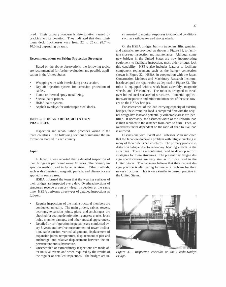
37
INSPECTION AND REHABILITATIONPRACTICES
Inspection and rehabilitation practices varied in thethree countries. The following sections summarize the in-formation learned in each country.
Japan
In Japan, it was reported that a detailed inspection oftheir bridges is performed every 10 years. The primary in-spection method used in Japan is visual. Other methods,such as dye penetrant, magnetic particle, and ultrasonics areapplied in some cases.
HSBA informed the team that the wearing surfaces oftheir bridges are inspected every day. Overhead portions ofstructures receive a cursory visual inspection at the sametime. HSBA performs three types of detailed inspections asfollows:
• Regular inspections of the main structural members areconducted annually. The main girders, cables, towers,bearings, expansion joints, piers, and anchorages arechecked for coating deterioration, concrete cracks, loosebolts, member damage, and other unusual appearances.
• Detailed or configuration inspections are conducted ev-ery 5 years and involve measurement of tower inclina-tion, cable tension, vertical alignment, displacement ofexpansion joints, temperature, displacement of pier andanchorage, and relative displacement between the su-perstructure and substructure.
• Unscheduled or extraordinary inspections are made af-ter unusual events and when required by the results ofthe regular or detailed inspections. The bridges are in-
strumented to monitor responses to abnormal conditionssuch as earthquakes and strong winds.
On the HSBA bridges, built-in travellers, lifts, gantries,and catwalks are provided, as shown in Figure 31, to facili-tate close-up inspection and maintenance. Although somenew bridges in the United States are now incorporatingequipment to facilitate inspection, most older bridges lackthis capability. HSBA also includes features to facilitatecomponent replacement such as the hanger connectionshown in Figure 32. HSBA, in cooperation with the JapanConstruction Methods and Machinery Research Institute,has developed the repair robot as depicted in Figure 33. Therobot is equipped with a work-head assembly, magneticwheels, and TV cameras. The robot is designed to travelover bolted steel surfaces of structures. Potential applica-tions are inspection and minor maintenance of the steel tow-ers on the HSBA bridges.
For assessment of the load-carrying capacity of existingbridges, the current live load is compared first with the origi-nal design live load and potentially vulnerable areas are iden-tified. If necessary, the assumed width of the uniform loadis then reduced to the distance from curb to curb. Then, anoverstress factor dependent on the ratio of dead to live loadis allowed.
Discussions with PWRI and Professor Miki indicatedthat the Japanese do have a problem with fatigue cracking inmany of their older steel structures. The primary problem isdistortion fatigue due to secondary bending effects in thestructures. There is a continuing need to develop retrofitstrategies for these structures. The present day fatigue de-sign specifications are very similar to those used in theUnited States. The Japanese believe that their current de-sign practice is eliminating fatigue as a problem for theirnewer structures. This is very similar to current practice inthe United States.
Figure 31. Inspection catwalks on the Akashi-KaikyoBridge.
used. Their primary concern is deterioration caused bycracking and carbonation. They indicated that their mini-mum deck thicknesses vary from 22 to 25 cm (8.7 to10.0 in.) depending on span.
Recommendations on Bridge Protection Strategies
Based on the above observations, the following topicsare recommended for further evaluation and possible appli-cation in the United States:
• Wrapping wire with interlocking cross section.• Dry air injection system for corrosion protection of
cables.• Flame or thermal spray metallizing.• Special paint primer.• HSBA paint system.• Asphalt overlays for orthotropic steel decks.

38
In the area of rehabilitation, it was learned that tempo-rary post-tensioning has been used on simple span bridgeswhile the deck was removed. Alkali-silica reactivity hasbeen observed in bridge piers that were 15 years old. Thepiers were sealed to prevent moisture ingress. Carbon fibersheets are being used to strengthen bridge decks and piers.
South Korea
Following collapse of the Sung-Su Grand Bridge, a“Special Law on Safety Management of Facilities” waspassed. This law classifies bridge inspections as follows:
• Routine Inspection: four times per year for all bridges.• Annual Inspection: once a year for major bridges. (First
and second class bridges as defined by law.)• Emergency Inspection: as needed following emergen-
cies or natural disasters.• Detailed Inspection: every 5 years for first class bridges
which are at least 10 years old.
The new law requires that inspectors be trained and quali-fied.
KHC currently has the following inspection program:
• Regular Inspection: two times per year.• Inspection of Structures Identified for Observation:
once per month.• Inspection at Any Time: as needed following emergen-
cies or natural disasters.
KHC has 26 bridge inspectors, one in each province,and a 25-person analysis/evaluation group in the main of-fice. Bridge inspection standards are based on the U.S. Na-tional Bridge Inspection Standards (NBIS) and the NationalBridge Inventory (NBI). Equipment used in their inspec-tions includes videocameras, half-cell potentiometers, ultra-sonic testers, and photogrammetry. Special techniques in-clude load tests and modal analysis. Special repairtechniques have included external post-tensioning.
Taiwan
The Taiwan Area National Freeway Bureau inspects itsfreeway bridges twice per year. Inspections are performedby in-house staff who have been trained by consultants.Bridges that are not part of the freeway are inspected every2 years. The inspectors generally use visual observations tocheck deformations of bridge bearings, deformation orsettlement of piers, excessive deflection of superstructures,crack widths, concrete spalling, and rust staining. Equip-ment used for access and non-destructive testing is similarto that used in the United States.
Recommendations on Inspectionand Rehabilitation Practices
Based on the above observations, the following topicsare recommended for further evaluation and possible appli-cation in the United States:
Figure 32. Hangar replacement atachment on the Akashi-Kaikyo Bridge.
Figure 33. Repair robot (Diagram by HSBA).

39
• Greater emphasis on built-in access and utilities forbridge inspection and maintenance.
• A repair robot for use in inaccessible areas.
PROGRAMMING AND MANAGEMENTPRACTICES
Very little was learned about programming and man-agement practices. It seems that practices in the UnitedStates are more advanced than those in the three countries.
Japan
None reported.
South Korea
MOTC has a bridge management system for nationalhighways developed for MS-Windows with a graphic userinterface. The 5 regional construction and management of-fices and 19 highway maintenance and construction officesare connected through a computer network. The bridge man-agement system offers the following features:
• Input/output of various bridge-related data.• Input/output for inquiries about inspection results.• Publication of status of bridges in the country.• A decision-making system.• Calculation of priority for repair, rehabilitation, or re-
placement.• Selection of the method to repair or replace a damaged
bridge.• Calculation of costs for repair, rehabilitation, or replace-
ment.
KHC reported that they have a system for small bridges andwant to develop one for larger bridges. They have studiedPONTIS for possible use as a model.
Taiwan
The Taiwan Area National Freeway Bureau has had abridge management system (BMS) since 1987. This systemincludes the basic inventory and design, construction, in-spection, and maintenance information for the bridges. Thesystem is being replaced with a newly developed BMS thatuses a rating system for bridge defects. A defect in a bridgeis rated for each of the following:
• Degree of severity of the defect.• Extent of the defect over the area of the component.• Importance of the defect on serviceability and safety.
The scoring is used to determine the priority for mainte-nance and budgeting.
OTHER INNOVATIONS
Marketing of U.S. Engineering and Construction Services
In the conduct of this scanning tour, the team met withmembers of the U.S. Commerce Department and other traderepresentatives. Benefits derived from these meetings werevaried. One issue relates to the marketing of U.S. engineer-ing and construction services abroad. The U.S. commercerepresentatives offered an opinion that there was a generallack of interest in their published announcements of oppor-tunities for construction and engineering services. Afterfurther discussion, it became evident that the relationshipbetween the engineering representative organizations andcommerce department officials was minimal or non-exis-tent. The vehicle for announcements of opportunities is theCommerce Department Journal which is not typically readby the engineering community. This is an issue best raisedwith ARTBA, AGC, and ACEC representatives. Certainlythe industry and the commerce department have much togain from improved relationships and better communica-tions.
Visitors’ Centers and Marketing Materials
Many construction sites and private and public officesites had excellent visitors’ centers and excellent informa-tional materials for distribution. The informational materi-als are included in the lists in Appendix B. This practice isin contrast to U.S. practice. Investing in the positive market-ing of engineered products has many tangible and intangiblebenefits. The public is better informed about the impacts tobe expected, work progress, and justification for the project.They are also able to comprehend the positive long-termactions taken by public authorities. Private investments areencouraged to progress in tandem with the public invest-ment. Young people are able to be brought onto active con-struction and manufacturing sites, given broad overviewsinto the technical world, and as a result, the imaginations oftomorrow’s engineers and policy makers are stimulated.Professionals are able to more quickly ascertain the specificsof a project and to determine the technologies and practicesthat are worthy to be taken back to their own offices forimplementation.
Miscellaneous Innovations
The following miscellaneous innovations were alsomentioned during the tour. However, detailed informationwas not provided.

40
• PWRI is developing a scour detection device using theprinciple of a fish finder.
• The Japanese have built two corrugated web platebridges with a wave length of 1.2 m (3.9 ft) and a totalamplitude of 200 to 300 mm (7.9 to 11.8 in.).
• In South Korea, the team learned that steel fiber rein-forcement concrete is being studied as a means to re-duce cracking in concrete bridge decks. Steel fibers areadded at 0.50 percent by volume, but finishing prob-lems have been experienced.
• KHC has used some instrumentation on bridges andseems to make extensive and effective use of intelligenttransportation systems.
• KHC is planning to build a test road with two bridges.The test road will parallel an existing road and use regu-lar highway traffic.
Recommendations on Other Innovations
Based on the above observations, it is recommendedthat greater emphasis be placed on public relations programsfor major projects.
APPENDIX A AMPLIFYING QUESTIONS
1. INTRODUCTORY TOPICS
1.1 What is the organizational arrangement for bridge own-ership, design, construction, maintenance, and funding?
1.2 What are the current major issues related to funding,design, construction, and maintenance?
1.3 What is your relative market share of steel versus con-crete bridges. What controls this market share?
1.4 How do you decide where and when to build newbridges?
2. DESIGN STANDARDS, CODES ANDSPECIFICATIONS
2.1 How are bridge design standards, codes, and specifica-tions developed, implemented, and updated?
2.2 What design approach is currently used (service load,load factor, load resistance factor, limit state, or other)?What changes do you anticipate in the future?
2.3 What are the design provisions for vehicular load, over-loads, earthquake, ship impact, thermal gradient, loadcombinations, scour, bridge deck replacement, environ-ment requirements, aesthetics, and redundancy withfracture critical members?
2.4 To what extent are performance specifications used?
3. DESIGN AND CONSTRUCTION
3.1 What types of bridges, foundations, and constructionmethods are used? How are they selected?
3.2 To what extent is design automated and how is thisimplemented?
3.3 To what extent is design-build or design-build-oper-ate used? What types of specifications are used? Whatare the results?
3.4 Do you consider user costs and public inconveniencein design and construction? If so, how?
3.5 Are alternate designs prepared and can contractorssubmit alternate designs?
3.6 What aspects of design and construction are standard-ized?
3.7 How is the intent of a design implemented in the con-struction process?
3.8 How are designers and contractors selected and paid?What incentives or penalties are provided to designersand contractors?
3.9 How much are innovation, prefabrication, and auto-mation used in construction?
3.10 How are quality control and quality assurance of ma-terials and construction processes implemented? Arein-place instrumentation systems used?
3.11 What warranties or guarantees are provided for mate-rials and completed construction?
4. FABRICATION AND JOININGTECHNIQUES
4.1 How closely do designers, steel producers, and steelfabricators work together?
4.2 What recent developments in materials technology andcutting or drilling techniques have made your plate steelmanufacturing processes successful?
4.3 What is your experience with corrosion resistant weath-ering steels and galvanized, metalized, or coated bridgesteels?
4.4 What is your experience with fatigue and fracture ofstructural steels? What conclusions have you drawnfrom your experience?
4.5 How do you combine ease of erection and joining withthe steel fabrication process?
4.6 What is current state of knowledge and practice regard-ing cable design, fabrication, erection, inspection, andcorrosion protection?
4.7 What prestressing systems, strand sizes, corrosion pro-tection systems for post tensioning, types of precast con-crete joints, and external post-tensioning systems areyou using? What has been your experience?
4.8 What types of bridge bearings, deck joints, and deckdrainage systems are used?

41
5. BRIDGE DECK PROTECTION STRATEGIES
5.1 What types of bridge decks are used? What is the per-centage of each?
5.2 What are the primary types and causes of bridge deckdeterioration?
5.3 What are your bridge deck protection strategies, howare they chosen, and what is done to promote durabil-ity? How do different strategies compare in terms ofimplementation, performance, and cost.
5.4 What is the design life, expected life, and actual life ofyour bridge decks?
5.5 How is in-service bridge deck performance evaluated?
6. INSPECTION AND REHABILITATION
6.1 What types of formal bridge inspection programs are used?6.2 How is the program implemented in terms of responsi-
bility, staffing, training, qualifications of inspectors,data collection, quality control, inspection frequency,detail of inspection, and application of results?
6.3 How do you assess vulnerability of existing bridges tofailure from earthquakes, scour, overload, vehicle andship collision, steel details, and concrete details?
6.4 What tools and techniques are used to identify chloridepenetration in concrete; corrosion and fatigue of struc-tural steel, nonprestressed reinforcement, prestressingsteel and stay cables; and scour?
6.5 What types of equipment are used for access, visualinspection in inaccessible areas, non-destructive test-ing, underwater inspection, and automated inspection(cameras, instrumentation, computers, fiber optics, androbotics)?
6.6 What means and methods are used to determine loadcarrying capacity of existing bridges?
7. PROGRAMMING AND MANAGEMENT
7.1 Do you have an established database of bridge type andcondition?
7.2 What information do you collect and how is it used tomanage bridges and set priorities for maintenance, im-provements, and replacements of existing bridges?
7.3 How do you include information from bridge inspec-tions and bridge maintenance programs into financialdecisions and design standards and codes?
7.4 How do you decide whether to rehabilitate or replace abridge or bridge deck?
7.5 What techniques are used in bridge rehabilitation forremoval of existing materials, increasing load capacity,quality control and assurance, retrofitting of fatigue-sensitive details, treatment of lead-based paints, repairof scour, rapid bridge deck replacement, and replace-ment of welding with adhesives?
8. INNOVATION
8.1 What significant investments and advancements havebeen made in the last ten years to enhance the bridgedesign and construction industries?
8.2 How are innovative materials (high-strength steel, high-performance concrete, lightweight concrete, fiber-rein-forced composite materials, fiber-reinforced concrete,high performance coatings, and geo-synthetics) intro-duced and used in bridge projects? Who promotes thedevelopment and utilization and who accepts responsi-bility?
8.3 To what extent are innovative materials being used toprovide higher strength and improved durability?
8.4 How is quality control and performance of innovativematerials and methods monitored? Are in-place instru-mentation systems used?
8.5 What research do you recommend for safer, more du-rable bridges?
8.6 What recent experience, research, and retrofit has therebeen for cable-stay vibrations caused by wind andrain?
APPENDIX B MATERIAL REVIEWED
This appendix contains a list of documents that were used inthe preparation of this report.
JAPAN
Honshu-Shikoku Bridge Authority
Honshu-Shikoku BridgesAkashi-Kaikyo Bridge Engineering NoteAkashi-Kaikyo BridgeSeto-Ohashi Bridges, Kojima-Sakaide Route in Honshu-
Shikoku BridgesSeto-Ohashi BridgeHonshu-Shikoku Bridges, Kojima-Sakaide RouteDesign of Shock-Absorbing Device of Akashi-Kaikyo
Bridge for Ship CollisionNishiseto Expressway (Onomichi-Imabari Route)Nishiseto Expressway, Kurushima BridgesKurushima Bridges-Cable WorksTatara BridgeBoundary Layer Wind Tunnel LaboratoryRepair Robot (for High-Rise Structures)Synonymous with Long-Span Bridge TechnologyTanaka, K., Sato, K., Watanabe, S., Arima, I., and Suenaga,
K., “Development and Utilization of High PerformanceConcrete for the Construction of the Akashi-KaikyoBridge,” High Performance Concrete in Severe Environ-ments, Publication SP-140, American Concrete Institute,Detroit, 1993, pp 25-51.

42
Japan Highway Public Corporation
National Expressway Practices in JapanDevelopment of Technology for Expressway Bridges
Metropolitan Expressway Public Corporation
Metropolitan Expressway 1996
Nippon Steel Corporation
Nippon Steel Kimitsu WorksJapan’s Steel Industry and Kimitsu WorksNippon Steel, Research & Engineering CenterHigh Performance Steel in Japan, Presentation for FHWA,
September 18, 1997Miki, C. and Homma, Koji, “Application of High Perfor-
mance Steels in Bridge Structure.”Corrosion Protection System for Cables
Yokogawa Bridge Corporation
Yokogawa Steel Bridges & FramesComputerized Assembly and Testing System (CATS)Torii, K., Kojakura, Y., and Takada, K., “Computerized As-
sembling Test System for Steel Bridges: CATS.”Challenges to Civil and Mechanical Engineering in 2000
and Beyond, Conference June 2-5 1997, Wroclaw, Poland
Sumitomo Metal Industries, Ltd.
Weather-Act Method
SOUTH KOREA
Ministry of Construction and Transportation
Roads in Korea
Korea Highway Corporation
Korea Highway CorporationHighway Research CenterSeo-Hae Grand Bridge
Ssang Yong Engineering & Construction Co., Ltd.
Kimp’o Grand Bridge
TAIWAN
Taiwan Area National Freeway Bureau
Annual Report 1996Taiwan Area National Expressway Engineering Bureau In-
troductionHsichih-Wuku Viaducts Widening Project, Sun Yat-Sen
FreewayImages of the Northern Taiwan Second FreewayFreeway Traffic Surveillance & Control System
APPENDIX C ITINERARY
Japan
September 14, 1997. Team Review MeetingSeptember 15, 1997. Meeting with Honshu-Shikoku
Bridge AuthoritySeptember 16, 1997. Site Visits to Akashi-Kaikyo
Bridge and Kojima-SakaideRoute
September 17, 1997. Site Visits to Kurushima andTatara Bridges
September 18, 1997. Nippon Steel CorporationSeptember 18, 1997. Yokogawa Bridge CorporationSeptember 19, 1997. Meeting with Public Works
Research Institute, JapanHighway Public Corporation,and Metropolitan ExpresswayPublic Corporation
South Korea
September 21, 1997. Team Review MeetingSeptember 22, 1997. Meeting with Korea Highway
CorporationSeptember 22, 1997. Site Visit to Seo-Hae Grand
BridgeSeptember 23, 1997. Site Visit to Kimp’o Grand
Bridge and Youngjong BridgeSeptember 23, 1997. Meeting with POSCO Manufac-
turing Corporation
Taiwan
September 25, 1997. Site Visit to KaohsiungBeltway, Chishan Branch, andKao-Ping Bridge
September 26, 1997. Meeting with Taiwan AreaNational Expressway Engineer-ing Bureau
43
September 26, 1997. Site Visit to Hsichih-WukuViaducts and Traffic Surveil-lance and Control Center
September 27, 1997. Team Review Meeting
APPENDIX D TEAM MEMBERS
The team consisted of representatives from U.S. federal,state, and private sector agencies. This appendix containsbrief biographical information about each team member.
Mr. Charles (Chuck) L. Chambers, Team Co-Chairman,is a Senior Structural Engineer in the Office of Engineer-ing, Bridge Division, FHWA, Washington, DC.
Mr. James E. Siebels, Team Co-Chairman, is the ChiefEngineer for Design and Construction for the ColoradoDOT located in Denver, Colorado.
Mr. Ralph E. Anderson is the Bureau Chief of Bridges andStructures for the Illinois DOT in Springfield, Illinois.
Mr. John P. Formosa is the Division Bridge Engineer forthe New York Division of the FHWA in Albany, NewYork.
Mr. John M. Hooks is the team leader for the StructuresApplications Team, Office of Technology Applications,FHWA in Washington, DC.
Dr. John M. Kulicki is President and Chief Engineer ofModjeski and Masters, Inc., of Harrisburg, Pennsylvania.
Mr. Jerry L. Potter is the State Structures Design Engineerfor the Florida DOT in Tallahassee, Florida.
Dr. Henry G. Russell is an engineering consultant whospecializes in concrete design, construction and research.
Mr. James E. Sothen is Director of Structures Division forthe West Virginia Division of Highways located inCharleston, West Virginia.
Mr. William J. Wright is a research structural engineer inthe Structures Division of the FHWA’s Office of Engi-neering Research and Development, where he has workedfor the last 8 years.
Mr. George Y. Yamamoto is a registered civil engineerworking for the California DOT.
APPENDIX E ACRONYMS
Japanese Organizations
HSBA Honshu-Shikoku Bridge AuthorityJH Japan Highway Public CorporationJSCE Japan Society of Civil EngineersJIS Japanese Industrial StandardsMEPC Metropolitan Expressway Public CorporationPWRI Public Works Research Institute
Korean Organizations
BPR Bureau of Public RoadsMOCT Ministry of Construction and TransportationKHC Korea Highway Corporation
Taiwanese Organizations
MOTC Ministry of Transportation and Communication
U.S. Organizations
AAR Association of American RailroadsAASHTO American Association of State Highway and
Transportation OfficialsACEC American Consulting Engineers CouncilAGC Associated General ContractorsAISC American Institute of Steel ConstructionAISI American Iron and Steel InstituteARTBA American Road and Transportation Builders’
AssociationASBI American Segmental Bridge InstituteASTM American Society for Testing and MaterialsDOT Department of TransportationFHWA Federal Highway AdministrationFRA Federal Railroad AdministrationNCHRP National Cooperative Highway Research
ProgramNSBA National Steel Bridge AllianceNSF National Science FoundationPCA Portland Cement AssociationPCI Precast/Prestressed Concrete InstituteTRB Transportation Research Board
General Terminology
BMS Bridge management systemCADD Computer-aided design and draftingCAM Computer-aided manufacturingCATS Computerized assembly and testing systemGMAW Gas-metal-arc-weldingHPS High-performance steelsHSLA High-strength, low alloyLRFD Load and Resistance Factor DesignNBIS National Bridge Inspection StandardsNBI National Bridge InventoryNT$ New Taiwan dollarsSAW Submerged arc weldingSI International system of unitsTMCP Thermo-mechanical control processing

44
APPENDIX F SELECTED FIGURE FROM CATSBROCHURE

45
Acknowledgments
The review team wishes to thank the hosting organiza-tions and their staff in Japan, South Korea, and Taiwan fortheir gracious hospitality and for sharing their experienceand time with the team members. In particular, the scanningteam acknowledges the cooperation and assistance providedin Japan by Mr. Shoichi Saeki, Dr. Satoshi Kashima, Mr.Akira Mori, Mr. Yasuhito Kanisawa, Mr. Kunihisa Mori,Dr. Haruki Akiyama, Dr. Masahiko Yasuda, and Mr.Kazuyoshi Sakai of the Honshu-Shikoku Bridge Authority;Mr. M. Ohji, Mr. T. Nishi, Dr. Yukihiko Sumiyoshi, Mr.Shigenori Tsuru, Mr. Hachiro Sakata, Mr. K. Nishioka, Mr.Y. Yoshida, and Dr. Koji Homma of Nippon Steel Corpora-tion; Mr. Kazuhiro Nishikawa of Public Works ResearchInstitute; Professor Chitoshi Miki of the Tokyo Institute ofTechnology; Mr. Masatsugu Fukuda, Mr. NobuyoshiShibata, Mr. Yoshihito Kohata, Mr. Tohru Natori, and Mr.Akio Shirozu of Yokogawa Bridge Corporation; Mr.Hiroyuki Ikeda and Mr. Atsushi Homma of Japan HighwayPublic Corporation; and Mr. Jun Yamada and Mr. KazuhiroTsuno of Metropolitan Expressway Public Corporation. InSouth Korea, the team acknowledges Mr. In-Hee Nam of
the Ministry of Construction and Transportation and Mr.Jung-Tae Park, Dr. Sung Kon Kim, Mr. Jae-Shik Choi, Mr.Kyo Seo Wong, Mr. Sung Soon Ahn, and Mr. Woon-PhilChung of Korea Highway Corporation. In Taiwan, the teamacknowledges Dr. Wen-Lon Cheng, Mr. Nuan-Hsuan Ho,Mr. Song-Maw Hong, Mr. Wen-Chih Fang, and Mr. ChunYat Hsu of the Ministry of Transportation and Communica-tions.
The team members thank the sponsoring organizationsfor providing the opportunity to participate in this review.The NCHRP program officer was Edward T. Harrigan. Priorto the trip, input was provided by James D. Cooper of FHWA,Arun Shirole of the National Steel Bridge Alliance, and ManChung Tang of DRC Consultants, Inc. The visit in Japan wasgreatly facilitated by previous relationships established byJames D. Cooper of FHWA. The sponsors also thank Ameri-can Trade Initiatives, Inc., for organizing the tour, providingthe travel arrangements, and coordinating other activities. Inparticular, the services of Alexandra Doumani, Joseph N.Conn, and John O’Neill are appreciated.
Photographs and figures for the report were providedby the hosting organizations and team members. Their will-ingness to contribute to the report is acknowledged.

46