national aeronautics and space administration general icd information for sdrs for consideration...
TRANSCRIPT

National Aeronautics and Space Administration
www.nasa.gov
General ICD information for SDRsFor consideration for EDS Development
Sandra JohnsonNASA Glenn Research Center, Cleveland, Ohio
CCSDS Spring SOIS/APPS Working GroupApril 2013

National Aeronautics and Space Administration
www.nasa.gov
Scope/Purpose of PresentationUniqueness for SDRs
2
• Introduce the Space Communication and Navigation (SCaN) Testbed
• Describe the approach used by the SDRs to interface with Avionics (OBC)
• Smart device – processor within SDR – may be as capable as OBC
• EDS would reduce effort to integrate different vendor’s EDS and upgrade system to incorporate new waveforms / applications on the SDR
• Configuration files used to enable flexibility

National Aeronautics and Space Administration
www.nasa.gov 3
SCAN Testbed Mission Research & Technology Objectives
• Develop SDR platform hardware & waveform firmware/software compliant to STRS to TRL-7– Promote development and Agency-wide adoption of
NASA’s SDR Standard, STRS– Flight-like ground EM and other equipment to enable the
development, integration and operations of new SDR software on ISS.
• Validate Future Mission Capabilities– Capability representative of future missions (S, Ka, GPS)– Communication, navigation, networking experiments
SCAN Testbed
• Investigate the application of SDRs to NASA Missions– Mission advantages and unique development/verification/operations aspects– SDR reconfiguration, on-orbit reliability
Launched to ISS on JAXA’s H-II Transfer Vehicle (HTV3) on July 20, 2012

National Aeronautics and Space Administration
www.nasa.gov
General Dynamics• TDRSS S-band
(Tx & Rx)• 1 - Virtex II Qpro
FPGA, 3 M gate• ColdFire microprocessor w/ VxWorks
RTOS• CRAM (Chalcogenide RAM) (4 Mb)STRS• Advance STRS/SDR Platforms to TRL-7• Single standard on SDR and WF
• Compliance verified w/
-tools-inspection-observation
SCaN Testbed SDR Platform DescriptionsHarris• TDRSS Ka-band (Tx &
Rx)• 4 - Virtex IV FPGAs• 1 - GFLOP DSP• AiTech 950 with VxWorks RTOS• Scrubbing ASIC
JPL/L-3 CE• L-band receive (GPS)• TDRSS S-band • 2- Virtex II FPGA
(3 M gates each)• Actel RTAX 2000 • Actel AT697 with SPARC V8 Processor
using RTEMs OS
All SDR tested and flown with TDRSS-compliant waveforms.

National Aeronautics and Space Administration
www.nasa.gov
SCaN Testbed Flight System Connections

National Aeronautics and Space Administration
www.nasa.gov
SOIS Architecture – application to SDRs
6
Radios may make use of all services from Avionics.

National Aeronautics and Space Administration
www.nasa.gov
What is implemented in an SDR?
7
Figure from CCSDS 130.0-G-2 “Overview of Space Communications Protocols
Many experiments demonstrate capabilities across most layers
• Software Defined Radios may implement all layers of the CCSDS stack• Boundary between OBC functions and Transceiver function may change depending on system
National Aeronautics and Space Administration
www.nasa.gov
Process to Date
8
• Reviewed 3 SDR ICDs and developed table with generic ICD type information
• Captured information that might be unique for SDR (vs. hardware SDR)
National Aeronautics and Space Administration
www.nasa.gov
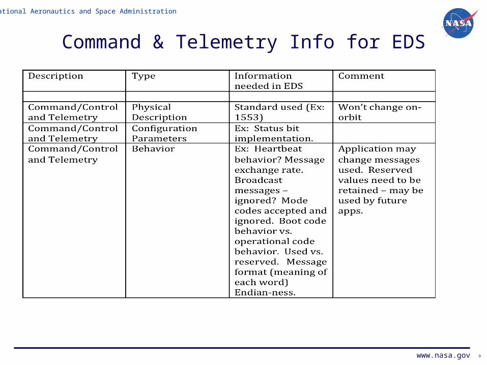
Command & Telemetry Info for EDS
9

National Aeronautics and Space Administration
www.nasa.gov 10

National Aeronautics and Space Administration
www.nasa.gov 11

National Aeronautics and Space Administration
www.nasa.gov 12

National Aeronautics and Space Administration
www.nasa.gov
Typical Telemetry information
13
1. Status (On/Off for controllable component, State (test, idle, running))
2. Software & Firmware version information3. Results of startup tests4. Fault Diagnostic information (number of entries in logs)5. Memory statistics6. Configurable parameters for waveform (data rate, coding
on/off, frequency selected, etc.)7. Waveform status (Carrier lock, etc.)8. Performance (SNR estimate, frame loss, etc.)
Items 6-8 likely to be waveform dependent.

National Aeronautics and Space Administration
www.nasa.gov
Path Forward
14
• For consideration:• Continue to gather ICD-type info for SDR• Design an EDS for an SDR• Implement EDS for an SDR
• Start with hardware (dumb) transceiver?• Support dependent on schedule and availability of
Avionics programmer