national advisory committee ' l for aeronautics/67531/metadc55773/m2/1/high... · national...
TRANSCRIPT

NATIONAL ADVISORY COMMITTEE ' L FOR AERONAUTICS
TECHNICAL NOTE No. 1662
AERODYNAMIC PROPERTIES OF SLENDER WING-BODY
COMBINATIONS AT SUBSONIC, TRANSONIC, .
AND SUPERSONIC SPEEDS
By John R. Spreiter
Ames Aeronautical Laboratory Moffett Field, Galif.
July 1948 ,
. .
.

TECFAEAL NOTE: No. 16Q
COMBIXATTONS ATSUBSORE, TRNFSORIC,
AND -oNIc! SW
By John R. Spreiter
A method based on assumptions similar to those of Munk's airship theory end R.T. Jones ' lowdspect-ratio pointed-wing theory has been developed to determine simple closed expressions for the load distribution, lift, pitching moment, and center-of- pressure position of inclined slender wing+ody configurations having flat-plate wings extending along the continuation of the horizontal diameters of circular fuselage sections. Expressions for the aerodynemic properties of triangular wings in combination with conical bodies, semi-infinite cylindrical bodies, and bodies pointed at the nose but cylindrical at the wing root have been developed in detail for all ratios of body diameter towing span. In all cases, the lift-curve slope of the wing-body combination was less than that of the wing alone. For the case of the triangular wing end the body pointed at the nose but cylindrical at the wing root, the loss in lift-curve slope reached a maximum of 25 percent at.the large diemete~pan ratio of 0.707. With a conical body mounted on the same wing, the maximum loss of lift-curve slope was only about 8 percent and occurred at about the seme diameter-span ratio.
It is shown that the results are applicable at subsonic end tiensonic speeds, and at supersonic speeds, provided the entire winghody combination lies near the center of the Mach cone. Furthermore, It is pointed out that the assumptions related to the study of low~spect-ratio pointedbodies and the study of moderate- aspect-ratio pointed bodies traveling at sonic speed both lead frcan Prandtl's linearized equation for compressible flow to the tw+ dimensional Laplace's equation in the transverse plene although by different means.
2 r NACA TN No. 1662 I
The determination of the potential distribution for an inclined moderat-spectiatio wing at sonic speed is therefore mathematically equivalent to the determination of the poteritial distribution for an inclined lo-spect-ratio wing in.an incompressible fluid.
INTRomcTIoN
In the quest for airplane configurations having aerodynamic . properties favorable for supersonic flight, one of the more promising configurations involves the use of a low-aepect-ratio wing. When the general layout of such an airplane is considered, however, comparatively large fuselages are often found necessary. It thus becomes important to study the aerodynemice of a complete wing- body cabinatian throu&out the entire Mach number range of the air- plane. In an incompressible medium, the mutual interference of-a fuselage and wing of high-aspect ratio (to which liftineline theory is applicable) has been treated by Lennertz, Wieselsberger, Pepper, and Multhopp.in references 1, 2, 3, and 4. It is the purpose of this note to treat the effect on the aerodynamic loading of the mutual interference between a low-aspect-ratio pointed wing and a fuselage consisting of a slender body of revolution.
Yhe aerodynemic properties of slender win@ody configurations may be approximated by the method originally used by Munk in studying the aerodynamics of slender airships (reference 5). R. T. Jones (reference 6) applied this method to the study of low-spect-ratio pointed wings and Ribner (reference 7) extended it to determine the stability derivatives of low+specl+ratio triangular wings. The essential point in the study of slender bodies by this method is the fact that the flow is approximately twoitimensional when viewed in planes perpendiculer to the direction of motion. Methods of classical hydrodynamics may then be employed to determine the load distribution, lift, end center of pressure.
It has been shown by Tsien, Laitone, and R. T. Jones (references 8, 9, and 6) that the aerodynamic properties of very slender bodies of revolution and lowespect-ratio wings at small angles of attack are unaffected by coropressibility at subsonic and supersonic speeds. A similar result will be shown for slender wing4od.y combinations.
SYMBOLS
A aspect ratio.( !+)
mCi TN No. 16Q 3
B
%
4tl
CL
Qw
Cm
cW
L
M
M,
S
U
W
X
a
C
01
d
2
m
cross-section area of body of revolution (na2>
cross-section srea of base of body of revolution
mean cross section of body of revolution
lift coefficient L 0 qs
lift-curve slope ( >
GEL da
lift coefficient of ting without body
pitching moment coefficient M ( > qsc pitching moment coefficient of wing without body
lift
pitchingm~nt about apex of wing
free-stream Mach number
wfng area
velocity of flight
complex potential function (q-k I*)
complex variable (y + 155)
radius of body
maximum wing chord
distance from apex to section of maximum span
semispan of flat plate
over-eJl length of wir@~ody combination
additional apparent mass of circular cylinder

4
P
9
MJ
6
t
v,w
X,Y,Z
xc.p.
cp
*
a
a
rllr;
5
P
static pressure
free-stream dynamic pressure
polar coordinates
local semispan
maximum semispan
tw
velocities in y and z directions
cartesian cocrdina~s
distance from apex to center af pressure
velocity potential
streamfunction
angle of attack
downwash angle
transformed rectangular coordinates
complex variable (q+i!,)
density of air
Subscripts
W wa3
F boas
C comgressible
I incompressible .
mAca TN No. 1662 .
.
.

NACA TN No. 1662 ‘
5
General
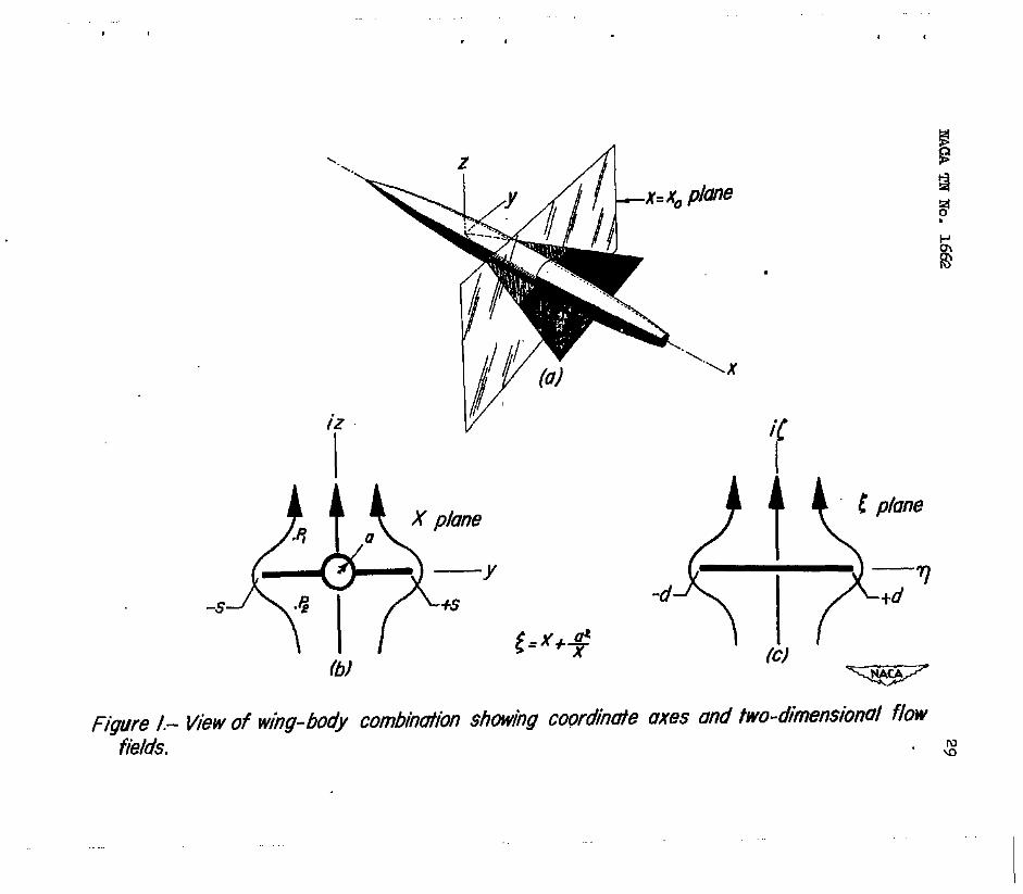
The flow around an inclined win@ody combination of very low aspect ratio maybe approximated by considering it to be two dimensional in trensverse planes (perpendicular to the fuselage center line). It can be shown as a consequence of this assumption that the flow in each transverse plane is independent of f&at in the adjacent planes. Consider a coordinate systemmoving downward through the air with a velocity Ua. The wineody ccmbinationis now considered to be flying in the negative x-dire&Ian with a velocity U and angle of attack a so that the fuselage center line coincides with the xexis of the coordinate system and the plane of the wing coincides with the 2 = 0 plane. (See fig. l(a).) The flow pattern, then, in the arbitrary x = ~0 plane during the time of the passage of the wing-body combination is approximately similar to that of the transverse flow around en infinite cylinder having a cross section similar to the local wing&ody section. Observed in this plane, the semispan of the wing and the radius of the fuselage change with time as the wing41ody combination moves through the plane. The resulting unsteady nature of the flow pattern produces pressure differences betweencorresponding points on the upper and
* lower surfaces of the ting and fuselage. The following analysis, therefore, consists of three parts: determination of the velocity potential for the two-dimensional flow'around the wing-body sections,
. determination of the distribution of load over each section, and integration of the loading to determine the total lift and pitching . moment. Several examples ere included presenting the total lift, center of pressure, and load distribution for typical complete wing- body configurations.
Velocity Potential
It is necessary for the .subsequent analysis to lmow the velocity potential for the unsteady two-dimensional transverse flow field around en infinite cylinder,the cross section of which is varying with time in such a manner that it always remains similar to the wing+ody section in the x=x, plane. Due to the infinite rate of pressure propagation in an incompressible fluid, the study of the unsteady flow of an incompressible fluid is greatly simplified since the flow field at any instent is identical to that of the corresponding steady+tate flow. The first step in the solution of the present problem, therefore, is to determine the velocity potential for the steady-state flow around an infinite cylinder having a cross section similar to the wing-body section. El this enalysis, only wing+ody

6 NACA TN No. 1.662
ccmfigurations having circular fuselage sections andfla-late wings extending along the extension of a diameter will be treated. Ihe flow around such a section may be obtained from the transverse flow around an infinitely long flat plate by applicatiw of the principles of conformal mapping using the Joukowski transformation. Thuawe consider the mapping shcwn in figure linwhich the 5 plane will be mapped onto the X plane by the relation
where
and
X = y+iz
!Lhe ccmtplex potential fmcticn for the flow in the 5 plane is ( see, for instance, reference 10)
W' = (p' + ilp = -1lJa J-&Z (2)
where the primed symbols indioate values in the 5 plane as opposed to theX plane. It is also shown in reference 10 that, if d=2a, the flow around a flat plate expressed by equation (2) transforms by equation (1) intd the vertical flow around a oircle of radius a having its center at the origin. If d is taken larger than 2a, the flat- plate flow transforms into the desired vertical flow around a cylinder consisting of a uiroular cylinder of radius a with thin flat plates extending outward along the extension of the horizontal diemeter to a distance a from the origin. When the 5 plane is transformed into the X plane in this manner, the complex potential for the flow in the X plane is found to be
eince the pointd in the f plane correspmdsto the points in the xplane. The velocity potential cp for the flow in the X plane may

I
I . . .
then be found by squaring equation (3), mbetitutlng X = r (COB ~9 + i. ain e), and solving. !mlalsollt!ilned
- (lt$)r%oa 2&s 2 (l-t$) ] + jr{ 15) +2a%os 49+a4 (19 )L (19) (li$) r2cos 20
(4)
prhere i%e slep Is poeitlve ln the upper half plane (O<e<*) and ne@lve ln the lowsr half plam (rt<8<2x).
Load Dlstzlbutlon
Once the velocity potential of a flow field la known, the methods of cLm3loal hydrc- dynamicsmaybe applied to detamin.3 the presmre atanygolnt ln the field. Oomlder a&n, the cme shorn in flgmm lwhere the Kingbody cmublnatlonls~lerclng the x=x. plane. AE prevloueLlynot~d,tbe flow in the x=x.,, plane la comlderedtobe similar to the tuo- dimensional flow sorrouudlngan lnfinlt3lylongoyllnderhavingthe shape of tJm tigybody crow section intemectedbgthe mxoplane. Iftberadlwoftbebody a'endthemmlepan of the Hng a are consideredto be functions of tlme,equatlon(4)maybe thought of YES representlngtbe vt3locltypotentlal of t&e unsteady flow in l&e x=x. plane, In the cam ofunsteady izm-dhensld potential flow of an lncanpreselble fluid, the pressure at any point fixed ln the ooordlnate system la given by (EW, for k&awe, reference XL, p. 19)
It w be seen tkt this expression reduces to the well-known Bernoull~s equation for the preaswe in a stemQ flow field when the velocity potential IB lnvarlmt with time
and the arblt& function of time F(t) le a constant. 2-O
(5)

, 8 r?AcA TN No. 1662
For any two corresponding points P1 and P2 (fig. l(b)), so selected that- yl = y2 and z1 = -z2, the differential preseure at any Instant ie given by
4 P=+ ag2 a(k 1 - = -- = at P P
- - + - - 2 (v&w29 at
+ ; (vp+wp)
= + 2 ~ - 1 (vg%w2”) + IL at 2 r?' v12+Q2) (6)
EKLIlCe acp2 acpl
-at=at by reason of symuetry of the flow field. Now if
the point8 are brought to tie an&body surface
v22+w22 = v12uw12 the differential pressure between any two corresponding pointe (or the loading) is given by
4 3% -=++2 P
(7)
Utilizing the relationship
acpl -= at
and dividing equation (7) by $U2, the loading coefficient is found to be
ia(p1
> (9)
!JBe load distribution may now be obtained by substituting the expression for the velocity potential given in equation (4) into equation (9) and letting 800 or 0=x for the wing loatig end r=a for the fuselage loading. The-loading over the wing is then found to be gfven by

NACA TN No. 1662
and that over the fuselage is given by
9
1 (10)
() I 4, =: Z.l- .TF
( 3 +q23-$-cos263
/(i +$) -2 g COB 20 4
(11)
I 4 k /
Ia Cartesian coordinates,the loadlng over the fuselage is
cx. T- =4c
J
0-Q) 1 TotalLiftandmnt
Theto~llftandpitchingmosnentof acrxqletewing-body ccanbination may be determined by intewating the loading over the entire plan-form axea. It is convenient to caxry out the integra- . tionbyfirstevaluat~ the lift on one spanwise strip and then integrating these elemental lift forces over-the length of the wing- , body cwnbination. 'Ihe lift on a spanwiee strip of width dx is given by
a=2q69[ $9(:x asin d9 +[ ($k dr] (13)
or, in Cartesian coordinate6
(14)

10 NhCA TN No. 1662
When the indicated operations are performed, the following expree8Fon.B for the elemental lift-on.-the wing and body are obtained.
Noting that
(16)
equations (15a) and (1%) may be combined and simplified-to give the following expression for the total lift on ag qlemsn&al spanwise strip.
.
I
.
.

NACA TN No. 1662
l%e lift, pitching moment, and center pf pressure of the complete wing-body ccmbinationmay nowbe detexminedby integration of the lift of all the elemental strips
L=qf&@ti
X a c.p. =-L
m
(20)
11
where the integration interval extends fram the most forward point to the most re ezwardpointof the win@odyconfiguration. The lift coefficient, moment coefficient, and center of preesure may be determined from equations (x8), (19), akd (20) by division by appropriate constants
xC.p. cm -z-b C %
(22)
(23)
where S is the reference area end c the reference chord or length.

12 NhCA TN No. 1662
Effect of Compressibility
In contrast to the well-known infinite~spect-ratio case where the pressures on the surface of awing are influencedby compressi- bility in a manner described by the Prmdtl-Glaue,-t relation, it has been shown by several investigators that the pressures on very low- aspectrratio wings and very slender bodies of revolution 8;ce unaffected by CcmrpmSSibility. This result has been found.by Jones (reference 6).for low-aspeot-ratio
9 ointed wings at both subsonic
and supersonic speeds. B. G&hert reference 12) extended the low- aspectiatid rectangular wing theory of Bollay (references 13 and 14) to include the influence of cmpressibility and found no effect in the subsonic range. For a very slender inclinedbody of revolution at subsonic and superscmic speeds, Laitone and Tsien (references 9 and 8) have found that the loading was unaffected by compressibility. That such is also the case for slender inclined, pointed win&body combinations follows frcm cmsideratim of the basic differential equation of linearized cmnpressible flow. In addition, It will be shown that the aspect-ratio range to which the theory Is applloable becomes tiger as the Maoh number approaches one.
Prsndtl (reference 15) has found the linearized differential equation for the velocity potential of'ccmpressible flow to be
Ta the development of the expressions for the forces on long slender a2cp wh@tody cm.fibfnationa, It has been assumed that m is so mmh
smaller than 3 and T as2
that the first term of equation (24) 2
may be neglected. Therefore, solongas the tem(l-Mo2)~
in the differentialequatimremains small,Machnunibertillhave little influence on the distribution of the velocity potential. Consequently, Maoh nmiber has little effect on the aerodynamic characteristics of a long slender win&~ody ccmbination at either subsonio or supersonic speeds. It is immediatelyappazentthat the Mach number cannot be increased indefinitely, for then the coeffi-
a% cientof - ax2 becamss so large that the first term will no lmger I

. NACATNNo. 1fXQ 13
be negligible. The required condition will be, satisfied, however, if the body has a pointednose, the wingapointedplanform, end the entire ting-body combination lies neer.the center of the Mach cone. All these conditions, however, correspond to those originally assumed In the derivation of the expression for the velocity potential (equation (4)). Therefore, the present theory is applicable at supersonic speeds, as well as subsonic speeds, provided the entire win&ody combination lies near the oenter of the Mach cone.
It has been shown by Robinson and Young (reference 16) that, for finite aspect ratio, the linearized theory of compressible flow (equation (24)) remains theoretically consistent and yields finite and continuous lift-curve slopes in the transonic range. Recent experiments on trfangular wings at transonic speeds support this contentfon by indicating agreement between measured and computed lift-curve slopes. merefore, to predict the flow around a body traveling at or very near sonic velocity, it is correct, unless the
term 3 ax2
becomes extremely Large, to let Mo=l and solye the
remaining equation for the potential distribution. The remaining equation is the two-dimensional Laplace's equation in the transverse plane. This means that, althou& the veloc-ity potential may vary in the longituddnal direction, ite value at each point may be determined solely by studying the flow in the transverse plane containing the point in question. merefore, since thfs fs precisely the manner in which the potential distribution was obtained, the results of the present analysis are applicable at transonic speeds. In fact, the present theory is most applicable to wing-body ccmbinations of .moderate aspect ratio if the Mach number is one,since
it is then no longer necessary to assume that a2q - is very much
c9, and cq ax2 smaller than .
w a22 J.n retrospect,the assumptions related to the study of low+mpect-
ratio pointed bodies and the study of moderate-aspect-ratio pointed bodies travelin
'f at sonic speed both lead from the Rrandtl equa-
tion (equation 24)) to the twc+dImensional Laplace's equation in the transverse~plane although by different means, The low-aspect-
ratio theory neglects the term (1-Mo2) $ a29 inccanparisontith - w
and B because a29 \ a22
- is very small; while the moderate-aspect- ax2 ratio sonic theory neglects the same term because (l-Mo2) is zero.

14 RACA TR No. 1662
Thus the d&ermination of the potential distribution for an inoldned mderate+spe,otiatio wFng at the speed of sound is mathematically equivalent to the detmmination of the potential distribution of an inolined low-speckratio wing in an incompressible fluid.
For a givenwing-body oonfigurationccu@yingtith the general requirements of the present theory, the load distributim may be determined dlreotly by substituting the proper values for the body radius andwing semispanandtheirrate of ohenge w'ith x into equations (10) end (11). In addition, closed expressions for the lift, pftching mment, and oentee-gressure position of several elementa;ryconflguratlansmay~adilybefoundbys~le integration of the integrals lndioaked by equatimm (2l), (22), and (23). Several such examples will be presented in detail 3x1 this seotion, and. the results will be acmpared in the following section with those obtainedfrmlinearr theory andfromexperiment.
Podnted Low4spec-HIatI.o Wing
Although-the assumptions ofthisnote have been usedpreviously by R. T. Jones 3n reference 6 to determine the aeroaynamio properties of low-aspect-ratio wings, the load distribution, lift, and plt,ohingmnrmntwiU. be rederived for cm.@eteness of presentation and to show a smle application of the preceding expressions. !f!k aerodynamio propert9es of a l- peotmatlo wIngwdthoutfuselage may be dstermlnet by lett3ng
By substitution of these values into equation (lo), it follows that the load distribution along any elemental spanwise strip is
The loading (fig. 2(a)) thus shows an Infinite peak along the leading edge of the WI&. Thetotalload onanelemental epamise
.

NACA TNNo. 1662 15 .
strip is found from equation (17) to be
de 4nc4s - .dx (26)
Equations (25) end (26) show that the development of lift by the long slender wing depends on an expansion of the section6 in a downstream dilrection. Acaordlngly, apart of thewlnghaving parallel sides would develop no lift, tiile a part havtig contract+ ing width would have negative lift with infinite negative loads along the edges. lh the actual flow, however, as R. T. Jones points out (reference 6), the portian of the wing behind the.maximum oross section will lie in the viscous or turbulent wake fornaed over the surface ahead. Consequently, the infinite negative loads will not be developed on these edges. With the atd of the Kutta oondition, Jones then concludes that no lift is developed on sections aft of the maximum cross section. !l%is is known to be an overetiplifica- tion of the truth and considerable caution should be exercised in applying the present results in the case of constant or gradually oontracting width.
.
The lift coefficient for this wing is found by integration of the load on the elemental strfps between the leading edge end the widest section as indicated by substituting equation (26) i&o equation (21)
C’
CL = + s
4mcs 4m Bmaxsda I 5 4f?&,x2 (27) 0
$$3x=--g- 2a s
= $Aa
where c' is the effeotfve wing ahord and 48”“2=A 4
, the aspect
ratio. It is seen that the lift--ourve slope da depends only on the aspect ratio. It should be noted, however, that the actual lift force depends only on the span and angle of attack and not on the aspect ratio or the area.
By similar substitution and Integratiozi by parts of equation . (22), the pitching moment about the leading edge is
0’ 1 cm=-- 4max2 4(S2)m - so s s s 1 0
&~~~xd.x=-~$.a 1 (28)
3.6 NACA TN NO. 1662
0) Where (se)
m s s'dx and where moments tendlng to produce
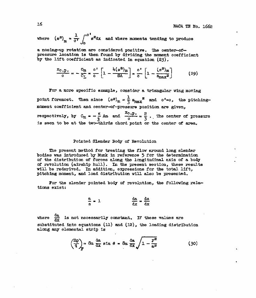
0 a nosing-up rotation are considered positive, The senter-of- pressure location is then found by dividing the moment coeffioient by the lift ooefficient as indloated in equation (23).
For a more speoifio example, oonsidm a [email protected] wing moving
point foremost. Then since (~32)~ = $ k2 and o'=c, the pitching- mamsnt ooefficlent snd oentexwS--pressure position are given,
x0.P. 2 respeotively, by Cm = --EAa and 0 = - . 3 3 I The center of pressure
is seen to be at the two-thirds chord point or the center of szwa,
Pointed Slender Body of Revolution
The presentmethodfor treating the floweroundlong slender bodies was introduced by Munk in referenoe 5 for the determination of the distribution of foroes along the lcagitudinal axis of a body of revolution (airshlp hull). In the present se&ion, these results till be redsrived. In addition, expressions for the total Uft, pitohing mcuuent, snd load distribution will also be presented.
For the slender pointed body of rsvokction, the following rela- tions exist:
a -= 1 da ds -=- S dx dx
where da z is not necessarily constisnt. IT these values are substituted into equations (U) and (l2), the loading distribution alonganyelementalstrip is
KACA TN No. 16Q 17
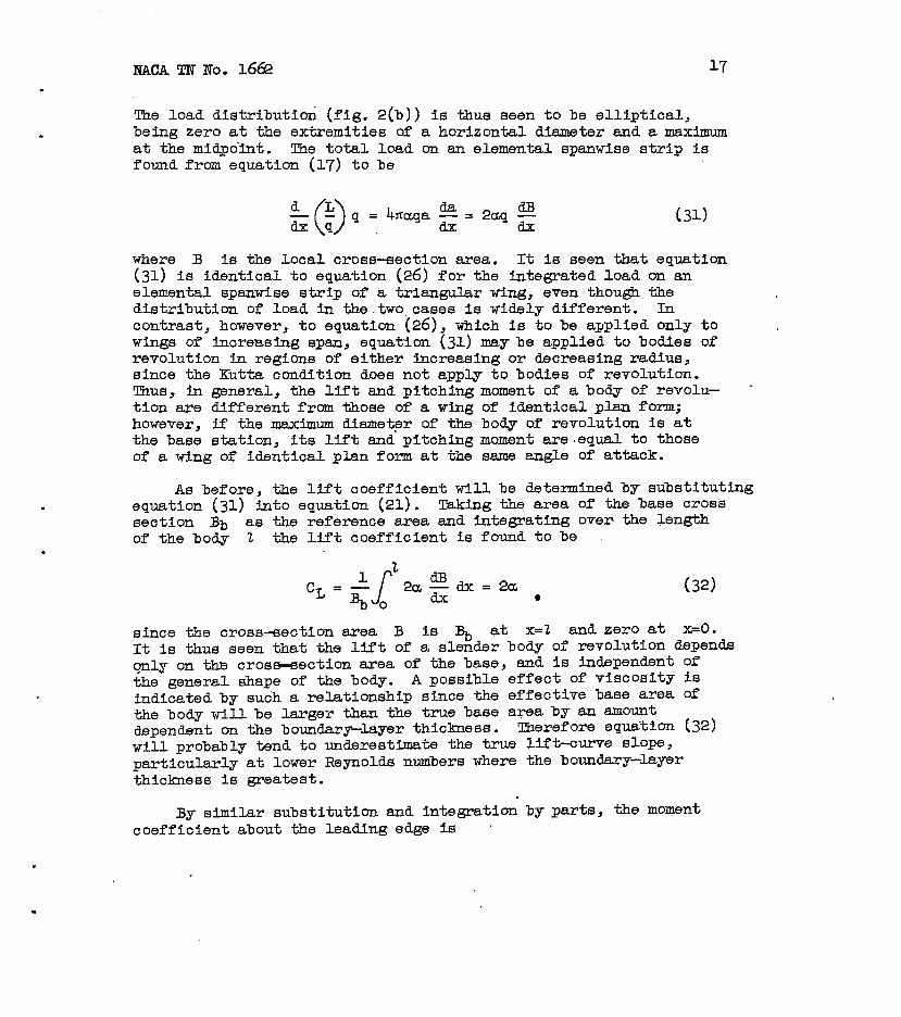
The load distribution (fig. 2(b)) is thus seen to be elliptical, being zero at the extremities of a horizontal diameter and a maximum at the midpoint. The total load on an elemental spanwise stri? is found from equation (17) to be
(31)
where B is the local cross-section area. It is seen that equation (31) is identical to equation (26) for the integrated load on an elemental spanwise strip of a triangular wing, even though the distribution of load in thetwo,cases is widely different. In contrast, however, to equation (26), which is to be applied only to . wings of increasIng span, equation (31) may be applied to bodies of revolution in regions of either increasing or decreasing radius, since the Kutta condition does not apply to bodies of revolution. Thus, in general, the lift and pitching moment of a body of revolu- tion are different from those of a wing of identical plan form; however, if the maximum diemeter of the body of revolution is at the base station, its lift and pitching moment are.equal to those of a ting of identical plan form at the same angle of attack.
As before, the lift coefficient till be determined by substituting equation (31) into equation (21). wing the area of the base cross section Rb as the reference area and integrating over the length of the body 2 the lift coefficient is found to be
(32) l
since the cross-section area B is % at x=2 and zero at x=0. It is thus seen that the lift of a slender body of revolution depends only on the crosmection area of the base, and is independent of the general shape of the body. A possible effect of viscosity is indicated by such a relationship since the effective base area of the body will be larger than the true base area by an amount dependent on the boundary-layer thictiess. Therefore equation (32) will probably tend to underestimate the true lift-curve slope, particularly at lower Reynolds numbers where the boundary-layer thickness is greatest.
By similar substitution and integration by parts, the moment coefficient about the leading edge fs

18 NACA TN No. 1662
-xdx=4a
where Bm is the mean cross-section area (i.e., the volume of the body divided by the length). The center-of-pressure location is then found through use of equation (23) to be
%.p. cm -z--z 125 2 CL %
For a more specific example, consider a cone moping point foremost;- The base cross-section area Is
The mean cross-section area is
The center ofpressure de l&us se.en.to be at the two-thirds point as would be anticipated-by the conical natuzck of the load distribution for this case.
.
Triangular Wing With Conical Body
The first example of a win-ody combination to be considered is that of a conical boQ mounted on a triangular wing so that their vertices coincide. The geometry of such a configuration requires that
da ds where both dx end dx are con&e&s. If these values are
substituted into equations (10) and (l-l) as described in the two preceding examples, the load distribution along any elemental strip on the wing is given by
. .
.
. NACA TN No. 1662
and on the body by
19
(3!m
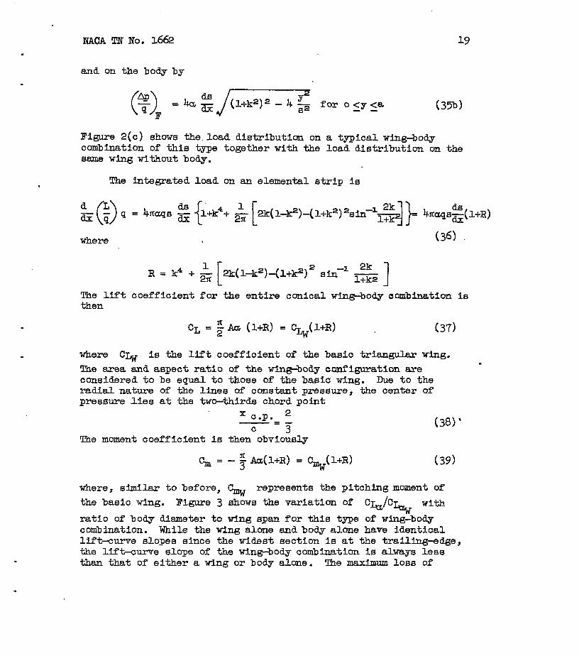
Figure 2(c) shows the.1oe.d distribution on a typical wing4od.y combination of this type together with the load distribution on the same wing without body.
. The integrated load on an elemental strip is
d L z 4 q=
0 4fla-q~ 2 (l+k4+ @k(l-k2)-(l+k2)2sin-1~)= &'cc~qs$+R)
where (36)
R=k4+& 2k(l-k2)-(1+k2)2 aIn-' & 1 The lift coefficient for the entire conical win&body aambination is then
CL = $a (l+R) = CL&l+R) (37)
where Ck is the lift coefficient of the basic triangular wing. a
!lhe area and aspect ratio of the wineody configuration are considered to be equal to those of the basic wing. Due to the radial nature of the lines of constentpressure, the center of pressure lies at the two-thirds chord point
x c.p. 2 -=- C 3
The moment coefficient is then obviously
cm = -5 Acc(l+R) = \(l+R) (39)
(381’
where, similar to before, G represents the pitching moment of the basic wing. Figure 3 shows-the variation of q&/C& with ratio of body d&meter to ting span for this type of wing:body combination. While the ting alone and body alone have identical lift-xrve slopes since the widest section is at the trailwdge, the lift-curve slope of the wing+ody combination is always less than that of either a wing or body alone. The maximum loss of

20 . NACA TIT No. 1662
lift-curve slope (about 8 percent) occurs when the body-radius wlng-semispan ratio is approximately 0.7. c
Triangular Wing on a Semi-Infinite Cylindrical Body
The next example to be considered is that of a triangular wing mounted on a semi-infinite cylTndrical.body. The essential relatlon- ships to be used are that
d.a -= 0 dx
and that ds/dx is constant. By using these relationships as in the previous examples, it is found that no lift is carried on the body ahead of the leading edge of the root chord. Behind this point, however, lift is carried on both the w3zg and body and is distributed on any elemental strip of the wing in a manner described by
=
4+Il-$) -
jt + g’-$ +$44for azyLs i40a) andonthe bodyby
The load distribution at one lmgitudinal station of a typical wing- body configuration of the type considered In this example is shown in figure 2(d). For purposes of comparison, the load distribution over the same wing tithout the body is also indicated in figure 2(d).
The integrated load on an elemental strip is given by
(1-s) (41)
By integration along the length ofthe body, the lift-coefficient for the complete winebody combination, based on the area of the basic

NACA TN No. 1662
triangular wing without fuselage is found to be
21 .
CL -& >'= ~w(d-&~ (42)
It may be seen from equation (42) and fig~e 3 that the addition of a semi-infinite cylindrical body to a triangular wing produces a loss in lift-curve slope just as in the preceding example with the conical body. With the cylindrical body, however, the lift-curve slope has no minimum value, but continues to decrease as the radius- semispan ratio increases until finally, when the latter ratio is one (corresponding to a body without wings), the lift-curve slope is zero. This is as it should be, since a semi-infinite cylindrical body has zero lift-curve slope. The moment coefficient about the vertex of the baeio triangular.wing is
Cm mcA
=-3 1-4%x3+3k4 (
as - -9cbw(l-4~+3.~) .
(43)
The centemf-ressure position of the complete wing-body combination is given by
a 2 %=2+4 %lax
0 i( >’
3 3 -, l+ cx
Since the center of pressure of the wing alone is at the twwthirds chord point, it may readily be seen the second term of equation (44) represents the change due to the addition of the body. Figure 4 shows the variation of the center-of-pressure position with the ratio of body radius to wing semispan. In contrast to the constant center- of--pressure position of the previoue example for the triangula-ing, conicalGbody combination, the center of pressure of the triangular wing, semi-infinite cylindrical body combination moves rearward as the body radius becomes larger with respect to the wing semispan.
Triangular Wing on a Pointed Body
The case of a triangular wing mounted on a pointed bo.dy, closed in an arbitrary manner at the noae but cylindrical along the wing

22 N&CA TN No. 1662
root chord, may be studied by combining the results of two previous examples. The portion of the win@ody combination ahead of the leading edge of the wing root may be considered to be equivalent to the arbitrary body of revolution treated in the second exam@e. The portion:of-the win@ody combination aft of the leading edge of the wdng root is equivalent to a triangular wing mounted on a semi- infinite cylinder as discussed in the preceding example. The load distribution and the integrated load on any elemental apanwise strip are then the s&me as those given in the corresponding example.
The lift coefficient-is found by adding the lift-forces of the component parts of the tin@ody combination and dividing by the dynamic pressure q snd the characteristic area, again taken to be ' the area of the basic triangular wing. The lift coeff-icient is then found to be _
(45)
Figure 3 shows the variation of the Uft-curve slope tith body-radius win6+semispan ratio. A comparison of the 1iftrOurve slopes shows that-the loss in the lift of a triangular ting resulting fram the addition of a body having a pointed nose is much less than that resulting from the addition of a semi-infinite body.
The moment coefficient for this tin@body combination may be found in a manner similar to that used in finding the lift coeff'i- cient, taking care to trensfer the moments of both component parts to the ssme axis. The moment coefficient about the vertex of the . baeic triangular wing is
fic& cp-T1-*s+3~4 ( -)+[2&!2(+~) ] -.
where a represents the radius of the cylindrical portion of the fuselage, 2 the over+~lllength of thewin~odycombination,snd
RAC!A TN No. 1662 23
Bm the mean cross+ectional area (i.e., vol&e divided by length) of the portion of the body ahead of the leading edge of the wing root.
COMPARISON WSI!K O!l?KER RXSUL!lB
As shown in the preceding sections, it 18 a caparatively simple matter to calculate the load distribution, lift, and center of pressure of complete wing+body configurations by means of the present theory. It has been shown that the theory la most applicable at Mach numbers near 'one or for configurations having very low*spect-ratio wings. Its accuracy at other Mach numbers or at larger aspect ratios can best be assessed by comparison with experiment or more nearly exact theory, where available.
CC@~~~iscms with available theoretical and experimental lift- curve slopes of trianguler wings of varying aspect ratio at super-. sonic and subsonic speeds are shown in figures 5(a) and 5(b), respectively. In the supersonic range (fig. 5(a)), the linear theory solution of Stewert, Brown, and others (references 17 and 18) for the variation of lift-curve slope with aspect ratio is shown for Mach numbers of 1.0, 1.2, end 1.4. At a Mach number of 1.0, it la seen that the present theory exactly predicts the linear theory value of the lift-curve slopes of triangular wings of any aspect ratio. Increasing the Mach number decreases the degree of correla- tion at the larger aspect ratios. In summary, this figure indicates that the present theory is very accurate for slender wings at low - supersonic speeds where the wing is neer the center of the Mach cone, and decreases in accuracy as the wing becomes larger with respect to the Mach cone.
In the subsonic case (fig. 5(b)), no lifting-surface theory for the triangular wing comparable to the supersonic triangular- wing theory exists, and all comparisons will be made directly with experiment. Three test points from reference 19 are shown for wings of aspect ratio 0.3, 1.0, end 2.0 tested at very low Mach and Reynolds numbers in the Langley free--flight tunnel. As in the supersonic case, the accuracy is best at very low aspect ratios and decreases as the aspect ratio increases.
A compakison between liftiurve slopes for a complete wing- body combination consisting of a conical body and a triangular wing calculated by the present theoryand by supersonic conical- flow theory is shown in figure 3. A curve presented by Browne, Friedman, andHodes (reference 20) for the lift-curve slope of a

24 * NAGA TN No. 1662
wing+ody configuration consisting of a conical body having a fixed radius of 0.1322 the Mach cone radius and a triangular wing of varying span is shown by the.dotted line in figure 3 tug&her with the corresponding curve obtained by-the present theory, These two curves never differ by as much as 1 percent, indicating that the present theory and the conical-flow theory are in close agreement in predicting the lift-curve slope at supersonic apee,& of a wine body combination consisting of a slender conical body and a low- aspect-ratio triangular wing.
Ames Aeronautical Laboratury, National Advisory Committee for Aeronautics,
Moffett Field, Calif+
Correction tu-Loading on Portion of Fuselage
Aft of WingTrailingEdge
A method for the calculation of the aerodynemic loading on the entire surface of a slender pointed wing-body combination has been presented based on the assumption that the flow in each transverse plane is independent of that in the adJacent planes. It was note.. that the result6 so obtained were not applicable to-the portion of a wing situated behind the widest section because the flow in this region was influenced to a prohibitive degree by the downwash field of the secticms further forward. For the &me reason, the results are also inapplicable to the portion of the fuselage aft of the wing trailing edge, particularly when the fuselage diameter is small in c~parison with the wing span. Since the fuselage is usually extended behind.the trailing edge of the wing, it is desir- able to determine a correction to apply to the loading expresslone.
With assumptions more restrictive then those of the main body ,of this.note, it--is possible to obtain an estimate of the corrected loading on the fusehge afterbody. The necessary aesmptions are thatmthe downwash velocity in the vicinity of the fuselage with fuselage removed is known, and that the downwash velocity remains constant throughout-the entire transverse plane at each longitudinal station. It is immediately apparent-that the latter assumption is not entirely correct, but it 18 true that the downwash velocity is approximately constant over a region of limited lateral extent-at

NACA rCm No. 1662 25
each longitudinal station. Since the forces on a body are produced predominately by the flow field near the body, this assumption should be a valid one as long as the fuselage sections remain in regions of relatively constant downwash velooity in each transverse plarne. This means that the fuselage diameter must be small in comparison with the wing span.
With the foregoing assumptions, the loading on the fuselage afterbody may be determined by an extension of the present method. Consider, as in figure l(a), the flow in the transverse plane as the fuselage afterbody is piercing the x=x0 plane. The flow field corresponding to that of figure l(b) would then be that of the vertical flow around a circ~ular cylinder. As in the previous analysis, the fuselage radius would, in general, appear to be varying with-time. I5 addition, since the downwaah velocity varies with distance behind the wing, the velocity of the vertical flow would also appear to be varying with time. The correct expression for the lift on each strip across the fuselage may then be obtained by substituting the local angle of attack a,-E for the airplane angle of attack a in equation (31) and adding a correction term for the effect of the longitudinal gradient of the downwash velocity. The latter correction term may be determined very simply using the additional apparent mass concept. The correction to the lift force on an elemental strip of unit width across the fuselage afterbody is then given by
Ad L =ii 0
(Al)
In this equation, the additional apparent mass of a unit length of a circular cylinder of cross-section area B is (see, for instance reference 11, p. 77)
and the vertical velocity in any transveraa plane is
w = u(a-4 (A31
where s is the downwash angle. The total lift on each elemental strip of unit width of the fuselage afterbody is then
(A41

26 EACA T!E No. 1662
Since the downwash angle numerically equals the angle of attack on the wing surface immediately ahead of the wing trailing edge and decreases in value as the distance fra the trailing edge increases,
it is apparent that s. has a positive value and that 2 has a negative value. T!bms~, effects of downwash angle in equation (A&) tend to cancel.each other. Another item which should be mentioned is that the downwash behind wings varies considerably with Mach number. Consequently, compressibility will sffeot the lift on fuselage afterbodies.
At subsonic speeds, an upwash exists over the portion of- the body extending ahead of the wing, although this upwash is of considerably smaller ma&tude than the downwash behind the'wing for the slender pointed wings considered here. Equation (Ah) may be applied to determine the magnitude of the corrected loading taking into account the upwash.
By using methods similar to those developed in the main body of this note rather than the shorter additional apparent--mass methods, it can be shown that the load distribution across each strip of the fuselage afterbody is elliptic.
1.
2.
3.
4.
5.
Lennertz, J.: On the Mutual Reaction of Wings and Body. NACA 'TM No. 400, 1927.
Wieselsberger, C., and Lennertz, J.: Airplane Body (Non Lifting System) Brag and Influence on Lifting System. Influence of the Airplane Body on the Wings. Aerodynamic Theory, vol. IV, div. K, ch. III, W. F. Durand, ed., Julius Springer (Berlin), 1935.
Pepper, Perry A.: Minimum Induced-g inWin@?uselage Inter- ference. MACA TN No. 812, 1941.
Mtilthopp, H.: Aerodynamics of the Fuselage. NACA TM No. 1036, 1942.
Munlr, Max. M.: The Aerodynamic Forces on Airship Hulls. NACA Rep. No. 184, 1924.

NACA TN No. 1662 27
6. Jones, Robert T.: Properties of Low4speckRatio Pointed Win@ at Speeds Below and Above the Speed of Sound. 1946.
NACA TN No. 1032,
7. Ribner, Herbert S.: The Stability Derivatives of Low-Aspect- Ratio Trim- Wings at Subsonic and Supersonic Speeti. NACA TN No. 1423, 1947.
8. Tsien, Hsueahen: Supersonic Flow Over en Inclined Body of Revolution. PPm 48-3.
Jour. Aero. Sci., vol. 5, no. 12, Oct. 1938,
9. Laitone, E. V.: The Linearized Subsonic and Supersonic Flow About Inclined Slender Bodies of Revolution. Jour. Aero. SOi., vol. 14, no. 11, Nov. 1947, pp. 631642.
10. Glauert, H.: The Elements of Aerofoil and Airscrew Theory. Cambridge Univ. Press, 2d ed., 1947.
11. Lamb, Horace: Hydrodynmlica. Reprint of sixth ed. (first American ea.), Dover Publications, 1945.
12. Gbthert, B.: Plaue and Three-Diznsnsional Flow at High Subsonic Speeds. NACA !I34 No. 1105, 1946.
13. Bollay, William: A Non-linear Wing Theory eqd its Application to Rectangular Wings of Small Aspect Ratio. Z.A.M.M., vol. 19, Feb. 1939, pp. 21-35.
14. Bollay, William:, A &eory for Rectangular Winge of Small Aspect Ratio. Jour. Aero. Sci., vol. 4, no. 7, May 1937, pp. 2qti96.
15. Prandtl, L.: General Considerations on the Flow of Compressible Fluids. NACA TM NO. 805, 1936.
16. Robineon, A., and Yotig, A. D.: Note on the Application of the Linearized Theory for Ccmpressible Flow to Trensonic Speeds. College of Aeronautics, Cranfield (Bedfordshire) Rep. No. 2, Jan. 1947.
1% Stewart, H. J.: The Lift of a-Delta Wing at,Supereonic Speedi3. Quart. App. Math., vol. 4, no. 3, Oct. 1946, pp. 246~254.
18. Brown, Clinton E.: Theoretical Lift and Drag of Thin Triangulm Wings at Supersonic Speeds. NACA TN No. 1183, 1946.
28 NACA TN No. 1662
19. Tosti, Loui~l E.: Low-Bpeed Static Stability and lkmpinein- Roll Characteristics of Some Swept and Unswept Low-bflpect- Ratio winga. NACA TN No. 1468, 1947.
20. Browne, S. H., Friedman, L., and Hodes, I.: A Wing Body Problem in Supereonic Conical Flow. Preprint of paper presented at the Inst. Aero. Sol. meeting, Jan. 29, 1948.
-s P ‘0
9-r
X phne a /
--
r
fS
Y -d
&f+$
Figure J.- view of wing-body combinatlbn shwhg coortinote axes and two-ohensional flow fields. 2

30 NACA TN No. 1662
4+ z-
nP 9
/ AP 4ads 7
dx
2
/
0
c, a = 0.4 S u! +=a.4
v -----Loudfng ovef wing without &ody
Figure 2. - Lqud distributions over spanwise sections of four configufatiobs.

NACA TR No. 1662 31
.8
.2
1 0 .2 .4 .6 .8
Body radius a Wing semispan ’ T
Tjizx&O
Fig;;uro.; Liff -curve slope ratios for three wing-body configu- 8
. . . -
.

32 .- NACA TN No. 1662
.8
2 L 0 .2 4 .6 .8 LO
Body rudius u .- Wing semkpun 7 v.
figure 4.- Center-of-pressure position of two w/i7g-body configu- rutions.
.

.6
.5
.4
%i .3
.2
.I
Prei
.
f ----Linear theory, ref f7 and f8
.6
.5
.4
CLd: .3
.2
./
0
BiteeM tbewy
Aspect rat/o, a T b. Subsonic
.
figure 5- Coyoarlson of theorehicat and expenhmtal lft-curve s&es fw fnbngular whgs.