nasa tn d-2373 c · a revlew of the stall characmistics of swept wings + by charles w. harper and...
TRANSCRIPT

z c 4 u9 4 z
m h m v n
N A S A TN D-2373 -- NASA TECHNICAL NOTE . -_I - c
=-I
LOAN COPY: RETI == , S f
KJRTLAND AFB, I F s - D z 4
-3
AFWL (WLIL
w = ! d =- m- - 2
L -
A REVIEW OF THE STALL CHARACTERISTICS OF SWEPT WINGS
by Charles W. Harper and Ralph Lo Maki Ames Research Center Mofett Field Calz'J
N A T I O N A L AERONAUTICS A N D SPACE A D M I N I S T R A T I O N 0 WASHINGTON, D. C. JULY 1964
https://ntrs.nasa.gov/search.jsp?R=19640014908 2018-06-07T14:01:15+00:00Z

A REVIEW OF THE STALL CHARACTEFUSTICS OF SWEPT WINGS
By Charles W. Harper and Ralph L. Maki
Ames Research Center Moffett Field, Calif.
NATIONAL AERONAUTICS AND SPACE ADMINISTRATION
For sale by the Off ice of Technical Services, Department of Commerce, Washington, D.C. 20230 -- Price $1.25
A REVlEw OF THE STALL CHARACmISTICS OF SWEPT WINGS +
By Charles W . Harper and Ralph L . Maki
Ames Research Center Moffett Field, C a l i f .
SUMMARY
The unsat isfactory s i tua t ion regarding the understanding of t he s t a l l of swept wings complicates t he design of new a i r c r a f t . presented which serves as a usefu l guide i n determining what must be done empirically t o achieve a given set of wing cha rac t e r i s t i c s . Many general and specif ic s tudies made t o cont ro l t h e s t a l l i n g of swept wings support t he hypothesis; however, it has not been possible t o predict quant i ta t ively the wing cha rac t e r i s t i c s .
A general hypothesis i s
This state of ignorance regarding swept-wing s ta l l could wel l be ser ious. To date the s t a l l cont ro l devices i n use stem from a background of unswept- wing s t a l l i n g experience. There i s no reason t o assume these are necessarily the best solution f o r t he swept wing. A more fundamental understanding of the problem i s needed t o avoid an unnecessary penalty i n low-speed f l i g h t performance and safe ty of swept-wing a i r c r a f t .
INTRODUCTION
The increased appl icat ion of t he swept-wing pr inciple t o high-speed commercial a i r c r a f t has focused a t ten t ion once again on the d i f f i c u l t i e s of achieving, with swept wings, su f f i c i en t ly high maximum l i f t s together with sa t i s fac tory s t a b i l i t y and control f o r landing and take-of f . again" i s used as a reminder t h a t t he problem w a s faced a decade or more ago with the introduction of swept wings in to mi l i ta ry a i r c r a f t design. The solutions t o the h igh - l i f t and associated s t a b i l i t y and control problems which were adopted f o r m i l i t a r y a i r c r a f t cannot necessar i ly be considered adequate f o r commercial a i r c r a f t . That i s , mechanical complication, e lec- t ron ic ass is tance ( i n the form of augmentation), and increased approach and landing speeds do not appear desirable f o r commercial a i r c r a f t .
The phrase "once
Despite t he obvious d e s i r a b i l i t y of achieving a fundamental understanding of these low-speed problems so they could be analyzed i n a quant i ta t ive sense, it i s a f a c t t h a t most, if not a l l , of t he solut ions f o r t he m i l i t a r y a i r c r a f t were reached i n an empirical manner through wind-tunnel s tudies guided by only qua l i ta t ive understanding of t h e phenomena involved. This s i tua t ion exis ted not because of lack of i n t e re s t i n t he fundamentals of t he problem, but simply because time did not allow the painstaking invest igat ions required.
In view of t h e in t e re s t i n wider appl icat ion of swept wings, it is considered of value t o review t h e state of understanding of t h e i r low-speed

problems. conclusions given a re based oi5 a ce r t a in amount of conjecture. it is believed they may serve as a departure point f o r addi t iona l work. The following mater ia l is presented with t h i s in m i n d . drawn from many experiments and chosen only t o i l l u s t r a t e pa r t i cu la r points ; no attempt is made t o be complete in data presentation; where o r ig ina l data a r e avai lable , the published sources a re c i t e d .
Obviously, since the information is not complete or def in i t i ve , Nevertheless,
The data presented a re
NOTATION
A
Ae
b
a
A
A
rl
aspect r a t i o
e f fec t ive aspect r a t i o
wing span
chord
mean aerodynamic chord
wing drag coef f i c Lent
wing l i f t coef f ic ien t
a i r f o i l sect ion l i f t coef f ic ien t
wing pitching-moment coef f ic ien t
Mach number
pressure coef f ic ien t
Reynolds number
chordwise dis tance from a i r f o i l leading edge
angle of a t t ack
taper r a t i o
sweep angle
l o c a l wing spanwise dis tance, f r ac t ion of wing semispan
2
-- I

Subscript s
maX maximum
U upper surface
DISCUSSION
The major low-speed aerodynamic problems facing the designer who chooses low" maximum l i f t and, more important, t he appear-
Not surpr is ingly,
11 t o use swept wings a re the ance , well below maximum l i f t , of extremely nonlinear pitching-moment curves which usually fu r the r l i m i t the "usable" maximum l i f t . po ten t i a l f l o w analysis explains none of t h i s although it does, in i t s various forms, describe with good accuracy a l l the cha rac t e r i s t i c s of swept wings i n the range of l o w lift coef f ic ien ts . Since the swept-wing problems a t low speeds a re a consequence of viscous e f f ec t s , neglected i n po ten t i a l flow analysis, any improvement i n swept-wing charac te r i s t ics w i l l come from improved understanding and cont ro l of t he viscous e f f e c t s . It can be conjec- tured log ica l ly t h a t the viscous e f f ec t of major importance t o these problems is f l o w separation re la ted t o s ta l l of t he s t r a igh t wing; i n the following the term "stalling'l w i l l be used t o specify appears t o have dominant e f f ec t s on wing aerodynamic parameters.
CL values where flow separation
The f irst f igure, showing r e su l t s t m i c a l of many swept-wing investiga- t i ons , i l l u s t r a t e s t he points under discussion. In the low l i f t - coe f f i c i en t range the wing charac te r i s t ics a re s i m i l a r t o those predicted by po ten t i a l flow theory wherein viscous e f f e c t s are ignored. Above about two-thirds maximum l i f t , however, the rate of drag r i s e with l i f t increases rapidly, the l i f t curve slope decreases, and t h e aerodynamic center shifts forward, a l l apparently r e s u l t s of wing s t a l l i ng ; f i n a l l y , t he measured maximum l i f t i s lower than t h a t which would be ant ic ipated on the bas i s of experience with unswept wings alone.
Other experimental r e su l t s , s i m i l a r t o those of f igure 1, led t o extensive research programs directed at finding some design features which would a f f ec t t he s t a l l i n g behavior i n a manner t o raise the CI; a t which s t a l l first occurred, t o raise C b a x , and t o avoid the pitch-up associated with forward s h i f t of t h e aerodynamic center . The solut ions were d i f f e ren t f o r each combination of plan-form sweep, aspect r a t i o , and taper r a t i o . Many attempts were made t o cor re la te these s tudies on the bas i s of geometric param- e t e r s ; some success w a s achieved, notably reference 1, but , i n general, t he correlat ions were of l imited value. It became increasingly c l ea r t h a t some design-chart approach similar t o reference 2 w a s required t o provide the designer with a measure of what swept-wing performance might be e q e c t e d and what geometric f ac to r s could be expected t o influence t h i s performance.
The success of t h e method of reference 2 i n predicting unswept w i n g charac te r i s t ics underscores i t s basic soundness. Although reference 2 could
3
not be successfully applied d i r e c t l y t o swept wings, i6 seemed log ica l t o assume t h i s did not inval idate t h e basic correctness but ra ther t h a t sweep had introduced new or emphasized h i the r to unimportant f ac to r s which must be included.
The remainder of t h i s paper, then, w i l l be a discussion of the e f f o r t s t o re f ine or extend the pr inciples of reference 2 i n an attempt t o a r r ive at an acceptable quant i ta t ive understanding of t he s t a l l i n g of swept wings.
Basic Approach t o the Prediction of Swept -Wing Character is t ics
Prediction of f i rs t appearance of s t a l l . - A s shown i n f igure 1, the charac te r i s t ics of swept wings f a l l i n to t w o regimes: t h a t where the e f f e c t s of v i scos i ty a re s m a l l and where it has been demonstrated t h a t inviscid theories apply, and t h a t where the e f f ec t s of v i scos i ty a re dominant. The f i r s t s tep i n the study of the s t a l l i n g of swept wings, then, would be t o develop a method t h a t defines adequately the upper l i m i t of the inviscid-flow regime and thus would enable adequate design cont ro l of the f ac to r s t h a t determine the f i rs t appearance of s t a l l .
The method given i n NACA TR 572 ( r e f . 3 ) , with various minor refinements, has been shown t o be sa t i s fac tory f o r determining s ta l l on unswept wings. Very important t o the usef&ness of t h i s method i s the degree t o which the e f f ec t s of a i r f o i l sect ion and wing plan form can be studied independently; although such independence cannot be rigorously j u s t i f i e d , t h e benefi ts from making it a su f f i c i en t ly accurate approximation are so tremendous t h a t many studies have been directed a t reducing t h e degree of approximation.
A t l e a s t two changes t o the method of TR 572 are necessary t o include, correctly, fac tors known t o a f f ec t the beginning of swept-wing stall : a span loading theory applicable t o the swept wing must be subst i tuted f o r l i f t i n g - l ine theory, and the concepts of simple-sweep theory must be followed i n applying two-dimensional a i r f o i l da ta . Aside from these changes, the proce- dure is iden t i ca l t o t h a t of TR 572. A s shown i n f igure 2 f o r a typ ica l case, the loading theory w a s used t o es tab l i sh the sect ion l i f t - coe f f i c i en t d i s t r i - bution across the wing (shown by the so l id curve), and simple-sweep theory concepts were applied t o two-dimensional a i r f o i l da ta t o define the d i s t r ibu - t ion of maximum sect ion l i f t coeff ic ient (shown by the dashed l i n e ) . span-loading theory used i n place of t h a t based on the l i f t i n g l i ne w a s the one proposed i n reference 4. instance, t o be accurate f o r a wide range of plan f o r m s , but could be sup- planted with a s t i l l more accurate method. The simple sweep concept w a s used with two-dimensional a i r f o i l data i n order t o i so l a t e three-dimensional f ac to r s . If instead the streamwise section of a swept wing had been examined (not compatible with "simple-sweep" concepts) t he conclusions regarding the three-dimensional f ac to r s would d i f f e r .
The
This has been shown, i n reference 5 , f o r
4

The simple-sweep concept states t h a t t he sect ion charac te r i s t ics on an infinite-span w i n g do not vary as t h e wing i s yawed, provided the section chosen is normal t o t h e constant percent chord l i n e s and provided the r e fe r - ence veloci ty chosen i s p a r a l l e l t o t h i s sect ion. charac te r i s t ics" a re not only the pressure d i s t r ibu t ions associated with inviscid flow but a l so the associated boundary-layer charac te r i s t ics , whether laminar or tu rbulen t . Thus, the changes i n wing charac te r i s t ics as the i n f i n i t e wing i s yawed are e n t i r e l y the r e su l t of change i n reference veloc- i t i e s ; f o r instance, t h e maximum l i f t of t he yawed i n f i n i t e wing w i l l be less than t h a t of t he unyawed wing exactly i n proportion t o the square of t he r a t i o s of e f fec t ive t o free-stream ve loc i t i e s ex is t ing i n the case of t he yawed wing. What theo re t i ca l or experimental proof of the simple sweep concept e x i s t s ?
Included i n the "section
The invariance of the pressure d i s t r ibu t ion has been demonstrated both theo re t i ca l ly ( r e f . 6) and experimentally. t he point fu r the r . Shown on the f igure are comparisons of t heo re t i ca l and measured pressure d is t r ibu t ions f o r a i r f o i l sect ions taken both p a r a l l e l t o t he plane of symmetry and normal t o the quarter-chord l i ne of the 43' ( r e f . 7) and 60° swept wings. through the method of reference 8 as modified i n reference 9 f o r each of t he a i r f o i l sect ions. It can be seen t h a t while the uncambered sections do not show large differences i n pressure d is t r ibu t ion , these differences occur near t h e leading edge where, i n general, the s t a l l i n g charac te r i s t ics are de te r - mined. The differences i n agreement i n t he cases of t he cambered section are la rge . This evidence shows t h a t if two-dimensional da ta are t o be used t o a id i n studying swept-wing s ta l l , they must be applied t o a section normal t o the quarter chord. The invariance of the laminar boundary-layer character- +
i s t i c s has been shown theo re t i ca l ly i n reference 10, and some experimental evidence is included i n the same reference. The invariance of the turbulent- boundary-layer charac te r i s t ics is assumed i n order t o maintain consistency i n the application of t h e simple-sweep concept. It should be noted t h a t t h i s concept implies t h a t t he e f fec t ive Reynolds number f o r a section on a swept wing i s based on the chord and the component of free-stream veloci ty normal t o the 0 . 2 5 ~ l i n e .
Figure 3 i s included t o emphasize
The theo re t i ca l pressure d is t r ibu t ions were obtained
The arguments just presented i n favor of using the a i r f o i l section normal ' to the 0.252 l i n e on a swept wing as t h a t one t o be re la ted t o two- dimensional a i r f o i l charac te r i s t ics lead t o in t e re s t ing conclusions when the low-aspect-ratio wing of high taper i s considered. The l imit ing case of a t r iangular wing (swept leading edge, unswept t r a i l i n g edge) has been examined i n an attempt t o determine how, if a t a l l , section cha rac t e r i s t i c s could be used. The leading-edge pressure d is t r ibu t ions could be re la ted t o two- dimensional r e s u l t s through the sweep of the leading edge. pressure d is t r ibu t ions over the hinge l i ne of a t ra i l ing-edge f l a p appeared t o be re la tab le t o the two-dimensional case through t h e sweep of the f l a p hinge l i n e . It i s d i f f i c u l t t o avoid the conclusion t h a t the simple-sweep concept should be modified t o make the reference a i r f o i l i n the three- dimensional case a curved one described by l i n e s normal t o constant percent chord l i nes (or, perhaps more accurately, normal t o t h e pressure-distribution i sobars ) .
On the other hand,
Study of t he l o c a l s t a l l i n g behavior of t r iangular wings encourages
5

speculation along these l i n e s . would preclude t h e use of two-dimensional t es t r e s u l t s . high-aspect-ratio wings of moderate taper , it should be possible t o avoid t h e curved a i r f o i l concept. effectiveness on plan forms with low sweep of t h e f l a p hinge l i n e .
It is obvious, however, t h a t t h i s hypothesis In any event, f o r
A n important exception may be trail ing-edge f l a p
The accuracy of t h e method under discussion i n predicting the f i rs t occurrence of s ta l l on swept wings has been examined f o r a group of wings of widely d i f f e r ing plan form and p ro f i l e . determined by means of two-dimensional a i r f o i l data modified by simple sweep concepts, and span loadings were calculated f o r increasing l i f t coef f ic ien ts u n t i l t h a t wing l i f t w a s determined wherein t h e span loading curve f i rs t reached the czmax curve. The wing var iables included sweep, aspect r a t i o , taper r a t i o , camber, t w i s t , leading-edge devices of various spans, and trail ing-edge f l a p s . If a sudden increase i n t h e rate of drag rise with l i f t coeff ic ient i s assumed t o be the most ce r t a in precursor of s ta l l , t he r e s u l t s shown i n f igure 4 a re obtained. For these wings, of symmetrical p ro f i l e and varying sweep and aspect r a t i o , a degree of conservatism i s present i n every case - t he predicted value i s on the average about 20 percent lower than t h e experimental value. of accuracy of t he method i n predicting t h e delay i n the f i rs t appearance of s t a l l produced by various wing modifications, and leading- and trail ing-edge h igh- l i f t devices. camber and t w i s t , nose camber, leading-edge slats and f l aps , and t r a i l i n g - edge f l a p s . vative and t o about t he same degree as f o r t he unmodified and/or unflapped wings. While t h e absolute accuracy of t he r e s u l t s obtained by application of the method i s not outstanding, it i s important t h a t t he e r ro r is always i n one direct ion, and t h a t t h e e f f e c t s of design changes a re correct ly predicted. This i s taken as evidence t h a t t he procedure is bas ica l ly correct and accounts f o r the primary e f f e c t s of sweep but t h a t secondary, although important, e f f ec t s have been Ignored. emphasized because, as w i l l be discussed later, t h i s i s important evidence t o be used i n developing a hypothesis f o r t he e f f e c t of wing sweep on the s t a l l i ng of ‘ a i r f o i l sect ions.
That is, czmax d is t r ibu t ions were
Figure 5 has been prepared t o indicate the general order
This f igure shows the predicted and measured e f f ec t s of
The predict ions f o r t he modified and/or flapped wings a re conser-
The conservatism of t h e predictions should be
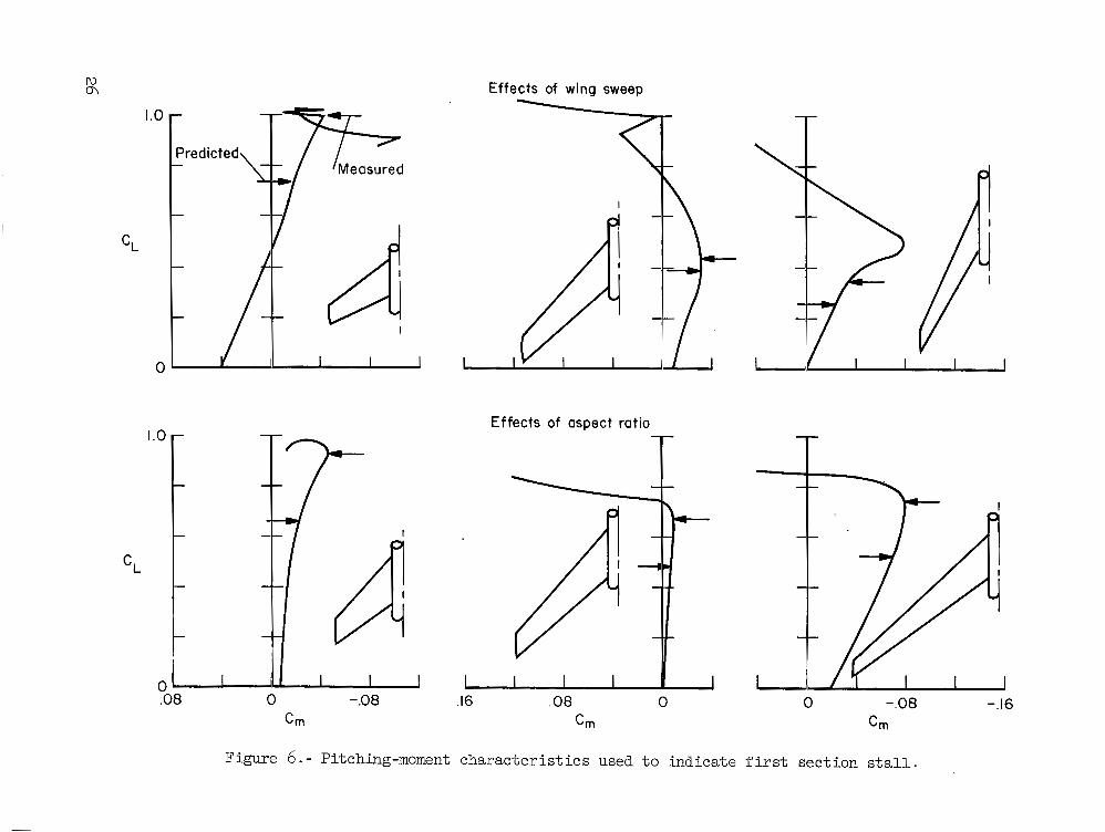
--chanw.- In the foregoing examination of t he accuracy of t h e method, a t ten t ion has been directed only a t the point of sudden drag rise. While t h i s is sui table f o r evaluating the onset of separa- t ion , i n prac t ice it is t h e prediction of more or l e s s sudden pitching-moment changes and t h e i r d i rec t ion which are given prime importance, since s t a b i l i t y i s thereby d i r e c t l y a f fec ted . It has been shown repeatedly t h a t where i r reg- u la r pitching-moment changes occur, they can be t raced t o a marked change i n section l i f t -curve slope at some point on the wing span. Since section l i f t - curve-slope changes generally occur as a r e s u l t of reaching czmx or being very close t o it i n the two-dimensional case, it would be expected t h a t t he outlined procedure might predict t he wing l i f t coeff ic ient where irregular pitching-moment changes would occur. Further, since t h e pitching moment of swept wings i s la rge ly controlled by the span load dYstribution (see ref . 11, p . lo), t h e procedure, i n showing the spanwise locat ion of first stall , would be expected t o predict the d i rec t ion of t h e pitching-moment changes. The
6
. . I1 I I1 . --- -. I I# 1111.1

r e s u l t s presented i n f igure 6 f o r a representative group of wings show the accuracy with which the predictions can be made. r e c t l y t h a t each wing would exhib i t a pitch-up moment after t h e first appear- ance of s ta l l ; it can be inferred, thus, t h a t the method predicted the approximate spanwise location of f i rs t stall . I n some cases the l i f t coeff i - c ien t f o r pitch-up w a s higher than t h a t f o r sudden drag r i s e ; thus, t he f i rs t appearance of s ta l l does not always produce immediate changes i n pitching moment .
The method predicted cor-
The f a c t t h a t t he method appears t o predict t he spanwise location of s ta l l provides a r a t i o n a l bas i s f o r attempting t o design wing modifications t o force the first appearance of s ta l l far inboard and thus produce pi tch- down a f t e r f i rs t s ta l l . A s shown in f igure 7, t he spanwise var ia t ion of
f o r in i t ia l s t a l l can be adjusted so t h a t first s ta l l w i l l decrease t h e wing loading over an area forward of the moment center location and thus produce nose-down moments. Figure 8 shows the e f f ec t of such adjustments on the pitching moments of several wings which i n i t i a l l y had nose-up moments at high l i f t . The pa r t i cu la r device or devices used t o adjust t h e span loading are indicated f o r each wing, and i n each case the arrangement w a s supposed t o produce nose-down moments a t high l i f t . t i o n w a s successful i n only 50 percent of t he cases; t h i s percentage w a s not increased when a la rger number of wings were examined. e a r l i e r t h a t t he method w a s most l i ke ly t o be sa t i s fac tory in cases where nose-up moments, or i n e f f ec t outboard s ta l l , were predicted.
ZmaX
It can be seen t h a t t he predic-
However, it w a s noted
It can be concluded ten ta t ive ly , then, t h a t the method proposed represents a fundamentally sound approach t o the problem of predicting the existence of pitch-up and of prescribing the design changes t o delay and pos- s ib ly t o eliminate the pitch-up. However, it must be concluded a l so t h a t , because of three-dimensional e f f ec t s , t he effectiveness of t h e s ta l l cont ro l device i n two-dimensional experiments may not be a measure of i t s ef fec t ive- ness on a swept wing.
Effect of Mach number.- A l l of t he foregoing comparisons and remarks have been based on cases where shock-induced stalls were not involved. There w a s reason t o believe, however, t h a t t he analysis is applicable t o the high Mach number case. Lack of su i tab ly de ta i led and correlated experimental data ( i .e . , lack of comparable two- and three-dimensional sect ion data at compa- rable Reynolds numbers) makes d i f f i c u l t an exact evaluation of t he process when applied t o high Machnumbers. serve t o encourage fu r the r study i n t h i s d i rec t ion . Shown i n figure 9 is a correlat ion of t he lift coef f ic ien t f o r sudden drag rise f o r several wings a t two Mach numbers. The comparisons of experiment and predict ion a re encour- aging i n sp i t e of the lack of exactly re la ted two-dimensional experimental da t a . Pitching-moment breaks are compared in figure 10. The l i f t coef f i - c i en t s f o r predicted and experimental pitching-moment changes are in fair agreement but t he nose-up moment predicted i n every case w a s not always found experimentally and, when it did occur, it w a s at a higher l i f t coeff i - c i e n t . Thus the method is conservative at moderate Mach numbers as w e l l as at low Mach numbers.
However, comparisons can be made which

If the predict ion of s ta l l on swept wings i s t o be extended t o high Mach numbers, the existence cf an upper l i m i t of Mach number f o r which the method would be applicable must be recognized. Experimental r e s u l t s indicate t h a t as a Mach number of 1 .0 is closely approached, t he shock waves emanating from the wing-fuselage intersect ion and from the wing t i p exer t a control l ing e f fec t on the s t a l l i n g pa t te rn of t he wing; under these conditions any attempt to apply reasoning based on two-dimensional concepts i s obviously i l l o g i c a l .
?"ne Importance of Three-Dimensional Viscous Effects i n the Design of Swept Wings
In order t o i l l u s t r a t e and es tab l i sh some quant i ta t ive measure of the magnitude of t he three-dimensional e f f ec t s on s t a l l i n g , reference i s made t o material i n a report comparing the two-dimensional charac te r i s t ics of an a i r - f o i l section with those f o r the same section on a swept wing ( r e f . 12 ) . The comparisons presented i n t h a t report a re i l l u s t r a t e d i n f igure 11 f o r a 4 5 O sweptback wing having an a i r f o i l section f o r which de ta i led two-dimensional data e x i s t . Adjusting the two-dimensional sect ion l i f t -curve slopes t o cor- respond t o those given by Weissinger theory f o r several span s ta t ions enables a d i r ec t comparison t o be made with data obtained experimentally a t each sta- t ion on the three-dimensional wing. the section cha rac t e r i s t i c s f o r the swept-wing sections a re f o r a section normal t o the quarter-chord l i ne of the wing and a re based on ve loc i ty par- a l l e l t o t h i s sec t ion . A most s t r ik ing point is t h a t a t a l l s ta t ions except the most outboard, t he two-dimensional sect ion maximum l i f t i s de f in i t e ly exceeded and i n increasing measure f o r fu r the r inboard s t a t ions . These data imply, then, t h a t a t no place on the span are the three-dimensional e f f ec t s (probably characterized by the spanwise boundary-layer f l o w ) detrimental t o elma,, and a t most places a re favorable. considered a strong, na tura l fo rm of boundary-layer cont ro l .
In these and a l l following comparisons,
This spanwise flow should, then, be
The phenomenon j u s t described i s not unique t o the wing i n question.
From these data it can Similar r e s u l t s a r e shown i n f igure 12 f o r a group of wings typ ica l of almost a l l wings f o r which such comparisons can be made. a l s o be seen t h a t not only i s maximum l i f t always increased toward the inboard s t a t ions , but t he percent increment i s increased as sweep is increased. For the more highly swept wings, it becomes impossible t o determine a czmax f o r the inboard s t a t ions . The existence of t h i s phenomenqn explains the conser- vatism of the method previously discussed, since t h a t method ignored any such increase i n inboard elmax values .
A s a f i rs t s tep i n the process of accounting quant i ta t ively f o r t he existence of t h i s e f f ec t i n swept-wing design, it i s necessary t o determine jus t how t h i s na tu ra l boundary-layer control i s appl ied. ing can come from examination of t he form of t he separation which l imits cimax f o r t h e two-dimensional and three-dimensional cases . Before doing this , it i s desirable to c l a r i f y what is meant by "form of separation ."
Such an understand-
8

The pa t te rn of separation ex is t ing j u s t p r io r t o t h e maximum l i f t of an a i r f o i l section has three general forms, shown i n f igure 13. F i r s t i s t h a t common t o th ick or highly cambered sections on which separation first appears at the t r a i l i n g edge, then spreads s lowly forward with increasing angle of a t tack t o f i n a l l y f i x exmax; the re la ted pressure d i s t r ibu t ions show a d i s - t i n c t and sharp peak at the leading edge, a lack of complete pressure recov- e ry a t t h e t r a i l i n g edge, and an a rea of constant pressure coeff ic ient over t he af t portion where separation e x i s t s . The second pa t te rn i s that common t o very t h i n sections on which separation of flow at the leading edge appears, followed by reattachment of flow f a r t h e r a f t , and where the point of reat tach- ment moves af t with increasing angle of a t tack t o f i n a l l y f i x czm as it reaches the t r a i l i n g edge; t h e re la ted pressure d i s t r ibu t ion shows a s l igh t peak at t h e leading edge followed by a region of r e l a t i v e l y constant pressure aft t o t h e point of reattachment, and then recovery t o e s sen t i a l ly free-stream pressure. The t h i r d pa t te rn i s t h a t common t o sect ions of about 10-percent thickness and l i t t l e camber on which both types of separation appear and f o r which exmax i s f ixed when t h e forward-spreading trail ing-edge separation becomes suf f ic ien t ly extensive or reaches the aft-moving point of reattach- ment of the leading-edge separation; t he re la ted pressure d i s t r ibu t ion shows both a l o s s of the sharp peak a t the leading edge and lack of recovery a t the t r a i l i n g edge , with some evidence of pressure recovery between these points . On the bas i s of these d i s t inc t ions and f r o m examination of t he chordwise pressure d is t r ibu t ions j u s t p r io r t o s ta l l of a given a i r f o i l section i n two- and three-dimensional flow, an insight can be had in to the mechanism of the na tu ra l boundary-layer cont ro l on swept wings.
Consider again the case of t h i s previously mentioned 450 sweptback wing. Shown i n f igure 14 i s a comparison of t he two-dimensional pressure d is t r ibu- t i o n j u s t p r io r t o with the corresponding ones f o r t h e various span- wise sections of t he wing. Two-dimensional pressure d i s t r ibu t ions show the t y p i c a l evidence of both leading- and trail ing-edge types of separation - both a loss of the sharp leading-edge peak and a lack of recovery at the t r a i l i n g edge. Pressure d is t r ibu t ions f o r several s ta t ions on the span of t he swept wing indicate the same type of separation pa t te rn over the outboard par t of t he span, but a change t o t he t h i n a i r f o i l , leading-edge type of separation on the inboard sect ions. From t h i s , it can be judged t h a t the boundary-layer control i s increasingly e f fec t ive f o r t he t ra i l ing-edge type of separation as the s ta t ions a re nearer the r o o t . Now consider the same wing swept t o 600. A s indicated i n f igure 15(a), t he separation pa t te rn has been changed f r o m t h a t f o r the wing a t 45' sweep; across the e n t i r e span of t h e 60° swept wing the sections show only the leading-edge separation j u s t p r io r t o section m a x i - mum lift. layer control at the t r a i l i n g edge. Now examine the r e s u l t s shown i n f igure l ? (b ) f o r t he 45O swept wing with a highly cambered sect ion, an NACA 64A810. loading, it should not s ign i f icant ly d is turb the balance between leading- and t ra i l ing-edge boundary-layer cont ro l . As indicated by the pressure d is t r ibu- t i o n s i n figure l 5 ( b ) , two-dimensional t e s t s show the sect ion t o have exten- sive t ra i l ing-edge separation j u s t p r io r t o maximum l i f t . Note t h e constant value of pressure coeff ic ient over t he r ea r 25 t o 30 percent of the sect ion. D a t a obtained from various s t a t ions on the wing show the trail ing-edge
czmX
It appears then t h a t increasing sweep in t ens i f i e s t he boundary-
The wing i s a l so twisted, but since t h i s ad jus t s only span
9

separation t o be almost e n t i r e l y suppressed at a l l but t he outermost s ta t ions on the wing. which are a l t e r ed when under t h e influence of t he na tu ra l boundary-layer con- t r o l ex is t ing on a swept wing. Again, these should not be looked upon as unique examples, but ra ther as t y p i c a l of what has been found t o occur i n other cases. t h a t or iginat ing wholly from t h e leading edge, cannot be ascertained because of t he lack of comparable da t a . However, it might be inferred t h a t such leading-edge separation w i l l be delayed a l so , increasingly so with sweep or inboard location, since air-flow studies show a strong spanwise flow of the boundary layer along t h e leading edge as w e l l as aft on t h e wing.
The two cases j u s t discussed cover two types of section s t a l l
The e f f e c t of wing sweep on the t h i r d type of section stall ,
The two major e f f e c t s of wing sweep, suppression of inboard s ta l l , p a r t i - cular ly at the t r a i l i n g edge, through the na tu ra l boundary-layer cont ro l j u s t discussed, together with the outboard movement of t he peak of t he span loading d is t r ibu t ion , which i s increased as taper i s increased, combine t o produce a s t a l l i n g pa t te rn which i s unlike any commonly experienced by unswept wings.
It has been shown ( r e f . 13) t h a t when a t h i n a i r f o i l section i s a t appreciable angle of a t tack , but below maximum l i f t , t h e area of separation lying near the leading edge contains a strong vortex; as the angle of a t tack i s increased, the rearward edge of the area of separation moves toward the t r a i l i n g edge of t he section, and the enclosed vortex increases i n s ize and strength, becoming qui te apparent before the separation spreads t o the t r a i l i n g edge and czmax i s reached. On a swept wing t h e na tu ra l t r a i l i n g - edge boundary-layer cont ro l i n delaying normal s ta l l causes t h i s phenomenon t o appear on sections of much greater thickness than on unswept wings. because. of t he usual sect ion l i f t - coe f f i c i en t d i s t r ibu t ion on a swept wing, the vortex appears, f i r s t , a t the t i p and spreads slowly toward the root as wing angle is increased. In many cases, before t h e leading-edge vortex spreads t o the root, t he t i p sect ions have complete separation, and the vor- t e x has curved back t o leave the wing a t t h e f a r t h e s t inboard point where separation has reached the t r a i l i n g edge. both the or ig in of t he vortex and the point a t which it leaves the wing move inboard. This inboard movement of t he t i p vortex i s pa r t i cu la r ly serious, f o r it produces'much of the drag at high l i f t (s ince it ef fec t ive ly reduces the wing aspect r a t i o ) and many of t he s t a b i l i t y d i f f i c u l t i e s encountered where a high-placed horizontal t a i l is used (s ince it causes rapid increases i n downwash i n the plane of symmetry).
Also,
As angle of a t tack i s increased,
The foregoing analysis , even though la rge ly qua l i ta t ive , o f fe rs an explanation f o r many of t he observed cha rac t e r i s t i c s of swept wings and enables r a t iona l speculation as t o t he best way t o improve swept-wing charac- t e r i s t i c s and as t o probable limits of improvement. No attempt w i l l be made here t o explore i n d e t a i l a l l the implications f o r a l l of the wing character- i s t i c s ; pitching moment w i l l be given primary a t t en t ion .
The e f f ec t of wing sweep on section s t a l l i n g l i m i t s t he d i r e c t applica- t i o n of section data proposed i n the method outlined e a r l i e r . In par t icu lar , it i s c l ea r why the method f a i l e d when it w a s used t o adjust section t o force inboard s t a l l t o occur f irst , and thus give nose-down moments.
czmax
10

Because t h e maximum l i f t of t h e inboard sections i s far above the two- dimensional values, it i s not possible from two-dimensional considerations alone t o know when the t h i s increase must not only exceed that of the inboard sections, but by suf- f i c i e n t margin t h a t outboard s ta l l w i l l not be precipi ta ted by flow of air f romthe s t a l l e d inboard area. To demonstrate t he powerful e f f ec t of sweep on t h i s problem, three wings of d i f f e ren t sweep, 3 5 O , 4 5 O , and 60°, w i l l be considered. Each wing when unmodified showed f i rs t s ta l l a t the t i p and resu l t ing nose-up moments. It w a s apparent t h a t if a s t a l l ed area could be i n i t i a l l y produced anywhere inboard of t he t i p , nose-up moments would be reduced. considerations) were made i n t h e c values of sections lying within various percent spans of t he outboard portion of each wing. A s shown i n figure 16, inboard s ta l l and nose-down moments w e r e produced i n the case of the 3 5 O swept wing where sect ion czmax board 40, 61, and 75 percent of t h e span. i n f igure 17. Note t h a t t he i n i t i a l point of s t a l l could be moved in to the 60- or 40-percent span point, although only the l a t t e r produced the desired nose-down moments. I n contrast t o t he 3 5 O swept wing, when it w a s attempted t o move t h e i n i t i a l s ta l l on t h e 45' swept wing in to the 20-percent span point, it w a s found impossible, as' i n i t i a l s t a l l again appeared a t the t i p . Results presented i n f igure 18 f o r t he 60° wing show t h a t inboard s t a l l and nose-down moments could not be produced i n t h i s case. It i s c l ea r that as sweep w a s increased, the na tu ra l boundary-layer cont ro l increased the inboard section maximum l i f t t o a point where it roughly equalled t h a t of the s lo t t ed outboard sections, and the e f fec t of t he discont inui ty i n spanwise d is t r ibu- t i o n of c w a s l o s t . Note t h a t f o r t he 600 swept wing t h i s w a s t rue even as far outboard as the 60- ercent span point, i n contrast t o t he 45'
cZmx of outboard sections i s su f f i c i en t ly increased;
By means of leading-edge slats, increases (based on two-dimensional
2maX
values w e r e increased over t h e out- Results f o r t he 4 5 O wing are given
2maX
swept wing. (See also r e f . 13. P Although the foregoing shows what i s probably t h e most important th ree-
dimensional e f fec t of sweep not considered by the simple analysis f irst presented, there i s a second important f ac to r t o be considered. AS demon- s t ra ted e a r l i e r , wing sweep has a l so the e f f ec t of changing the location of a i r fo i l - sec t ion separation from the t r a i l i n g edge t o the leading edge, with the effect becoming stronger toward t h e roo t . This e f f ec t must a l so be con- sidered when the e f f ec t of separation-controll ing devices i s estimated f r o m two-dimensional da t a . For example, consider t he e f f ec t of a leading-edge slat on a wing swept 4 5 O and then 600 ( f i g . 19). a 64AO10 which, as noted earlier, has two-dimensional separation both a t the leading and t r a i l i n g edges just p r io r t o maximum l i f t . A slat, if properly drooped, delays primarily t h e appearance of leading-edge separation on a two- dimensional a i r f o i l . A s f igure 19 shows, t he slat a l so served t h i s purpose near t he t i p of a 4.5' swept wing; thus p r i o r t o d is t r ibu t ion shows a loss of pressure recovery at the t r a i l i n g edge, indicat- ing s ta l l i s i n i t i a t e d by t ra i l ing-edge separation. On the contrary, the same slat on the same wing swept t o 600 could not contain the leading-edge separa- t i on ; j u s t p r io r t o t h e sect ion pressure d i s t r ibu t ion shows a loss of leading-edge pressures, while f u l l pressure recovery is real ized a t the t r a i l i n g edge. It i s inferred t h a t t h e na tu ra l boundary-layer cont ro l w a s
The basic a i r f o i l w a s again
cz,,, t he sect ion pressure
cz,,
11

more powerful i n containing trail ing-edge separation than w a s t he slat i n containing leading-edge separation despi te t h e slat e f f e c t s found i n two- dimensional s tud ies . Another wing, swept 6 3 O and with an a i r f o i l section very s i m i l a r t o a 64AOI-0, w a s equipped with, a rea suction boundary-layer con- t r o l at t h e leading edge. It w a s possible, with t h i s form of boundary-layer control, t o prevent leading-edge separation from preceding trail ing-edge separation, as shown on the pressure d i s t r ibu t ion on the r igh t of f igure 19; note t h a t a very high leading-edge peak is reached before pressure recovery at the t r a i l i n g edge decreases. w a s reached at a sect ion l i f t coef f ic ien t near ly twice t h a t reached on the t i p of t he 60° swept wing where leading-edge separation w a s already evident. In attempting t o cont ro l outboard wing s ta l l , consideration must be given not only t o the sect ion t h a t t he two-dimensional s t a l l pa t te rn may be sh i f ted t o make leading-edge s ta l l the dominant problem.
It i s in t e re s t ing t o note t h a t t h i s condition
czmax t h a t must be achieved, but a l s o t o the f a c t
This examination of the two f ac to r s which appear t o a f f ec t most s ign i f icant ly the problem of properly control l ing wing stall , makes it pos- s ib l e t o consider t he general case and show probable reasons f o r t he success or f a i l u r e of some of t he s ta l l -cont ro l l ing devices which have been t r i e d . Obviously, t he most desirable solution i s t o increase t h e maximum l i f t of outboard sections suf f ic ien t ly , since t h i s a l so increases t o t a l maximum wing l i f t . However, it appears from examination of inboard czmax tha% f o r wings swept more than 45O, t he naturalboundary-layer cont ro l causes inboard cz max values t h a t w i l l be d i f f i c u l t or impossible t o exceed a t the t i p no matter what device is used t o increase czma,; f o r instance, on a t y p i c a l wing of 4-50 sweep, it would be necessary t o exceed two-dimensional maximum section l i f t coef f ic ien ts of 2.8 on the outboard s ta t ions , whereas on a t y p i c a l wing of 60° sweep, an outboard required. coef f ic ien ts of about 3.9 were real ized at t h e t i p without successfully moving s ta l l inboard. Where t h i s approach becomes impossible, t he a l te rna t ive of reducing inboard must be resorted t o even a t the cost of reducing wing C h a x . Two general approaches a re possible: f i r s t , t o spo i l the flow over inboard sections and thus counteract t he e f f ec t of boundary-layer control and, second, t o minimize t o t he degree necessary the boundary-layer control at the inboard s t a t ions . The f i rs t approach does not appear promising, although s tudies are so l imited t h a t a d e f i n i t e conclusion is not possible . For instance, leading-edge spoi le rs were attached t o the inboard leading edge of the 3 5 O sweptback wing, t he r e s u l t s f o r which a re shown i n figure 2O(a). The spoi le rs were of a s ize t h a t has been shown by two-dimensional t e s t s t o reduce markedly maximum l i f t . of t he nose-down tendency, which would accompany root stall , f o r any of the spoi le r spans t e s t ed , although there i s evidence t h a t t he root disturbance s l igh t ly reduced the m a x i m u m l i f t of t he t i p sec t ions . Tuft s tudies showed the spoi ler act ion t o be confined t o an a rea j u s t af t of the spoi ler and, i n opposition t o two-dimensional experience, showed complete reattachment of flow over the rearward area. the boundary-layer cont ro l i s suf f ic ien t t o overcome conventional spoi le r act ion on inboard sections; hence, wings of greater sweep cannot be given nose-down moments i n t h i s manner ( a l so see r e f . 14) .
czmaX of over 3.2 (two-dimensional) would be It has been found t h a t on a 6 3 O swept wing, two-dimensional l i f t
c 2 max
The measured pi tching moments show no evidence
It would appear, then, t h a t f o r even 35' of sweep
12

A more promising manner of obtaining nose-down moments (although s t i l l at a cost of reducing maxi" wing l i f t ) i s t o minimize t h e boundary-layer con- t r o l on inboard sect ions. A s an example, consider t he 3 5 O swept wing j u s t discussed with a small discont inui ty added t o t h e wing leading edge a t the 20-percent span point (see f i g . 20 (b ) ) . Wt studies showed the e f f ec t of such a device w a s t o c rea te a vortex lying j u s t above t h e surface of t h e wing and ro ta t ing so as t o sweep the boundary layer inboard, thus minimizing the outboard dra in . Under these conditions, t he root a rea s t a l l e d su f f i c i en t ly ea r ly t o provide t h e nose-down moments. Similar e f f e c t s have been noted i n t h e case of partial-span leading-edge devices which were able t o give nose- down moments. The effect iveness of such devices has been found t o be measur- ably reduced when the inboard end w a s f a i r e d smoothly t o eliminate any sharp discont inui ty .
Perhaps a more d i r e c t w a y of minimizing the boundary-layer cont ro l on inboard sections is through the use of physical dams or fences t o stop or reduce the spanwise boundary-layer control . Experience has shown t h a t only under cer ta in conditions can a fence prove successful; appl icat ion of t h e reasoning of t h i s paper shows the f ac to r s which should govern successful act ion of fences. A t most a fence should cause the sect ions j u s t inboard of it t o have two-dimensional maximum l i f t and type of s ta l l , whereas the sec- t i ons j u s t outboard should show a l l the e f f e c t s of t he na tu ra l boundary-layer cont ro l . If advantage i s t o be taken of t h i s t o produce nose-down moments at high l i f t , fur ther s teps must be taken. Thus, f o r t he case of constant sec- t i ons , t h e wing span-load d i s t r ibu t ion must be adjusted by plan form or t w i s t t o give a maximum loading where first s ta l l i s desired; if wing sect ion alone i s var ied, then t h e maximum l i f t of t h e sections outboard of t h a t one where f i rs t s t a l l i s desired must be su f f i c i en t ly higher than inboard sections t o sustain the addi t ional load introduced by sweep, taper r a t i o , and/or aspect r a t i o . then the location of t he fence must be considered. If t h e sect ion s ta l ls two-dimensionally from the t r a i l i n g edge, then the fence must be placed af t t o stop boundary-layer cont ro l a t t h a t po in t . Under any circumstances, it i s not l i ke ly t h a t a fence w i l l have a dominant e f f ec t , but can only be of a id i n obtaining f u l l benefi t from other devices. With t h i s reasoning i n mind, it i s useful t o examine severa l cases where fences have been t r i e d .
When a proper r e l a t ion is a t ta ined between sect ion loading and czmax,
It has been implied t h a t on the t h i n swept wing with symmetrical sections, a fence is l i k e l y t o prove inef fec t ive . Figure 21 shows the reason f o r t h i s . It i s evident t h a t even i f t he fence wholly overcame the boundary- layer control, inboard s ta l l would not r e s u l t . Figure 22 shows a t y p i c a l case i n which such i s the r e s u l t . For wings of l i t t l e sweep - probably 3 5 O or l e s s - where the span loading i s not appreciably d i f f e ren t from the unswept wing and where the boundary-layer control i s not strong, it i s possible a fence could prove e f f ec t ive .
A number of cases can be shown where a fence w a s able t o increase the effect iveness of a par t ia l -span leading-edge device. This effect iveness va r i e s i n degree from simply increasing the nose-down tendency near maximum l i f t t o producing a nose-down moment where nose-up moments exis ted without t he fence. Generally, fences become most necessary as sweep increases, but it is

I1 I1 I I 111111111 I 11111 I I1 I 1 I 111 I ,I I I I I, ,I I . . .. - . - --
a lso evident t h e i r effect iveness vanishes w i t h su f f i c i en t sweep. It i s evident t he act ion of a combination of par t ia l -span leading-edge device and fence is very similar t o t h a t of t he leading-edge device alone, where an aero- dynamic fence i n the form of a vortex has been shown t o e x i s t . r e s u l t s a re shown i n figure 23( a) (reproduced from f i g . 18 of r e f . 14) and f igure 23(b) (reproduced from f i g . 7 of re f . 15). sweep, ex is t ing nose-down moments were increased, and i n the second case of greater sweep, nose-up moments were nearly eliminated.
m i c a 1
I n the f i r s t case of l e s se r
It i s a l so shown, i n the references j u s t quoted, f o r example, t h a t t he optimum combination of fence and leading edge va r i e s with t ra i l ing-edge f l a p def lect ion. That such should be the case i s c l ea r when consideration is given the changes i n span-load d i s t r ibu t ion and spanwise sect ion maximum l i f t d i s t r ibu t ion engendered by f l a p def lect ions .
The foregoing discussion i s directed only at demonstrating the probable action of fences on swept wings. There a re many d e t a i l s regarding fences which, i n a l l l ikelihood, w i l l never be subject t o generalization since they, i n tu rn , are affected by each var iable i n t h e wing's geometry. Thus, t he exact values of fence location, spanwise and chordwise, and fence height and chordwise extent f o r maximum fence effect iveness must undoubtedly be found experimentally f o r each combination of wing plan form, including leading-edge and t ra i l ing-edge devices and a i r f o i l sect ions. It i s believed, however, t h a t consideration of t he pr inc ip les discussed w i l l aid i n d i rec t ing such research.
Reynolds number e f f e c t s .- All of t h e reasoning and conclusions drawn t o t h i s po in t have been based on r e s u l t s obtained at high Reynolds number. It i s of - in te res t , and pa r t i cu la r ly w i t h regard t o the act ion of fences, t o consider the e f f ec t of reduced Reynolds number on swept-wing cha rac t e r i s t i c s .
The argument has been advanced and supporting evidence produced t h a t the e f fec t ive ve loc i ty in t h e case of t he a i r f o i l sect ion on a swept wing i s closely t h a t one normal t o t he wing quarter-chord l i n e . can be advanced, although the supporting evidence i s meager, t h a t t he effec- t i v e Reynolds number should a l so be based on t h e e f fec t ive veloci ty and the chord normal t o the quarter-chord l i n e . If t h i s i s so, then it i s apparent t h a t the e f fec t ive Reynolds number of any a i r f o i l sect ion on the swept wing is less than the Reynolds number based on the MAC by a f ac to r equal t o , on the average, t he cosine squared of the angle of sweep. Thus, f o r a wing of 4 5 O of sweep, t he Reynolds number based on t h e MAC must be over 2X10⁶, t o reach a section Reynolds number of 1X10⁶. In small-scale tests, then, sec- t i o n Reynolds number can become extremely low. Reference 16 shows t h a t t h e charac te r i s t ics of a i r f o i l sections, pa r t i cu la r ly the values of maximum l i f t , undergo marked changes i n the low Reynolds number range. expected, as has been shown, t h a t swept wings would be excessively sensi t ive t o Reynolds number e f f e c t s even over a Reynolds number range where s t r a igh t wings snow only minor e f f e c t s .
Similar arguments
It would be
The e f f e c t s of Reynolds number on swept wings are fu r the r complicated by the spanwise boundary-layer flow. the e f f ec t of very low Reynolds number i s t o promote extensive trail ing-edge
For example, as reference 16 indicates ,
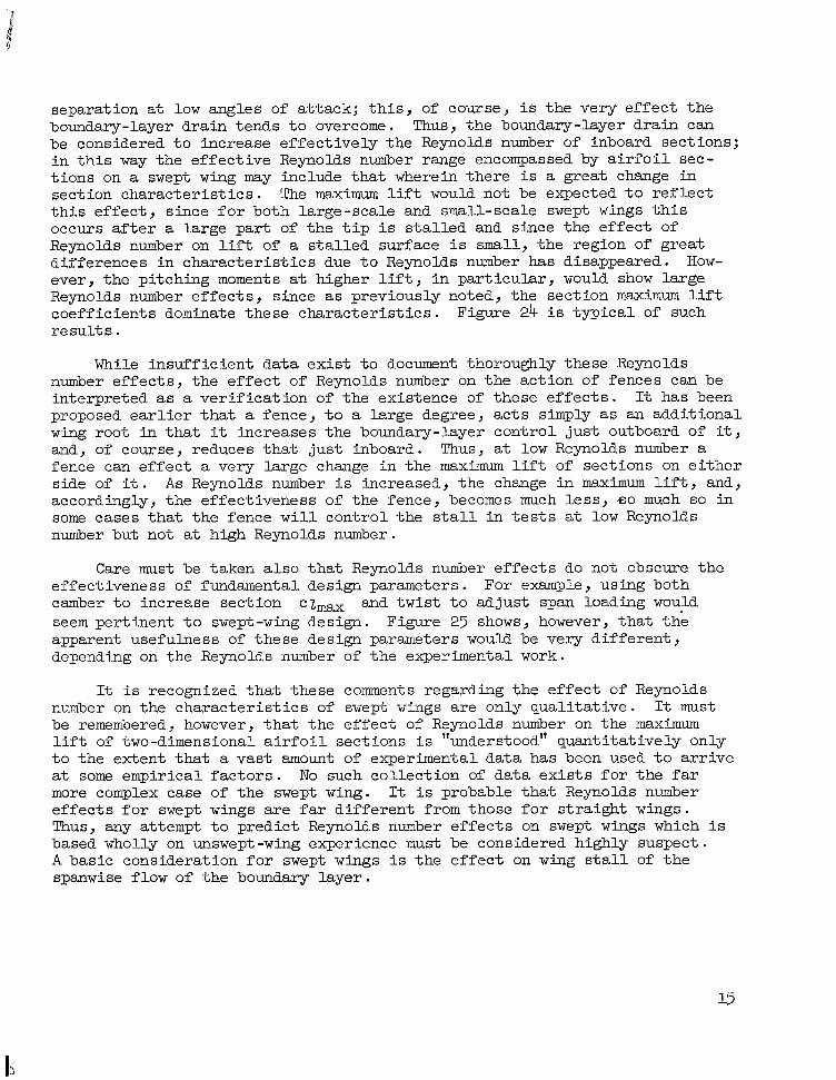
separation a t low angles of a t tack; t h i s , of course, i s the very e f f ec t t h e boundary-layer drain tends t o overcome. Thus, t he boundary-layer drain can be considered t o increase e f fec t ive ly the Reynolds number of inboard sections; i n t h i s way t h e e f f ec t ive Reynolds number range encompassed by a i r f o i l sec- t i ons on a swept wing may include t h a t wherein there i s a great change i n section cha rac t e r i s t i c s . The maximum lift would not be expected t o r e f l e c t t h i s e f f ec t , since f o r both large-scale and small-scale swept wings t h i s occurs after a large pa r t of t he t i p i s s t a l l e d and since t h e e f f ec t of Reynolds number on l i f t of a s t a l l e d surface i s small, t he region of great differences i n cha rac t e r i s t i c s due t o Reynolds number has disappeared. How- ever, t he pitching moments at higher l i f t , i n par t icu lar , would show large Reynolds number e f f ec t s , since as previously noted, the section maximum l i f t coeff ic ients dominate these cha rac t e r i s t i c s . Figure 24 i s t y p i c a l of such r e su l t s .
While insuf f ic ien t da ta ex i s t t o document thoroughly these Reynolds number e f f ec t s , t he e f f e c t of Reynolds number on t h e act ion of fences can be interpreted as a ve r i f i ca t ion of t he existence of these e f f e c t s . proposed e a r l i e r t h a t a fence, t o a large degree, a c t s simply as an addi t iona l wing root i n t h a t it increases t h e boundary-layer cont ro l just outboard of it, and, of course, reduces t h a t j u s t inboard. Thus, a t low Reynolds number a fence can e f f ec t a very large change i n the maximum l i f t of sections on e i t h e r side of it. A s Reynolds number i s increased, t h e change i n maximum l i f t , and, accordingly, the effect iveness of t h e fence, becomes much l e s s , 60 much so i n some cases t h a t t h e fence w i l l control t he s ta l l i n t e s t s at low Reynolds number but not at high Reynolds number.
It has been
Care must be taken a l s o t h a t Reynolds number e f f e c t s do not obscure the effectiveness of fundamental design parameters. camber t o increase section seem pert inent t o swept-wing design. apparent usefulness of these design parameters would be very d i f f e ren t , depending on the Reynolds number of t he experimental work.
For example, using both
Figure 25 shows, however, t h a t t h e czmax and t w i s t t o adjust span loading would
It i s recognized t h a t these comments regarding the e f f ec t of Reynolds number on the cha rac t e r i s t i c s of swept wings a re only qua l i ta t ive . It must be remembered, however, t h a t the e f f ec t of Reynolds number on the maximum l i f t of two-dimensional a i r f o i l sect ions i s "understood" quant i ta t ively only t o the extent t h a t a vast amount of experimental da ta has been used t o a r r ive a t some empirical f a c t o r s . No such col lect ion of da ta e x i s t s f o r t h e far more complex case of t he s w e p t wing. It i s probable t h a t Reynolds number e f f ec t s f o r swept wings are far d i f f e ren t from those f o r s t r a igh t wings. Thus, any attempt t o predict Reynolds number e f f e c t s on swept wings which i s based wholly on unswept-wing experience m u s t be considered highly suspect. A basic consideration f o r swept wings i s t h e e f f ec t on wing s t a l l of t h e spanwise flow of t he boundary layer .

Stat e -of - the - A r t Summary
The foregoing discussion enables a s ta te-of -the-art summary of t h e current understanding of the s t a l l i n g of swept wings. The sa l i en t points can be s ta ted as follows:
Inviscid flow theor ies which a re a modified form of t he analysis of TR 572 conservatively predict t he first appearance of s ta l l on a swept wing.
Up t o t h e first appearance of stall , a reference a i r f o i l on the swept wing chosen normal t o t h e quarter-chord l i n e of the wing generally permits reasonable comparisons between two- and three- dimensional pressure d i s t r ibu t ions .
The conservatism c i t ed i n ( a ) above i s a consequence of a spanwise flow of t he boundary layer which a c t s as a na tu ra l boundary-layer cont ro l system and increases sect ion maximum lift on the swept wing above two-dimensional values .
Once l o c a l s ta l l has appeared, t h e spanwise boundary-layer f l o w serves t o change the s t a l l i n g cha rac t e r i s t i c s of t he unstalled sect ions so they have l i t t l e resemblance t o two-dimensional r e su l t s , e i t h e r i n the value of the l i f t coef f ic ien t at which s t a l l occurs or i n t he type of s ta l l demonstrated.
S t a l l cont ro l devices on a swept wing are important i n a f fec t ing l o c a l sect ion l i f t and the spanwise boundary-layer flow.
summary i n mind it is possible t o examine t h e problem of developing a procedure t o predict swept -wing s t a l l i n g cha rac t e r i s t i c s with a t l e a s t t h e accuracy demonstrated by TR 572 for unswept wings. It m u s t be recognized t h a t t he success of TR 572 depends t o a very large degree on the f a c t t h a t experi- mental two-dimensional sect ion data were used t o produce sa t i s fac tory answers. This i n tu i t i ve ly log ica l s t ep cannot be employed f o r swept wings because three-dimensional boundary-layer conditions on a swept wing differ so from any boundary-layer conditions on a two-dimensional a i r f o i l t h a t s t a l l i n g behaviors are unrelated. Several de ta i led s tudies of boundary layers on swept wings f a i l e d t o uncover any re la t ion , r igorous or empirical, between two- and three-dimensional boundary layers which would a i d i n understanding or predicting three -dimensional separation. The d i f f i c u l t i e s encountered in attempts t o prescribe theo re t i ca l ly the energy t r ans fe r , or shearing stress, i n the two-dimensional turbulent boundary layer indicates t h a t there i s l i t t l e poss ib i l i t y of rea l iz ing success with fundamental s tud ies of three-dimensional boundary layers .
Ames Research Center National Aeronautics and Space Administration
Moffett Field, C a l i f ., Apri l 16, 1964
16

REFERENCES
1. Soule', Hartley A . : Influence of Large Amounts of Wing Sweep on S tab i l i t y and Control Problems of Ai rcraf t . NACA TN 1088, 1946.
2 . Soul;, H . A . , and Anderson, R . F . : Design Charts Relating t o t he S ta l l ing of Tapered Wings. NACA TR 703, 1940.
3 . Anderson, Raymond F . : Determination of the Character is t ics of Tapered Wings. NACA TR 572, 1936.
4 . Maki, Ralph L . : The Use of Two-Dimensional D a t a t o Estimate the Low- Speed Wing L i f t Coefficient a t Which Section Stall F i r s t Appears on a Swept Wing. NACA RM A51E15, 1951.
5 . DeYoung, John, and Harper, Charles W . : Theoretical Symmetric Span Loading a t Subsonic Speeds f o r Wings Having Arbitrary Plan Form. NACA TR 921, 1948.
6 . Jones, Robert T . : Wing Plan Forms f o r High-Speed Flight. NACA TR 863, 1947.
7 . Hunton, Lynn W . , and Dew, Joseph K . : The Effec ts of Twist and Camber on the Aerodynamic Loading and Sta l l ing Character is t ics of a Large-Scale 45' Swept-Back Wing. NACA RM A50J24, 1951.
8. Allen, H . Ju l ian : General Theory of A i r f o i l Sections Having Arbitrary NACA TR 833, 1945. Shape or Pressure Distr ibut ion.
9 . Graham, David: A Modification t o Thin-Airfoil-Section Theory, Applicable t o Arbitrary A i r f o i l Sections, t o Account f o r t he Effec ts of ThicJmess on the L i f t Dis t r ibut ion. NACA TN 2298, 1951.
10. Jones, Robert T . : Effects of Sweepback on Boundary Layer and Separation. NACA TN 1402, 1947.
11. P r a t t , George L . : Effec ts of Twist and Camber on the Low-Speed Longitudinal S t ab i l i t y Character is t ics of a 45' Sweptback Wing of Aspect Ratio 8 at Reynolds Numbers From 1.5X10⁶ t o 4 . 8 X 1 O S as Deter- mined by Pressure Distr ibut ions, Force Tests, and Calculations. NACA RM L52J03aY 1952.
12. Hunton, Lynn W . , and James, H a r r y A.: U s e of Two-Dimensional D a t a i n Estimating Loads on a 4 5 O Sweptback Wing With S l a t s and Partial-Span Flaps. NACA TN 3040, 1953.
13. Salmi, Reino J . : Effects of Leading-Edge Devices and Trailing-Edge Flaps on Longitudinal Character is t ics of Two 47.7' Sweptback Wings of Aspect Ratio 5 .1 and 6 .O a t a Reynolds Nwnber of 6 .ox1o6. NACA RM ~ 5 0 ~ 2 0 , 1950.

14. Graham, Robert R. , and Comer, D . W i l l i a m : Invest igat ion of High-Lift and Stal l -Control Devices on an NACA 64-Series 42O Sweptback Wing With and Without Fuselage. NACA RM L7G09, 1947.
15. Foster, Gerald V . , and Fi tzpa t r ick , James E . : Longitudinal-Stabil i ty Invest igat ion of High-Lift and Stal l -Control Devices on a 52' Sweptback Wing With and Without Fuselage and Horizontal T a i l at a Reynolds Number of 6 .8X106. NACA RM L8108, 1950.
16. Jacobs, Eastman N., and Sherman, Albert: A i r f o i l Section Character is t ics as Affected by Variations of the Reynolds Number. NACA TR 586, 1937.
18

1 I .o
.4 I / Viscous effects
negligible
4 0 4 0 12 16 20
U
Figure 1.- Aerodynamic character is t ics of a typ ica l swept-wing configuration.

Iu 0 I .o
I I I I I I I I I I .2 .4 .6 .8 1.0
Span location, fraction of semispan
Figure 2.- Determination of f irst section stall on a swept wing.

- .. . - . . ._. - ._. - . ._ .__ ...... . . . -. .... . - - . . - .. -. .. - -_ .. . .. . . . . . . . . . . - - . ._ .
- 2.8
-2.4
-2.0
- 1.6
- 1.2
P -.8
-.4
0
.4
.a
-. 2
-. I
0
P
. I
.2
.3
\ I I I I I I
-
cz =o
I I I I I .4 .6 .8 1.0
> .2
x /c
0 Experiment, 7 = 0.815 Theory - chordwise (64AOIO) Theory - streamwise (64A007) -----
I
I I I I - 0 .2 .4 .6 .8 I .o
x /c
I II
(a ) 45' swept wing with NACA &A010 sect ions normal t o the quarter chord l i n e .
Figure 3 . - Comparisons of t h e o r e t i c a l section pressure d i s t r ibu t ions with experimental loadings on f in i t e wing panels.
21

-.4
0
.4 I- I I I I- I -1.6
-1.2
P -.8
-2.4 r
I -
-.
$
.4
I *8 t
I
/ i I
1 1 1 1 1 1 1 I l l
L I I I I I I I I I I 0 .2 .4 .6 .8 I .o
x /c
? 0 Experiment, 7 = 0.50
Theory - chordwise (64AOIO) ---- Theory - streamwise (64A005)
( b ) 60° swept wing with NACA 64A010 sect ions normal to t he quarter-chord l ine.
Figure 3 . - Continued.
22

P
-1.2
-.8 6 CZ = 0.50
0 Experiment, r ] = 0.815 T h eo r y - chord w ise (64A 8 IO) I-
I .8 I-
I - 1 0 .2 .4 .6 .8 1.0
x /c
--- The or y - s t r e a mw i se (6 4 A (5.6 5) 07)
I I I I I I I I I
( c ) 45' swept wing with NACA 64A810 sect ions normal t o the quarter-chord l i n e .
Figure 3 . - Concluded.
23

I .o
CL
0
1.0
CL
-4, b
- / /
0 CD
~
.2
Effects of wing sweep
Effects of aspect ratio
0 .2 I
0
CD
Figure 4.- Drag charac te r i s t ics of several wings used t o indicate f i r s t section s ta l l .

1.6 -
- I
Fl
CL
I\ I I I 1 I 1 1 0 .I6 .32
CD
Increased
0 .I6 .32
CD
I-
C
i Camber and
/ tw is t I
I - I I I I I I
I
-
I I 0 .I6 .32
CD
Figure 3 . - Comparison of predicted and measured values of wing l i f t coefficients for drag r i s e on I
Iu modified wings . Ul
1.0
0
I
Effects of wing sweep
T
Effects of aspect ratio
.I6 .08 0 c m
charac te r i s t ics used t o indicate
0 -.08 -.I6 c m
first section s t a l l .

c
Case I - Plain wing i C hax,
I I I I I I I I I I I I
Case 2 - 60-percent-span high-lift device F' ,-
l e C
2 max --__I--
First i ! - section stal I
-
I I I I I I I I 0 .2 .4 .6 .8 I .o
+ 0 c m
Span location, fraction of semispan
Figure 7 .- The selection of h igh - l i f t devices t o s tab i l ize pitching-moment changes.

0
ern Figure 8.- Wings with h igh- l i f t devices designed f o r longitudinal s t a b i l i t y a t high l i f t .
c,

I .c
CL
C
I .o
C L
0
Predicted
I I I .08
CD
M = .85
0 .08 cD
M =.60
0 .O 8 CD
Figure 9 . - Drag cha rac t e r i s t i c s a t high Mach numbers of severa l wings used t o -indicate f irst sect ion s ta l l .

W 0
I .o
CL
0
- I
Predicted 1
I
CL
.08 0 -.08 cm
Figure 10. - Pitching-moment
.08 0 -.08 cm
I
4 M =.60
charac te r i s t ics at high Mach numbers indicate f irst section s ta l l .
of several wings used t o

I
al
Figure 11. - Comparisons of two- and three -dimensional experimental section l i f t curves; NACA 64A010 sections.

w Iu A35
A45
A60
Wing local lift curves
Two-dimensional section in oblique flow
--------
Angle of attack
Sweep
Aspect ratio
Mach n 0.
Figure 12.- Effect of sweep, aspect ratio, and Mach number on comparison of two- and three- dimensional lift curves.

1 J
Trailing -edge separation spreading forward to fix cI
mox - Thick or cambered section lp
Leading -edge separation g af t to f i x ct
max - - Thin uncambered section
Separation spreading a f t
Separation spreading
Moderate thickness and camber
Figure 13.- I l l u s t r a t i o n of th ree types of section stall.
33

w c
Three - dimensional
---- Two - dimensional
x /c
Figure 14 . - Comparisons of two- and three-dimensional experimental pressure d is t r ibu t ions at - NACA 64AOlO sect ions. 2ma.x’

Inboard - Out board
( a ) Effect of sweep, NACA 6 4 A O I O a i r fo i l
C T h r e e dimensional Two dimensional \
Chord (b) Separation patterns a t c2 . NACA 64A810 air fo i l , 45' sweep
max
Figure 15.- Effect of sweep and a i r f o i l section on separation pat tern a t cz,,,.

Span loading Stal l pattern Force data
Semispan
Figure 16. - Control of pitching moments by spanwise location of f irst s ta l l on a wing swept 3'3'.

Span loading Stall pattern Force data
w 4
I Semispan
4 1
Figure 17.- Control of pitching moments by spanwise 'location of f i rs t s ta l l on a wing swept 4-5'.

W 03 Span loading Force data
Sem isp a n
38 O/o
55 O/O
78 O/o
crn
Figure 18.- Control of pitching moments by spanwise location of f irst s t a l l on a wing swept 60°.

r
' u II /
L x /c
I I I I I x /c
Figure 19.- Full-span stall-control devices on wings of various sweeps.
39

c C J
.- a, Semispan
0
'c -
0
a, 0
.- 'c 'c
(a) Characteristics with sharp edged t
spoiler at leading edge. c 0 .- c i, a, cn
Semis pan
(b) Characteristics with vortex generator at leading edge.
Figure 20 .- Control of s t a l l location by preventing boundary-layer control on inboard s ta t ion ; F-86 a,irplane .

Maximum section l i f t coefficient distribution on wing
t c Q)
0 .- .-
c 0
0 Q) v,
.- t
I Without fence /
Value of two - dimensional maximum l i f t coefficient
Wing span load distribution
Location of fence
0 0.5 I .o Span location, fraction of semispan
Figure 21.- The e f fec t of a fence on the maximum l i f t potent ia l across the span of a swept wing.

Fence at T
Plain wing /
A = 6 A =45O x = .5
1.2
I .o
.8
.6 c~
I + .4
.I 6 .I 2 .O 8 .04 0 -.O 4 c m
Figure 22. - Effect of fences on the pitching-moment characteristics of a swept wing.
42

1.6 -
-
-.4 (a). 42" swept wing
CL
I I I I I .08 -.08
cm -.4 t' (b). 52" swept wing with and without trailing-edge flaps
Figure 23.- Effects on pitching moments of upper surface fences in combination with partial-span leading-edge devices.

-I- .8
R
3.04 x IO6 6.60 8.92
IO. 50
------- -----
-I- -.2
Figure 24. - Effects of Reynolds number on pitching-moment characteristics.

w (D 01 P
I
Wing R
Camber and twist Camber and twist
8 x IO6 3 x IO6
.2 - /e-----
-
.I6 .08 0 -.08 0 8 16 24 c m
a
.08 .I6 -8
cD
0
Figure 25.- Influence of Reynolds number on the effectiveness of twist and camber on a 4>O swept wing.

“The aeronautical and space activitie1 of the United States shall be conducted so as to contribute . . . to the expansion of human knowl- edge of phenomena in the atmosphere and space. The Administration shall provide for the widest practicable and appropriate dissemination of information coiicerning its activities and th< results thereof .”
-NATIONAL AERONAUTICS AND SPACE ACT OF 1958
NASA SCIENTIFIC AND TECHNICAL PUBLICATIONS
TECHNICAL REPORTS: important, complete, and a lasting contribution to existing knowledge.
TECHNICAL NOTES: of importance as a contribution to existing knowledge.
TECHNICAL MEMORANDUMS: Information receiving limited distri- bution because of preliminary data, security classification, or other reasons.
CONTRACTOR REPORTS: Technical information generated in con- nection with a NASA contract or grant and released under NASA auspices.
TECHNICAL TRANSLATIONS: Information published in a foreign language considered to merit NASA distribution in English.
TECHNICAL REPRINTS: Information derived from NASA activities and initially published in the form of journal articles.
SPECIAL PUBLICATIONS Information derived from or of value to NASA activities but not necessarily reporting the results -of individual NASA-programmed scientific efforts. Publications include conference proceedings, monographs, data compilations, handbooks, sourcebooks, and special bibliographies.
Scientific and technical information considered
Information less broad in scope but nevertheless
Details on the availability of these publications may be obtained from:
SCIENTIFIC AND TECHNICAL INFORMATION DIVISION
N AT I 0 N A L A E R 0 N A U T I CS A N D S PAC E A D M I N I ST RAT I 0 N
Washington, D.C. PO546