nasa · the gun was improved by pouring the insulation material in a partial vacuum thereby...
TRANSCRIPT

NASA Technical Memorandum 105875
Anomalous TWTA Output Power Spikes andTheir Effect on a Digital SatelliteCommunications System
Brian D. May and Robert J. KerczewskiNational Aeronautics and Space AdministrationLewis Research CenterCleveland, Ohio
and
James S. SvobodaSverdrup Technology, Inc.Lewis Research Center GroupBrook Park, Ohio
October 1992
NASA
https://ntrs.nasa.gov/search.jsp?R=19930004098 2018-09-05T14:51:09+00:00Z

ANOMALOUS TWTA OUTPUT POWER SPIKES AND THEIR EFFECT
ON A DIGITAL SATELLITE COMMUNICATIONS SYSTEM
Brian D. May and Robert J. KerczewskiNational Aeronautics and Space Administration
Lewis Research CenterCleveland, Ohio 44135
James S. SvobodaSverdrup Technology, Inc.
Lewis Research Center GroupBrook Park, Ohio 44142
SUMMARY00
Several 30 GHz, 60 W traveling wave tube amplifiers (TWTA) were manufactured for the NASALewis Research Center's High Burst Rate Link Evaluation Terminal Project. An unusual operatingproblem characterized by anomalous nonperiodic output power spikes, common to all of the TWTAsproved during testing to significantly affect the performance of a digitally-modulated data transmissiontest system. Modifications made to the TWTAs significantly curtailed the problem and allowed accept-able system performance to be obtained. This paper presents a discussion of the TWTA output powerspike problem, possible causes of the problem, and the solutions implemented by the manufacturer whichimproved the TWTA performance to an acceptable level. The results of the testing done at NASA Lewison the TWTAs both before and after the improvement made by Hughes are presented, and the effects ofthe output power spikes on the performance of the test system are discussed.
I. INTRODUCTION
The High Burst Rate Link Evaluation Terminal (HBR-LET) project was begun in 1987 to addressthe need for an experimental ground terminal to exercise the microwave switch matrix operational modeof NASA's Advanced Communications Technology Satellite (ACTS) described in [1[. For the uplinktransmission, the communication signal is upconverted to a center frequency of 29.634 GHz and amplifiedfor transmission to the satellite.
The link calculation for the uplink transmission indicates that a power amplifier capable of provid-ing 60 W is required. At the HBR-LET uplink operating frequency of 29.634 GHz, current technologyallows that only a traveling wave tube amplifier (TWTA) can meet this requirement. A contract wasawarded to Hughes Aircraft Corporation in February 1989 to provide three TWTAs. Before finaldelivery of the TWTAs, an unusual operating problem became apparent. The RF output of the TWTArandomly deviates from steady state with short spikes of power. The effect of TWTA output powerspikes on the HBR-LET communications link was investigated to assess the acceptability of TWTAperformance. Testing, including bit-error rate (BER) tests, were performed on several TWTAs at theNASA Lewis Research Center. Improvements in materials and processing of the TWTAs resulted invastly improved performance.
Work funded by NAS3-25266, task order 5602.
II. TWTA PROBLEM
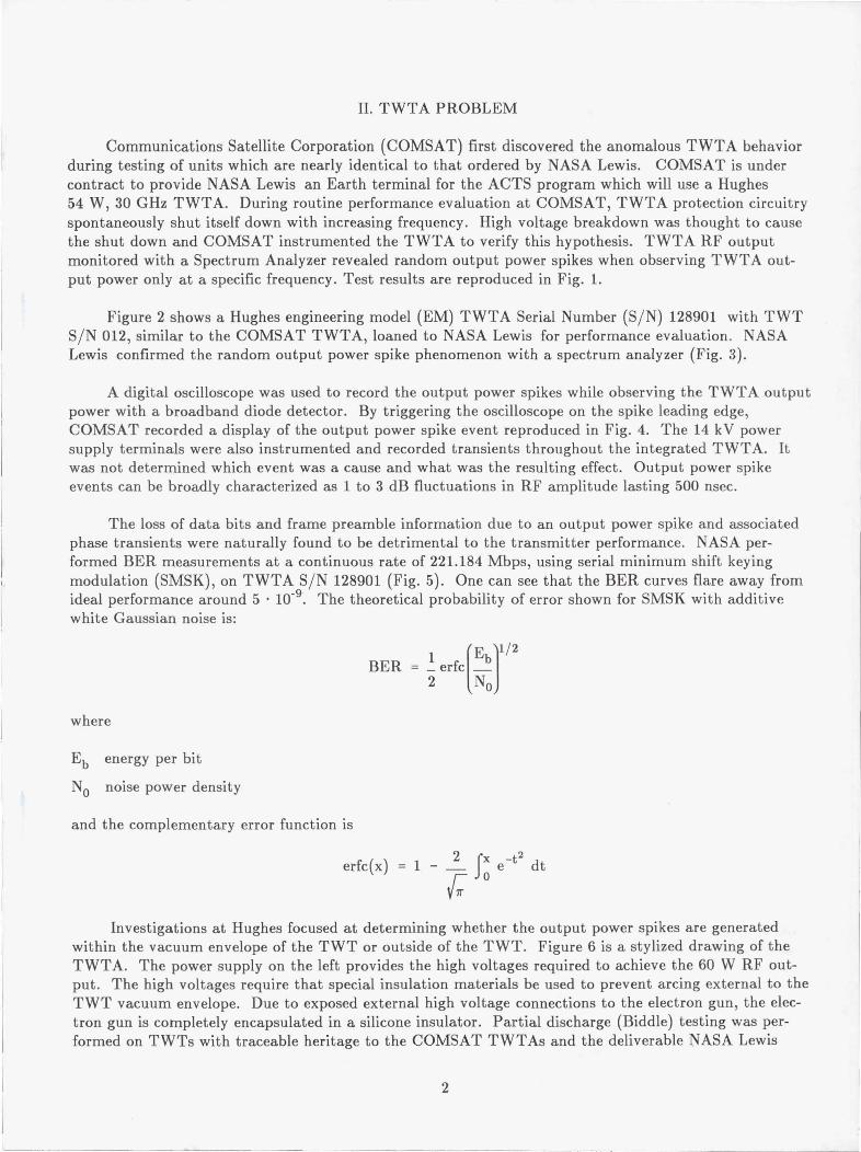
Communications Satellite Corporation (COMSAT) first discovered the anomalous TWTA behaviorduring testing of units which are nearly identical to that ordered by NASA Lewis. COMSAT is undercontract to provide NASA Lewis an Earth terminal for the ACTS program which will use a Hughes54 W, 30 GHz TWTA. During routine performance evaluation at COMSAT, TWTA protection circuitryspontaneously shut itself down with increasing frequency. High voltage breakdown was thought to causethe shut down and COMSAT instrumented the TWTA to verify this hypothesis. TWTA RF outputmonitored with a Spectrum Analyzer revealed random output power spikes when observing TWTA out-put power only at a specific frequency. Test results are reproduced in Fig. 1.
Figure 2 shows a Hughes engineering model (EM) TWTA Serial Number (S/N) 128901 with TWTS/N 012, similar to the COMSAT TWTA, loaned to NASA Lewis for performance evaluation. NASALewis confirmed the random output power spike phenomenon with a spectrum analyzer (Fig. 3).
A digital oscilloscope was used to record the output power spikes while observing the TWTA outputpower with a broadband diode detector. By triggering the oscilloscope on the spike leading edge,COMSAT recorded a display of the output power spike event reproduced in Fig. 4. The 14 kV powersupply terminals were also instrumented and recorded transients throughout the integrated TWTA. Itwas not determined which event was a cause and what was the resulting effect. Output power spikeevents can be broadly characterized as 1 to 3 dB fluctuations in RF amplitude lasting 500 nsec.
The loss of data bits and frame preamble information due to an output power spike and associatedphase transients were naturally found to be detrimental to the transmitter performance. NASA per-formed BER measurements at a continuous rate of 221.184 Mbps, using serial minimum shift keyingmodulation (SMSK), on TWTA S/N 128901 (Fig. 5). One can see that the BER curves flare away fromideal performance around 5 • 10-9 . The theoretical probability of error shown for SMSK with additivewhite Gaussian noise is:
E 11/2
BER = 1 erfc b
2 No
where
Eb energy per bit
No noise power density
and the complementary error function is
erfc(x) = 1 - f x e_tz dt
C oInvestigations at Hughes focused at determining whether the output power spikes are generated
within the vacuum envelope of the TWT or outside of the TWT. Figure 6 is a stylized drawing of theTWTA. The power supply on the left provides the high voltages required to achieve the 60 W RF out-put. The high voltages require that special insulation materials be used to prevent arcing external to theTWT vacuum envelope. Due to exposed external high voltage connections to the electron gun, the elec-tron gun is completely encapsulated in a silicone insulator. Partial discharge (Biddle) testing was per-formed on TWTs with traceable heritage to the COMSAT TWTAs and the deliverable NASA Lewis

TWTAs. A COMSAT residual TWT S/N 009 in its original packaging was subjected to a partialdischarge test, and test results indicate a relatively high number of discharges. A NASA Lewis TWT(S/N 102), not yet insulated, was outfitted with new high voltage wires. Very few discharges werecounted when the gun was submersed in a Freon bath insulation. The liquid Freon substitutes for thegun insulation material. Liquid properties at room temperature and breakdown voltage of 46 kV (acrossa 2.54 mm gap) make Freon an excellent insulator. Results from this test indicate that normal internaldischarges are aggravated by the external insulation material.
It is possible that the RF output power spike may be the result of one of several events originatingwithin the TWT gun. A fraction of the electrons in the electron beam are likely to impact the anode andbe reflected back into the gun. The NASA Lewis team investigating the RF spikes hypothesized thatthese reflected electrons cause positive charge to build-up at the ceramic insulator surface within the gun.An unknown corona or microdischarge mechanism from the focusing electrode are thought to relieve thecharge build-up on the ceramic insulator. The effect of a transient in focusing electrode grid current is tomodulate the electron beam. Common power transformer stack for the cathode, focusing electrode andcollector voltages complicate the problem. Power conditioning circuits are also effected when the tran-sients discharge filter circuits. Similar to capacitors, impurities, air bubbles or delamination of insulationmaterial around the gun produce a voltage gradient which may discharge when power supply transientsoccur.
III. BER TEST PROCEDURE
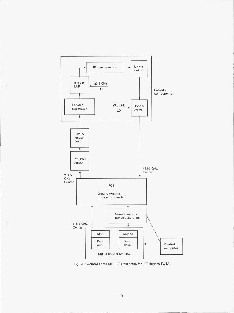
NASA Lewis has developed a Ka-band (30/20 GHz) digital satellite communications systemssimulator known as the SITE (Systems Integration, Test and Evaluation) Project described in [2]. Ablock diagram of the SITE test system is shown in Fig. 7. A data generator in the digital ground ter-minal creates pseudorandom continuous digital data at 221.184 Mbps. The data checker, which is alsocontained in the digital ground terminal, has the job of receiving the returning data bit stream and com-paring it bit-by-bit with the originally transmitted data bit stream. The bit-error rate is calculated bydividing the number of bits in error (Be ) by the total number of data bits transmitted (Bt):
BBER = e
Bt
In this particular test, the Hughes 30 GHz TWTA was inserted into the SITE system after thefrequency conversion system (FCS), which upconverts the SMSK modulator's intermediate frequency(3.375 GHz) to the 30 GHz uplink signal. SMSK is theoretically equivalent to BPSK or QPSK in bit-error rate performance versus E b/No, but is more spectrally efficient [4]. The placement of the TWTAputs it in the same location as it would be a real satellite network.
A solid state noise source with an excess noise ratio of 30 dB is combined with the downlink modu-lated data signal to produce a BER versus E b/No curve. The E b/No can be varied across any userdefined range, usually from about 4 to 18 dB. Two computer controlled attenuators adjust the powerlevels of both the noise and the signal plus noise in 1 dB increments in order to maintain the properEb/No and the proper demodulator input power levels within a 0.5 dB tolerance. E b/No of the testsignal is calculated using the measurements of noise and signal power:
N(dB) _ (P 9 - Pn) + Nbw - R0
3

where
P S measured signal power, dB
Pn measured noise power, dB
Nbw noise equivalent bandwidth of the calibration filter = 393.14 MHz = 85.95 dB Hz
R data rate = 221.184 Mbps = 83.45 dB Hz
The ground terminal receives the returning data bit stream, corrupted with added noise, andcompares it bit-by-bit with the originally transmitted data bit stream to determine BER.
IV. TEST RESULTS FOR UNMODIFIED TWTA
BER measurements on the unmodified TWTA S/N 128901 in Fig. 5 show nearly normal operationat the higher BERs up to 1 • 10 -7 , where the number of errors induced by the output power spikes ismasked by the noise-induced errors. At the higher E b/Nos, however, the number of noise-induced errorsdecreases to the point where the dominant error mechanism is the TWTA output power spikes. Theminimum BER available for HBR-LET operation becomes 1.5 • 10 -8 . This minimum is not adequate formany types of experiments simulating system applications (data transfers, electronic funds transfers,computer networks, etc.) which the HBR-LET may be required to accommodate.
Most disturbing is the complete loss of demodulator carrier synchronization, apparently caused bylarge spikes. This complete loss of data would cause major disruptions of experiments and is thusunacceptable.
V. SOLUTIONS
Hughes proposed modifications to the NASA TWT which were found to minimize the output powerspikes. Gun insulation material was upgraded from a silicone compound with a tear strength of 4.4 kN/mto Dow Corning's Sylgard 577 silicone adhesive with a tear strength of 12.3 kN/m. The Sylgard 577material offers two important advantages: first, the material is less likely to separate from the TWT gunas indicated by the higher tear strength and second, the material does not require a uniform siliconeprimer on the surface to which it will be bonded. Perhaps more importantly, the process of encapsulatingthe gun was improved by pouring the insulation material in a partial vacuum thereby degassing theinsulation material and eliminating bubbles when it sets.
High voltage wire leads to the TWT gun were upgraded from 22 kV rated wire to the AWG 20Reynolds 25 kV rated fluorinated ethylene propylene insulated wire with a silicone casing. The siliconecasing provides better bonding to the Sylgard 577 silicone material.
VI. TEST RESULTS FOR MODIFIED TWTAs
A TWT (S/N 207) of identical design from a new production run was subjected to the oscilloscopetrace test. Freon was once again substituted for the insulation as the gun end of the TWT was sub-mersed. New 25 kV wires provided the high voltages. A typical RF output oscilloscope trace from thistest is reproduced in Fig. 8. Given that Freon is an excellent insulator, it can be concluded that the

phenomenon that results in power spikes, possibly corona, are generated internal to the TWT vacuumenvelope. The magnitude of the spikes recorded during this test is comparable to that recorded on aTWTA with upgrades.
Investigations by Hinckeldey et al. [5] of a similar power spike phenomenon in 1978 resulted in thehypothesis that flashovers internal to the gun discharged power supply filter capacitors. The accumulatedtest data by COMSAT, Hughes and NASA Lewis is consistent with this hypothesis on the internal sourceof power spikes. The observed effect of different insulation materials remains open to interpretation.
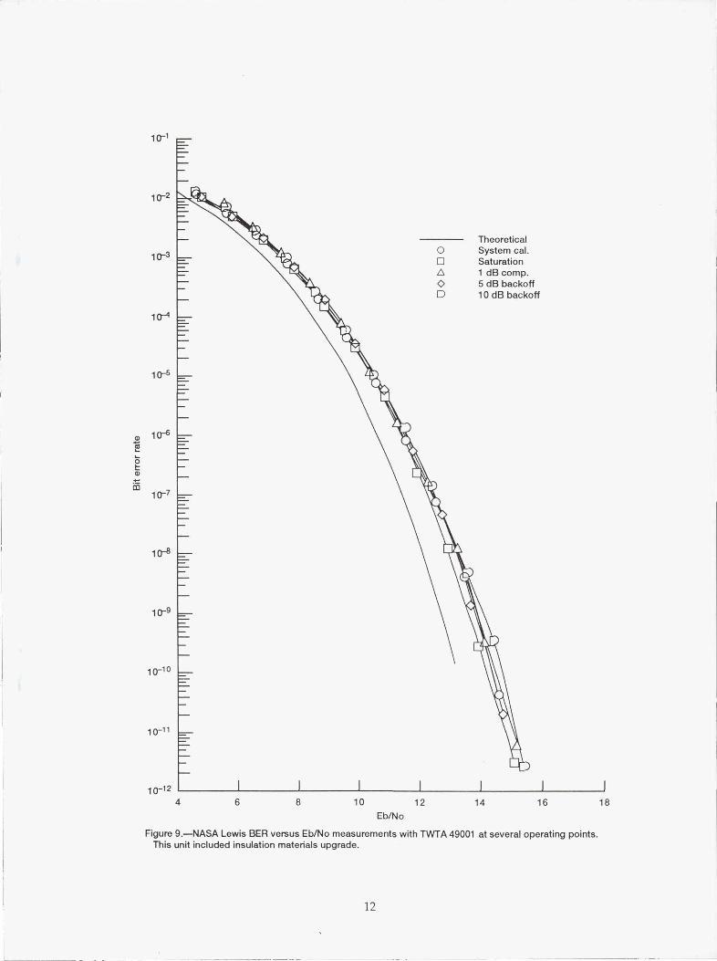
A second TWTA, serial number 49001, with a modified TWT, was fully tested in the same manner asthe unmodified TWTA (S/N 128901. The BER curves are shown in Fig. 9. These curves show a normalBER falloff with increasing E b/No with no minimum BER being reached, down to a BER of 1 • 10-"
The modified TWTAs were found to contribute no additional bit-errors or groups of errors causedby output power spikes and are acceptable for application to the HBR-LET ground terminal.
VII. CONCLUSION
The TWTA power spike anomaly described in this paper may impact only a very few users of theHughes TWTA. Many TWTAs are reported to be operating in the field without incident. The applica-tion for these TWTAs may be insensitive to random power spikes. Transmitter requirements of megabitper second data rates and 1 • 10 -7 BER are at this time unique to the ACTS program. As the informa-tion age matures, services will evolve that match or exceed the ACTS technology. It is these high datarate, low BER satellite services that will be impacted by the power spikes described here.
Paralleling the trend for high data rate services, such as CRAY computer file transfers, and lowBER services, such as electronic funds transfer, microwave equipment suppliers will continually find waysto improve their product. The testing performed on the 30 GHz TWTAs compelled Hughes to seek outbetter materials and processing that enabled their product to meet demanding performance requirements.
ACKNOWLEDGMENTS
The authors wish to thank Mike Hulley of COMSAT and Brian Behler of Hughes for their valuableconsultation and review during the preparation of this paper. COMSAT performed the investigationassociated with Figs. 1 and 4 and provided the test data for reproduction in this paper. Hughes per-formed the investigation associated with Fig. 8, and provided test data for reproduction in this paper.
REFERENCES
[1]F.M. Naderi, and S.J. Campanella, "NASA's Advanced Communications Technology Satellite(ACTS): An Overview of the Satellite, the Network, and the Underlying Technologies," AIAA 12thInternational Communications Satellite Systems Conference, AIAA, New York, 1988, pp. 204-224.(AIAA Paper 88-0797.)
[2]R.V. Latham, High Voltage Vacuum Insulation: The Physical Basis, Academic Press, London, 1981

[3]R.J. Kerczewski and G. Fujikawa, "Performance Measurements for a Laboratory-Simulated 3020GHz Communication Satellite Transponder," AIAA 13th International Communications SatelliteSystems Conference, Part 1, AIAA, New York, 1990, pp. 277-284. (Also, NASA TM-102424.
[4]R.J. Kerczewski, G. Fujikawa, J.S. Svoboda, and P.J. Lizanich, "Effects of Amplitude Distortionsand IF Equalization on Satellite Communication System Bit-Error Rate Performance," AIAA 13thInternational Communications System Satellite System Conference, Part 2, AIAA, New York, 1990,pp. 807-817. (Also, NASA TM- 102415.)
[5]A. Hinckeldey, D. Pfab, and M. Schnaedelback, "Improved TWTs for Reliable High Speed DataTransmissions," Microwave J., vol. 21, pp. 65-67, 1978.
-9.8
Q5a a E
o m-13.8
oO cooaU E
-17.80 20 40 60 80 100
Time, sec —►
Figure 1.--COMSAT test data from spectrum analyzer monitoring a CW signal at29.263 GHz. Spectrum analyzer span is 0.0 Hz, resolution bandwidth is 3 MHz,and video bandwidth is 3 MHz.
6

C-91-54111
Figure 2.—Hughes TWTA engineering model S/N 128901 without cover showingpower supply and RF hardware details.
-445
Q a E0mo vE ^ -48
¢ ^ 3NJ ^ a
E-52
0 20 40 60 80 100
Time, sec —
Figure 3.-NASA Lewis test data from spectrum analyzer monitoring a CW signalat 29.254 GHz. TWTA is operated at 10 dB below saturation. Spectrum analyzerspan is 0.0 Hz, resolution bandwidth is 3.0 MHz, and video bandwidth is 3.0 MHz.
o .4 .8>_ c^ td
0^ o
0occ 0)E
CL 0o0
0 4 c -.8CL = o
o CO E aU
-1.6^ N C
Q ^x -1.2 ~ -2.4
14 18 22 26
Time, µsec
Figure 4.—COMSAT oscilloscope trace of a power spike event for MPA(model 1609H) S/N 001. Top trace is the focusing electrode (grid) current,bottom trace is the RF output power monitored by an inverting crystaldetector.
7

10-1
10-2
10-3
10-4
10-5
10-8
10-9
10-10
1011
10-124 6 8 10 12 14 16 18
10-6
0tm
co 10-7
Eb/No
Figure 5.—NASA Lewis BER versus Eb/No measurements with TWTA 128901 at several operating points.This unit has original insulation materials.

rEp r-- Dow/ silicon adhesive
Power supply mKv /wires nF
in| / /| omv»d / / I
CollectorEf H~--6V Heater Electron gun
EfN~+6V
Cathode^^~1*xv Helix-/
sv"-1*xv
EA+400V
Ceramic
|' '^^
insulatorTraveling wavevacuum envelope |-----------------------
s 13 ~-9m/ | nv|wom,
nrout
Figure B.—Simplified block diagram of the Hughes TWTA.
9
IF power control Martixswitch
30 GHz 23.8 GHzLN R
LO Satellitecomponents
Variable 23.8 GHz _ Upcon-attenuator LO verter
TWTAundertest
Pre-TWTcontrol
19.85 GHzCenter
29.65GHzCenter
FCS
Ground terminalup/down converter
Noise insertion/Eb/No calibration
3.375 GHzCenter
Mod Demod
Data Datagen. check Control
computer
Digital ground terminal
Figure 7.—NASA Lewis SITE BER test setup for LET Hughes TWTA.
10

1000 2000 3000 4000 5000
a) -225crd
S > -275E Eo .
oY -325CO
0o> LL
cc -375
N
2 -420
Time, nanosec —4-
Figure 8—Hughes oscilloscope trace of a power spike event. TWT 8904H, S/N207 with new wires, immersed in FER
10-1
10-'2
1()-3
104
10-5
N 10-6CO
0tm
CO 10-7
10-8
10-9
10-10
10_11
10-124 6 8 10 12 14 16 18
Eb/No
Figure 9.—NASA Lewis BER versus Eb/No measurements with TWTA 49001 at several operating points.This unit included insulation materials upgrade.
12

Form ApprovedREPORT DOCUMENTATION PAGE OMB No. 0704-0188Public reporting burden for this collection of information is estimated to average 1 hour per response, including the lime for reviewing instructions, searching existing data sources,gathering and maintaining the data needed, and completing and reviewing the collection of information. Send comments regarding this burden estimate or any other aspect of thiscollection of information, including suggestions for reducing this burden, to Washington Headquarters Services. Directorate for information Operations and Reports, 1215 JeffersonDavis Highway, Suite 1204, Arlington, VA 222024302. and to the Office of Management and Budget, Paperwork Reduclion Project (0704-0188). Washington, DC 20503,
1. AGENCY USE ONLY (Leave blank) 2. REPORT DATE 3. REPORT TYPE AND DATES COVERED
October 1992 Technical Memorandum4. TITLE AND SUBTITLE 5. FUNDING NUMBERS
Anomalous TWTA Output Power Spikes and Their Effecton a Digital Satellite Communications System
WU-679-40-006. AUTHOR(S)
Brian D. May, Robert J. Kerczewski, and James S. Svoboda
7. PERFORMING ORGANIZATION NAME(S) AND ADDRESS(ES) 8. PERFORMING ORGANIZATIONREPORT NUMBER
National Aeronautics and Space AdministrationLewis Research Center E-6558Cleveland, Ohio 44135-3191
9. SPONSORING/MONITORING AGENCY NAMES(S) AND ADDRESS(ES) 10. SPONSORING/MONITORINGAGENCY REPORT NUMBER
National Aeronautics and Space AdministrationWashington, D.C. 20546-0001 NASA TM-105875
11. SUPPLEMENTARY NOTES
Brian D. May and Robert J. Kerczewski, Lewis Research Center. James S. Svoboda, Sverdrup Technology,Inc., Lewis Research Center Group, 2001 Aerospace Parkway, Brook Park. Ohio 44142. Responsible person,James S. Svoboda, (216) 433-6325.
12a. DISTRIBUTION/AVAILABILITY STATEMENT 121d. DISTRIBUTION CODE
Unclassified - UnlimitedSubject Category 33
13. ABSTRACT (Maximum 200 words)
Several 30 GHz, 60W traveling wave tube amplifiers (TWTA) were manufactured for the NASA Lewis ResearchCenter's High Burst Rate Link Evaluation Terminal Project. An unusual operatin g problem characterized by anoma-lous nonperiodic output power spikes, common to all of the TWTAs proved during testing to significantly affect theperformance of a digitally-modulated data transmission test system. Modifications made to the TWTAs significantlycurtailed the problem and allowed acceptable system performance to be obtained. This paper presents a discussion ofthe TWTA output power spike problem, possible causes of the problem, and the solutions implemented by themanufacturer which improved the TWTA performance to an acceptable level. The results of the testing done atNASA Lewis on the TWTAs both before and after the improvement made by Hughes are presented, and the effects ofthe output power spikes on the performance of the test system are discussed.
14. SUBJECT TERMS 15. NUMBER OF PAGES
Traveling wave tube; Power spike; Bit-error-rate; Advanced communication 1416. PRICE CODEtechnology Satellite
A0317. SECURITY CLASSIFICATION 18- SECURITY CLASSIFICATION 19. SECURITY CLASSIFICATION 20. LIMITATION OF ABSTRACT
OF REPORT OF THIS PAGE OF ABSTRACTUnclassified Unclassified Unclassified
NSN 7540-01-280-5500 Standard Form 298 (Rev. 2-89)Prescribed by ANSI Std. Z39-18298-102