nasa technical note d- · the investigation of prestressed vibrations and buckling of shells ......
TRANSCRIPT

N A S A TECHNICAL NOTE
.m 00
T n z c 4 w 4 z
VIBRATION AND BUCKLING OF PRESTRESSED SHELLS OF REVOLUTION
by P a d A. Cooper
Langley Research Center Langley Station, Hampton, Vu,
N A S A T N -3831.- D--.-._. ~
c', I
I .
li
N A T I O N A L AERONAUTICS A N D SPACE A D M I N I S T R A T I O N W A S H I N G T O N , D. C. M A R C H 1967
f
https://ntrs.nasa.gov/search.jsp?R=19670009308 2018-08-30T05:15:35+00:00Z

TECH LIBRARY KAFB, NM
01130678 NASA T N D-3831
VIBRATION AND BUCKLING O F PRESTRESSED SHELLS O F REVOLUTION
By P a u l A. Cooper
Lang ley R e s e a r c h C e n t e r Lang ley Station, Hampton , Va.
N A T I O N A L AERONAUTICS AND SPACE ADMINISTRATION
For sale by the Clearinghouse far Federal Scientific and Technical Information Springfield, Virginia 22151 - Price $2.00

VIBRATION AND BUCKLING OF PRESTRESSED SHELLS OF REVOLUTION^ By Paul A. Cooper
Langley Research Center
SUMMARY
A linearized set of equations is developed for the infinitesimal vibration and buckling of an axisymmetrically prestressed thin shell with an arbitrary meridional configuration. A finite-difference numerical procedure is given for finding the natural frequencies, buckling loads, and associated mode shapes, and the procedure is applied to calculation of natural frequencies of an unstressed, simply supported cylinder. A closed-form solution is obtained for the simply supported cylinder and is used to verify the numerical procedure, which is then used to solve some other example problems including the vibrations of particular shells of zero and positive Gaussian curvature.
INTRODUCTION
In the design of shell structures for launch vehicles, planetary atmospheric entry probes, or similar structures, knowledge of the natural frequencies and mode shapes of the systems is of fundamental importance in determining their dynamic behavior. For strength considerations of such shells, knowledge of the structural stability of the configurations under varying aerodynamic pressure distributions is important. These shell configurations a r e often too complex to allow solutions in closed form, and numerical techniques a re appropriate for investigating their dynamic and static behavior.
Several numerical methods have recently been developed for static stress analysis and non-prestressed f r e e vibration analysis of general shells of revolution. Static s t ress analysis is considered in references 1 to 4 and non-prestressed vibrations a re considered in references 5 and 6. Membrane and flexural vibrations of toroidal shells a re treated in references 7 and 8 on the basis of the numerical approach of reference 1.
The investigation of prestressed vibrations and buckling of shells requires a consideration of the nonlinear shell equations. The object of this paper is to develop
'The information presented herein is to be included with additional material to be offered in partial fulfillment of the thesis requirements for the degree of Doctor of Philosophy in Engineering Mechanics, Virginia Polytechnic Institute, Blacksburg, Virginia.

differential and difference equations that govern the asymmetric vibration and buckling of a class of shapes of prestressed shells of revolution. These equations a re based on the nonlinear theory of reference 9. A finite-difference procedure similar to that of reference 1 (utilizing and extending the ideas of refs. 7 and 8) is then formulated to obtain solutions of the equations. A comparison with known solutions (refs. 10 to 13) for free vibrations and buckling of a simply supported cylinder indicates the validity of the equations derived in the present paper. In addition, consideration is given to some problems which have not been previously treated in the literature. Natural frequencies are calculated for a cylinder with one end simply supported (with in-plane displacements free) and the other end clamped. Also, a comparison is made between natural frequencies for a cylindrical shell and a similar shell with constant positive Gaussian curvature.
SYMBOLS
a reference length
B extensional stiffness (eq. (16))
D bending stiffness (eq. (16))
Fx,iZe,Ex,EB nondimensional prestress parameters (see eqs. (19) and (52))
E Young's modulus of elasticity
h shell thickness
station number, i = 0, 1, 2, . . . N
kx,ke
K crit ical buckling load parameter
nondimensional curvatures (eqs. (12))
m number of axial half-waves for cylinder (see eqs. (26))
mX moment variable (see eqs. (20))
(e,Me 5 modified moment resultants associated with perturbed statet,Me>M
n number of circumferential waves
2
i

N total number of intervals along the meridian
modified stress resultants associated with perturbed state
modified prestress stress resultants
surface loading
nondimensional radius of c ros s section,
principal radii of curvature (see fig. 1)
total meridional a r c length
p/a
s/atotal nondimensional meridional a r c length,
time
displacement variables defining perturbed state (see eqs. (20))
displacements in meridional (<), circumferential (e), and normal directions, respectively, of undeformed middle surface defining perturbed state (see eqs. (20))
nondime nsional meridional coordinate, [/a
1d ry = - rdx
A length of interval between stations, S/N
‘5 e middle-surface s t ra ins associated with perturbed state
0 circumferential coordinate in undeformed shell
K<’Ke?K<e middle-surface bending s t ra ins associated with the perturbed state
h thickness parameter, ha
I-1 Poisson’s ratio
V mass density
3
X

5 meridional coordinate in undeformed shell
P cross-sectional radius (fig. 1)
V57Ve7 V middle-surface rotations associated with perturbed state
p r estres s meridional rotation
w natural frequency
2a =a 2 w 2 v ( 1 - p2) frequency parameterE
Notations Used to Identify Load and Deformation Variables:
Unmarked variables indicate variables associated with perturbed state only.
r> indicates modified variables associated with the total deformation
C ) indicates modified variables associated with the pres t ress state only
( lo indicates physical s t r e s s resultant quantities
The comma before a subscript denotes differentiation with respect to the following subscripted variable. A dot over a symbol indicates differentiation of the quantities with respect to time.
1X 4 column matrices:
'i dependent variable
4 x 4 matrices:
Ai7Bi7Ci7D07DN7E07EN difference-equation coefficients
ejk7fjk boundary-equation coefficients
Fjk,Gjk7Hj equilibrium -equation coefficients
'i recursion coefficients
a,P boundary -condition -selection matr ices
4

DEVELOPMENT OF GOVERNING EQUATIONS
The shell geometry is illustrated in figure 1. The location of points on the middle surface of the shell is described by the principal coordinates ((,e), where 5 is the meridional distance measured on the middle surface from one boundary, and 0 is the circumferential angle. Since the shell is axisymmetric, it is completely described by the meridional shape parameter p( 5) which is the radial distance from the axis of revolution to the middle surface of the shell.
The principal radii of curvature of the middle surface, R5([) Re( t),are given by:
and
R = P e i
Figure 1.- Shell middle-surface geometry.
The shell is assumed to have a constant thickness h measured along the normal to the middle surface and boundaries at ( = 0 and ( = s, where s is the total meridional a r c length. The material is assumed homogeneous and isotropic with mass density v, Young's modulus of elasticity E, and Poisson's ratio p.
Governing Nonlinear Equations
General nonlinear shell equations in which s t ra ins are assumed to be small and rotations, moderately small, are given in reference 9. For a shell of revolution, these equations become, when inertia t e rms a r e added,
5

where the comma before a subscript denotes partial differentiation with respect to the succeeding subscripted independent variables ( f or 6) and dots over a quantity denote differentiation with respect to time. The equilibrium equations (2a), (2b), and (2c) represent the sum of forces along coordinates of the undeformed surface, and the perturbed displacements of the middle surface U, V, and W are measured in the direction of the coordinates of the undeformed surface with W measured positive along the outward normal.
The boundary conditions considered on the edges 5 = 0 and 5 = s may be chosen from any combination of the following four pairs of quantities in which either quantity (but not both) of each pair is prescribed:
6

- -
The equations have been derived by use of the Kirchhoff-Love assumptions; that is, normals to the undeformed middle surface remain normal to the deformed middle surface, normal strain is zero, and the normal stress is negligible. Rotary inertia t e rms have been neglected in the moment equations. Modified s t r e s s and moment resultants have been used in the development of equations (2) and (3) and a re defined as follows:
NN e = N g O Me" Re
Y
Me = Me0
The modified transverse shear stress resultants Q t5
and Qs may be found by applying
the definitions in equations (4) to the moment equilibrium equations (eqs. (2d) and (2e)).
7

The quantities N5' Neo, Nteo, N e t , QC,and Qeo represent the total
middle-surface stress resultants (fig. 2(a)), and the quantities M C , Meo, Mte",
N o r m a l
e
(a) Stress resultants and displacements.
L' cpt No-
P@- e5
(b) Moment resultants and rotations.
Figure 2.- Middle-surface quantities.
and Me tO represent the
total middle-surface moment resultants introduced by the same combined effect (fig. 2(b)). No attempt is made to relate these stress and moment resultants to the distribution of stress through the thickness of the shell. The equations of reference 9 have been derived without dependence on such a relationship; thus, any formulation consistent with thin-shell theory is acceptable. According to ref erence 9, the addition of te rms like M?/R to the No quantities in the stress-strain relations does not introduce e r r o r s any greater than those already introduced by neglecting transverse shear flexibility in the Kirchhoff -Love hypothesis. Consequently, the
% quantities may be treated as s t r e s s resultants without introducing an inconsistency in the thin-shell analysis.
The sum of the moments about the normal direction is
Hence, from the definition of the modified s t r e s s resultants
Y Y
N e t = (5)
8

I
Therefore, the sixth equilibrium equation, that of equilibrium of moments about the normal, is identically satisfied by symmetric modified stress resultants.
Vibration and Buckling Equations
In the derivation of the vibration and buckling equations, the total rotations and total s t r e s s and moment resultants are separated into the parts associated with the initial axisymmetric prestress and the par ts associated with the infinitesimal perturbed displacements about the prestressed state. The perturbed quantities can be time dependent for infinitesimal vibration investigations or static for buckling investigations. Symbols with ba r s represent those quantities associated with the prestress conditions and symbols without bars represent those associated with the perturbed state. Thus, the total s t ress state may be completely described by these quantities from the relations:
The total rotations a re
9

and the total surface loading is described by
F5 -- F 5
since no additional surface loading is assumed to be associated with the perturbed state.
Substitution of equations (6), (7),and (8) in equation (2a) yields
where 9-derivatives of barred quantities vanish as a result of axisymmetry of the prestressed state. The prestressed shell is in equilibrium; thus, the sum of the te rms enclosed by the first se t of braces in equation (9) vanishes identically. Furthermore, the perturbation of the shell away from the prestressed configuration is governed by linear theory. Therefore, the nonlinear te rms enclosed by the second pair of braces are neglected .
The te rm in equation (9) enclosed by the third pair of braces (i.e., the interaction between the pres t ress deformation and the perturbation stress resultants) is usually neglected in the procedure followed in the classical linearization process for a cylinder. If this term is neglected, the general assumption is made that the pres t ress rotation is uniformly zero throughout the shell. The e r r o r introduced is usually negligible, but for certain boundary conditions o r for sharply varying surface loads, this te rm may be significant and is consequently retained in this analysis. If p 5 and (p
5 7 5 a re neglected, the problem may be reinterpreted as that of a prestressed but undeformed shell of revolution perturbed about the undeformed state. With this te rm retained, the equilibrium equation in the meridional direction (eq. (9)) reduces to
10

By the same procedure, the remaining equilibrium equations (eqs. (2b) to (2e)) are linearized. Solving equations (2d) and (2e) for Q5 and Qe and substituting for them into equations (2a), (2b), and (2c), eliminates these quantities from the system. The parameters defining the geometry of the middle surface can be nondimensionalized by using a reference length a, as follows:
x = - 5 a
a
and nondimensional curvatures can be defined as
ke = -a
Re
Upon completion of these manipulations, the following equilibrium equations result:
5070 - g N
6) + k
xdx &Me + i ( 3 s - ke)Mte,edx *M 5 + rkxM 5 P - kx dx
11

d2r d r 2 d r 1 dx2 - dx--M -Me,x + ;;i;;M5e,e + 2M5e,xe + 7 Me,ee
Similarly, the boundary conditions (eqs. (3)) a r e given as
N 5 = O or U = O
N + f i e ) q = O or V = O
'p5 = O or M ( = O J
The modified stress-resultant-strain relationships, if physical linearity is assumed, a r e
12

where
B = - Eh 1 - p2
D = Eh3 1 2 ( 1 - p2)
The linearized strain-displacement relationships, from reference 9, reduce to
The middle -surface rotations a r e given in te rms of displacements as
The pres t ress t e rms are given nondimensionally as
5 -- BFX(x) fie = Bee(x)

Reduction to Ordinary Differential Equations
With equations (13) and (15) to (19), the equilibrium equations can be reduced to three partial differential equations with the displacements as the unknown dependent variables where the highest order derivative in x is a fourth-order derivative. How -ever, since the solution, in general, can only be achieved by numerical techniques, the procedure of reference 1 is followed, where dependence on 8 is removed by assuming a solution of the separable type and introducing M 5 as an additional unknown. This procedure yields a set of four second-order ordinary differential equations with variable coefficients. The fourth equation is simply the equation for M I in te rms of the displacements. This reduction in order is essential for the numerical treatment that follows.
A solution is assumed of the form
u = u(x)(cos no)eiwt
v = v(x)(sin ne)eiwt
w = w(x)(cos ne)eiwt
M - Eh3-mx(x)(cos n0)ei w t J 5 - a2
Defining the perturbation displacements in this manner assures compatibility in the 8-coordinate. The special case of axisymmetric torsional vibration or torsional buckling is precluded in this investigation by the introduction of this form of 6-variation. This vibration mode uncouples from the extensional and bending modes (see ref. 14)and may be treated directly by interchanging the sines and cosines in equations (20).
For the buckling problem, the time dependence of the perturbed displacements is removed by allowing w (eqs. (20)) to vanish. The perturbed displacements then represent a possible equilibrium state. Any loading that would maintain this equilibrium state as well as the prestressed equilibrium state is a critical loading for buckling.
Performing the operations indicated and utilizing the following geometric relationships
J 14

which are the Codazzi and Gauss equations, respectively, yields the governing equations, as follows:
F 3 1 ~ "+ G 3 1 ~ '+ H 3 1 ~+ F 3 2 ~ "+ G 3 2 ~ '+ H 3 2 ~
+ FQ3w'' + G 3 3 ~ '+ H 3 3 ~+ F34mx11+ G34mx' + H34mx = 0
G41~1+ H41u + H 4 2 ~ + H44mx = 0+ Fq3w1' + G 4 3 ~ '+ H 4 3 ~
The same procedure yields the boundary conditions, as follows:
ellul + fllu + f 12v + e 1 3 ~ '+ f 13w = 0 or u = 0 (234
f 2 1 ~ + e23w' + f 2 3 ~+ e22v' + f 2 2 ~ = 0 or v = 0 (23b)
+ e 3 2 ~ '+ f 32v + e 3 3 ~ 1e 3 1 ~ '+ f 3 1 ~ + f 33w + e34mx1 + f34mx = 0 or w = 0 (23c)
f 41u + e43w ' = O or m x = O (234
Pr imes denote total differentiation with respect to the nondimensional variable x, and the coefficients are subscripted for convenience in subsequent matrix manipulations. The coefficients Fjk, Gjk, Hjk are given in appendix A in t e rms of the parameters y
and X, where
15
I

m m
For the vibration problem, the frequency parameter a2 occurs in H1l' H22' and H33, where
2 2 ! 2 = a w v ( 1 - p 2 )2
E
CLOSED-FORM SOLUTION FOR CYLINDER VIBRATIONS
The vibratory characteristics of a "freely supported" cylinder (simply supported but unrestrained in the axial direction) with pres t ress deformations neglected a re well known. (See refs. 10, 11, and 12.) Thus, these known resul ts can be used as a check of the validity of the governing equations and of the accuracy of the numerical techniques to be suggested subsequently in this report.
When pres t ress deformations a re neglected and the in-plane s t resses a re constant, the equations (22) reduce to ordinary differential equations with constant coefficients which, for freely supported boundary conditions, have a solution of the form
m mU(X)= Am COS -S 1
v(x) = Bm cos -S
mx(x) = Dm sin - J m = 1,2, . . ."s" where S is the length-radius ratio of the cylinder (a = cylinder radius). The classical procedure of neglecting pres t ress deformations to ensure constant coefficients in the field equations implies that the cylinder is initially prestressed as a shell with free edges and then subsequently supported for vibration.
Equations (26) are substituted into equations (22) to yield a set of linear homogeneous algebraic equations. For a nontrivial solution to exist, the determinant of the coef ficient matrix of the resultant set of equations must vanish. This procedure leads to the characteristic equation
where the coefficients Ai are given in appendix B.
16

Equation (27) has been solved for the frequency parameter for an unstressed c i r cular cylindrical shell with 1-1 = 0.3, h = 0.001, and S = 3; and the results for the axial mode m = 1 are given in figure 3. For the purpose of comparing the results of equation (27) with those given in references 10, 11, and 12, the in-plane inertia te rms are dropped from equations (22a), (22b), and (22c), so that equation (27) is reduced from a cubic to a linear equation in Q2. In all studies performed, the frequencies calculated, when in-plane inertias were neglected, agreed closely with those given in references 10, 11, and 12, and all trends observed in these references were similarly verified.
The effect on the natural frequencies due to the neglect of in-plane inertia is illustrated in figure 3. The e r r o r introduced by this approximation decreases as n increases, the largest e r r o r occurring at n = 2. For n larger than 5 the e r r o r is negligible. For n = 0, the fundamental frequency, which corresponds to pure torsional oscillations, is excluded when the assumption of negligible in-plane inertias is made.
I I I I I I I I I 0 4 a 12 16 20 24 28
Circumferential harmonic wave number, n Figure 3.- Natural frequencies of freely supported circular cylindrical shell.
= !!= 0.001. s = 5 = 3. m = 1. ' a '
17

DEVELOPMENT OF NUMERICAL PROCEDURE
Development of Difference Equations
A numerical procedure is needed for those shells of revolution and loading conditions which do not admit a solution in closed form. The meridian of the shell is divided into increments and a three-point central difference method is used to reduce the differential equations to algebraic form. The distance measured along the meridian between adjacent stations is constant and is represented nondimensionally by A where
A = xi - S = N
and where the subscript i on symbols and matrices indicates the evaluation of the subscripted variable or matrix at the ith station, i = 0, 1, 2, .. .,N and where
S total meridional a r c length of the nondimensional shell, s/a
N total number of intervals
The three-point difference formulas, when applied at the ith station for some function z(x), a r e
Reference 2 indicates that this simple approximation leads to sufficiently accurate results.
The governing equations (22) may be written in matrix form at station i as
FiZi" + G.Z. ' + H . Z .1 1
1 1 = 0 (30)
where
F 1 l 0 F13 0
0 F22 3 0
F3 1 F32 F33 F34
0 0 F43 0 i
18

e22
-
Gi =
H1l
H.1 = 1:; H41
and
G12
G22
G32
0
H12
H22
H32
H42
G13 14
G23 0
G33 G34
G43 0 -
-H13 14
'23 '24
H33 H34
H43 H44
i
i
i
Similarly, all the boundary equations (23) may be written in matrix form at the boundaries, i = 0 and i = N, as
where
ell 0 e 13 0
e23 0
(334 eo,N= [31 e32 e33 e34
0 e43 0 -
19

and where
9-47
pO,N =
r
12
22
f32
0
-1 0
0 "y22
0 0
0 0
(1 - 9 1 ) 0
O (1 - 3 2 )
0 0
0 0 -
13
23
f33 34
0 0i1O,N
-0 0
0 0
3 3 0
0 a44_
(34)
0 0
0 0
(1 - 33) 0
0 (1 - a44
The elements a.. take on the value 1 or 0 depending on the prescribed conditions.JJ
The a- and p-matrices (eqs. (34))a r e used to select the prescribed boundary conditions. If, for example, u = 0 is prescribed at i = 0 then ("1d0 = O andif u is
not prescribed at i = N (Le., if the u displacement is unrestrained in the meridional direction of the undeformed shell), then
( W N = 1. If desired, the present theory can
be extended to allow for elastic and directional supports in the boundary conditions by appropriate redefinition of the a- and p-matrices.
When equations (29)a re applied to equations (30)and (32), the governing equations become
20

I
and the boundary equations become
--@ N ~ N @ N ~ N 2A ‘N-1 -I- (@NfN-I- &)‘N -I-7‘N+I= O J
Equations (36) can be solved for Z-l and ZN+l and the results can be substituted into equation (35) to yield, at i = 0,
and, at i = N,
L
where
-1 0 0
0 1 0 I =
0 0 1 0
0 0 0 i1 -
The difference equations (35), (37), and (38) constitute a complete set of field equations governing the behavior of the perturbed state.
Numerical Solution
The problem is now one of solving a set of homogeneous equations (eqs. (35), (37), and (38)). This set constitutes an eigenvalue problem such that the mode shape Zi is the eigenvector and the frequency parameter a2 is the corresponding eigenvalue for the
21

- -
vibration problem. The eigenvalue for the buckling problem is contained in all barred terms. The fourth equation, being simply the definition of m, in te rms of displacements, will not contain an eigenvalue for either problem. For a nontrivial solution to exist, the determinant of the coefficient matrix must vanish.
The coefficient matrix will be a 12-element-wide band matrix. A convenient technique for solution of this problem can be formulated by modifying the method of references 7 and 8. Such a modification is presented herein to handle the free vibrations and buckling of a prestressed shell governed by four second-order difference equations with two-point boundary conditions.
Define the following (4X 4)matrices:
Fi Gi % = - - - 2A~2
2 Fi Bi = Hi
A2
Fici = -+ -Gi ~2 2A
Equations (35), (37), and (38) may now be written as
AiZi-l + Bizi -I-CiZi+l = 0 (i = 1, 2, . . ., N - 1)
DOZO+ EOZl = 0
ENZN-l + DNZN = 0
22

For such a set of homogeneous equations, a recursion formula for Zi may be written as
(i = 1, 2, . . ., N - 2)
and
zi + Pizi+l = 0 ( i = o if z O # o ) (43)
I( i = N - 1 if Z N # O )
where Pi is a (4 X 4) recursion matrix. To find Pi, combine equation (43) and equation (40) to obtain
-1 Zi + (Bi - AiPi-l) CiZi+l = 0 (i = 1, 2, . . ., N - 1) (44)
Comparison of equation (44) with equation (43) shows that
-1 i i-1) Ci (i = 1, 2, . . ., N - 1) (45)P i = (B.1 - A P
Comparison of equation (41) with equation (43), the latter written at i = 0, shows that
p0 = D ~ - ~ E ~ (46)
From equations (45) and (46), Pi may be found at all points with the exception of the point i = N. This process of determining all required values of Pi in t e rms of Po is in essence a Gaussian elimination process.
Equation (43) written at i = N - 1, in combination with equation (42), yields
E ZN # 0, then for a solution to exist,
Therefore, any frequency parameter SZ2 (or buckling parameter in the corresponding stability problem) which satisfies equation (48) contains a natural frequency (or critical load) of the system. The natural frequencies can be found by trial and e r r o r by selecting successive values for a2,calculating the matrices of equations (39), and using equations (45) and (46) to evaluate the determinant in equation (48). This procedure is continued until the desired zeroes of the determinant a r e found.
The method must be slightly modified for the case ZN = 0. Substituting equation (43) written at N - 2 into equation (40) written at N - l yields
23

(BN-1 - AN-1pN-2)zN-1 = (49)
If ZN-l = 0, then Z i = 0 from equation (43), and the solution is trivial. Therefore
IBN-l .,AN-1pN-21 = (50)
Consequently, for the case ZN = 0, equation (50) is used in place of equation (48) in the elimination process.
After the natural frequencies have been found, the mode shapes are determined by first solving equation (47) for ZN in t e rms of an appropriate normalizing factor. For the case where ZN = 0, equation (49) is used to solve for ZN-l. The remaining Z i t s a r e then determined by using the recursion formula, equation (43).
This numerical procedure is particularly well suited for use with a large number of stations since only the band elements need be retained during the computation process. References 1, 2, and 4 give further advantages in using this general method of solution.
In an investigation of buckling, the procedure must be slightly altered. The external axisymmetric loading 5 and can be given by
P(x)= KD(x) J where 5 and characterize the form of the external applied load and K is a constant governing its magnitude. If linearity between the external applied loads and the prebuckling in-plane s t resses and deformations is tacitly assumed, the prebuckling quantities may be written as
and it follows that
24
- - -where Ex, Eo, @[ characterize the in-plane s t ress and deformation due to 55 and F. These quantities can be found, for example, from the stress program of reference 1. Thus, K becomes the buckling load parameter, and any value of K which allows two (or more) equilibrium states to exist simultaneously defines a critical buckling load for the system. The numerical procedure is followed directly, as before, with trial values of K rather than Q2 selected to satisfy equation (48)or equation (50). With K known, equation (51) yields the critical loading for the particular harmonic wave number n investigated.
Although equation (48) (or eq. (50)) contains all the roots of the system of equations (40), (41), and (42), this method of elimination introduces spurious singularities in the determinants of equation (48) or (50). For some shell configurations and boundary conditions, it is found that the roots and singularities very nearly coincide, and the usual predictor-corrector methods fail to indicate a root if the increments given to the f re quency parameter or buckling load parameter a re too large. Moreover, some of these singularities a r e associated with a change in sign in the value of the determinant even though no zero exists at that value of the frequency or buckling parameter. A technique for avoiding this difficulty is presented in reference 15.
EXAMPLES OF APPLICATION O F NUMERICAL PROCEDURE
Cylinder Vibrations and Buckling
An indication of the accuracy of the numerical procedure is obtained by investigating the free vibration and buckling of an unstressed, freely supported, cylindrical shell. The freely supported boundary conditions are introduced by defining
0 0 0 0 @O,N =
0 0 0 0
The particular shell investigated has the parameters p = 0.3, X = 0.001, and S = 3, where the reference length is taken to be the cylinder radius, so that X is the ratio of the thickness to the radius and S is the ratio of the length to the radius. The calculations a re based on 200 intervals.
The lowest frequency for each circumferential harmonic mode number is found for an unstressed shell and compared with the corresponding results calculated using the closed-form solution of equation (27) with m taken as 1. If S is held constant and
25

m is varied for any n, it can be shown that the lowest frequency will result for m = 1. The numerical and exact results agree to three significant figures or better for all values of n from 1to 15.
The same cylinder is investigated with one edge clamped and one edge freely supported. The clamped edge is introduced by defining
A comparison between the two edge conditions for the lowest frequency for each circumferential harmonic mode number is presented in figure 4. A s expected, introducing the
1.c clamped edge increases the natural frequencies of the system, the lowest natural frequency having a relative increase based on the freely supported cylinder of 26 percent. A s n increases, the effect of the edge conditions appears to diminish rapidly.
The buckling load is found for a closed circular cylinder subjected to uniform hydrostatic
3k0J pressure. The results from the numerical procedure a r e com-
II C pared with the closed-form solu
tions based on Donne11 theory given in reference 13. Pre buckling deformations are neglected in the derivation of refer-
Freely supported both ends -.-.- ence 13; consequently, to allow
Clamped on one end---.---.--- for consistent comparisons, the assumption is made that q 5= 0.
0.0; I I I I I I 1 I I I I I I I For a closed cylinder under -1 3 5 7 9 11 13 15 - Neexternal pressure, N 5
= -.2
Thus, unit s t r e s s conditions
26
I

-characterizing this loading are introduced by letting Eo = -1 and E = - -I x 2’from equations (19) and (52)
Hence,
where No may be taken to be Pp, P is the uniform external pressure (P is a negative quantity), and p is the radius of the cylinder measured to the middle surface. Thus, the buckling load parameter is
K = -0p (54)
EX
The corresponding K from reference 13 in te rms of the nondimensional parameters used in this development is given by
The lowest buckling load occurs for this shell at n = 9. The closed-form solution is generally accepted as giving accurate resul ts for n greater than 4; thus, the closed-form value for K = 0.888 x at n = 9 is a valid basis for comparison. By use of the numerical procedures outlined herein, the crit ical buckling load was similarly found to be at n = 9 and gave a relative e r r o r of 0.68 percent. For n = 1 and n = 2 it is known that the lowest buckling load calculated, when the closed-form solution is used, will be in e r r o r on the high side. The numerical procedure gave relative e r r o r s based on the closed-form solution of -18.13 percent for n = 1 and -54.23 percent for n = 2. These e r r o r s indicate that for these cases the use of the numerical procedure coupled with the more consistent shell theory yields more accurate results.
Vibrations of a Shell of Positive Gaussian Curvature
The previous examples are applications of the numerical procedure for both buckling and vibration of systems governed by equations with constant coefficients. The capabilities of the numerical procedure are further demonstrated by investigating the vibration characteristics of a shell of positive Gaussian curvature with a constant positive
27
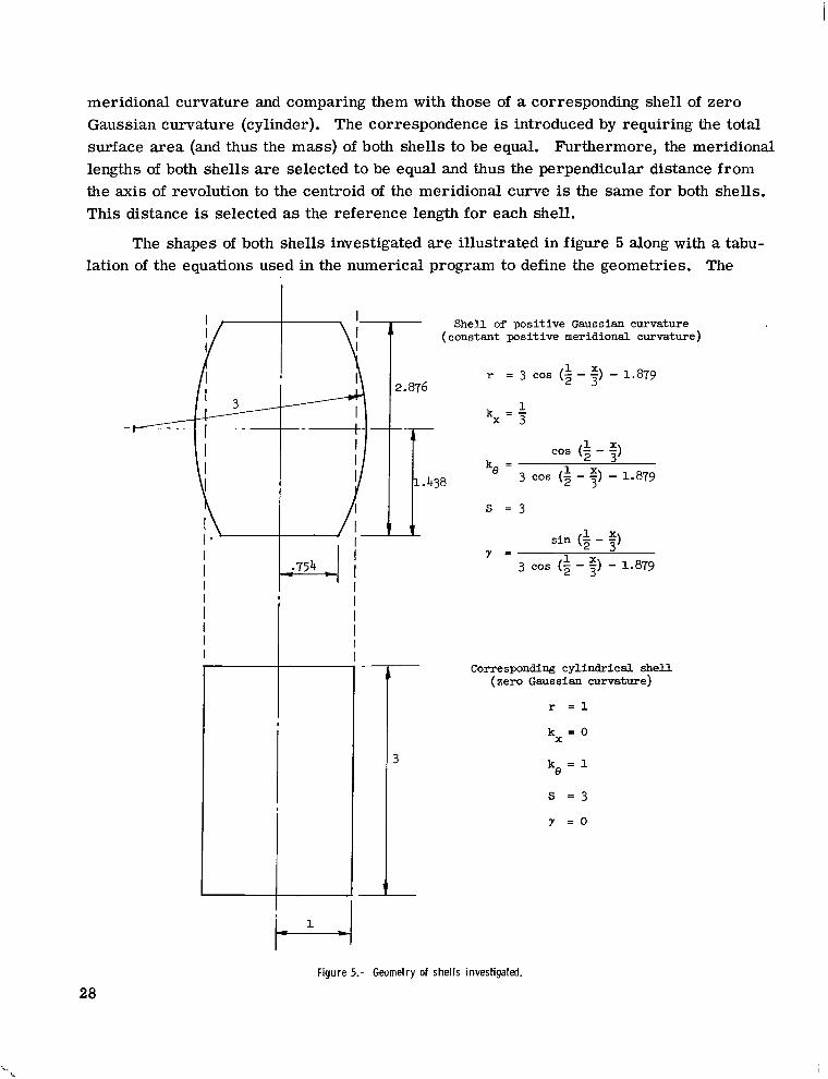
meridional curvature and comparing them with those of a corresponding shell of zero Gaussian curvature (cylinder). The correspondence is introduced by requiring the total surface area (and thus the mass) of both shells to be equal. Furthermore, the meridional lengths of both shells are selected to be equal and thus the perpendicular distance from the axis of revolution to the centroid of the meridional curve is the same for both shells. This distance is selected as the reference length for each shell.
The shapes of both shells investigated are illustrated in figure 5 along with a tabulation of the equations used in the numerical program to define the geometries. The
I I I Shell of positive Gaussian curvature
(constant positive meridional curvature)I
I r = 3 cos (-1- 5) - 1.8792 3
I 3 k = -1 x 3
I -+-
I I I
I 1.438 k = 1e 3 COS (2- ”) - 1.879
I s = 3 I I * . II sin (3 - -)
1
I I cos (21////Y =
3 cos (5 -
1
;)
3
-3 x
1.879
I II I I II I I I
Figure 5.
28
Corresponding cylindrical shell (zero Gaussian curvature)
r = 1
k = O X
k = 1e
s = 3
y = o
Geometry of shells investigated.
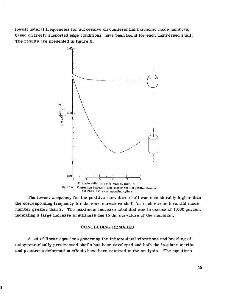
lowest natural frequencies for successive circumferential harmonic mode numbers, based on freely supported edge conditions, have been found for each unstressed shell. The results are presented in figure 6.
6i
CONCLUDING REMARKS
A set of linear equations governing the infinitesimal vibrations and buckling of axisymmetrically prestressed shells has been developed and both the in-plane inertia and pres t ress deformation effects have been retained in the analysis. The equations
29

derived are consistent with first-order thin-shell theory and can be used to describe the behavior of shells with arbitrary meridional configuration having moderately small pre -stress rotation.
A numerical procedure has been given for solving the governing equations for the natural frequencies, buckling loads, and associated mode shapes for a general shell of revolution with homogeneous boundary conditions. The numerical procedure uses matrix methods in finite-difference form coupled with a Gaussian elimination to solve the governing eigenvalue problem.
Examples of applications of the numerical procedure have been presented. Results for natural vibration frequencies and buckling under hydrostatic pressure of a simply supported cylinder were found to be in good agreement with previously published results. A brief comparison between the vibration characterist ics of two geometrically similar shells having positive and zero Gaussian curvature displayed the markedly greater stiff ness and resulting higher frequencies of the doubly curved shell.
Langley Research Center, National Aeronautics and Space Administration,
Langley Station, Hampton, Va., September 14, 1966, 124-08-06 -11-23.
30

APPENDIX A
COEFFICIENTS O F EQUATIONS (22) AND (23)
Coefficients of Equations (22)
The coefficients of t e rms in the governing equations (22) are defined as follows:
F l l = 1
F13 = -Tt
- 2 2 1 F22 - 2 + w ( 3 k e - %) + T(gx + ee)96
F33 = -E+ (1 + ,)yj+ e, + $12
F34 = x”(1 - p2)
F43 = F34
G12= 2r + d ( 3 s - ke) (3ke - kx) - A(.
X + ze)
96r 4 r
= -G12
2 96G22= (1-cL)y - h ( 3 k e - k x ) E 2 - y(5$ - 3ke,] + &(Fx + se)+ $(Fx + ee)
31

APPENDIX A
2 %p)yke - -+ 2rdx 3y(kx - k e d + (1+IJ.)n%
d F - G ~ ~~ 3 1 = - 2Yq5 - 2
dx
G41 = -G14
G43 = x2 (1 - P") PLY

- -
APPENDIX A
- -(5ke -H a l = - -+ 2r 121-
[(l + p ) y V e + i 6 k x k e - 7 G 2 3.:) 1%4 d x
(1 - p ) 2- 2 + (1 - p ) c%-+ a2 2 kg 'p5 2 Q d x
33

APPENDIX A
H34 = -h2(1 - p2) F1 - p)kxke + d]r 2
2 H44 = 12h2 (1 - p2)
Coefficients of Equations (23)
The coefficients of the t e rms associated with the boundary conditions (eqs. (23)) are defined in the following equations:
ell = 1
34

- - 2
APPENDIX A
e33 -+B + (1 + P)Y 9+ zx+ q*
e34 = x2(1 - 1.2)
e43 = e34
2 f21 = - Q-Ah- U ( 3 ’ 5 ( - ke) (3ke - a)+ d(e + e0)Zr 9 6r
f34 = h2(1 - P)(1 - P2) y
f41 = -A2(1 - p2)kx
L-4613 35

APPENDIX B
COEFFICIENTS O F EQUATION (27)
The coefficients of equation (27) are defined as follows:
Ro= ra11a22a33 - all(a23) 2 - a22(a13)2 - a33(a12)2 + 2a12a23a131a44
2 2 + Ealla22a34 + 2alla23a24 + (a12) "34 - 2a12a24a13]a34 + ka13) - alla33](a24y
2 '1 = E22a33 + alla22 alla33 - (a12) - (a23)2 - (.13)Ya44
'3 = a44
where n("")d - 522
"11 = H1l - F1l s "12 = G12( 7) "13 = G13( y )
2 a22= H22 - F22(y)- a2
a23 = H23 - F23 (""f "24 = H24
a33 = H33 - F33(yf- 522
2 "34 = H34 - F34(?)
a44 = H44
36
I I - 1 I I I I II II 11111 I

REFERENCES
1. Budiansky, Bernard; and Radkowski, Peter P.: Numerical Analysis of Unsymmetrical Bending of Shells of Revolution. AIAA J., vol. 1, no. 8, Aug. 1963, pp. 1833-1842.
2. Sepetoski, W. K.; Pearson, C. E.; Dingwell, I. W.; and Adkins, A. W.: A Digital Computer Program for the General Axially Symmetric Thin-Shell Problem. Trans. ASME, Ser. E: J. Appl. Mech., vol. 29, no. 4, Dec. 1962, pp. 655-661.
3. Kalnins, A.: Analysis of Shells of Revolution Subjected to Symmetrical and Nonsymmetrical Loads. Trans. ASME, Ser. E: J. Appl. Mech., vol. 31, no. 3, Sept. 1964, pp. 467-476.
4 . Radkowski, P. P.; Davis, R. M.; and Bolduc, M. R.: Numerical Analysis of Equations of Thin Shells of Revolution. ARS J., vol. 32, no. 1, Jan. 1962, pp. 36-41.
5. Kalnins, A.: Free Vibration of Rotationally Symmetric Shells. J. Acoust. SOC.Am., vol. 36, no. 7, July 1964, pp. 1355-1365.
6. Cohen, Gerald A.: Computer Analysis of Asymmetric Free Vibrations of Ring-Stiffened Orthotropic Shells of Revolution. AIAA J., vol. 3, no. 12, Dec. 1965, pp. 2305-2312.
7. Liepins, Atis A.: Free Vibrations of the Prestressed Toroidal Membrane. AIAA J., vol. 3, no. 10, Oct. 1965, pp. 1924-1933.
8. Liepins, Atis A.: Flexural Vibrations of the Prestressed Toroidal Shell. NASA CR-296, 1965.
9 . Sanders, J. Lyell, Jr.: Nonlinear Theories for Thin Shells. Quart. Appl. Math., vol. XXI, no. 1, April 1963, pp. 21-36.
10. Arnold, R. N.; and Warburton, G. B.: Flexural Vibrations of the Walls of Thin Cylindrical Shells Having Freely Supported Ends. Proc. Roy. SOC.(London), ser. A, vol. 197, no. 1049, June 7, 1949, pp. 238-256.
11. Arnold, R. N.; and Warburton, G. B.: The Flexural Vibrations of Thin Cylinders. J. Proc. (A) Inst. Mech. Engs. (London), vol. 167, no. 1, 1953, pp. 62-74.
12. Fung, Y. C.; Sechler, E. E.; and Kaplan, A.: On the Vibration of Thin Cylindrical Shells Under Internal Pressure. J. Aeron. Sci., Sept. 1957, pp. 650-660.
13. Batdorf, S. B.: A Simplified Method of Elastic-Stability Analysis for Thin Cylindrical Shells. NACA Rept. 874, 1947. (Formerly included in NACA TN's 1341 and 1342.)
14. Garnet, H.; Goldberg, M. A.; and Salerno, V. L.: Torsional Vibrations of Shells of Revolution. Trans. ASME, Ser. E: J. Appl. Mech., vol. 28, no. 4, Dec. 1961, pp. 571-573.
37

15. Blum, Robert E.; and Fulton, Robert E.: A Modification of Potters' Method for Solving Eigenvalue Problems Involving Tridiagonal Matrices. AIAA J., vol. 4, no. 12, Dec. 1966, pp. 2231-2232.
38 NASA-Langley, 1967 L-4613
--.... .. .... . . . .

“The aeronautical atid space activities of the Uizited States shall be conducted so as to cotitribrite . . . to the expansion of hziman knowledge of phenomena in the atmosphere and space. The Administration shall provide for the widest practicable and appropriate dissemination of information concerning its activities and the reszrlts thereof .”
-NATIONAL AND SPACEACTOF 1958AERONAUTICS
NASA SCIENTIFIC AND TECHNICAL PUBLICATIONS
TECHNICAL REPORTS: Scientific and technical information considered important, complete, and a lasting contribution to existing knowledge.
TECHNICAL NOTES: Information less broad in scope but nevertheless of importance as a contribution to existing knowledge.
TECHNICAL MEMORANDUMS: Information receiving limited distribution because of preliminary data, security classification, or other reasons.
CONTRACTOR REPORTS: Technical information generated in connection with a NASA contract or grant and released under NASA auspices.
TECHNICAL TRANSLATIONS: Information published in a foreign language considered to merit NASA distribution in English.
TECHNICAL REPRINTS: Information derived from NASA activities and initially published in the form of journal articles.
SPECIAL PUBLICATIONS: Information derived from or of value to NASA activities but not necessarily reporting the results .of individual NASA-programmed scientific efforts. Publications include conference proceedings, monographs, data compilations, handbooks, sourcebooks, and special bibliographies.
Details on the availability o f these publications may be obtained from:
SCIENTIFIC AND TECHNICAL INFORMATION DIVISION
NATIONAL AERONAUTICS AND SPACE ADMINISTRATION
Washington, D.C. 20546