nasa plum brook’s b–2 test facility: thermal vacuum and ... · the b–2 test facility was...
TRANSCRIPT

Maureen T. Kudlac and Harold F. WeaverGlenn Research Center, Cleveland, Ohio
Mark D. CmarSierra Lobo, Inc., Fremont, Ohio
NASA Plum Brook’s B–2 Test Facility: Thermal Vacuum and Propellant Test Facility
NASA/TM—2012-217234
December 2012
https://ntrs.nasa.gov/search.jsp?R=20130001754 2020-01-16T22:36:55+00:00Z

NASA STI Program . . . in Profi le
Since its founding, NASA has been dedicated to the advancement of aeronautics and space science. The NASA Scientifi c and Technical Information (STI) program plays a key part in helping NASA maintain this important role.
The NASA STI Program operates under the auspices of the Agency Chief Information Offi cer. It collects, organizes, provides for archiving, and disseminates NASA’s STI. The NASA STI program provides access to the NASA Aeronautics and Space Database and its public interface, the NASA Technical Reports Server, thus providing one of the largest collections of aeronautical and space science STI in the world. Results are published in both non-NASA channels and by NASA in the NASA STI Report Series, which includes the following report types: • TECHNICAL PUBLICATION. Reports of
completed research or a major signifi cant phase of research that present the results of NASA programs and include extensive data or theoretical analysis. Includes compilations of signifi cant scientifi c and technical data and information deemed to be of continuing reference value. NASA counterpart of peer-reviewed formal professional papers but has less stringent limitations on manuscript length and extent of graphic presentations.
• TECHNICAL MEMORANDUM. Scientifi c
and technical fi ndings that are preliminary or of specialized interest, e.g., quick release reports, working papers, and bibliographies that contain minimal annotation. Does not contain extensive analysis.
• CONTRACTOR REPORT. Scientifi c and
technical fi ndings by NASA-sponsored contractors and grantees.
• CONFERENCE PUBLICATION. Collected papers from scientifi c and technical conferences, symposia, seminars, or other meetings sponsored or cosponsored by NASA.
• SPECIAL PUBLICATION. Scientifi c,
technical, or historical information from NASA programs, projects, and missions, often concerned with subjects having substantial public interest.
• TECHNICAL TRANSLATION. English-
language translations of foreign scientifi c and technical material pertinent to NASA’s mission.
Specialized services also include creating custom thesauri, building customized databases, organizing and publishing research results.
For more information about the NASA STI program, see the following:
• Access the NASA STI program home page at http://www.sti.nasa.gov
• E-mail your question via the Internet to help@
sti.nasa.gov • Fax your question to the NASA STI Help Desk
at 443–757–5803 • Telephone the NASA STI Help Desk at 443–757–5802 • Write to:
NASA Center for AeroSpace Information (CASI) 7115 Standard Drive Hanover, MD 21076–1320

Maureen T. Kudlac and Harold F. WeaverGlenn Research Center, Cleveland, Ohio
Mark D. CmarSierra Lobo, Inc., Fremont, Ohio
NASA Plum Brook’s B–2 Test Facility: Thermal Vacuum and Propellant Test Facility
NASA/TM—2012-217234
December 2012
National Aeronautics andSpace Administration
Glenn Research CenterCleveland, Ohio 44135
Prepared for the2011 Cryogenic Engineering Conference (CEC) and International Cryogenic Materials Conference (ICMC)sponsored by the Cryogenic Society of AmericaSpokane, Washington, June 13–17, 2011

Available from
NASA Center for Aerospace Information7115 Standard DriveHanover, MD 21076–1320
National Technical Information Service5301 Shawnee Road
Alexandria, VA 22312
Available electronically at http://www.sti.nasa.gov
Level of Review: This material has been technically reviewed by technical management.

NASA/TM—2012-217234 1
NASA Plum Brook’s B–2 Test Facility: Thermal Vacuum and Propellant Test Facility
Maureen T. Kudlac and Harold F. Weaver
National Aeronautics and Space Administration Glenn Research Center Cleveland, Ohio 44135
Mark D. Cmar
Sierra Lobo, Inc. Fremont, Ohio 43420
Abstract
The National Aeronautics and Space Administration (NASA) Glenn Research Center (GRC) Plum Brook Station (PBS) Spacecraft Propulsion Research Facility, commonly referred to as B–2, is NASA’s third largest thermal vacuum facility. It is the largest designed to store and transfer large quantities of liquid hydrogen and liquid oxygen, and is perfectly suited to support developmental testing of upper stage chemical propulsion systems as well as fully integrated stages. The facility is also capable of providing thermal-vacuum simulation services to support testing of large lightweight structures, Cryogenic Fluid Management (CFM) systems, electric propulsion test programs, and other In-Space propulsion programs.
A recently completed integrated system test demonstrated the refurbished thermal vacuum capabilities of the facility. The test used the modernized data acquisition and control system to monitor the facility. The heat sink provided a uniform temperature environment of approximately 77 K. The modernized infrared lamp array produced a nominal heat flux of 1.4 kW/m2. With the lamp array and heat sink operating simultaneously, the thermal systems produced a heat flux pattern simulating radiation to space on one surface and solar exposure on the other surface.
Introduction
The B–2 test facility was designed in the 1960s to provide a test bed for upper stage vehicles. It is a high altitude facility capable of testing full scale launch vehicles in a simulated space environment. The facility can provide long term space simulation combined with multiple engine firings representing the full mission profile of an upper stage vehicle. Over the last 5 decades the core capabilities of the facility have been used to test a wide variety of hardware in addition to upper stages. The facility is systematically undergoing refurbishment and modernization to continue to meet customer needs.
Facility Core Capabilities
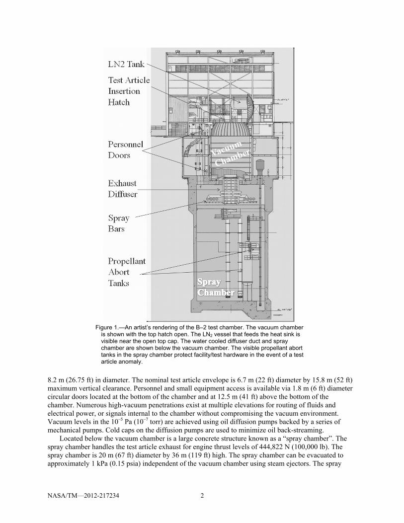
The B–2 test facility is located at Plum Brook Station, in Sandusky, Ohio. Plum Brook Station is the 2590 hectare (6400 acre) field station of NASA Glenn Research Center. The test facilities at Plum Brook are separated by large distances to safely support testing of large quantities of gaseous or cryogenic propellants necessary for rocket engine and component testing. An artist’s rendering of the B–2 Facility is shown in Figure 1.
The center of the B–2 facility is a large vertical vacuum chamber. The chamber consists of a cylindrical section that is 14 m (46 ft) high by 11.5 m (38 ft) topped with a hemispherical head of the same diameter. The lower end of the chamber has a 3.4 m (11 ft) diameter by 11.3 m (37 ft) long exhaust duct sealed with a high vacuum valve. Typical test article installation into the test chamber is via a hinged hatch at the top of the hemispherical dome using an 18,100 kg (20 ton) overhead crane. The hatch is
NASA/TM—2012-217234 2
Figure 1.—An artist’s rendering of the B–2 test chamber. The vacuum chamber
is shown with the top hatch open. The LN2 vessel that feeds the heat sink is visible near the open top cap. The water cooled diffuser duct and spray chamber are shown below the vacuum chamber. The visible propellant abort tanks in the spray chamber protect facility/test hardware in the event of a test article anomaly.
8.2 m (26.75 ft) in diameter. The nominal test article envelope is 6.7 m (22 ft) diameter by 15.8 m (52 ft) maximum vertical clearance. Personnel and small equipment access is available via 1.8 m (6 ft) diameter circular doors located at the bottom of the chamber and at 12.5 m (41 ft) above the bottom of the chamber. Numerous high-vacuum penetrations exist at multiple elevations for routing of fluids and electrical power, or signals internal to the chamber without compromising the vacuum environment. Vacuum levels in the 10–5 Pa (10–7 torr) are achieved using oil diffusion pumps backed by a series of mechanical pumps. Cold caps on the diffusion pumps are used to minimize oil back-streaming.
Located below the vacuum chamber is a large concrete structure known as a “spray chamber”. The spray chamber handles the test article exhaust for engine thrust levels of 444,822 N (100,000 lb). The spray chamber is 20 m (67 ft) diameter by 36 m (119 ft) high. The spray chamber can be evacuated to approximately 1 kPa (0.15 psia) independent of the vacuum chamber using steam ejectors. The spray
NASA/TM—2012-217234 3
chamber is filled with 6.6 million liters (1.75 million gallons) of cooling water. During an engine firing at altitude conditions, the cooling water is circulated to a series of spray bars which produce a fine water spray to quench and condense the exhaust. Non-condensable components are exhausted via the steam ejectors. Cooling is also provided on the back side of the diffuser duct and to the steam ejectors. Fuel and oxidizer abort (dump) tanks are also located in the spray chamber and can be used to safe the facility in the event of a test article anomaly.
Thermal simulation for the test article is achieved using a liquid nitrogen heat sink and an infrared lamp array. The interior surface of the stainless steel vacuum chamber is lined with a liquid nitrogen (LN2) heat sink or cold wall. The heat sink covers the entire interior of the test chamber reducing the internal clearance to 10.4 m (34 ft) diameter and 17 m (56 ft) high. The access hatch or top cap has a separate liquid nitrogen heat sink. The only portion of the chamber not having integrated heat sink coverage is a 6.7 m (22 ft) diameter circle on the floor level of the chamber. The heat sink consists of a series of finned tubes connected to an upper and lower manifold. The fins are arranged parallel to the chamber wall resulting in an optically dense surface. The heat sink is flooded with LN2 providing a background temperature of 77 K (140 °R). The heat sink is constructed of copper to optimize conduction. An infrared lamp array installed in the vacuum chamber provides a heat flux pattern equivalent to a nominal solar constant, 1.367 kW/m2. The array is configurable and can be independently controlled by twelve (12) zone controllers. When fully configured, each zone contains forty-eight (48) 0.75 kW lamps resulting in a total array power of 432 kW. Each zone controller is rated at 50 kW yielding a system capacity of 600 kW. When the heat sink and infrared lamp array are used simultaneously, a test article can be exposed to a thermal pattern representing deep space on one surface and the solar expose on a separate surface.
The test building is designed for propellant testing. Components in the building have been selected to be non-incendiary or are located in purged/pressurized enclosures. During propellant testing, personnel are evacuated from the test building. Tests are conducted from a remote control room located 777 m (2,550 ft) west of the test building.
Propellants are stored in bulk outside of the test building. On-site liquid hydrogen (LH2) storage capacity is 128,704 L (34,000 gal). B–2’s storable fuel (fuel which is liquid at ambient temperatures) storage capacity is 24,605 L (6500 gal). The liquid oxygen (LO2) storage capacity is 45,425 L (12,000 gal). Gaseous nitrogen (GN2) and gaseous helium (GHe) are used to provide purge and pressurization.
Decades of Testing
The B–2 test facility was designed to test upper stage vehicles and engines at simulated altitude conditions. The size and capabilities of the thermal vacuum chamber in addition to the ability to simultaneously test fuels and oxidizers has pushed B–2 outside of its original mission of testing upper stage vehicles.
During the development of the Centaur vehicle approximately 73 tests were performed at B–2 (Ref. 1). Some of the Centaur development tests involved tanking and chilldown leading up to ignition and restart testing and finally full duration mission simulation tests. Upper stage test capabilities were also used during the Delta III (Ref. 2) programs in the 1990s. The B–2 vacuum chamber was also used to develop engine chill down techniques for both the Atlas Reliability Enhancement Program (AREP) (Ref. 3) and Delta III Programs (Ref. 2). Altering the chill down for the engines led to lower over board propellant losses leading to enhanced payload capability.
B–2 has also been involved in development of small thrusters, payloads, and components for use in upper atmosphere and space environments. In small thruster test programs the facility exhaust systems are not used. After the vacuum chamber has reached altitude conditions, the thruster is fired for short durations. Due to the size of the vacuum chamber, pressures do not increase significantly. Thruster programs have included Pulse Detonation Rocket Engine (PDRE). Arcjet plume interaction with solar arrays was also studied in the vacuum chamber (Ref. 4). Ground testing of payloads in the B–2 chamber

NASA/TM—2012-217234 4
Figure 2.—Centaur Stage (left) and TRACER test package (right) positioned over
B–2 Vacuum Chamber. has provided valuable information. The information gained by testing in a thermal vacuum chamber has contributed to mission successes. Sounding rocket experimental payloads that were pre-flight tested at B–2 to confirm operation under vacuum and to calibrate systems include Space Powered Experiments Aboard Rockets (SPEAR) (Ref. 5) and Excitation by Electron Deposition (EXCEDE). For similar reasons, balloon payloads including Transition Radiation Array for Cosmic Energetic Radiation (TRACER) (Ref. 6) and Cosmic Ray Electron Synchrotron Telescope (CREST) have also done pre-flight thermal vacuum testing. The test chamber and cold wall were used for airbag inflation tests for the Mars Pathfinder (Ref. 7) and Mars Exploration Rover (MER) (Ref. 8). Figure 2 shows a Centaur Stage and the TRACER test package positioned over the B–2 vacuum chamber.
The B–2 chamber has also been used for non-aerospace applications such as drying personnel records in the 1970s by cyclically heating and evacuating the chamber. Heating was accomplished by introducing steam rather than LN2 into the heat sink.
B–2 is continuously meeting with customers to discuss testing options that include tanking tests, simultaneous fuel/oxidizer cryogenic fluid management (CFM) tests, and engine tests.
Facility Modernization and Refurbishments
In 2006, an effort to systematically refurbish all major facility subsystems and ancillary infrastructure equipment was started (Ref. 9). The aim of the refurbishment was to modernize the facility in phases starting with the vacuum system and proceeding to the thermal simulation system and then the cryogenic propellant and exhaust systems. The facility data acquisition and controls systems have also undergone extensive modernization.
The vacuum system and test chamber were completely refurbished. All vacuum pumps were completely rebuilt. In addition to replacing the existing instrumentation, additional health monitoring and diagnostic instruments were installed. The chamber was extensively leak checked and non-destructive evaluation was performed to verify the structural integrity of the vacuum chamber and system. The thermal simulation system was also refurbished. Non-destructive evaluation of the heat sink and the LN2 supply and vent lines was performed. The controllers for the infrared lamp array were replaced with state of the art systems. Following the completion of refurbishment of the thermal simulation system, an integrated systems test was conducted to demonstrate performance.

NASA/TM—2012-217234 5
Figure 3.—Modernized Control Room for B–2. Graphical user
interfaces (GUI) for the programmable logic control (PLC) based system are visible in the foreground. Along the back wall, video monitors display test site camera images. The independent data system consoles are not shown in this view.
The facility control system was completely replaced in 2006 with a state of the art programmable logic control (PLC) based system. Graphical user interfaces (GUI) are used for operations. The control system is used to monitor facility systems and keeps a log of key parameters. The control system was designed to be easily reconfigured to support specific test package requirements. Cabling between the control room and test facility has been replaced with a fiber optic network. Remote video monitoring of the test facility was also upgraded. The data acquisition system is separate from the control systems. Data is time synchronized with the control system using an IRIG-B protocol. The test data is digitized in a data room at the test facility and is immediately transmitted to data recording units located in the control room. The fiber optic network has been designed to minimize time delays between data acquisition at the test site and transmission to the control room. Currently there are 488 channels of low speed, 32 channels of high speed, and 64 channels of discrete input in the data system. The data system can acquire data up to 4,000 samples per second in the low speed and up to 256,000 samples per second in high speed. Slower sampling rates are also achievable and are set typically at 125 samples per second. After the data has been recorded, it is post processed for customer review. Figure 3 shows the modern control room for B–2.
Refurbishment of the LH2 and GHe system are on-going. Plans have been developed for the renewal of the LO2 and exhaust systems.
Thermal Vacuum Integrated System Test
For the thermal vacuum integrated system test, a simulated test article was located approximately 3.7 m (12 ft) above the vacuum chamber floor. Three (3) zones of infrared lamps were installed. A vacuum level of 9×10⁻⁴ Pa was achieved rather than the rated 10–5 Pa due to a leak in a camera purge. During the test, heat flux equivalent to one solar constant was measured at the test article. The lamp arrays were operated using both open and closed loop control. Fine tuning of the heat flux was demonstrated by controlling the power input to the lamp arrays. The arrays were operated both with and without the heat sink (body and top cap) filled with LN2. When the heat sink is at 77 K, slightly more power is required to achieve the same heat flux at the test article. Steady state temperature readings were

NASA/TM—2012-217234 6
Figure 4.—In the foreground of the picture is a test article designed
to represent the rounded wall of a tank. Visible in the background are 3 infrared lamp arrays.
achieved approximately 5 hr after filling the heat sink. (It should be noted that the simulated test article reached steady state temperature quickly due to the lack of insulation.) See Figure 4 for a picture of the simulated test article installed in the vacuum chamber.
Conclusions
The B–2 facility was originally designed as a thermal vacuum facility to test upper stages over the entire operational life including engine operation at altitude conditions. Over the years, the facility has been used for other tests requiring vacuum, thermal vacuum, or altitude-engine operations. Strategic investments have been made to modernize and refurbish facility systems and infrastructure. A recently completed thermal vacuum integrated systems test demonstrated the successful operation of the newly refurbished systems. Plans for continued investment in the propellant and exhaust systems will result in a fully revitalized facility.
References
1. Grosbeck, W., Baud, K., Lacovic, R., Tabata, W., and S. Szabo, “Propulsion System Tests on A Full Scale Centaur Vehicle to Investigate 3-Burn Mission Capability of the D-1T Configuration,” NASA TM X-71511.
2. Meyer, M., Dickens, K., Skaff, A., Cmar, M., VanMeter, M., and Haberbusch, M., “Performance of Spacecraft Propulsion Research Facility During Altitude Firing Tests of the Delta III Upper Stage,” NASA TM-1998-208477.
3. Schuster, J., Howell, D, Lucas, S., Haberbusch, M., Gaby, J., Van Dresar, N., and Wadel, M., “Cold Flow Testing of Revised Engine Chilldown Methods for the Atlas Centaur,” AIAA 96-3014.

NASA/TM—2012-217234 7
4. Galofaro, J., Vayner, B., Hillard, G., and Chornak, M., “Thruster Plume Plasma Diagnostics: A Ground Chamber Experiment for a 2-Kilowatt Arcjet,” NASA TM-2005-213837.
5. Rochefort, J., O’Connor, L., Sukys, R., Poirier, N., and Morin, R., “Instrumentation, Control, and Communication Systems for Sounding Rockets and Shuttle-Borne Experiments,” PL TR 91-2175.
6. Muller, D., “Status,” TRACER home page, http://tracer.uchicago.edu/status.html, date accessed May 13, 2011.
7. Cadogan, D., Sandy, C., and Grahne, M., Acta Astronautica, 50, pp. 633-640 (2002). 8. Stein, J. and Sandy, C., “Recent Developments in Inflatable Airbag Attenuation Systems for Mars
Exploration,” AAF-061. 9. Hill, G., Weaver, H., Kudlac, M., Evans, R., and Maloney, C., “Space Propulsion Research Facility
(B–2) An Innovative, Multi-Purpose Test Facility,” Aerospace Testing Seminar 2011.

REPORT DOCUMENTATION PAGE Form Approved
OMB No. 0704-0188 The public reporting burden for this collection of information is estimated to average 1 hour per response, including the time for reviewing instructions, searching existing data sources, gathering and maintaining the data needed, and completing and reviewing the collection of information. Send comments regarding this burden estimate or any other aspect of this collection of information, including suggestions for reducing this burden, to Department of Defense, Washington Headquarters Services, Directorate for Information Operations and Reports (0704-0188), 1215 Jefferson Davis Highway, Suite 1204, Arlington, VA 22202-4302. Respondents should be aware that notwithstanding any other provision of law, no person shall be subject to any penalty for failing to comply with a collection of information if it does not display a currently valid OMB control number. PLEASE DO NOT RETURN YOUR FORM TO THE ABOVE ADDRESS.
1. REPORT DATE (DD-MM-YYYY) 01-12-2012
2. REPORT TYPE Technical Memorandum
3. DATES COVERED (From - To)
4. TITLE AND SUBTITLE NASA Plum Brook’s B-2 Test Facility: Thermal Vacuum and Propellant Test Facility
5a. CONTRACT NUMBER
5b. GRANT NUMBER
5c. PROGRAM ELEMENT NUMBER
6. AUTHOR(S) Kudlac, Maureen, T.; Weaver, Harold, F.; Cmar, Mark, D.
5d. PROJECT NUMBER
5e. TASK NUMBER
5f. WORK UNIT NUMBER WBS 750271.09.02.03
7. PERFORMING ORGANIZATION NAME(S) AND ADDRESS(ES) National Aeronautics and Space Administration John H. Glenn Research Center at Lewis Field Cleveland, Ohio 44135-3191
8. PERFORMING ORGANIZATION REPORT NUMBER E-17933
9. SPONSORING/MONITORING AGENCY NAME(S) AND ADDRESS(ES) National Aeronautics and Space Administration Washington, DC 20546-0001
10. SPONSORING/MONITOR'S ACRONYM(S) NASA
11. SPONSORING/MONITORING REPORT NUMBER NASA/TM-2012-217234
12. DISTRIBUTION/AVAILABILITY STATEMENT Unclassified-Unlimited Subject Category: 31 Available electronically at http://www.sti.nasa.gov This publication is available from the NASA Center for AeroSpace Information, 443-757-5802
13. SUPPLEMENTARY NOTES
14. ABSTRACT The National Aeronautics and Space Administration (NASA) Glenn Research Center (GRC) Plum Brook Station (PBS) Spacecraft Propulsion Research Facility, commonly referred to as B-2, is NASA’s third largest thermal vacuum facility. It is the largest designed to store and transfer large quantities of liquid hydrogen and liquid oxygen, and is perfectly suited to support developmental testing of upper stage chemical propulsion systems as well as fully integrated stages. The facility is also capable of providing thermal-vacuum simulation services to support testing of large lightweight structures, Cryogenic Fluid Management (CFM) systems, electric propulsion test programs, and other In-Space propulsion programs. A recently completed integrated system test demonstrated the refurbished thermal vacuum capabilities of the facility. The test used the modernized data acquisition and control system to monitor the facility. The heat sink provided a uniform temperature environment of approximately 77 K. The modernized infrared lamp array produced a nominal heat flux of 1.4 kW/m2. With the lamp array and heat sink operating simultaneously, the thermal systems produced a heat flux pattern simulating radiation to space on one surface and solar exposure on the other surface. 15. SUBJECT TERMS Vacuum; Vacuum chamber; Solar constant; Thermal simulation; Cryogenic fluids; Heat sink; Test facility; Propellants
16. SECURITY CLASSIFICATION OF: 17. LIMITATION OF ABSTRACT UU
18. NUMBER OF PAGES
14
19a. NAME OF RESPONSIBLE PERSON STI Help Desk (email:[email protected])
a. REPORT U
b. ABSTRACT U
c. THIS PAGE U
19b. TELEPHONE NUMBER (include area code) 443-757-5802
Standard Form 298 (Rev. 8-98)Prescribed by ANSI Std. Z39-18

