nasa dryden status · nasa dryden status ... this presentation provides a desciption of the current...
TRANSCRIPT

ACGSC Meeting 109, March 2012
NASA Dryden Status
Aerospace Control & Guidance Sub-committee
Meeting 109
Salt Lake City, UT
March 2012
Steve Jacobson
(661) 276-7423
https://ntrs.nasa.gov/search.jsp?R=20120011468 2018-06-29T00:16:29+00:00Z

ACGSC Meeting 109, March 2012
Abstract
NASA Dryden has been engaging in some exciting work that will enable lighter weight and more fuel efficient vehicles through advanced control and dynamics technologies. The main areas of emphasis are “Enabling Light-weight Flexible Structures”, real time control surface optimization for fuel efficiency and autonomous formation flight. This presentation provides a desciption of the current and upcoming work in these areas. Additionally, status is for the Dreamchaser pilot training activity and autonomous aerial refueling of the Global Hawk UAS’s.
ACGSC Meeting 109, March 2012
Enabling Light Weight Flexible Structures
Develop algorithms, sensors and architectures to enable static shape and dynamic control of light weight flexible aerostructures
• Multi-Utility Technology Testbed (MUTT)
• Advanced Sensors for controlling flexible structures
•Modeling, Simulation and Control
ACGSC Meeting 109, March 2012
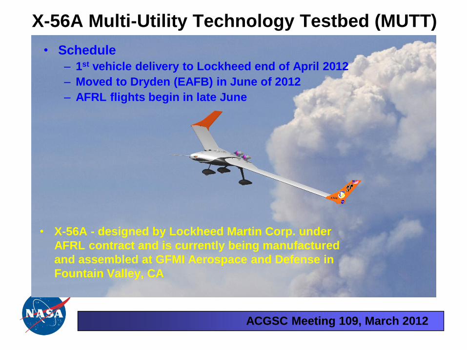
• Schedule
– 1st vehicle delivery to Lockheed end of April 2012
– Moved to Dryden (EAFB) in June of 2012
– AFRL flights begin in late June
X-56A Multi-Utility Technology Testbed (MUTT)
• X-56A - designed by Lockheed Martin Corp. under
AFRL contract and is currently being manufactured
and assembled at GFMI Aerospace and Defense in
Fountain Valley, CA
ACGSC Meeting 109, March 2012
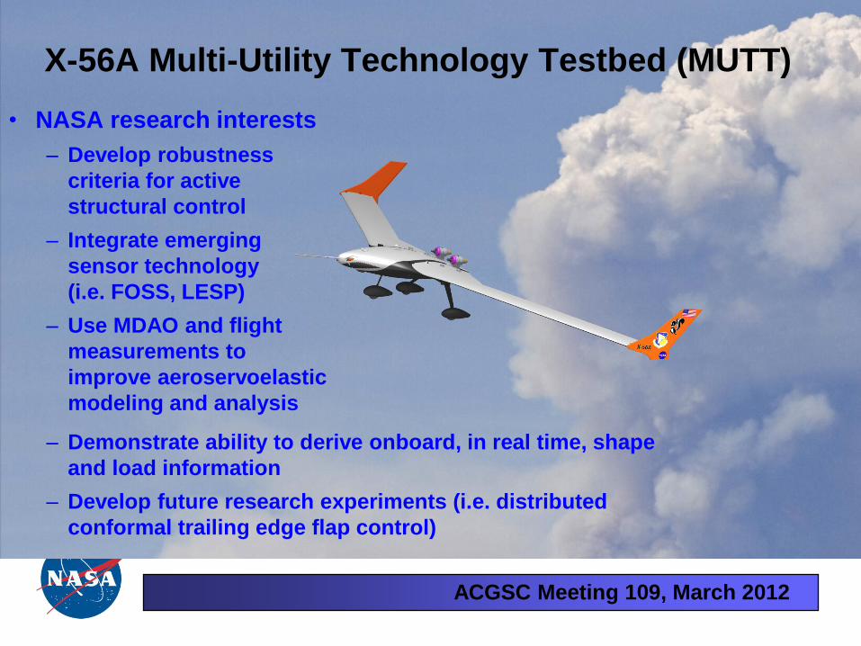
• NASA research interests
– Develop robustness
criteria for active
structural control
– Integrate emerging
sensor technology
(i.e. FOSS, LESP)
– Use MDAO and flight
measurements to
improve aeroservoelastic
modeling and analysis
X-56A Multi-Utility Technology Testbed (MUTT)
– Demonstrate ability to derive onboard, in real time, shape
and load information
– Develop future research experiments (i.e. distributed
conformal trailing edge flap control)
ACGSC Meeting 109, March 2012
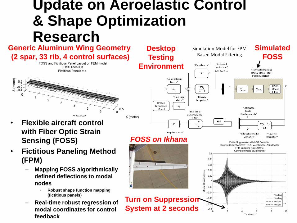
Update on Aeroelastic Control & Shape Optimization Research
• Flexible aircraft control
with Fiber Optic Strain
Sensing (FOSS)
• Fictitious Paneling Method
(FPM) – Mapping FOSS algorithmically
defined deflections to modal
nodes • Robust shape function mapping
(fictitious panels)
– Real-time robust regression of
modal coordinates for control
feedback
Simulated
FOSS Desktop
Testing
Environment
Turn on Suppression
System at 2 seconds
FOSS on Ikhana
Generic Aluminum Wing Geometry
(2 spar, 33 rib, 4 control surfaces)

ACGSC Meeting 109, March 2012
Aeroelastic Research Tool Development
• Simulation environment based on validated development efforts
– Early course corrections
– Easy to test FOSS in user-defined environment
– Understanding aeroelastic phenomena
Flutter Speed
Analysis Capabilities
Flutter
Frequency

ACGSC Meeting 109, March 2012
Fuel savings through optimization
•Intelligent Control for Performance
•Formation Flight

ACGSC Meeting 109, March 2012
Intelligent Control for Performance
• Reduce fuel burn with peak-seeking control.
• In-flight trim optimization of multiple effectors.
• Estimate performance function gradient with a time-varying Kalman filter.
Plant
Performance Function
time-varying Kalman filter
Performance Function Surface
Notional Flight Test Point
Full-scale Advanced Systems Testbed (FAST)
Modified F-18
0 50 100 150 200 250 300 350 400 450
0
0.5
1
1.5
2
2.5
Performance Function Time History
time (sec)
Perf
orm
ance
Fu
nct
ion
Va
lue
Ideal
Run 1
Run 2
Run 3
Run 4
Run 5
Simulation
:
Flight Research Plans
• Install research-grade fuel flow meters
• April: Flight to characterize the performance function
• May: Closed-loop ICP research flights
Time (approx. 10 minute duration)
Fu
el
Flo
w
Baseline aircraft
Initial surface
biases
ICP engaged
Fuel
Savings
ACGSC Meeting 109, March 2012
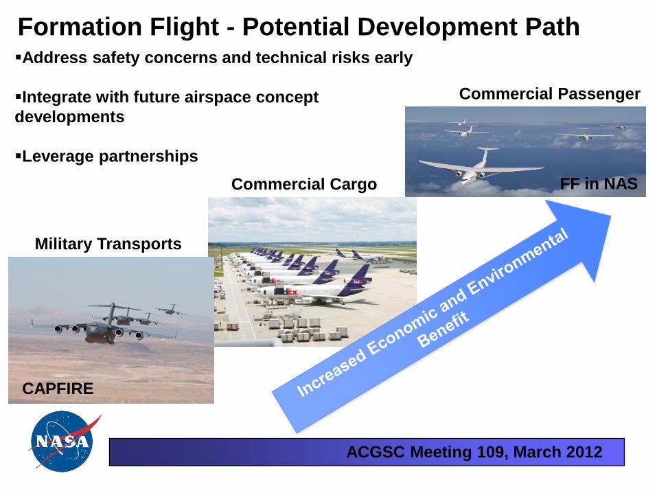
Formation Flight - Potential Development Path
Military Transports
Commercial Cargo
Commercial Passenger
Address safety concerns and technical risks early
Integrate with future airspace concept
developments
Leverage partnerships
CAPFIRE
FF in NAS
ACGSC Meeting 109, March 2012
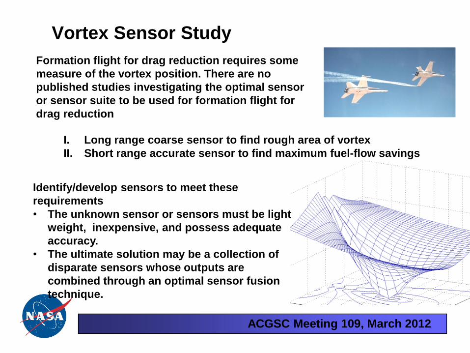
Vortex Sensor Study
Formation flight for drag reduction requires some
measure of the vortex position. There are no
published studies investigating the optimal sensor
or sensor suite to be used for formation flight for
drag reduction
I. Long range coarse sensor to find rough area of vortex
II. Short range accurate sensor to find maximum fuel-flow savings
Identify/develop sensors to meet these
requirements
• The unknown sensor or sensors must be light
weight, inexpensive, and possess adequate
accuracy.
• The ultimate solution may be a collection of
disparate sensors whose outputs are
combined through an optimal sensor fusion
technique.

ACGSC Meeting 109, March 2012
Status on other work

ACGSC Meeting 109, March 2012
F-18 FAST
2012 work
• Expand the Class B software envelope from 350 KCAS to 300+ knots and lower elevations
• Allows for approach and landing experiments without touchdown
• In flight simulator training
• Integrating Leading Edge Stagnation Point Sensor (Tau Systems) for performance evaluation as a feedback sensor
• Intelligent Control for Performance Research

ACGSC Meeting 109, March 2012
23 6
Dryden Approach Utilize an F/A-18 as an in-flight simulation of the Sierra Nevada Corporation’s Dream Chaser, modeling both the rigid body dynamics and the energy properties for piloted approach and landing tests (glide phase)
Customer Need (SNC) A high fidelity, low risk, low cost flight environment to: 1. Evaluate the predicted handling qualities of the Dream Chaser vehicle 2. Provide pilot training prior to initial piloted glide and rocket born flights of the actual vehicle
FAST Aircraft to be used for Approach
and Landing Test Support for the
Dream Chaser Commercial Crew
Concept
ACGSC Meeting 109, March 2012
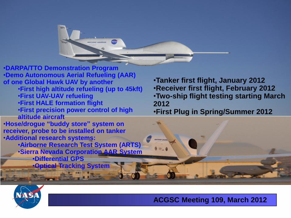
•Tanker first flight, January 2012 •Receiver first flight, February 2012 •Two-ship flight testing starting March 2012 •First Plug in Spring/Summer 2012
•DARPA/TTO Demonstration Program •Demo Autonomous Aerial Refueling (AAR) of one Global Hawk UAV by another
•First high altitude refueling (up to 45kft) •First UAV-UAV refueling •First HALE formation flight •First precision power control of high altitude aircraft
•Hose/drogue “buddy store” system on receiver, probe to be installed on tanker •Additional research systems:
•Airborne Research Test System (ARTS) •Sierra Nevada Corporation AAR System
•Differential GPS •Optical Tracking System
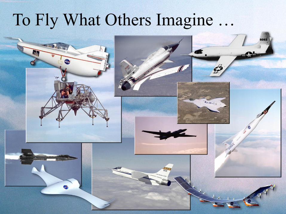
To Fly What Others Imagine …
ACGSC Meeting 109, March 2012
Backup charts

ACGSC Meeting 109, March 2012
Optimized Lift for Autonomous Formation Flight (OLAFF)
• Experimental in-flight evaluations have shown that the concept of
formation flight can reduce fuel use by 10-15%
• Additional drag reduction can be achieved
by increasing wing loading near the
wingtip immersed in the vortex
(Iglesias, 2000 and Hanson, 2009)
-10 -5 0 5 1070
75
80
immersed aileron, deg
J =
f(d
rag)
initial
final
Cost Function
Solutions
Δ induced drag
original
lift vector
rotated
lift vector
free stream velocity
net induced
upwash angle
free stream
angle-of-attack
wake downwash
vortex upwash
induced drag
original local velocity
rotated local velocity
• The objective of OLAFF is to apply peak-seeking
control technology to the real-time adjustment of
the aileron and flap of the immersed wing for
optimal drag
• Low TRL activity that could
eventually lead to validation
through flight research
ACGSC Meeting 109, March 2012
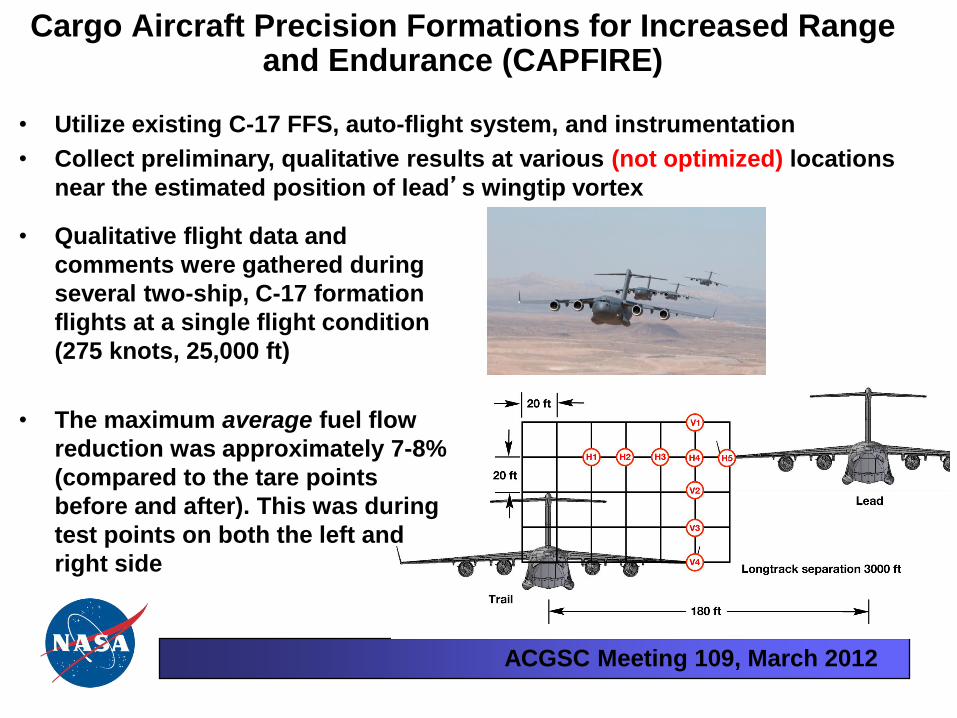
Cargo Aircraft Precision Formations for Increased Range and Endurance (CAPFIRE)
• Utilize existing C-17 FFS, auto-flight system, and instrumentation
• Collect preliminary, qualitative results at various (not optimized) locations
near the estimated position of lead’s wingtip vortex
• Qualitative flight data and
comments were gathered during
several two-ship, C-17 formation
flights at a single flight condition
(275 knots, 25,000 ft)
• The maximum average fuel flow
reduction was approximately 7-8%
(compared to the tare points
before and after). This was during
test points on both the left and
right side

ACGSC Meeting 109, March 2012
Formation Geometry for Flight Test
~ 18 wing spans
3000 ft
Not to scale
Approximately to scale