nasa contractor ~.. nia report · nasa contractor report study of ... for atmosphere braking to...
TRANSCRIPT

"
. . ,"
N A S A C O N T R A C T O R
R E P O R T
STUDY OF TECHNOLOGY REQUIREMENTS FOR ATMOSPHERE BRAKING TO ORBIT ABOUT MARS AND VENUS
Volume I - Summary
Prepared by NORTH AMERICAN ROCKWELL CORPORATION Downey, Calif. for Ames Research Center
~.. NIA
N A T I O N A L A E R O N A U T I C S A N D S P A C E A D M I N I S T R A T I O N WASHINGTON, D . C. SEPTEMBER 1968
https://ntrs.nasa.gov/search.jsp?R=19680024614 2018-07-06T15:06:06+00:00Z

w NASA CR-1131
/- - / J
/
STUDY OF TECHNOLOGY REQUIREMENTS FOR
ATMOSPHERE BRAKING TO ORBIT y a. e
BOUT MARS AND VENUS 1 4 b ' -.
Distribution of this report is provided in the interest of information exchange. Responsibility for the contents resides in the author or organization that prepared it.
/ SD 67-994- 1" 9
,/Prepared under Contract No. NAS 2-4135 by NORTH AMERICAN ROCKWELL CORP-
Downey , Calif . for Ames Research Center
NATIONAL AERONAUTICS AND SPACE ADMINISTRATION - " - . - ~ ". .. .. For sa le by the Clearinghouse for Federal Scientif ic and Technical Information
Springfield, Virginia 22151 - CFSTI price $3.00

FOREWORD
This volume presents a condensed summary of the study. It is being submitted in accordance with Paragraph 2. 6 of Specification A-12241 contained in Contract NAS2-4135, Study of Technology Require- ments for Atmosphere Braking to Orbit About Mars and Venus, which was issued by the Mission Analysis Division, National Aeronautics and Space Adminis- tration. The data were generated between January and October 1967 and are presented in three volumes:
Volume I - Summary (SD67-994- 1)
Volume I1 - Technical Analyses (SD 67-994-2)
Volume I11 - Appendices (SD 67-994-3)
Volume IV - Final Briefing (SD 67-994-4)

CONTENTS
Section
1 .0 INTRODUCTION . 2. 0 STUDY GUIDELINES AND SCOPE . 3 . 0 AEROBRAKING MISSION-SYSTEM DESCRIPTION
4. 0 SIGNIFICANT RESULTS . 4. 1 Aerobraking Vehicle Requirements . 4. 2 Configuration Analysis . 4. 3 Recommended Configurations . 4. 4 Sensitivity Analyses 4. 5 Modular Approach to Vehicle Synthesis 4. 6 Test and Qualification Considerations .
5. 0 RELATIONSHIP TO OTHER NASA PROGRAMS .
6. 0 SUGGESTIONS FOR FUTURE WORK . 6. 1 Planetary-Capture Mission-System Analyses 6. 2 Atmosphere-Braking-Vehicle Technology Studies
Page
1
4
6
9 9
12 16 17 20 21
21
22 22 2 3
- v -

ILLUSTRATIONS
Figure Page
1 2 3 4 5 6 7 8 9
10 11
12 13 14
Mars Aerobraking Maneuver . Initial Mass in Earth Orbit - Mars Missions Initial Mass in Earth Orbit - Venus Missions Study Logic Diagram . Flared-Cone Concept . Mars and Venus Parking-Orbit Characteristics Mars Aerobraker Miss'ion Profile . Spacecraft Configurations . Effect of Orbit Eccentricity on Vehicle Weight Lift-to-Drag Ratio Requirements . Effect of m/C+ and Analytical Model on M a r s
Effect of Entry Velocity on Heatshield Weight Heatshield Weight Breakdowns . Modular Approach to Aerobraker Synthesis .
Aerobraker Stagnation-Point Heating .
1 2 2 3 4 6 7 7
10 10
11 12 17 20
TABLES
Table Page
1 Entry Parameters . 4 2 Mission Trip Times . 5 3 Mars Orbiter Mission Vehicles 1 3 4 Mars Lander Mission Vehicles 13 5 Venus Orbiter Mission Vehicles . 14 6 Module Shape Variations . 14 7 Aerobraker Spacecraft Weight Sensitivities . 18
- vii -
" . . . . . ~ .

1 . 0 INTRODUCTION
Manned missions to Mars and Venus, although not a stated national goal , are a logical extension of the current space program. Overall technical feasibility of such mis- sions appears within the current and projected near-term state of the a r t . However, the eventual accomplish- ment is constrained by certain key issue? which must be resolved in the early planning phases. One key decision which must be made early in the program involves the choice of the mode to effect planet capture (i. e . , retrobraking or aerobraking). Each mode obviously must be studied intensively to develop the requisite background data for a
I 1000 KM ALTITUDE
APO PLANET OF SPACECRAFT
l l SPIRAL MANEUVER
-*.. V. .., -._ / D-
rational selection at the earliest date.
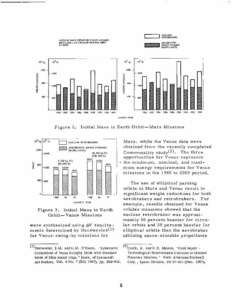
Previous studies have shown that atmosphere braking to orbit about Mars and Venus (shown schemat- ically in Figure 1) offers the poten- tial of significantly lower gross system weights in Earth orbit as compared to retropropulsive cap- ture. Weight comparisons for aerobrakers using space-storable propellants for planet-orbit depar- ture and all nuclear retrobrakers a r e shown in Figures 2 and 3 for Mars and Venus mission opportuni- t ies from 1980 to 2000. Both orbiter and lander missions which are shown
SPACECRAFT RETRACTS ALL EXTERNAL EQUIPMENT AND ASSUMES ATTITUDE FOR ENTRY INTO MARS
/ SPACECRAFT FIRES /Q.""
,
SPACECRAFT HALTS SPIN
ALL EXTERNAL EQUIPMENT SPACECRAFT RETRACTS
AND ASSUMES ATTITUDE FOR ENTRY INTO MARS
. -. - - - -
Figure 1. Mars Aerobraking Maneuver
1
800 km (430 n mi) CIRCULAR PARKING ORBIT NUCLEAR EARTH DEPARTURE STAGES ASSUMED
AT MARS AEROBRAKERS (SPACE STORABLE PROPELLANTS)
2 4 w Z r
IO3 kg
I200
2 BO 3
m
0
1 IO3 Ib n
1980 I982 1984 1986 1988 19W 1993 1995 IW9 1980 I982 1984 1986 1988 1990 1W3 1995 1999
LAUNCH YEAR
Figure 2. Initial Mass in Earth Orbit-Mars Missions
IO3 Ib 0 NUCLEAR RETROBRAKERS Mars, while the Venus data were
PROPELLANTS) AEROBRAKERS (SPACE-STORABLE obtained from the recently completed
-24M) 45.400 kg P/L Commonality study(2). The three (100.000 Ib) opportunities for Venus represent
8 the minimum, nominal, and maxi- mum energy requirements for Venus missions'in the 1980 to 2000 period.
The use of elliptical parking orbits at Mars and Venus result in
- significant weight reductions for both 1988 9 0 91 1988 90 91
LAUNCH YEAR aerobrakers and retrobrakers. For example, results obtained for Venus
Figure 3 . Initial Mass in Earth orbiter missions showed that the Orbit-Venus Missions nuclear retrobraker was approxi-
mately 50 percent heavier for circu- were synthesized using AV require- lar orbits and 20 percent heavier for ments determined by Deerwester(1) elliptical orbits than the aerobraker for Venus-swing-by missions for utilizing space -storable propellants
( l b e r w e s t e r , J. M. and S.M. D'Haem. "Systematic (2)Codik, A . and R. D. Meston, "Final Report - Comparison of Venus Swingby Mode With Standard Technological Requirements Common to Manned Mode of Mars Round Trips. " Journ. of Spacecraft Planetary Missions. " North American Rockwell and Rockets. Vol. 4 No. 7 (July 1967). pp. 904-912. Corp., Space Division, SD 67-621 (Dec. 1967).
2
for all possible mission years. The aerobraking maneuver is potentially more complex than the retrobraking maneuver, however , and the space- craft designs contemplated are more than an order of magnitude larger in mass and volume than the largest entry vehicles yet considered. Potential technology problems in the fields of gasdynamics ,-thermodynam- i c s , s t ruc tu resand ma te r i a l s , and guidance and control could possibly negate some of the indicated weight savings; additionally, no serious consideration has previously been given to the problems of system tes t and qualification.
c _
The primary objective of this study was to conduct a detailed investigation of integrated aerobrak- ing spacecraft and the associated technology implications s o that both -
ITUDIOBJECllVES
. CONFlGUlUllON
the advantages and disadvantages of this mode could be evaluated. Included were parametric and con- ceptual design studies to define the spacecraft weights and their sensi" tivity to variations in the environ- mental models assumed , crew s ize , mission profile, propellants , etc. , as well as internal packaging arrangements. A secondary objec- tive was to analyze the requirements for system simulation, testing, and qualification.
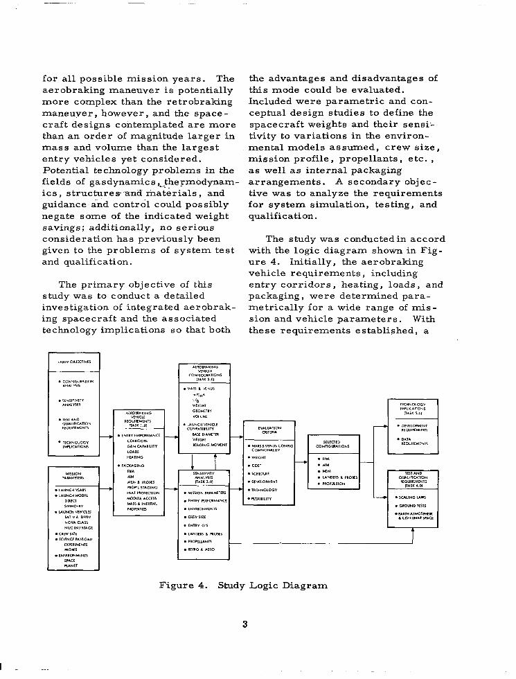
The study was conductedin accord with the logic diagram shown in Fig- u r e 4. Initially, the aerobraking vehicle requirements, including en t ry cor r idors , heating, loads, and packaging, were determined para- metrically for a wide range of m i s - sion and vehicle parameters. With these requirements established, a
. DtMLOPMlNI REQUIREMENTS
DAlA R~QUIREMfNlS
lEQUlREMENlS
. SCALING U W S . GlOUND ltS1S
E U l H A IMOSWEI 6 CIS-LUNAR SPACE
PROfElUNlS I
RfIRO 6 A t R 0
Figure 4. Study Logic Diagram
3
I . ..
configuration analysis was initiated. Concurrently, sensitivity analyses were conducted to establish the effects of variations in mission parameters, propellant selection, and module selection on the vehicle designs. Over 30 detailed designs were generated and evaluated on comparative performance, size, weight, and technology requirements. In the final phase, the four most attractive configurations were
selected, and the technology impli- cations associated with each were delineated. In addition, preliminary consideration was given to test and qualification requirements. The per t inent resul ts are summarized in this volume; more detailed analyses are presented in the volumes entitled, Technical Analyses and Appendices, SD 67-994-2 and 67-994-3.
2 . 0 STUDY GUIDELINES AND SCOPE
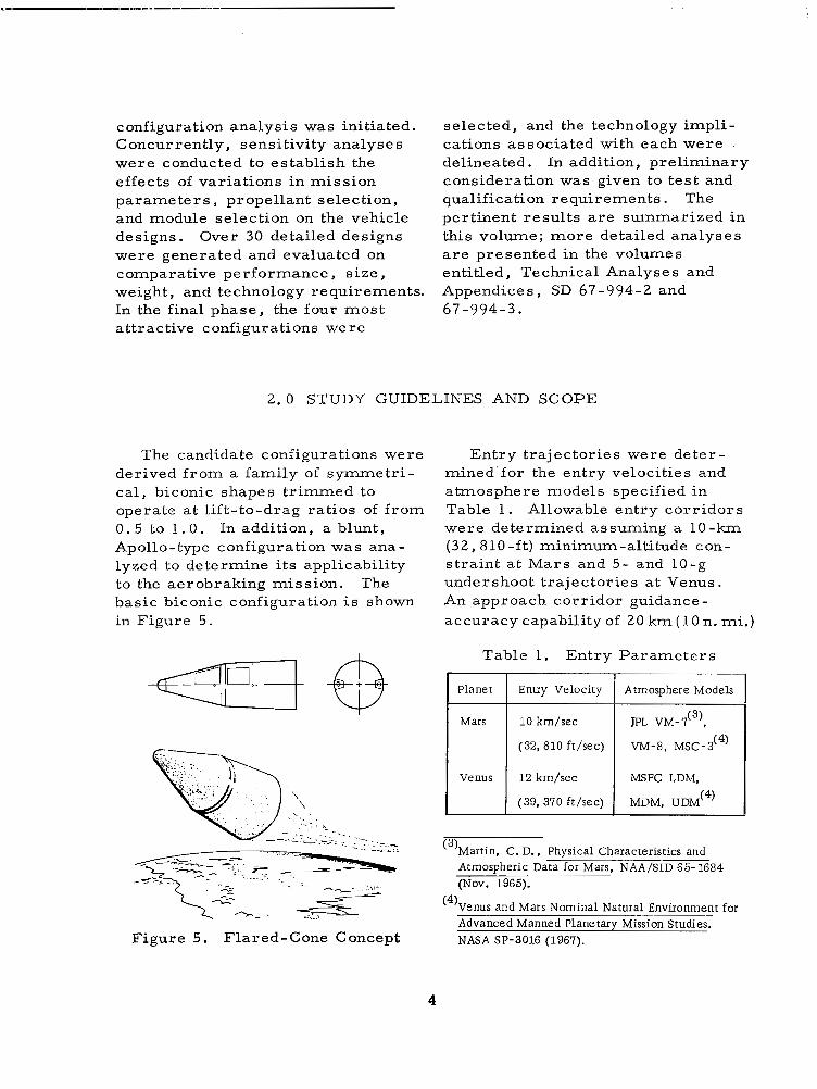
The candidate configurations were derived from a family of s y m e t r i - cal, biconic shapes trimmed to operate at lift-to-drag ratios of f rom 0 . 5 to 1 .0 . In addition, a blunt, Apollo-type configuration was ana- lyzed to determine its applicability to the aerobraking mission. The basic biconic configuration i s shown in Figure 5.
Figure 5. Flared-Cone Concept
Entry trajectories were deter- mined'for the entry velocities and atmosphere models specified in Table 1. Allowable entry corridors were determined assuming a 1 0 - k m (32,810-ft) minimum-altitude con- s t ra int a t Mars and 5- and 10-g undershoot trajectories at Venus. An approach corridor guidance- accuracy capability of 20 km ( 10 n. mi.)
Table 1. Entry Parameters
I Planet I Entry Velocity 1 Atmosphere Models
(32, 810 ft/sec) VM-8, MSC-3 ( 4)
I Venus I 12 km/sec
MDM, UDM (4) (39, 370 ft/sec)
MSFC LDM,
(3)Martin, C. D., Physical Characteristics and Atmospheric Data for Mars, NAA/SID 65- 1684 (Nov. 1965).
(4)Venus and Mars Nominal Natural Environment for W s i o n Studies. NASA SP-3016 (1967).
4
. . .
was assumed. Flow fields and con- vective and radiative heat-transfer rates were determined; nonadiabatic and self-absorption effects were considered. Thermal protection requirements were established using Avcoat 5026 (Apollo material) as the reference ablator .
The entry corridor and heating data were then employed to identify the allowable range of values for the ballistic parameter (m/CDA) and L / D for each atmosphere. Packaging studies were conducted concurrently using these m / C + and L/D require- ments to establish initial geometric relationships and weight distribution requirements for a 10 m (33 ft) base diameter configuration (to be com- patible with the current Saturn V) . A multiloop iteration then was per- formed to establish configurations which were acceptable from both aerodynamic and packaging consid- erations. Structural analyses, including provisions for radiation and meteoroid protection, were con- ducted in support of the packaging studies .
Mission ground rules specified the use of an eight-man crew for both Mars and Venus missions, having four men available at Mars to land an excursion module. The mission module considered for the interplanetary journey was based on the designs developed for the manned Mars fly-by mission(5). The Mars excursion module was obtained from a concurrent study conducted for
("Manned Planetary Flyby Missions Based on Saturn/ Apollo Systems. (Contract NAS8-18025) NAA S&ID, SID 67-549 (1 Aug. 1967).
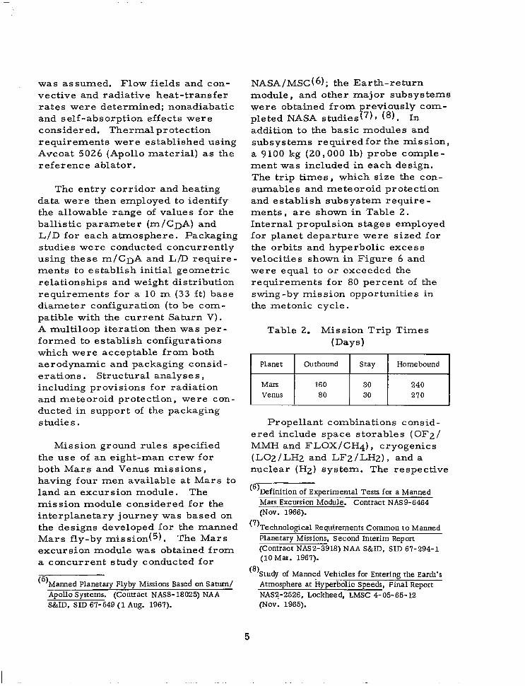
NASA/MSC(6); the Earth-return module, and other major subsystems were obtained from reviously com- pleted NASA studiesr7), ( 8 ) . In addition to the basic modules and subsystems required for the mission, a 9100 kg (20,000 lb) probe comple- ment was included in each design. The trip times, which size the con- s u m a b l e ~ and meteoroid protection and establish subsystem require- men t s , a r e shown in Table 2. Internal propulsion stages employed for planet departure were sized for the orbits and hyperbolic excess velocities shown in Figure 6 and were equal to or exceeded the requirements for 80 percent of the swing-by mission opportunities in the metonic cycle.
Table 2. Mission Trip Times (Days)
I Planet I Outbound I Stay I Homebound 1 1 y::ts 1 80
160 210 30 240 30
Propellant combinations consid- ered include space storables (OF2/ MMH and FLOX/CH4), cryogenics (LO2/LH2 and LFz/LH2), and a nuclear (HZ) system. The respective
(6)Definition of Experimental Tests for a Manned Mars Excursion Module. Contract NAS9-6464 (Nov. 1966).
("Technological Requirements Common to Manned Planetary Missions, Second Interim Report (Contract NAS2-3918) NAA SMD, SID 67-294-1 (10 Mar. 1967).
@)Study -~ of Manned Vehicles for Entering the Earth's Atmosphere at Hyperbolic Speeds, Final Report NAS2-2526, Lockheed, LMSC 4-05-65-12 (Nov. 1965).
5
performance capabilities and pack- aging problems associated with both km/uc 103ft/sec
5.0 bell- and plug-nozzle engines were -- 16.0
B considered. Inasmuch as the tankage
c - nuclear system configurations may
4.0 - s!
requirements for hydrogen-propelled
3.0 - become excessive, other propellants c Y z 5
than hydrogen (e.g., LiH, NH3, e t c . )
advantage accrues from using
tankage requirements (and sizes).
n. 2.0 - were explored to determine i f any VENUS, V, 5.5 km/scc (18, 046 ft/scc)
- 4 . 0 1.0 - higher -density propellants to reduce
I I
0 0.3 0.6 0.9 ECCENTRICITY
VENUS
ORBITAL PERIOD hours
PERIAPSIS ALTITUDE, 3M) km
Figure 6. Mars and Venus Parking- Orbit Characteristics
3.0 AEROBRAKING MISSION-SYSTEM DESCRIPTION
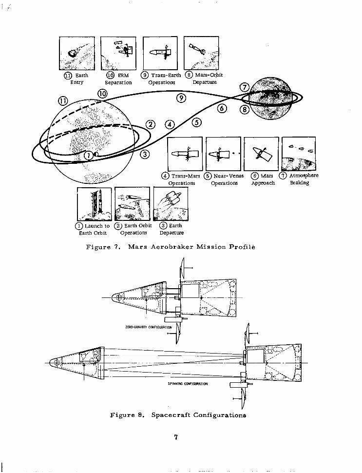
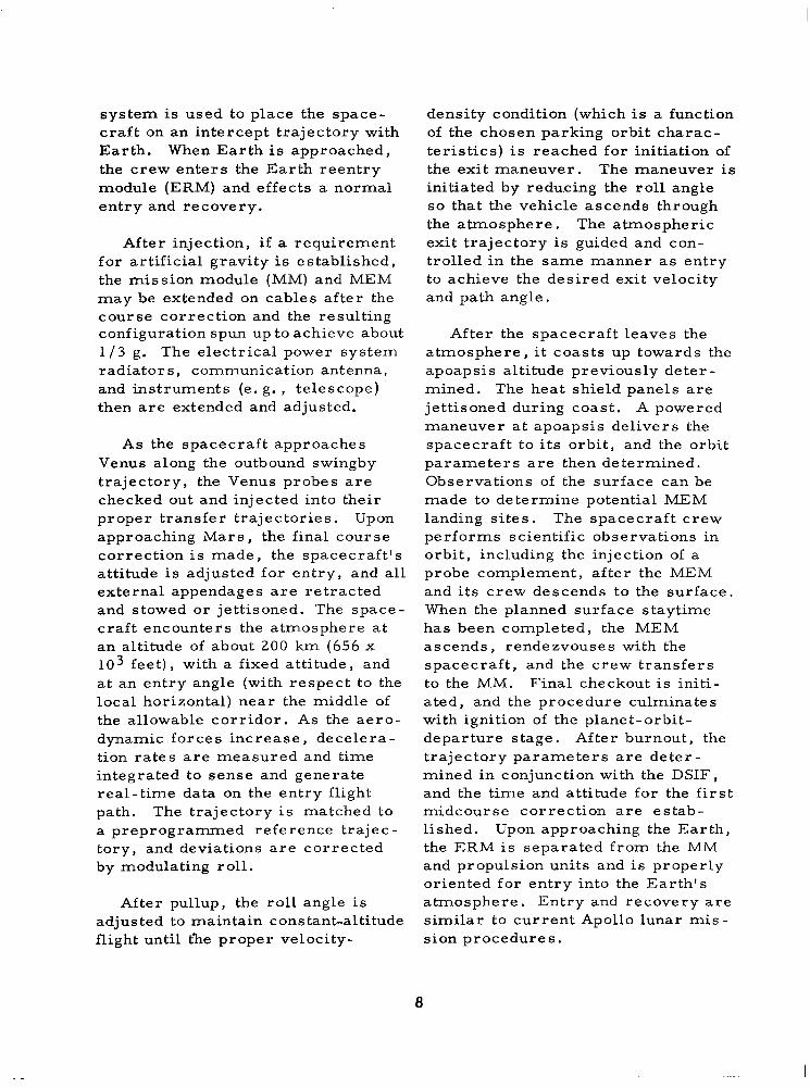
A typical mission profile was developed s o that the various opera- tions and systems involved in a Mars landing mission could be viewed in perspective. The mission is shown schematically in E'igure 7 , and an inboard profile of the aerobraker vehicle is shown in Figure 8. An outbound Venus swing-by mode was chosen, but the profile developed could apply (with minor changes) to either Mars or Venus orbiting or landing missions .
The fully assembled aerobraking vehicle is launched unmanned to an assembly orbit. The crew is deliv- ered to the assembly orbit in a
logistics spacecraft which, presum- ably, has been developed in support of other Earth orbital programs (e. g. , space stations). After the crew is transferred to the aero- braker, injection stages are mated to the vehicle, and rendezvous with the tankers is effected.
The fully fueled and checked-out aerobraker is shown to be injected into a transfer orbit to Mars by nuclear modules. (Two modules may be used for the first-stage injection, a third module being used after the first-stage modules are jettisoned. ) If an abort situation should occur, the Mars-orbit-escape propulsion
6
0 Launch to @ Earth Orbit @) Earth Earth Orbit Operations Departure
Figure 7. Mars Aerobraker Mission Profile
Figure €4. Spacecraft Configurations
system is used to place the space- craft on an intercept trajectory with Earth. When Ear th is approached, the crew enters the Earth reentry module (ERM) and effects a normal entry and recovery.
After injection, i f a requirement for artificial gravity is established, the mission module (MM) and MEM may be extended on cables after the course correction and the resulting configuration spun up to achieve about 1 / 3 g. The electrical power system radiator s , communication antenna, and instruments (e. g . , telescope) then a r e extended and adjusted.
As the spacecraft approaches Venus along the outbound swingby trajectory, the Venus probes a r e checked out and injected into their proper transfer trajectories. Upon approaching Mars, the final course correction is made, the spacecraft 's attitude is adjusted for entry, and all external appendages are retracted and stowed or jettisoned. The space- craft encounters the atmosphere at an altitude of about 200 km (656 x 103 feet), with a fixed attitude, and at an entry angle (with respect to the local horizontal) near the middle of the allowable corridor. As the aero- dynamic forces increase, decelera- tion rates are measured and t ime integrated to sense and generate real-time data on the entry flight path. The trajectory is matched to a preprogrammed reference trajec- tory, and deviations are corrected by modulating roll.
After pullup, the r 011 angle is adjusted to maintain constant-altitude flight until t'he proper velocity-
density condition (which is a function of the chosen parking orbit charac- te r i s t ics ) is reached for initiation of the exit maneuver. The maneuver is initiated by redu.cing the roll angle so that the vehicle ascends through the atmosphere. The atmospheric exit trajectory is guided and con- trolled in the same manner as entry to achieve the desired exit velocity and path angle.
After the spacecraft leaves the atmosphere, i t coasts up towards the apoapsis altitude previously deter- mined. The heat shield panels are jettisoned during coast. A powered maneuver at apoapsis delivers the spacecraft to its orbit, and the orbit parameters are then determined. Observations of the surface can be made to determine potential MEM landing sites. The spacecraft crew performs scientific observations in orbit, including the injection of a probe complement, after the MEM and its crew descends to the surface. When the planned surface staytime has been completed, the MEM ascends, rendezvouses with the spacecraft, and the crew transfers to the MM. Final checkout is initi- ated, and the procedure culminates with ignition of the planet-orbit- departure stage. After burnout, the t ra jec tory parameters a re de te r - mined in conjunction with the DSIF, and the time and attitude for the first midcourse correction are estab- lished. Upon approaching the Earth, the ERM is separated from the MM and propulsion units and is properly oriented for entry into the Ea r th ' s atmosphere. Entry and recovery are similar to current Apollo lunar mis- sion procedures.
a
4 . 0 SIGNIFICANT RESULTS
The study results have shown that the selected aerobraker configura- tions exhibit satisfactory perform- ance and packaging characteristics. There is considerable commonality between the spacecraft systems required to accomplish the Mars and Venus missions i f the parking orbit eccentricity and probe payload parameters are adjusted appropri- ately. This finding resulted in the development of a modular approach to spacecraft design for Mars and/or Venus missions. These areas and other pertinent results are discussed in the paragraphs which follow.
4.1 AEROBRAKING VEHICLE REQUIREMENTS
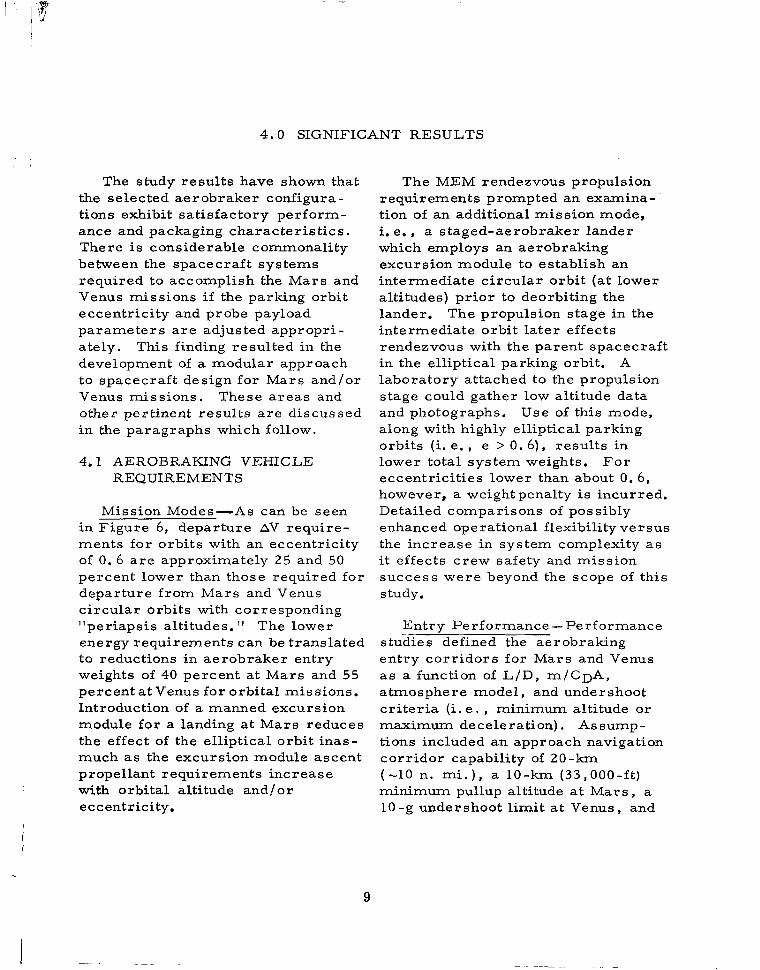
Mission Modes-As can be seen in Figure 6, departure AV require- ments for orbits with an eccentricity of 0 .6 are approximately 25 and 50 percent lower than those required for departure from Mars and Venus circular orbits with corresponding "periapsis altitudes. I ' The lower energy requirements can be translated to reductions in aerobraker entry weights of 40 percent at Mars and 55 percent at Venus for orbital missions. Introduction of a manned excursion module for a landing at Mars reduces the effect of the elliptical orbit inas- much as the excursion module ascent propellant requirements increase with orbital altitude and/or eccentricity.
The MEM rendezvous propulsion requirements prompted an examina- tion of an additional mission mode, i. e. , a staged-aerobraker lander which employs an aerobraking excursion module to establish an intermediate circular orbit (at lower altitudes) prior to deorbiting the lander. The propulsion stage in the intermediate orbit later effects rendezvous with the parent spacecraft in the elliptical parking orbit. A laboratory attached to the propulsion stage could gather low altitude data and photographs, Use of this mode, along with highly elliptical parking orbits (i. e. , e > 0. 6) , results in lower total system weights. For eccentricities lower than about 0. 6, however, a weight penalty is incurred. Detailed comparisons of possibly enhanced operational flexibility versus the increase in system complexity as it effects crew safety and mission success were beyond the scope of this study.
Entry Performance-Performance studies defined the aerobraking entry corridors for Mars and Venus a s a function of L/D, m/CDA, atmosphere model, and undershoot c r i te r ia (i. e . , minimum altitude or maximum deceleration). Assump- tions included an approach navigation corridor capability of 2 0 - k m (-10 n. mi . ) , a 10-km (33,000-ft) minimum pullup altitude at Mars , a 10-g undershoot limit at Venus, and
9
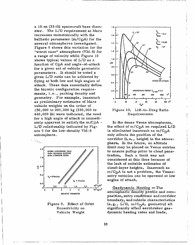
a 10-m (33-ft) spacecraft base diam- eter. The L/D requirement at Mars increases monotonically with the ballistic parameter (m/CDA) for the several atmospheres investigated. Figure 9 shows this variation for the "worst case" atmosphere (VM-8) for a range of velocity while Figure 10 shows typical values of L /D a s a function of CDA and angle -of -attack f o r a given set of vehicle geometric parameters . It should be .noted a given L/D ratio can be achieved by flying a t both low and high angles of attack. These data essentially define the biconic configuration require- ments , i. e . , packing density and geometry. For example , inasmuch
. as preliminary estimates of Mars vehicle weights on the order of 150,000 to 200,000 kg (330,000 to 440,000 lb) were indicated, the need for a high angle of attack is immedi- ately apparent to satisfythe m/CDA - L/D relationship indicated by Fig- u r e 9 for the low-density VM-8 atmosphere.
\. - \
1.2- MODEL ATMOSPHERE VM-8
20-h CORRIDa DEPTH I O - h MINIMUM ALTITUDE
1 .o-
0.6 VE - 10 h/mc
0.4
0 0.5 1 .o 1.5 2.0 10' lb/it2
0 2 4 8 10 IO3 te /m2
BALLISTIC PARAMETER
Figure 9. Effect of Orbit Eccentricity on Vehicle Weight
1.6 -
1.4 -
1.2 -
1.0 - m
0.8 -
0.6 -
0.4 -
0.2 -
0 -
0
I IY- ANGLE G ATTACK
Figure 10. Lift-to-Drag Ratio Requirements
In the dense Venus atmospheres, the effect of m/C+ on required L/D is eliminated inasmuch as m/C+ only affects the position of the corridor (i. e., height) in the atrnos- phere. , l n the future, an altitude limit may be placed on Venus entries to assure pullup prior to cloud pene- tration- Such a limit was not considered at this time because of the lack of suitable estimates of cloud-layer heights. Inasmuch as m/C& is not a problem, the Venus- entry vehicles can be operated at low angles of attack.
Gasdynamic Heating - The atmospheric density profile and com- position, entry conditions and corridor boundary, and vehicle characteris tics (e . g., L/D, m/CDA, geometry) all significantly affect aerobraker gas- dynamic heating rates and loads.
10
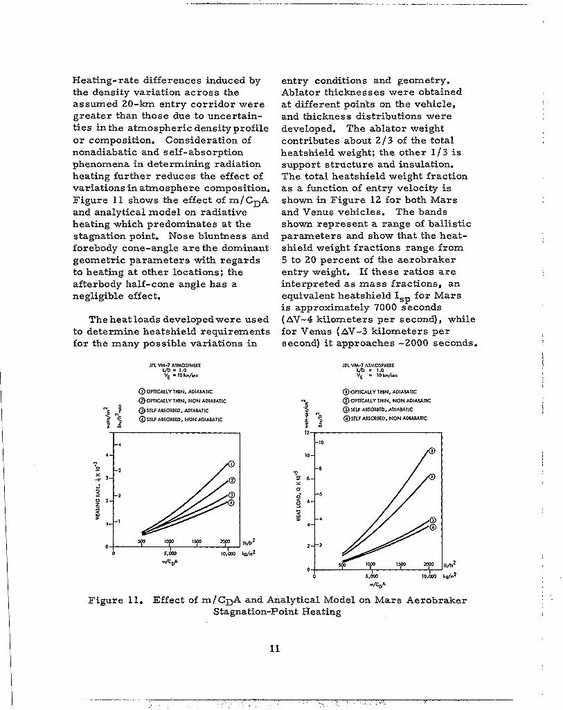
Heating-rate differences induced by the density variation across the assumed 20-km entry corr idor were greater than those due to uncertain- ties in the atmospheric densityprofile or composition. Consideration of nonadiabatic and self-absorption phenomena in determining radiation heating further reduces the effect of variations in atmosphere composition. Figure 11 shows the effect of m/CDA and analytical model on radiative heating which predominates at the stagnation point. Nose bluntness and forebody cone-angle are the dominant geometric parameters with regards to heating at other locations; the afterbody half-cone angle has a negligible effect.
The heat loads developedwere used to determine heatshield requirements for the many possible variations in
JPL VM-7 ATMOSPHERE vb 1.0 VE - lOkm/YC
@OPTICALLY THIN, ADIABATIC
@OPTICALLY THIN, NONADIABATIC
@SELF ABSORBED, ADIABATIC N5 J 2 ';. @SEI€ ABSORBED, NONADIABATIC I r r ,
- 4-
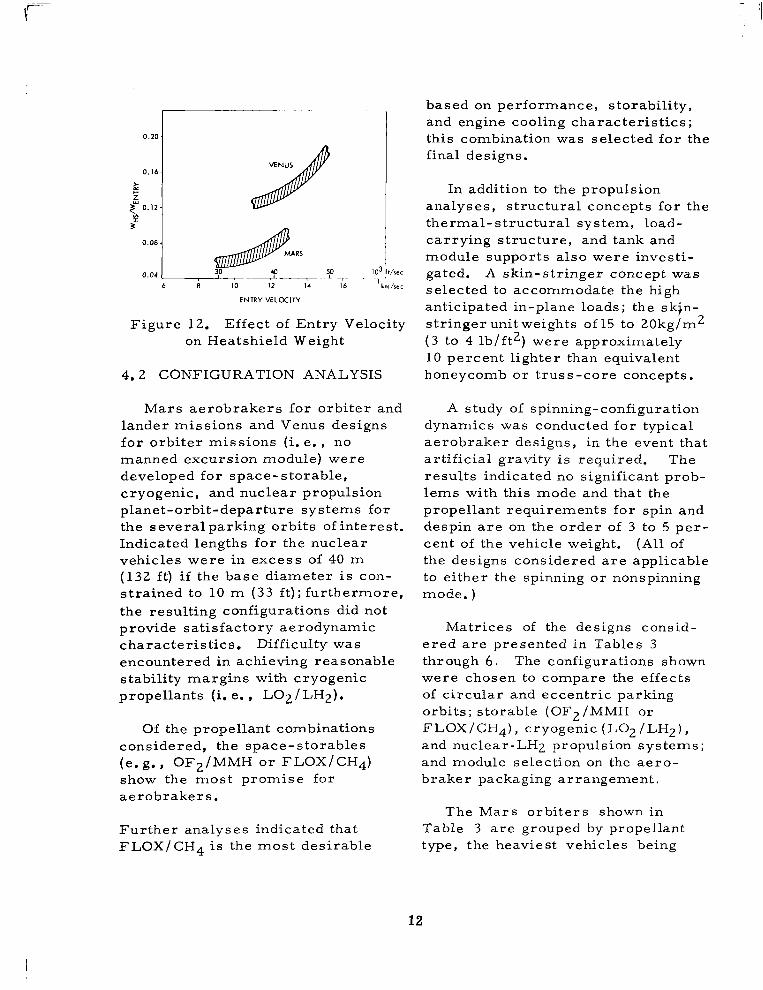
entry conditions and geometry. Ablator thicknesses were obtained at different points on the vehicle, and thickness distributions were developed. The ablator weight contributes about 2 / 3 of the total heatshield weight; the other 1/3 is support structure and insulation. The total heatshield weight fraction as a function of entry velocity is shown in Figure 12 for both Mars and Venus vehicles. The bands shown represent a range of ballistic parameters and show that the heat- shield weight fractions range from 5 to 20 percent of the aerobraker entry weight. If these ra t ios are interpreted as mass fractions, an equivalent heatshield Isp for Mars is approximately 7000 seconds (AV-4 kilometers per second), while for Venus (AV-3 kilometers per second) it approaches -2000 seconds.
JPLVM-7 ATMOSPHERE
: 1i0WYC
@OPTICALLY THIN, ADIABATIC
N @ OPITCALLY THIN, N O N ADIABATIC
d @SELF ABSORBED, ADIABATIC 3 3 @SELF ABSORBED. NONADIABATIC
I2 t a
10
Figure 11. Effect of m/CDA and Analytical Model on Mars Aerobraker Stagnation-Point Heating
11
I
I
0 .20
0.16
k z 5 0. I2 j?
0.08
0.04 1 i 10 12 14 I 6
ENTRY VELOCITY
Figure 12. Effect of Entry Velocity on Heatshield Weight
4 . 2 CONFIGURATION ANALYSIS
Mars aerobrakers for orbi ter and lander missions and Venus designs for orbiter missions (i. e., no manned excursion module) were developed for space-storable, cryogenic, and nuclear propulsion planet-orbit-departure systems for the several parking orbits of interest . Indicated lengths for the nuclear vehicles were in excess of 40 m (132 ft) i f the base diameter is con- strained to 10 m (33 ft); furthermore, the resulting configurations did not provide satisfactory aerodynamic characteristics. Difficulty was encountered in achieving reasonable stability margins with cryogenic propellants (i. e. , LO2 /LHz).
Of the propellant combinations considered, the space-storables (e. g., OF2/MMH or FLOX/CH4) show the most promise for aerobrakers .
Further analyses indicated that FLOX/CH4 is the most desirable
based on performance, storability, and engine cooling characteristics; this combination was selected for the final designs.
In addition to the propulsion analyses, structural concepts for the thermal-structural system, load- carrying structure, and tank and module supports also were investi- gated. A skin-stringer concept was selected to accommodate the high anticipated in-plane loads; the skin- stringer unit weights of 15 to 20kg/m2 (3 to 4 lb/ft2) were approximately 10 percent lighter than equivalent honeycomb or truss-core concepts.
A study of spinning-configuration dynamics was conducted for typical aerobraker designs, in the event that art if icial gravity is required. The results indicated no significant prob- lems with this mode and that the propellant requirements for spin and despin are on the order of 3 to 5 pe r - cent of the vehicle weight. (All of the designs considered are applicable to either the spinning or nonspinning mode. )
Matrices of the designs consid- ered are presented in Tables 3 through 6 . The configurations shown were chosen to compare the effects of circular and eccentric parking orbits; storable (OF2/MMH or FLOX/CHq), cryogenic (LO2 /LHz), and nuclear-LH2 propulsion systems; and module selection on the ae ro - braker packaging arrangement.
The Mars orbi ters shown in Table 3 a r e grouped by propellant type, the heaviest vehicles being
12

Table 3. M a r s Orbiter Mission Vehicles
MM: 8-man. 430 -day
Periapsis a l t i tude 300 km
Base diameter 10 m (33 ft)
Eccentricity
Propel lants
Length m f t
Entry weight lo3 kg lo3 lb
Injected weight lo3 kg lo3 l b
0
S
19.7 65
265 584
279 614
0.6
S
18.8 61
186 410
195 430
0 .9
S
18.8 61
165 364
173 382 -~
~ ~~
0 . 6
C
23 .4 77
188 41 3
197 434
0 . 9
C
21.5 71
161 353
168 370
~
0 . 6
N
29 .6 97
164 362
173 3 80
Table 4. Mars Lander Mission Vehicles " . ~ ~
ERM: Apollo
MEM: direct , Apollo
MM: 8-man, 430-day
Periapsis al t i tude 300 km
~~
Base diameter 10 m (33 ft), except as noted
" ~
Eccentricity
Propellants
Length m f t
1 26.6 87
Injected weight IO3 kg l o 3 lb 685
~~ ~~
~
" 9 . 6
S
26. 6 87
247 543
260 571
- 0 . 6
C
40.0 127
244 536
256 563
D =11.7 m I (39 ft) I 0 . 9
C
34.6 113
227 500
239 526
0 . 6
C
30.0 98.5
242 533
254 560
0 . 6
N
40.6 138
220 484
231 509
13
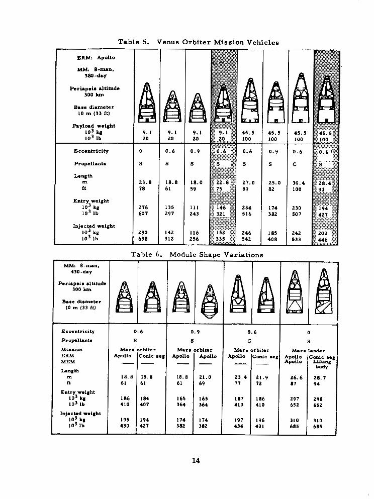
Table 5. Venus Orbiter Mission Vehicles
ERM: Apollo
MM: 8-Ip.n, 380-d8y
Periapri r a l t i tude 300 km
B8re di8me te r 10 rn (33 ft)
h y l o r d w e i g h t IO3 kg IO3 lb
Eccentricity
Propellantr
Longth
f t m
Entry weight IO3 kg lo3 l b
Injected weight IO3 kg lo3 lb
Poriapmir altitude 300 k m
B8re diameter 10 rn (33 ft)
Eccentricity
Propelhnt r
Mimmion ERM MEM Langth
m ft
Entry roiaht IO3 kg IO3 lb
Injoctod ro i ah t IO3 ka IO3 lb
"I-
23.8 1 18.8 78 61
276 60 7
290 638 -
Table 6 .
135 297
I42 312 -
0 . 6
s Mar. orbiter
Apollo (Conic reg
-I-
45.5 100
0.9
S
25.0 82
174 3 82
185 40 8
Module Shape Variations 1
M8rr Apollo -
18.8 61
165 364
174 382
0.9
S 'I rbiter Apollo - 21.0 69
165 364
174 382
I 0 .6
C
Mar. Apollo -
23.4 77
187 413
197 434
rbitor Zonic re - 21.9 72
I86 410
196 43 I
Apollo Apollo
26.6 87
297 652
310 685
zonic ..I
b-JY Ltfting
28.7 94
298 652
310 685
14

located to the left of the chart. It is readily apparent that, while' the cryogenic and nuclear propellant aerobrakers are l ighter for a given mission, they are also much longer. The three smallest orbiters use storable propellants for planet departure; all are approximately the same size, with length-to-diameter ratios of about two. This allows a fairly large aft-cone angle, resulting in a center of pressure located aft of the cone intersection. In order to achieve an acceptable center of gravity, the POE propellant is stored in the annulus around the three-floor mission module.
Based upon the investigations conducted during the study, a recom- mended Mars aerobraker orbiter, indicated by the shading in Table 3, was developed. This configuration is powered by a single stage for planet departure, using storable FLOX/CH4 propellants and an aero- spike engine. The mission module chosen has two floors, curved bulk- heads, and a diameter of 8.2 m (27 ft). It incorporates an equipment bay on the forward end in which antennas, telescopes, solar panels, and scientific instruments are stored, The aft end of the MM provides storage for life-support gases, outbound-course-correction propellant tanks, and a scientific laboratory area. The probe compartment is located at the aft end of the vehicle.
Aerobraker vehicles for the Mars landing missions are shown in Table 4. The configurations afford a comparison of the effects of park-
l I ing orbit on vehicle design for each I
of the propulsion systems considered: i. e., storable (OF2/MMH, FLOX/ CHq), cryogenic (L02/LH2), and nuclear (LH2). The comparison also is made between the several propul- sion systems for a given orbit (e. g., e = 0. 6). This group of landers is arranged similarly to the orbiter family, the heaviest vehicle shown to the left.
Mars vehicles using nuclear (LHz) propulsion are the lightest of the total Mars lander spectrum: their weights run about 10 percent less than the cryogenic landers and 11 percent less than the storable landers for a given orbit. The 10-m (33-ft) base diameter configuration sized for the 0.6 e orbit approaches a length-to-diameter ratio of about five, because the LH2 located for- ward of the MM requires such a large volume that only a small aft- cone angle is allowed. The MEM and probes preclude the propellant from being in the aft end, with its larger volume, because of their own size and position requirements. These lengths and packaging require- ments create difficult stability problems and preclude the use of nuclear (LH2) propulsion for aero- braker vehicles.
An integrated lander design, indicated by the shading in Table 4, was developed. This configuration achieves a proper balance between cg and cp and makes use of FLOX/ CH4 propellants in an aerospike engine. The FLOX/CH4 combination appears to present less long-term storage problems than the other storables considered (OFz/MMH).
15

For the Venus orbiter family shown in Table 5, aerobrakers carrying an Apollo-shaped ERM and either a l ight or a heavy probe com- plement were developed to compare the effects of parking orbits and pro- pulsion systems. All the spacecraft shown a r e similar in arrangement and carry the single planet-departure propulsion stage in the nose, followed by the ERM, MM, and probes. A recommended design, indicated by the shading in Table 5 was generated. For purposes of commonality, the exterior shape and basic arrange- ment are identical to the equivalent Mars aerobraker, even though the Venus mission requires smaller POE tanks. If the POE tanks were filled, an orbit with an eccentricity a s low as 0.2 could be achieved at Venus.
Table 6 i l lust rates a number of Mars aerobrakers (both orbiters and landers) configured to compare the effect of the conic segment ERM and the lifting body MEM. Also, two Mars orbiter designs, sized for highly eccentric orbit (i. e . , e = 0.9) and using storable propellants, were developed to compare the effect of an external probe compartment on the aerobraker length from base plane to nose.
Little or no difference was found in the length o r packaging arrange- ments between the Apollo-shaped and conic segment ERM, Storing all the probes externally aft of the bulkhead resulted in a 5-percent shorter Mars orbiter. The lifting body MEM requires about the same length com- partment as the Apollo-shaped MEM.
No appreciable change in spacecraft gross weight is noted for these shape variations.
Figure 12 presents a summary of the vehicle injected weight variation with parking orbit eccentricity for both Mars and Venus missions. Also shown a r e the weights for direct and staged Mars excursion modules.
4.3 RECOMMENDED CONFIGURATIONS
Recommended aerobraker designs include Mars and Venus orbiters and Mars lander, Venus orbiter vehicles sized for a planet departure AV of 3.6 km/sec (11,800 ft/sec), equiv- alent to an eccentricity of 0. 6 a t Mars and 0.2 at Venus. These designs used FLOX/CH4 for the departure propulsion and carry Apollo-shaped Earth-reentry modules. The Mars lander also carries an Apollo-shaped excursion module. Schematic profiles of the four recommended designs and pertinent weight data are shown shaded in Tables 3 through 6.
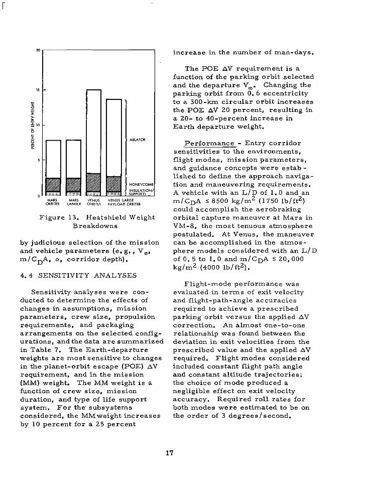
Heatshield weight breakdowns for the four selected configurations are shown in Figure 13. The weights ranged from 7 to 15 percent of the vehicle entry weight; the Venus orbiter required the highest heat- shield design was considered for both Mars and Venus entry (assuming the spacecraft could be trimmed at the proper angle of attack). The weight penalties imposed on the recommended designs for a common heatshield can approach 50 percent of the heatshield weight. This penalty can be reduced
16
r
ABLATOR
HONEYCOM
INSULATION SUPPORTS
ORBITER LANDER ORBITER PAYLOAD ORBITER MARS MARS VENUS VENUS LARGE
Figure 13. Heatshield Weight Breakdowns
by judicious selection of the mission and vehicle parameters (e. g., Ve, m/CDA, cy, corridor depth).
4.4 SENSITIVITY ANALYSES
Sensitivity analyses were con- ducted to determine the effects of changes in assumptions, mission parameters, crew size, propulsion requirements, and packaging arrangements on the selected config- urations, and the data are summarized in Table 7. The Earth-departure weights are most sensitive to changes in the planet-orbit escape (POE) AV requirement, and in the mission (MM) weight. The MM weight i s a function of crew size, mission duration, and type of life support system, For the’ subsystems considered, the “weight increases by 10 percent for a 25 percent
increase in the number of man-days.
The POE AV requirement is a function of the parking orbit selected and the departure V,. Changing the parking orbit from 0.6 eccentricity to a 300-krn circular orbit increases the POE AV 20 percent, resulting in a 20- to 40-percent increase in Earth departure weight.
Performance - Entry corridor sensitivities to the environments, flight modes, mission parameters, and guidance concepts were estab - lished to define the approach naviga- tion and maneuvering requirements. A vehicle with an L/D of 1.0 and an m/CDA 5 8500 kg/m2 (1750 lb/ft2) could accomplish the aerobraking orbital capture maneuver at Mars in VM-8, the most tenuous atmosphere postulated. At Venus, the maneuver can be accomplished in the atmos- phere models considered with an L/D of 0.5 to 1.0 and m / C D A 5 20 ,000 kg/m2 (4000 lb/ft2).
Flight-mode performance was evaluated in terms of exit velocity and flight-path-angle accuracies required to achieve a prescribed parking orbit versus the applied AV correction. An almost one-to-one relationship was found between the deviation in exit velocities from the prescribed value and the applied AV required. Flight modes considered included constant flight path angle and constant altitude trajectories; the choice of mode produced a negligible effect on exit velocity accuracy. Required roll rates for both modes were estimated to be on the order of 3 degrees/second.
17

Table 7. Aerobraker Spacecraft Weight Sensitivities
Module
Mission module
8 men - 430 days 8 men - 380 days
Earth reentry module
8 men - Apollo shape
Probes
9., oao ~g (20, ooo 1b) 3 6 , 3 2 0 R g (80, 000 lb)
Tars excursion module
4 men - 30 days Apollo shape
Propulsion Svstem
htbound course :orrection
htbound spin md despin
Jlanet orbit .ttainment and naintenance
'lanet orbit spin nd despin
'lanet orbit scape
.eturn spin and e spin
.eturn course 2rrection
c rnlsec
7 6 152
132 6 6
152 7 6
6 6
3 , 600
2 , 7 0 0
6 6
7 6
f t lsec
250 500
440 220
500 250
220
1, aoo
a, 200
220
250
t Change
A
110% n module veight
:207'0 AV I2070 av 12 cycles:: 11 cycle
120% av :20qo av
:1 cycle
110% AV
: l O q o AV
11 cycle
I2070 av
Percent Change in Injected Weight
I Mars
Lander
*4. 1
f l . 1
fO. 5
?rl. 9
-
+o. a f l . 0
*o. a
*o. 2
t 1 0 . 7 - 7. 6
*o. 3
!Lo. 3
l rb i te l
f5. 1
f l . 4
fO. 7
~. .
f o . a f l . 0
f o . a
*o. 2
-13. a 9 . a
*o. 4
*o. 4
Venus Orbiter
Large Payload
f 3 . 3
f l . 0
*o. 7 *2 .4
fO. 4
fO. 5
fO. 4
fO. 3
t 4 . 3 - 3 . 4
fO. 4
*o. 3
J
Small Pa
f4 . 1
*l. 3
+o. 9
~. - . .. - -
0 . 4 fO:
*o. 5
*o. 4
fO: 4
*5. a -4. 7
f0. 5
f0. 3
~~
yload
I
18
Heating and Heat Protection - compromises in the mission and vehicle par.ameters. Convective and radiative heating
rates for the selected vehicles were computed using methods represent- ative of the current state of the art. I t was found that the choice of analytical model used to obtain the radiative heating (i. e. , adiabatic, nonadiabatic with self-absorption, etc.) was more significant than the variations in the atmospheric compo- sition. At Mars, there was a decrease in maximum heating rate of 15 percent in going from VM-7 to the MSG-3 atmosphere. Changing the analytical model from the simple adiabatic case to the sophisticated nonadiabatic, self-absorption approach results in a stagnation heating rate almost 50 percent lower, while peak heating at the other locations is reduced by as much as a factor of five. A 20-percent increase in entry velocity increased the peak stagnation heating rate by a factor greater than two; increasing the angle of attack from 8 degrees to 28 degrees increasedthe radiative heating rate on the conical surface by more than an order of magnitude.
The effects of these uncertainties on the heat protection system weights were reflected in heatshield weight variations of almost 100 percent, or vehicle entry weight variations of from 7 to 15 percent. The heat- shield design for the Mars mission was 35 percent lighter than the Venus heatshield. If a common heatshield design were used for both missions, the weight-in-Earth-orbit penalty for the Mars mission would be 3 to 8 percent. This penalty can effec- tively be eliminated by suitable
Structure andshielding -Integrated structure unit weights of 15 to 20 kg/ m 2 ( 3 to 4 lb/ft2) were found for the range of configurations studied. These weights include the load- carrying s t ructure , as well as meteoroid protection requirements to assure a 99-percent probability of no penetration in 430 days, given the nominal meteoroid flux model. ( 9 ) The unit weights derived were more sensitive to the analytical method applied than to the mission assumptions.
Design Integration - Sensitivities of the configuration packaging arrangements to changes in the orbital parameters and candidate propulsion system for Mars lander vehicles were illustrated earlier in Table 3 through 6. The Earth reentry module (ERM) shape was found to have no effect on the vehicle length or arrangement . An Apollo-shaped Mars excursion module (MEM) was selected; use of the 16-m (35-ft) long lifting body MEM does not severely penalize the packaging arrangement. The effect of 4- to 12-man crews on the packaging arrangements is not clear because crew free-volume requirements are poorly defined. , For example, a mission module designed for 8 men with a free volume per man of 20 m 3 (700 ft3) could be,: used for 12 men a t 13 m3 (470 ft3)' '
free volume per man; recommended
(')Manned Planetary Flyby Missions Basid on Saturn/ Apollo Systems, op. cit.
19

free volumes range from 10 to 2 0 m 3 per man, (10)
4.5 MODULAR APPROACH TO VEHICLE SYNTHESIS
In the latter phases of the config- uration analysis, it became apparent that a se r ies of common modules could be used to synthesize the aerobraker. The approach, illustrated in Figure 14, is attractive because only four basic segments a r e needed for all the orbiting and landing missions of interest.
('"Davenport, E . W . , Congdon, S.P., and Pierce, 6. F. "The Minimum Volumetric Requirements of Man in Space, " AIAA Paper No. 63-250, presented at AIAA Summer Meeting i n Los Angeles, California (17-20 June 1963).
The vehicle is comprised of three major modules; i. e., a propulsion (or nose module), a mission module, and a probe or probe-and-lander module. Initially, the mission and probe modules for each configuration were developed as a unit to satisfy the cp-cg relationships, volumetric requirements, and the base-diameter constraints. After the configurations were analyzed, it appeared possible to treat these modules as discrete components in order to establish a mission module shape common to both the orbiter and lander configurations.
Each spacecraft heatshield initially was treated as a unique design; i f common elements were to be specified for the propulsion, mission, and probe modules, a common heatshield capable of satisfying multimission
Figure 14. Modular Approach to Aerobraker Synthesis
20

I
and spacecraft requirements might be expected to suffer some weight disadvantage. It was found that although the Mars heatshield weights increased 33 to 36 percent to achieve commonality, the gross spacecraft weight increase would be less than 3 percent; the Venus heatshield weight would increase 2 to 6 percent and the spacecraft gross weight would increase less than 1 percent. These increases could be reduced to negli- gible values by altering the mission- system parameters sl ightly (i. e., velocity and L/D). Although some penalty would be incurred in the injection stage, the obvious advantage of a common heatshield appears to make this a worthwhile trade-off.
4.6 TEST AND QUALIFICATION CONSIDERATIONS
Acceptance of the aerobraker mode will require sufficient testing to establish a high level of confi- dence in the aerobraking mission. The requirements for these tests were considered briefly. It was
found that the aerobraking maneuver is of the same order of complexity as return and entry along a maximum range trajectory on current Apollo lunar missions where the Apollo exits the atmosphere after being slowed to near orbital velocity and eventually enters again to achieve the desired range. This entry profile is, in almost all respects, a valid simulation of the aerobraking concept.
Additional aspects of the vehicle's design and performance could be tested in a combination of ground, earth-atmosphere, and cislunar space environments. No planetary- based tests would be required beyond the currently planned unmanned data-gathering probes. If the mod- ular approach to the aerobraker design is adopted, parts of the vehicle could be used as Earth- orbital space stations while being tested for the more demanding planetary missions. Although this approach is most promising, i t has not been studied in detail.
5.0 RELATIONSHIP TO OTHER NASA PROGRAMS
The current study was performed for the Mission Analysis Division of NASA's Office of Advanced Research and Technology and is the fifth in a re la ted ser ies of manned interplane- tary mission requirements studies conducted by North American Rock- well. The ser ies s ta r ted in 1964 with Contract NAS2-1408, "Manned Mars Landing and Return Mission Study. I '
The baseline aerobraker configura- tion used in the present investigation was developed in 1964 under Contract NAS9 - 1748, "Study of Subsys terns Required for a Manned Mars Mission Modulell; a sensitivity analysis of the baseline aerobraker vehicle was conducted in 1965 under Contract NAS2 - 247 7 , Study of Unmanned Systems to Evalute the Martian
21

Environment. The results of a con- current study of the Mars excursion module, conducted under Contract NASS - 6464. entitled "Definition of Experimental Tests for a Manned Mars Excursion Module, ( I were used directly in this study. Two other parallel studies which furnished val- uable data in some areas were Con- t rac t NAS8-18025, "Study of Manned Planetary Flyby Missions Based on Saturn/Apollo Systems, f I and Con- t rac t NAS2-3918, "Study of Techno- logical Requirements Common to Manned Planetary Missions.
More comprehensive data have been generated in this investigation of the aerobraking mode to effect planet-orbital capture. The size- and weight-scaling relationships developed can readilybe extrapolated to assess effects of mission date, duration, and flight mode. The designs developed illustrate possible packaging arrangements and volume utilization and will serve as the base- lines for the next series of manned planetary capture and landing studies.
6.0 SUGGESTIONS FOR F U T U R E WORK
Two broad areas of future studies are recommended as a resul t of the work accomplished. The first is described as "Planetary Capture Mission-System Analyses" and the second as "Atmosphere Braking Vehicle Technology Studies.
6 .1 PLANETARY-CAPTURE MISSION-SYSTEM ANALYSES
The current study provides data which indicates that the aerobraking mode has a potentially significant advantage over the retrobraking mode when the two are compared on the basis of weight in Earth orbit. Furthermore, the technology devel- opment requirements in propulsion (i. e . , nuc lea r sys t ems) a r e more demanding for retrobraking than for aerobraking, inasmuch as the latter can be accomplished with a chemical planet-0rbit;departure stage. Aero-
braking appears feasible in the cur- rently postulated family of Mars .and Venus atmospheric models; a seg- mented modular vehicle concept which affords multiplanet, multimis- sion capability and has obvious eco- nomic attractions has been defined. Consequently, detailed comparative analyses of aerobraking and retro- braking should now be performed for a wide range of mission opportuni- ties. The analyses should consider developmental problems, cost, reliability, and schedule risk, as well as the system requirements.
The availability of an acceptable test and qualification plan for an aerobraker spacecraf t system, pref- erably one which could be conducted in the near-Earth environment, would go far in promoting acceptance of this mode. This program should encompass both scaled models and
22

the modularized segments to man rate the total system; detailed sizing, scaling, and simulation would be a prerequisite analysis. The modular approach to vehicle synthesis sug-
- gested by this investigation should be extended to both Earth-orbital and planetary-flyby missions, and the associated compromises (and penal- ties) in the mission and spacecraft requirements and capabilities should be identified.
6 .2 ATMOSPHERE-BRAKING- VEHICLE TECHNOLOGY STUDIES
characterist ics of the modular spacecraft. Evaluate candidate tri- conic configurations to assure ade- quate stability and lift capability. Study entry dynamics in sufficient de tail to derive the guidance and con- trol system requirements, including the reaction control system. Parking orbit characterist ics for selected mission opportunities must be examined in more detail s o that orbit precession is taken into account as well as the proper orientation of the approach and departure V, vectors.
Heating and Heat Protection - Refine the computation of the radia-
Suggested technology studies of tive heating environment to include the atmosphere-braking vehicle are the contribution of atomic lines presented briefly in these concluding considering a self -absorbed, nonadi- paragraphs. abatic flow field. The effects of
ablation-product radiation in the flow Crew Systems and Functions -
Establish crew timelines, functional operations, and associated crew system requirements (e. g . , f ree volume per man, displays and con- trols, living quarter arrangements, etc. ). These data are needed for the design and planning of ground and Earth-orbital tests.
Vehicle Design - Determine the design requirements for the modular approach to spacecraft synthesis, including the arrangements of the major modules (i.e., ERM, MEM, probes) within the spacecraft, heat- shield joints, separation planes, external appendages (such as radia- tors and antennas), and manufactur- ing considerations.
Aer odynamic s and Entry Performance - Establish the aero- dynamic coefficients and stability
field and wake should be examined in de tail. Investigate the properties of high-density carbon-based ablative materials in the regions of high heat f l u x . Experimental verification of ablation rates and material reactions in chemical models of the candidate atmospheres must be obtained. The heatshield design currently is envi- sioned to be composed of a large number of panels which must cover a surface area of approximately 750 m2 (8000 ft2). m-e-se panels are jet t i- soned after -exit from the'atmosphere. Determine the performance of such a segmented heatshield design and investigate other candidate heatshield concepts. Determine entry-velocity and angle -of-attack requirements for a common heatshield for both planets.
CR-1131 NASA-Langley, 1968 - 30 23