nasa c i7l3o-s united states patent patent no.: … · 2013-04-10 · u.s. patent documents...
TRANSCRIPT

Source of Acquisition NASA Washington, D. C
I7L3o-S (12) United States Patent (io) Patent No.: us $,960,88S'Bl
Foster (45) Date of Patent: Nov. 1,2005
METHOD OF PRODUCING AND ACCELERATING AN ION BEAM
Inventor: John E. Foster, Strongsville, OH (US)
Assignee: The United States of America as represented by the Administrator of the National Aeronautics and Space Administration, Washington, DC (US)
Subject to any disclaimer, the term of this patent is extended or adjusted under 35 U.S.C. 154(b) by 112 days.
Notice:
Appl. No.: 10/753,183
Filed Jan. 5,2004
Related U.S. Application Data Division of application No. 10/215,129, filed on Aug. 8, 2002, now Pat. No. 6,696,792.
Int. Cl? ................................................. HOlJ 7/24 U.S. Cl. ............................ 315/111.81; 315/111.41;
3 15/11 1.61 ; 3 131359.1 ; 3 13/362.1; 601202; 60/203.1
Field of Search ........................... 315/501, 111.21,
313/359.1,362.1; 2501423 R, 423 F; 118/723 FI, 1181723 HC; 60/202,203.1
3 15/111.41-111.91; 219/121.36, 121.55;
References Cited
U.S. PATENT DOCUMENTS
4.596.945 A * 6/1986 Schumacher et al. ....... 3151344 4,937,456 A 6/1990 Grim et al. ................. 250/427 5,359,258 A 10/1994 Arkhipov et al. ........ 313/359.1 5,475,354 A 12/1995 Valentian et al. ........... 3351296
5,509,266 A 4/1996 Morosov et al. ........... 60/203.1 5,523,652 A * 6/1996 Sferlazzo et al 5,581,155 A IN996 Morosov et al. ........ 315/111.21 5,751,113 A 511998 Yashov et al. .......... 315/111.21 5,847,493 A 12/1998 Yashov et al. ......... 313/231.31 5,892,329 A 4/1999 Arkhipov et al. ....... 315/111.91 6,031,334 A 2/2000 Meyer ................... 315/111.01 6,075,321 A 6/2000 Hruby ................... 315/111.91 6,150,764 A 11/2000 Hruby et al. ........... 315/111.61 6,200,911 B1 * 3/2001 Narwankar et al. ......... 438/758 6,208,080 B1 3/2001 King et al. ............. 315/111.41 6,215,124 B1 4/2001 King ...................... 250/423 R 6,279,314 B1 8/2001 Valentian et al. ............. 60/202 6,611,106 B2 * 8/2003 Monkhorst et al. ..... 315/111.41
2004/0104682 A1 * 6/2004 Horsky et al. .......... 315/111.81
* cited by examiner
Primary Examiner-Haissa Philogene (74) Attorney, Agent, or Firm-Kent N. Stone
(57) ABSTRACT
A method of producing and accelerating an ion beam comprising the steps of providing a magnetic field with a cusp that opens in an outward direction along a centerline that passes through a vertex of the cusp: providing an ionizing gas that sprays outward through at least one cap- illary-like orifice in a plenum that is positioned such that the orifice is on the centerline in the cusp, outward of the vortex of the cusp; providing a cathode electron source, and posi- tioning it outward of the orifice and off of the centerline; and positively charging the plenum relative to the cathode elec- tron source such that the plenum functions as m anode. A hot filament may be used as the cathode electron source, and permanent magnets may be used to provide the magnetic field.
3 Claims, 4 Drawing Sheets
https://ntrs.nasa.gov/search.jsp?R=20060009300 2018-07-09T02:28:06+00:00Z

U.S. Patent Nov. 1,2005 Sheet 1 of 4 US 6,960,888 B l
FIGURE 1 I sza-,
1
t
\ 52b
FIGURE 2

U S . Patent Nov. 1,2005 Sheet 2 of 4 US 6,960,888 B1
FIGURE 3 c56

U.S. Patent Nov. 1,2005 Sheet 3 of 4 US 6,960,888 B l
POSITION, mm FIGURE 5
0.6
0.5
0.4
> 0.3 a >-
7 Os* 0.1
0
0.60 SCCM . ... .. 0.75 SCCM
-0.1
ION RETARDING POTENTIAL (ION ENERGY), eV
FIGURE 6

U.S. Patent Nov. 1,2005 Sheet 4 of 4 US 6,960,888 B1
DISCHARGE VOLTAGE, V
FIGURE 7
I I I I I f 0.55 0.7 0.85 I 1.15 1.3 150 I
0.4 FLOW, SCCM
FIGURE 8

US 6,960,888 B1 1
METHOD OF PRODUCING AND ACCELERATING AN ION BEAM
This is a divisional of application Ser. No. 10/215,129, which was filed on Aug. 8, 2002 now U.S. Pat. No. 6,696, 792.
ORIGIN OF THE INVENTION
The invention described herein was made by an employee of the United States Government and may be manufactured and used by or for the Government for Government pur- poses without the payment of any royalties thereon or therefor.
TECHNICAL FIELD OF THE INVENTION
The present invention relates to a plasma generator and accelerator and, more particularly to a low power, compact plasma accelerator that can be used for satellite propulsion, drag reduction and station-keeping, or for ion plasma mate- rial processing in a vacuum.
BACKGROUND OF THE INVENTION
There is a need for a simple, low power, light-weight, compact, high specific impulse electric propulsion device to satisfy mission requirements for micro and nano-satellite class missions. Satisfying these requirements entails addressing the general problem of generating a sufficiently dense plasma within a relatively small volume and then accelerating it in a way that generates a net thrust reaction force in a desired linear direction. Known means for ion generation and propulsion generally require relatively large containment volumes in order to achieve reasonable ioniza- tion efficiencies, therefore new means are needed in order to achieve effective scaled-down propulsion devices.
Recent prior art electric propulsion devices and plasma accelerators are commonly some form of Hall effect thrust- ers (Hall accelerators or Hall engines). A conventional Hall effect thruster generally comprises an accelerating channel arranged along an axis with an anode and a propellant source at a first, generally closed, end of the channel, and a cathode (electron source) at a second, generally open, end of the channel. The cathode and anode establish an electric field with a gradient generally aligned with the axis of the channel. A system of magnets is arranged so that a magnetic field crosses the channel.
To continue the description of the Hall effect thruster, an exemplary thruster is presented comprising an annular accel- erating channel extending circumferentially around the axis of the thruster and also extending in an axial direction from a closed end to an open end. The anode is usually located at the closed end of the channel, and the cathode is positioned outside the channel close to its open end. Means is provided for introducing a propellant, for example xenon gas, into the channel and this is often done through passages formed in the anode itself or close to the anode. A magnetic system applies a magnetic field in the radial direction across the channel and this causes electrons emitted from the cathode to move circumferentially around the channel. Some but not all of the electrons emitted from the cathode pass into the channel and are attracted down the electric field gradient towards the anode. The radial magnetic field deflects the electrons in a circumferential direction so that they move in a spiral trajectory, accumulating energy as they gradually drift towards the anode. In a region close to the anode the
2 electrons, collide with atoms of the propellant, causing ionization. The resulting positively charged ions are accel- erated by the electric field towards the open end of the channel, from which they are expelled at great velocity,
5 thereby producing the desired thrust. Because the ions have a much greater mass than the electrons, they are not so readily influenced by the magnetic field and their direction of acceleration is therefore primarily axial rather than cir- cumferential with respect to the channel. The ion stream is
IO at least partially neutralized by those electrons from the cathode that do not pass into the channel.
Conventionally, the required radial magnetic field has been applied across the channel using an electromagnet having a yoke of magnetic material which defines poles on
IS opposite sides of the channel, Le. one radially inwardly with respect to the channel and the other radially outwardly with respect to the channel. An example is shown in European patent specification 0 463 408 which shows a magnetic yoke having a single cylindrical portion passing through the
20 middle of the annular channel and carrying a single mag- netizing coil; and a number of outer cylindrical members spaced around the outside of the accelerating channel and carrying their own outer coils. The inner and outer cylin- drical members are bolted to a magnetic back plate so as to
A recent example of the Hall effect thruster is disclosed in U.S. Pat. No. 5,847,493 (Yashnov, et al.; 1998) entitled “Hall Effect Plasma Accelerator”. The described invention in the US. Pat. No. 5,847,493 comprises the use of magnets
30 (permanent or preferably electric) wherein the magnetic poles are defined on bodies of material which are magneti- cally separate in order to allow greater freedom in selecting the dimensions of the thruster, particularly the length in the axial direction relative to the diameter of the accelerating
U.S. Pat. No. 5,751,113 (Yashnov, et al.; 1998), discloses a closed electron drift Hall effect plasma accelerator with all magnetic sources located to the rear of the anode. It is stated that this makes it possible to provide a Hall effect accelerator
40 with an optimum distribution of magnetic field inside the acceleration channel by means of a simpler and less heavy arrangement using a single source of magnetic field, such as a single coil or permanent magnet. As in all Hall effect thrusters, the magnetic field lines (13, as seen in FIG. 2)
45 extend laterally across the accelerating channel (1) over the anode (2) and propellant gas source (3) located at the closed end of the channel (see FIG. 1).
A problem common to the Hall effect thrusters is one of scaling its size. In general, it is difficult to scale down Hall
50 effect thrusters appreciably because of the magnetic field requirements. In smaller engines, the large transverse mag- netic fields required can hamper ion flow, thereby reducing the ion beam current. This is particularly problematic for such engines generating milliamp magnitude beams for
55 micro-thruster applications, wherein small thrust to power ratios make Hall effect thrusters impractical for micro- satellite applications. Another scaling problem is that elec- tromagnets do not scale well with size reduction because of heating issues and coil size required to achieve the desired
Hall effect thrusters generally employ hollow cathodes, and preferably employ electromagnets, thereby requiring fairly complicated, and thus heavier, control systems in order to control electromagnet current, gas flow in both the
65 anode and the discharge electrode, and cathode discharge current. Adding to the problems of complexity and weight, the hollow cathode consumes propellant.
25 form a single magnetic yoke.
35 channel.
60 field.

US 6,960,888 B1 3 4
U.S. Pat. No. 6,075,321 (Hruby; 2000), discloses a Hall quency oscillating electric field that interacts with magnetic field plasma accelerator with an inner and outer anode, fields to produce electrons and ions in a plasma. An annular- designed to deal with problems of wall heating and sputter- rectangular (“fistulous”) discharge electrode (14) is in close ing that are characteristic problems with Hall effect thrust- proximity to concentric annular-rectangular permanent mag- ers. 5 nets (15,16) that are arranged axially on either side of the
A non-Hall effect thruster is described by U.S. Pat. No. discharge electrode to generate magnetic field lines that loop 4,937,456 (Grim, et al.; 1990), that discloses a dielectric over the discharge electrode to cusps that are on either axial coated ion thruster comprising a cathode chamber (12) from side of the electrode. Rectangular parallel plate electrodes which free electrons flow into an attached ionization cham- (17, 18) at the top and bottom of the chamber are either ber (14) along with a flow of ionizable gas atoms. According io grounded or connected to a second high frequency source. to the abstract and to column 6 of the detailed description, The top electrode 17 is used, for example, as gas diffusion the free electrons are accelerated by a positive potential plate for diffusing a discharge gas or a process gas, wherein applied to the interior surface of the ionization chamber, the top electrode (17) is a perforated gas shower plate (37). causing the electrons to collide with atoms of the gas with It is an object of the present invention to provide a sufficient kinetic energy to create ions. The positively 15 compact plasma accelerator that overcomes problems such charged ions are accelerated toward a negatively charged as those described hereinabove for known devices, thereby perforated grid plate (24, 112), pass through the grid plate, providing sufficient thrust density to provide a simple, low and exit in a focused beam, providing thrust in the opposite power, light-weight, compact, high specific impulse electric direction. A plurality of bar magnets (20, 22, 108, 110) are propulsion device to satisfy mission requirements for micro arranged in a spaced apart circular array around the cathode 20 and nano-satellite class missions. chamber with a pole face of each of the magnets tangentially aligned with wall sections (16, 18,102,104) of the ioniza- tion chamber. The bar magnets define an axial geodesic picket fence arrangement that extends circularly about the According to the invention, a compact plasma accelerator cathode chamber, wherein the pole faces of adjacent bar 25 has components including a cathode electron source, an magnets that are in contact with the ionization chamber anode, a source of ionized gas, and a magnetic field source, alternate north and south polarity, so that a magnetic field wherein: the components are held by an electrically insu- extends between the opposite pole faces of adjacent bar lating body having a central axis, a top axial end, and a magnets. Although magnetic field lines are not illustrated, it bottom axial end The magnetic field source comprises: a can be seen from FIGS. 1 and 5, for example, that the 30 cylindrical magnet having an axis of rotation that is the same magnetic field lines will arch from pole to pole to create a as the axis of rotation of the insulating body, and magnetized scalloped line around the circumference of the ionization with opposite poles at its two axial ends; and an annular chamber with cusps occurring at each pole. As stated in magnet coaxially surrounding the cylindrical magnet, mag- column 7 of the detailed description, as a negatively charged netized with opposite poles at its two axial ends such that a electron is accelerated toward the wall sections, the mag- 35 top axial end has a magnetic polarity that is opposite to the netic field interacts with the moving charge, causing the magnetic polarity of a top axial end of the cylindrical electron to experience a force directed generally at a right magnet. The source of ionized gas is a tubular plenum that angle to its forward velocity. In response to this force, the has been curved into a substantially annular shape, posi- electrons are caused to spiral in a helical path, thereby tioned above the top axial end of the annular magnet such extending the mean path of the electrons to increase the 40 that the plenum is centered in a ring-shapedmsp of a probability that the electrons may strike an atom and ionize magnetic field generated by the magnetic field source, and it. Since the magnetic field lines that confine the plasma having one or more capillary-like orifices spaced around the within the ionization chamber bend laterally away from the top of the plenum such that an ionizing gas supplied through magnet poles (forming cusps), the surfaces of the poles are the plenum is sprayed through the one or more orifices. The not well protected by the magnetic field and would normally 45 plenum is electrically conductive and is positively charged be exposed to erosion due to impacts by high-energy elec- relative to the cathode electron source such that the plenum trons or ions, therefore dielectric coating (42) is provided to functions as the anode; and the cathode electron source is protect them from sputtering. Likewise, the outer surface of positioned above and radially outward relative to the ple- an emitter tube (28, 61, 128), and the inner and outer num. surfaces of the grid plate, are coated with a dielectric 50 According to the invention, the compact plasma accel- material to protect them from sputtering erosion. erator is further characterized in that the cylindrical magnet
Problems inherent in conventional ion thrusters with grids and the annular magnet are preferably permanent magnets. (e.g., U.S. Pat. No. 4,937,456) include significant erosion According to the invention, the compact plasma accel- issues for which dielectric coatings are needed to help erator is further characterized in that the plenum is prefer- provide protection, thereby adding weight and complexity. 55 ably enclosed in an electrically insulating material having an Furthermore, the use of grids along with charged chamber axially-oriented hole above each of the one or more orifices. walls require the use of multiple power supplies, thereby Furthermore, the body preferably has a cavity opening complicating the power processor unit. Finally, gridded upward and sized to enclose the plenum in combination with systems have inherently lower thrust density capability an electrically insulating cover plate that covers the cavity relative to gridless concepts. 60 and the plenum, and the cover plate has the axially-oriented
It is known that plasma accelerators can be used for holes. material processing in a vacuum by means of plasma ion According to the invention, the compact plasma accel- interaction with materials. U.S. Pat. No. 6,380,684 (Li, et al.; erator is preferably further characterized in that a field 2002) discloses a plasma generating apparatus and semicon- shaping plug is mounted in the insulating body above the ductor manufacturing method which generates a high-den- 65 cylindrical magnet such that the field shaping plug’s axis of sity plasma in a rectangular chamber using magnetron, high rotation is the same as the axis of rotation of the Cylindrical frequency discharge plasma generation, Le., a high fre- magnet, the field shaping plug is a cylinder that comes to a
BRIEF SUMMARY OF THE INVENTION
US 6,960,888 B1 5 6
conical point at its top axial end, and is made of a ferro- magnetic material; such that the field shaping plug concen- trates the magnetic field emerging from the top axial end of the cylindrical magnet to form a very narrow pointed cusp above the field shaping plug. Furthermore, the field shaping 5 plug is preferably made of mild steel.
According to the invention, the compact plasma accel- Reference will be made in detail to preferred embodi- erator is preferably further characterized in that the bottom ments of the invention, examples of which are illustrated in axial end of the insulating body is covered by a backing plate the accompanying drawing figures. The figures are intended made of a ferromagnetic material such that the backing plate 10 to be illustrative, not limiting. Although the invention is concentrates the magnetic field at the bottom axial end of the generally described in the context of these preferred embodi- cylindrical magnet and the annular magnet. Furthermore, the ments, it should be understood that it is not intended to limit backing plate is preferably made of mild steel. the spirit and scope of the invention to these particular
According to the invention, the compact plasma accel- embodiments. erator is further characterized in that the cathode electron 15 Certain elements in selected ones of the drawings may be source is preferably a hot filament, a field emitter type illustrated not-to-scale, for illustrative clarity. The cross- cathode or a very low flow rate hollow cathode type device. sectional views, if any, presented herein may be in the form Furthermore, the hot filament cathode electron source pref- of “slices”, or “near-sighted” cross-sectional views, omitting erably comprises one or more wires shaped in a ring that certain background lines which would otherwise be visible circumnavigates the plenum above and radially outward 20 in a true cross-sectional view, for illustrative clarity. relative to the plenum. Also, preferably a single power Elements of the figures can be numbered such that similar source powers the hot filament cathode electron source and (including identical) elements may be referred to with also the positively charged, anodic, plenum. It is within the similar numbers in a single drawing. For example, each of terms of the invention to use a separate power source to a plurality of elements collectively referred to as 199 may be power the filament supply. 25 referred to individually as 199a, 199b, 199c, etc. Or, related
According to the invention, the compact plasma accel- but modified elements may have the same number but are erator is further characterized in that the cathode electron distinguished by primes. For example, 109, 109, and 109” source may be one or more hollow cathodes. are three different elements which are similar or related in
According to the invention, the compact plasma accel- some way, but have significant modifications, e.g., a tire 109 erator is further characterized in that the electrically insu- 30 having a static imbalance versus a different tire 109’ of the lating body is preferably made using a ceramic material. same design, but having a couple imbalance. Such relation- Furthermore, the ceramic material is preferably a machin- ships, if any, between similar elements in the same or able ceramic. different figures will become apparent throughout the speci-
According to the invention, a method of producing and fication, including, if applicable, in the claims and abstract. accelerating an ion beam comprises the steps of: The structure, operation, and advantages of the present
a) providing a magnetic field with a cusp that opens in an preferred embodiment of the invention will become further outward direction along a centerline that passes through apparent upon consideration of the following description a vertex of the cusp; taken in conjunction with the accompanying drawings,
Other objects, features and advantages of the invention will become apparent in light of the following description thereof.
BRIEF DESCRIPTION OF THE DRAWINGS
35
b) providing an ionizing gas that sprays outward through at least one capillary-like orifice in a plenum that is positioned such that the orifice is on the centerline in the cusp, outward of the vertex of the cusp;
c) providing a cathode electron source, and positioning it outward of the orifice and off of the centerline; and
d) positively charging the plenum relative to the cathode electron source such that the plenum functions as an anode.
According to the invention, the method of producing and accelerating an ion beam preferably further comprises the steps of:
e) using a hot filament for the cathode electron source; and f) powering both the hot filament cathode electron source
and the positively charged, anodic, plenum with a one or more power sources.
According to the invention, the method of producing and accelerating an ion beam preferably further comprises the steps of:
g) using a hot filament for the cathode electron source; and
h) powering both the hot filament cathode electron source and the positively charged, anodic, plenum with one or more power sources.
According to the invention, the method of producing and accelerating an ion beam preferably further comprises the step of using permanent magnets for providing the magnetic field.
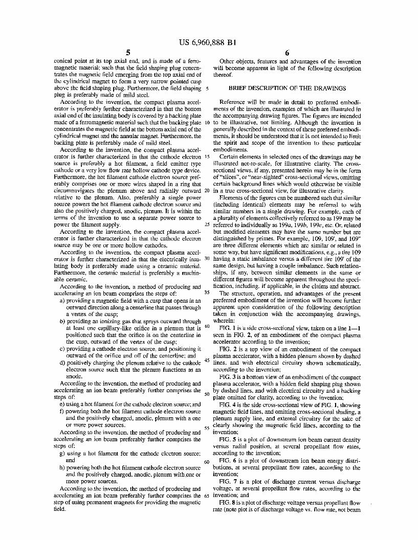
wherein: FIG. 1 is a side cross-sectional view, taken on a line 1-1
seen in FIG. 2, of an embodiment of the compact plasma accelerator according to the invention;
FIG. 2 is a top view of an embodiment of the compact plasma accelerator, with a hidden plenum shown by dashed
45 lines, and with electrical circuitry shown schematically, according to the invention;
FIG. 3 is a bottom view of an embodiment of the compact plasma accelerator, with a hidden field shaping plug shown by dashed lines, and with electrical circuitry and a backing plate omitted for clarity, according to the invention;
FIG. 4 is the side cross-sectional view of FIG. 1, showing magnetic field lines, and omitting cross-sectional shading, a plenum supply line, and external circuitry for the sake of
55 clearly showing the magnetic field lines, according to the invention;
FIG. 5 is a plot of downstream ion beam current density versus radial position, at several propellant flow rates, according to the invention;
FIG. 6 is a plot of downstream ion beam energy distri- butions, at several propellant flow rates, according to the invention;
FIG. 7 is a plot of discharge current versus discharge voltage, at several propellant flow rates, according to the
FIG. 8 is a plot of discharge voltage versus propellant flow rate (note plot is of discharge voltage vs. flow rate, not beam
40
50
60
65 invention; and
US 6,960,888 B1 7 8
current) when the discharge current is held constant at 98 milliamps, according to the invention.
A minimum number of screws 16 are utilized, for example four screws 16 spaced evenly around the perimeter of the cover plate 14 may be adequate to secure the cover plate 14 on top of the body 12. The screws 16 are made of a
INVENTION 5 nonmagnetic material (e.g., stainless steel), and threaded holes 32 can be provided in the body 12 by known means.
The present invention is directed toward satisfying a need The bottom of the body 12 has a matching circular backing for a low power, light-weight (compact), high specific plate 18 made of a ferromagnetic material (e.g., mild steel) impulse electric propulsion device to satisfy mission held in place by screws 26 that are recessed into the backing requirements for micro and nano-satellite class missions. io plate 18 enough to be at least flush with the bottom surface Satisfying these requirements entails addressing the general of the backing plate 18. A minimum number of screws 26 are problem of generating a sufficiently dense plasma within a utilized, for example four screws 26 spaced evenly around relatively small volume and then accelerating it. Such a the perimeter of the backing plate 18 may be adequate to plasma source utilizing a magnetic cusp to generate a dense secure the backing plate 18 onto the body 12. The screws 26 plasma is over small length scales has been built and tested. 15 are made of a nonmagnetic material (e.g., stainless steel), This approach could potentially mitigate the need for large and threaded holes 28 can be provided in the body 12 by containment volumes (size) in order to achieve reasonable known means. ionization efficiencies. The discharge plasma is both gener- The body 12 has an annular stepped-down portion 30 ated and accelerated via this approach using in principle surrounding the periphery of the top of the body 12. only a single power supply. Data suggests that the invention 20 Mounted on the stepped-down portion 30 are at least two should be capable of generating between 0.5 and 1.0 mN standoffs 21 for holding cathodes 48a,48b (collectively (milli-Newton) of thrust. Applications envisioned include referred to as 48), the standoffs 21 comprising bolts 20, low energy plasma processing in addition to propulsion for made of a nonmagnetic material, passing through insulating satellite station-keeping, drag reduction and primary propul- (e.g., ceramic) standoff sleeves 22, and screwed into sion for micro-satellites. The invention will be described in 25 threaded holes 24 provided in the stepped-down portion 30 the form of its preferred embodiment as a compact plasma of the body 12. In the preferred embodiment, the cathode 48 accelerator. is a hot filament cathode (e.g., double-braided tantalum wire
In its preferred embodiment, the invention employs a coated with barium carbonate, R-500 compound) that is magnetic cusp to effectively utilize discharge electrons for supported by the standoffs 21 and circumnavigates the cover ionization purposes and at the same time to generate suffi- 30 plate 14 in two portions 480,486 that are collectively ciently high sheath potentials for accelerating ions outward referred to as cathode 48. The circumnavigating cathode 48 to develop thrust. This approach utilizes a single electron is positioned above and radially outward relative to holes 46 source that provides not only discharge electrons but also that are spaced around the cover plate 14, and more fully electrons to neutralize the ion beam exiting the device. described hereinbelow. As illustrated in FIG. 2 for the Because this approach is gridless, it can develop higher 35 preferred embodiment, the inner diameter of the circum- thrust densities than a gridded ion source of similar dimen- navigating cathode 48 is located along the edge of the circle sions. Additionally, because the device operates on inert defined by the radially outermost edges of the holes 46. gases, the plume is non-contaminating to space craft sur- Current for the hot filament cathode 48 is provided by a faces. This point is to be contrasted with other options such power supply 54 that, for example, passes current through as PPT (pulsed plasma thruster) and FEEP (field enhanced 40 supply wire 520, through cathode wires 48a,48b, and back electric propulsion) systems which generate contaminating to the power supply 54 through supply wire 52b. The supply and often toxic plumes. wires 52u,52b are covered with insulating sleeves 50 (e.g.,
A preferred embodiment of the inventive accelerator is woven fiberglass sleeves). A discharge power supply 57 illustrated in several views in FIGS. 1-3, FIG. 1 being a provides power to a plenum supply line 43 through a supply cross-sectional side view with the cross-section taken along 45 wire 52c. The current for the discharge plenum supply line the line 1-1 as indicated in the top view of FIG. 2. FIG. 3 passes from the discharge power supply 57 through supply is a bottom view wherein a bottom plate has been removed wire 52c, and charges the plenum anode positively. Then, the to allow a view of internal elements. For convenience in this electrons leave the negative end of the discharge power description, the terms “top” and “bottom” will be used to supply 57 and enter the vacuum. The electrons collect at the indicate directions as they are illustrated in the side view of 50 anode and return to the discharge power supply 57 through FIG. 1. Of course these directions are not intended to be wire 52c. The supply wires 520,526, 52c, 52d are covered limiting, but rather are used to indicate relative positioning with insulating sleeves 50 (e.g., woven fiberglass sleeves). of various components. As is known in the relevant arts, Alternatively, other electron sources could be utilized for the plasma accelerators will function in any orientation relative cathodes 48 such as, for example, one or more hollow to a gravitational field. 55 cathodes or field emission type cathodes, however hot
With reference to FIGS. 1-3, the preferred embodiment of filament cathodes 48 are preferred because, among other the invention is a compact plasma accelerator (thruster) 10 reasons, they function with a single simple power supply, having major components that include a cathode electron and do not require a gas supply and are less sensitive to source, an anode, an ionizing gas source (also referred to as poisoning issues. a source of ionized gas), and a magnetic field source. The 60 The magnetic field source comprises two magnets, pref- components are held by a disc-shaped electrically insulating erably permanent to avoid the complication of added power body 12, preferably made of ceramic, e.g., a machinable supplies needed to power electromagnets. A cylindrical ceramic such as MacorTM. The top of the body 12 has a magnet 34 is mounted in a matching recess 35 of the body matching circular cover plate 14, also electrically insulating 12 such that the axis of rotation AR of the cylindrical magnet and preferably made of ceramic, e.g., MacorTM, held in place 65 34 is the same as the axis of rotation AR of the insulating by screws 16 that are recessed into the cover plate 14 enough body 12. The cylindrical magnet 34 is magnetized with to be at least flush with the top surface of the cover plate 14. opposite poles at its two axial ends. An annular magnet 36
DETAILED DESCRIPTION OF THE

US 6,960,888 B1 9 10
coaxially surrounds the cylindrical magnet 34, and is mag- nonmagnetic (e.g., stainless steel), and is positively charged netized with opposite poles at its two axial ends such that a to function as an anode. It can be seen t h a it is possible to top axial end has a magnetic polarity that is opposite to the use the single power supply 54 to positively charge the magnetic polarity of a top axial end of the cylindrical magnet plenum 42 (e.g., by means of a connecting wire 52c) in 34. For example, as shown in FIG. 4, the top axial end of the 5 addition to powering the hot filament cathode 48. The cylindrical magnet 34 is a “north” (N) pole and the bottom negatively charged hot filament cathode 48 electron source axial end of the cylindrical magnet 34 is a “south” (S) pole; is positioned above and radially outward relative to the whereas the top axial end of the annular magnet 36 is a plenum 42 and relative to the holes 46 in the cover plate 14, “south” (S) pole and the bottom axial end of the annular the positioning being such that electrons emitted from the magnet 36 is a “north” (N) pole. 10 cathode 48 must undergo cross-magnetic-field 56 diffusion
A magnetic field 56 is indicated by magnetic field lines in to reach the anode/plenum 42 through the cover plate holes FIG. 4. In order to clearly see the magnetic field lines, 46. cross-section shading has been omitted from the cross- Operation of the Compact Plasma Accelerator sectional side view of FIG. 4. The shape of the magnetic An electric field (not illustrated) is established with a field is influenced by two elements: a field shaping plug 38 15 gradient from the negatively charged cathode (hot filament and the backing plate 18. The backing plate 18 (made of a cathode 48) to the positively charged anode (plenum 42). ferromagnetic material, e.g., 1020 steel, i.e., mild steel) not The hot filament cathode 48 emits electrons. As described only helps to physically hold the magnets 34, 36 in their hereinabove, the cathode 48 is located such that emitted respective recesses 35, 37, but also concentrates the mag- electrons must undergo cross-field diffusion to reach the netic field 56 as shown on the bottom axial end of the 20 anode 42. Under these conditions, electron diffusion is magnets 34,36. The field shaping plug 38 is a cylinder that severely restricted. Due to interaction with the magnetic comes to a conical point at its top axial end, and is also made field 56, electrons will either directly follow the magnetic of a ferromagnetic material, e.g., 1020 steel. Referring also field lines 56 or spiral about them. Any electrons having a to FIG. 3, the field shaping plug 38 is mounted in a matching velocity component directed downward toward the anode recess 39 of the body 12 such that its axis of rotation AR is 25 will therefore be funneled by the ring-shaped cusp 60 toward the same as the axis of rotation AR of the insulating body 12 the plenum 42. The electric field gradient establishes con- and of the cylindrical magnet 34. The field shaping plug 38 ditions that cause a majority of the emitted electrons to be concentrates the magnetic field lines 56 emerging from the attracted down the gradient toward the anode/plenum 42. top axial end of the cylindrical magnet 34 to form a very The electrically insulating-cover plate 14 with holes 46 narrow pointed cusp 58 above the field shaping plug 38. An 30 above the plenum orifices 44 restrict the possible electron important feature of the present invention, however, is a paths such that the electrons are funneled to the plenum 42 second, ring-shaped cusp 60 formed in the magnetic field 56 in the vicinity of the plenum orifices 44. The electrons ionize above the annular magnet 36. propellant (the ionizing gas) in the plenum orifices 44. Each
Refemng to FIGS. 1 and 2, the ionizing gas source is a orifice 44 serves as an independent discharge cell that tubular plenum 42 that has been curved into a substantially 35 provides copious amounts of ions that are subsequently annular shape, and mounted in a cavity 40 in the top of the accelerated upward by sheath potentials, i.e., the ions (posi- body 12. The plenum 42 is seen in top view in FIG. 2, but tively charged) are electrically repelled away from the is shown in dashed lines because it is hidden beneath the positively charged plenum 42, thereby providing thrust force cover plate 14. The plenum 42 is positioned above the top that is proportional to the ion beam current and its exhaust axial end of the annular magnet 36 such that the plenum is 40 velocity. centered in the ring-shaped magnetic cusp 60. The plenum Transverse magnetic field components tend to increase 42 has one or more capillary-like orifices (e.g., seven orifices the cathode fall voltage. The increase in the cathode fall 44a, 44b, 44c, 44d, 44e, 445 44g collectively referred to as voltage is necessary to produce energetic electrons for 44) spaced around the top of the plenum 42 such that an ionization inside the plenum orifices 44. The maximum ionizing gas (propellant, e.g., Xenon) supplied through the 45 electron-neutral ionization cross section for xenon occurs plenum 42 is sprayed through the orifices 44. The orifices 44 around 150 eV (electron volts). Cathode fall voltages of this are capillary-like openings so that even at low flow rates, the pressure in the orifices 44 is sufficiently high (e.g., a few Torr) such that the diameter of an orifice 44 is of the order of an electron-neutral mean free path. The cover plate 14 has holes (e.g., seven holes 46a, 46b, 46c, 46d, 46e, 465 46g collectively referred to as 46) wherein each hole 46 is centered over a corresponding orifice 44 in the plenum 42. The cover plate holes 46 are much larger in diameter than the plenum orifices 44 (e.g., 20 times larger in diameter), thereby allowing substantially unobstructed passage of elec- trons and ions. The main purpose of the cover plate 14 and the cover plate holes 46 is to limit access of electrons from the cathode 48 such that the electrons are able to reach the plenum 42 mainly in the vicinity of the orifices 44. The ionizing gas is supplied to the plenum 42 via a plenum supply line 43 that passes through a conveniently located hole in the body 12. If passing through the metal backing plate 18 as shown in FIG. 1, then an oversize hole in the backing plate 18 is preferably provided to avoid electrical contact between the backing plate 18 and the plenum supply line 43. The plenum 42 is electrically conductive, but
order maximize ionization efficiency. Energetic electrons with a sufficient velocity component parallel to the magnetic field 56 enter the orifice 44 to participate in the ionization
50 process. Those without sufficient parallel velocities are reflected by a mirror force. Because the electrons reflected by the mirror force are constrained by the magnetic field lines 56, the reflected electrons will oscillate between the cathode 48 (negatively charged and therefore repellent to
55 electrons) and the mirror force at the plenum 42. The likelihood that these electrons ionize a neutral ionizing gas molecule in the vicinity of the plenum 42 increases as energetic electrons bounce between the cathode 48 and the plenum 42. This bouncing motion enhances the primary
Ions formed in the plenum orifice 44 are accelerated by the electric field potential gradient across the sheath at the plenum 42. The magnitude of the voltage drop at the anode/plenum 42 is likely to be a strong function of the
65 transverse magnetic field component there. The ions emitted from the sheath at the anode/plenum 42 form an axially directed beam.
60 electron containment length.

US 6,960,888 B1 11
The ring-shaped cusp 60 helps to focus the ion beam, and divergence of the ion beam is reduced by the neutralizing effect of electrons emitted into the beam by the cathode 48. In this respect the cathode 48 not only provides the ionizing electrons but also the neutralizing electrons, and both actions are enhanced by the ring-shaped cusp 60 of the magnetic field 56 which causes an increased residence time of electrons in the path of the beam, as the electrons spiral about the magnetic field lines 56 and also bounce back and forth between the cathode 48 and anode 42.
Operational Test Results An embodiment of the invention 10 was built as described
hereinabove and tested using Xenon as the ionizing gas (propellant). Some of the test results are charted in FIGS. 5-8. FIG. 5 is a plot of downstream ion beamlet current density
(amps per square centimeter for a single beamlet emanating from one of the orifices 44) indicated on a logarithmic vertical axis 51 versus radial position in the beamlet indi- cated on a linear horizontal axis 52, measured in millimeters from the estimated center of the orifice 44b that created the beamlet. Three curves 54,56,58 are shown to illustrate the results at propellant flow rates of 0.48,0.60, and 0.75 SCCM (standard cubic centimeters per minute), respectively. An estimated radial position of the center of the orifice 44b is indicated by the line 53. It can be seen that the peak current density increases significantly as the flow rate is reduced. Also, beam dispersion appears to reduce somewhat as the flow rate is reduced. The following table indicates ion beam current parameter upper limits as estimated from test results. The “utilization” is an efficacy measurement representing the ion current obtained per unit flow of propellant gas molecules, i.e., utilization is a measure of the fraction of input ionizing gas that is converted into ions in the ion beam.
Flow Rate Ion Current - One Ion Current - FOUT Utilization (SCCM) Orifice (milliamps) Orifices (milliamps) (equivalent amps)
0 48 1.5 30. 0.88 0.60 1.3 5.2 0.12 0.75 0.6 2.4 0.05
The tested compact plasma accelerator (thruster) 10 gen- erated a monoenergetic ion beam up to 80 eV. The measured peak current densities are relatively high for such a small device. FIG. 6 shows ion beam energy distributions as measured
at two different propellant flow rates. The term -di/dv, measured in amps per volt, is indicated on a vertical axis 61 and plotted versus ion beam energy (equivalent to ion retarding potential in electron volts (eV) indicated on a horizontal axis 62. The term Wdv is the derivative of the retarding potential analyzer current with respect to voltage, and is proportional to the ion energy distribution function, thereby giving the fordshape of the distribution function with energy. Two curves 64, 68 are shown to illustrate the results at propellant flow rates of 0.48, and 0.75 SCCM, respectively. It can be seen from the spikes in the curves 64, 68 that the ion beam energy dispersion is very small, i.e., the beam is substantially mono-energetic. This is a particularly attractive feature for both propulsion applications (well defined thrust) and thin film processing (incident energy for surface modification or film growth is well defined).
The following table indicates other thruster 10 perfor- mance parameters related to propellant flow rates (mass flow rates). The results are from tests conducted on a laboratory
12 prototype thruster 10. Even better results are anticipated for thrusters 10 that have been fully optimized. Measured thrust force (in units of milli-Newtons, mN) is shown for two levels of flow rate. Specific impulse (Isp), having dimen-
5 sions of seconds (s), represents thrust obtained per unit of mass ejected per second. Specific impulse is defined as the thrust (force in Newtons) obtained from each unit mass of propellant per unit time (thrust divided by mass flow rate).
10
Flow Rate (SCCM) Thrust (mN) Specific Impulse(s)
0 48 0.44 990 0 60 0.08 130
15
It can be seen that the compact plasma accelerator 10 works best at very low flow rates, probably because the ionization efficiency goes down with increasing flow rate.
FIG. 7 is a plot of discharge current (milliamps) indicated on a vertical axis 71, versus cathode-to-anode voltage drop (volts), also known as discharge voltage, indicated on a horizontal axis 72. Three curves 77, 78, 79 are shown to illustrate the results at propellant flow rates of 0.62, 0.75,
FIG. 8 is a plot of discharge voltage (volts) indicated on a vertical axis 81, versus propellant flow rates (SCCM) indicated on a horizontal axis 82. One curve 85 is shown, measured under a condition of constant discharge current
30 (Id), i.e., at each propellant flow rate. Differences between discharge voltages indicated by the curves 77,78,79 of FIG. 7, and the discharge voltages plotted in FIG. 8 are generally attributable to filament temperature for the is cathode 48. Since the data was collected in different test runs, the
35 discharge voltage may be slightly different depending on the filament temperature. The main point of the plots in FIGS. 7 and 8 is to show that the discharge voltage is not very sensitive to changes in discharge current.
This is to say that the device can operate at a wide range 40 of discharge currents with the discharge voltage varying
only by a small amount. This operation is similar to hollow cathode plasma contactor clamping.
2o
25 and 1.5 SCCM, respectively.
From FIGS. 7 and 8 it can be seen that: a) The discharge current increases more rapidly than
linear with increases in discharge voltage. b) The discharge voltage tended to saturate at a reduced
flow rate. e) The discharge power ranged between about 20 and
about 40 watts. (Note: cathode 48 heating current accounted for up to 10 W.)
45
5o
CONCLUSION
55 The compact plasma accelerator 10 is a simple, compact and efficient source of low energy plasma or directed ion beams. The magnetic field 56 with an ionization gas source (plenum orifices 44) centered in a cusp 60 of the field 56, combined with an electric field gradient directed into the
60 cusp 60, efficiently provide both ionization of the ionization gas and also acceleration of the resultant ions in a directed beam. A single power supply can be used to power the hot filament cathode 48 and to charge the plenudanode 42. There is no grid. Inert gases can be used for the ionization
65 gas, thereby providing a non-contaminating and non-toxic plume. Permanent magnets can be used that are simpler and lighter than commonly used electromagnets.

US 6,960,888 B1 13 14
A major appeal of the present invention is its simplicity. is to be considered as illustrative and not restrictive in The compact plasma accelerator 10 provides a means to character-it being understood that only preferred embodi- generate ions within very small dimensions, and can be used ments have been shown and described, and that all changes as an ion source for propulsion applications (as a thruster), and modifications that come within the spirit of the inven- or for plasma processing duty. In the case of the propulsion 5 tion are desired to be protected. Undoubtedly, many other application, the gridless nature of the device 10 gives it a “variations” on the “themes” set forth hereinabove will potentially higher thrust density potential as compared with occur to one having ordinary skill in the art to which the gridded sources of similar dimensions. The compact plasma present invention most nearly pertains, and such variations accelerator 10 can also be used as a very compact plasma are intended to be within the scope of the invention, as source that can be interfaced with other schemes such as the IO disclosed herein. gridded micro-ion thruster. In this case, the compact plasma accelerator would provide the flowing plasma for a high voltage gridded stage that would accelerate the ions to higher velocities to increase the overall specific impulse of the device. The compact plasma accelerator 10 could also be 15 used in plasma processing applications requiring low energy ion beams. Additionally, the compact plasma accelerator could be used as a Source of low energy oxygen ions for spacecraft-LEO (Low Earth Orbit) environmental interac- tions. The discharge does not suffer from poisoning issues 20 that plague hollow cathode based discharges.
rized as follows:
What is claimed is: 1. A method of producing and accelerating an ion beam
comprising the steps of: providing a magnetic field with a cusp that opens in an
outward direction along a centerline that passes through a vertex of the cusp;
providing an ionizing gas that sprays outward through at least one capillary-like orifice in a plenum that is positioned such that the orifice is on the centerline in the cusp, outward of the vortex of the cusp;
providing a cathode electron source, and it outward of the orifice and off of the centerline; and
positively charging the plenum relative to the cathode
Unique attributes of the present invention can be summa-
a) Extremely low volume, mass. b, Operates at high propellant at low 25 electron source such that the plenum functions as an
anode. flow rates. c) Plume is non-contaminating. d) Device can operate in principle on one power supply. e) Capable of very low power operation (20-50 W) while
developing modest thrust in the 1 mN range. 0 can Serve as a standdone system, or can be used to
inject ions into a high perveance high voltage extractor. g) Can be used as a low energy ion source for plasma
processing. h) Novel electron containmenthtilization scheme allows 35 according to claim 1, further COmPfiSiW the step Of:
for marked enhancement in electron utilization which is the key to a high ionization efficiency.
Although the invention has been illustrated and described
2. A method of producing and accelerating an ion beam
using a hot filament for the cathode electron source; and powering both the hot filament cathode electron source
and the positively charged, anodic, plenum with one of more power sources.
3. A method of producing and accelerating an ion beam
using permanent magnets for providing the magnetic
according to claim 1, further comprising the steps of:
3o
field.
in detail in the drawings and foregoing description, the same * * P * i c *