“nanotechnology a new way of looking at paper coating ... · at paper coating pigments and...
TRANSCRIPT

Phil JonesDirector Technical Marketing & New Ventures
Source B Gibson2002
“NANOTECHNOLOGYA New Way of Looking
at Paper CoatingPigments and
Coating Structures”
“NANOTECHNOLOGYA New Way of Looking
at Paper CoatingPigments and
Coating Structures”

Interesting materials are Formed by Nature
• Deposits of white kaolin lie close to the surface
• They were valuable enough to be dug out by hand
Source: Ries 1914

100
Year
1950
Impa
ct o
n So
ciet
y
1970 1990 2010 2030 2050 2070
Nanotechnology,“The Next Industrial Revolution”
Dr. R. Siegel,
0
Solid State Technology
Biotechnology
Nanotechnology
Source: ten Wold 1998
Nanotechnology 1 to 100 nm

Why Nanotechnology?
• Less space, faster, less material, and less energy
• Novel properties and phenomena• Most efficient length scale for
manufacturing• Intersection of living/non-living
Source: G McCarty 2003

Areas of Nano-technology• Thermal Barriers• Gas / Vapour Barriers• Optical (Vis/UV) Barriers• Information Recording Layers• Molecular Sieves• Absorption/desorption materials• High Hardness Tools• Nano-composite Cements
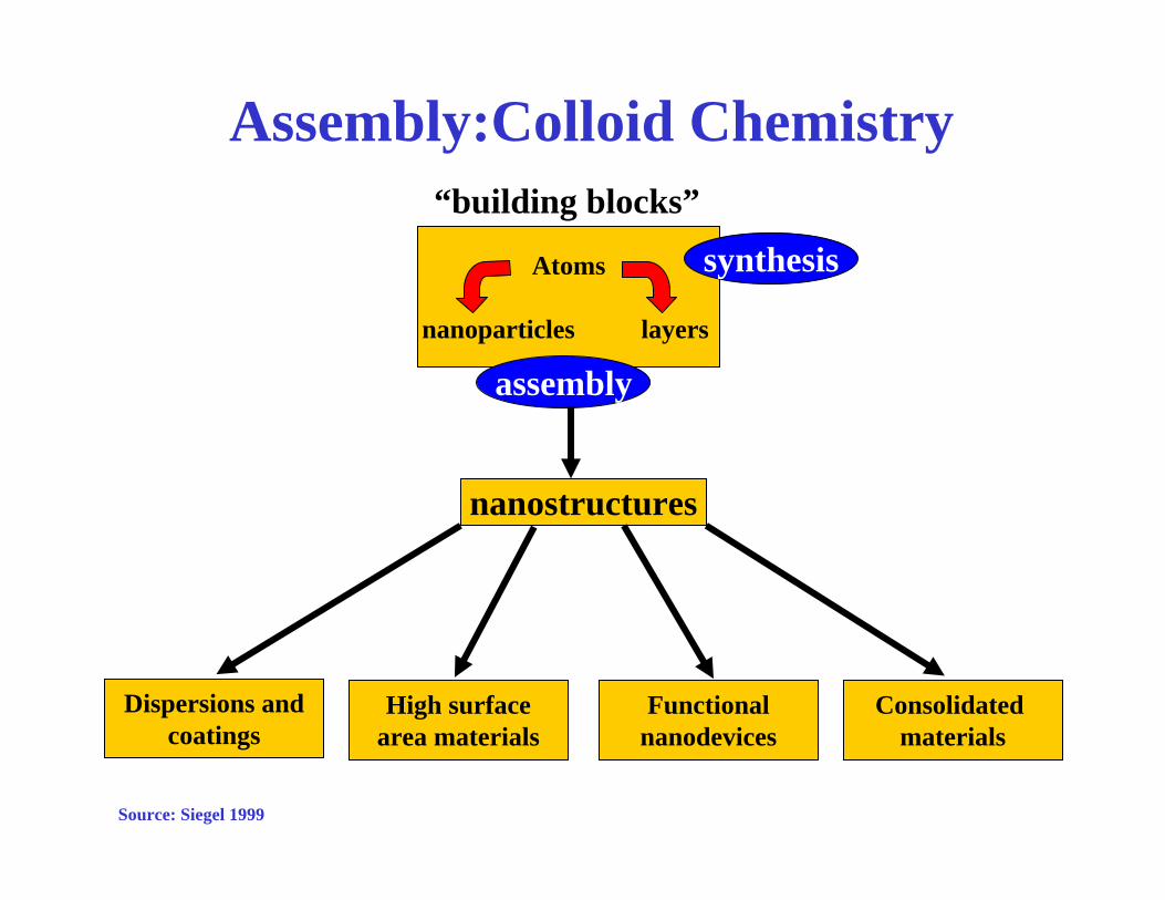
Assembly:Colloid Chemistry
Atoms
nanoparticles layers
nanostructures
Dispersions andcoatings
assembly
“building blocks”
High surfacearea materials
Functionalnanodevices
Consolidated materials
synthesis
Source: Siegel 1999
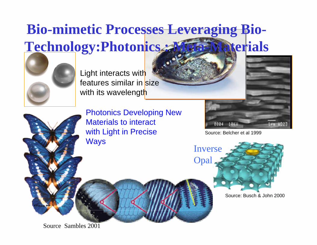
Bio-mimetic Processes Leveraging Bio-Technology:Photonics : Meta-Materials
Source: Belcher et al 1999
Source: Busch & John 2000
Light interacts with features similar in size with its wavelength
Photonics Developing New Materials to interact with Light in PreciseWays
Source Sambles 2001
InverseOpal
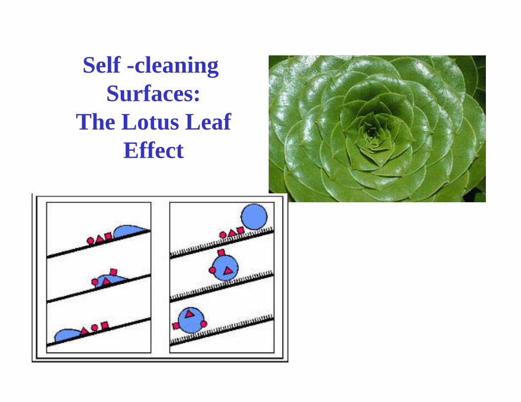
Self -cleaning Surfaces:
The Lotus LeafEffect

Paper Markets
• Advertising– Magazine– Catalogue– Inserts
• Information– Computer output;– ink-jet, EP– Digital Photography
• Packaging– Point of Sale advertising
© Hannah Jones 2001

Suprastar
Coated Paper Surfaces
Capim DG
Carbital 95
Opti-Gloss
Higher SurfacePorosity
Higher SurfacePorosity
Slower Setting
Slower Setting
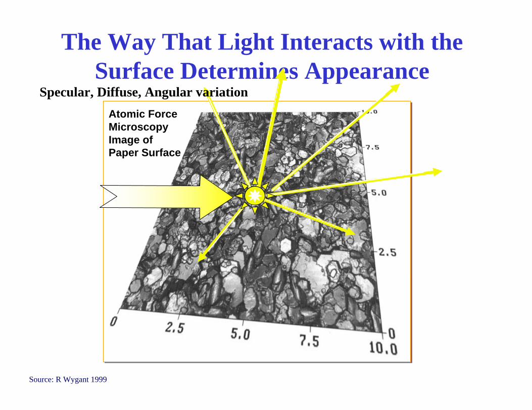
Source: R Wygant 1999
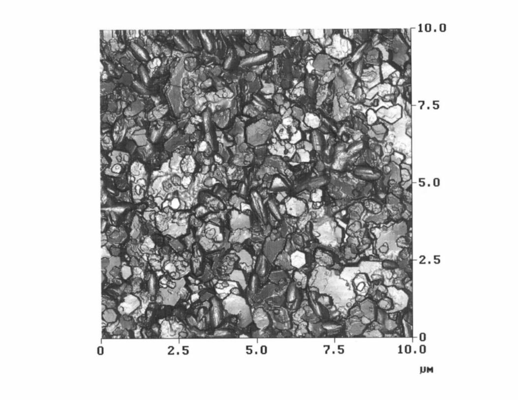
The Way That Light Interacts with the Surface Determines Appearance
Atomic ForceMicroscopyImage ofPaper Surface
Specular, Diffuse, Angular variation


suminagashi
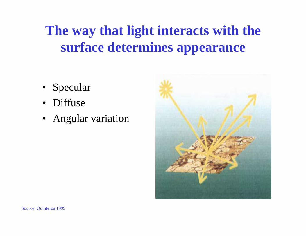
The way that light interacts with the surface determines appearance
• Specular• Diffuse• Angular variation
Source: Quinteros 1999

Gloss vs Surface Roughness
0102030405060708090
100
0 0.1 0.2 0.3 0.4 0.5 0.6
Roughness micron
Tapp
i Glo
ss
20deg45deg60deg75deg85deg
Source D I Lee, 1986 Tappi Coating Conference
0.1 micron = 100 nm

clay +10 pphSBR latex
Prepared cryogenicallyfor SEM
Wetstate
In order to bind, latex particles need to form a film
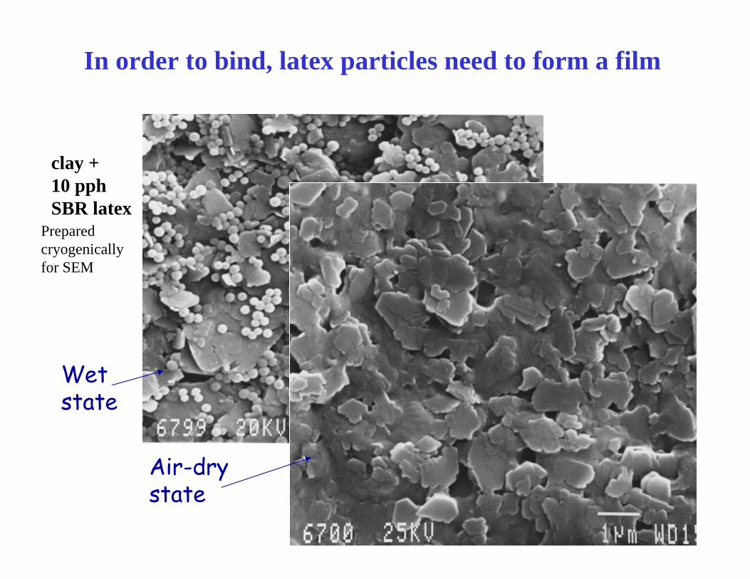
clay +10 pphSBR latex
Prepared cryogenicallyfor SEM
Wetstate
Air-drystate
In order to bind, latex particles need to form a film
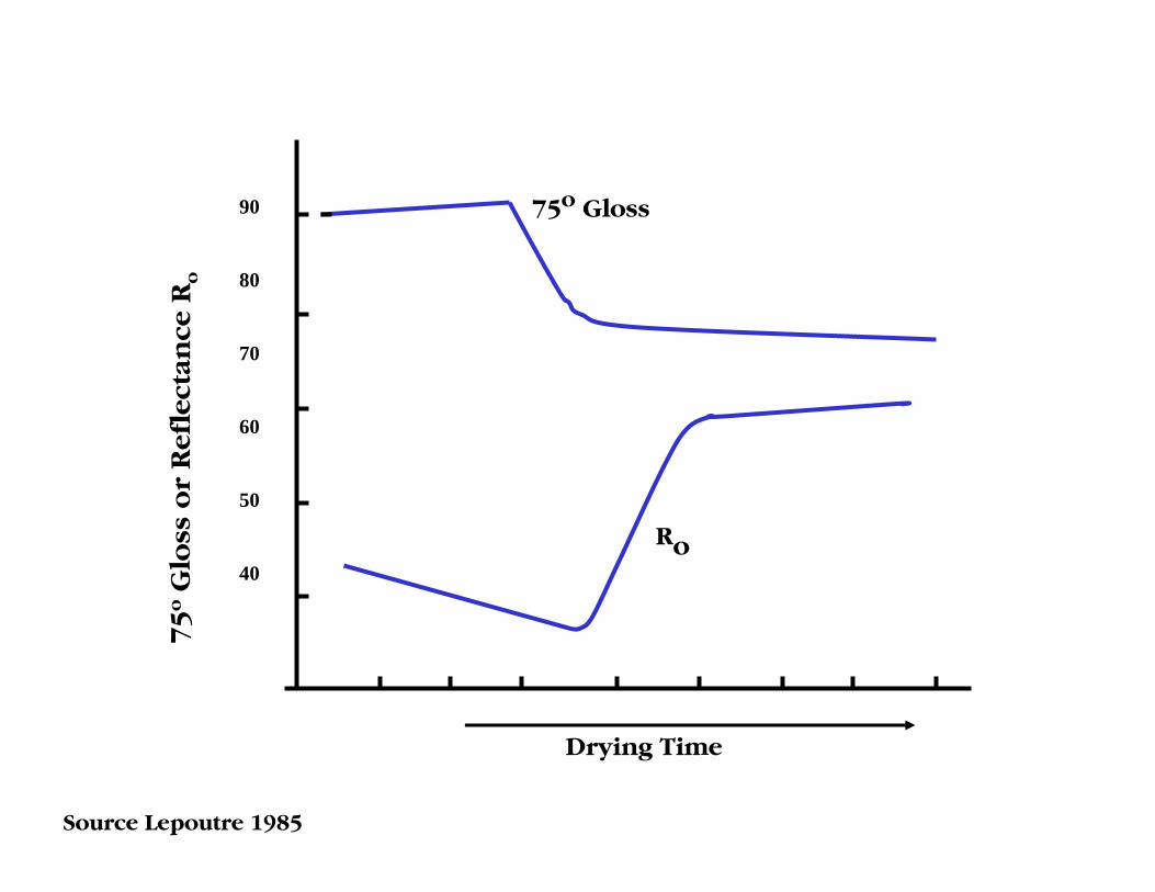
90
80
70
60
50
40
Drying Time
75
oG
loss
or
Ref
l ect
a nce
Ro
75o Gloss
Ro
Source Lepoutre 1985

75
oG
los s
or
Re f
lect
a nce
Ro
Solids volume % Concentration
100
90
80
70
60
50
40
3040 50 60 70 80 90 100
Ro
75o Wet Gloss
GlossFreeze Dried
FCC
SCC
Source Lepoutre 1985
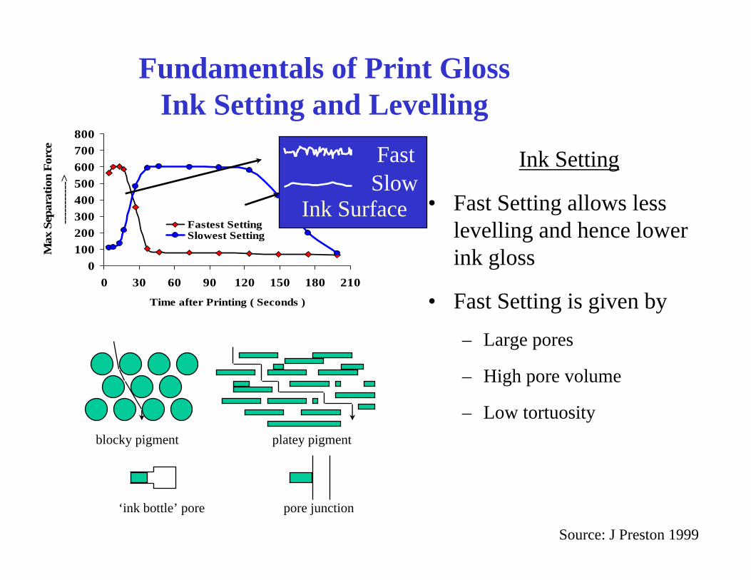
Fundamentals of Print GlossInk Setting and Levelling
Ink Setting
• Fast Setting allows less levelling and hence lower ink gloss
• Fast Setting is given by– Large pores
– High pore volume
– Low tortuosityblocky pigment platey pigment
‘ink bottle’ pore pore junction
0100200300400500600700800
0 30 60 90 120 150 180 210
Time after Printing ( Seconds )
Max
Sep
arat
ion
Forc
e--
----
----
->
Fastest SettingSlowest Setting
FastSlow
Ink Surface
Source: J Preston 1999
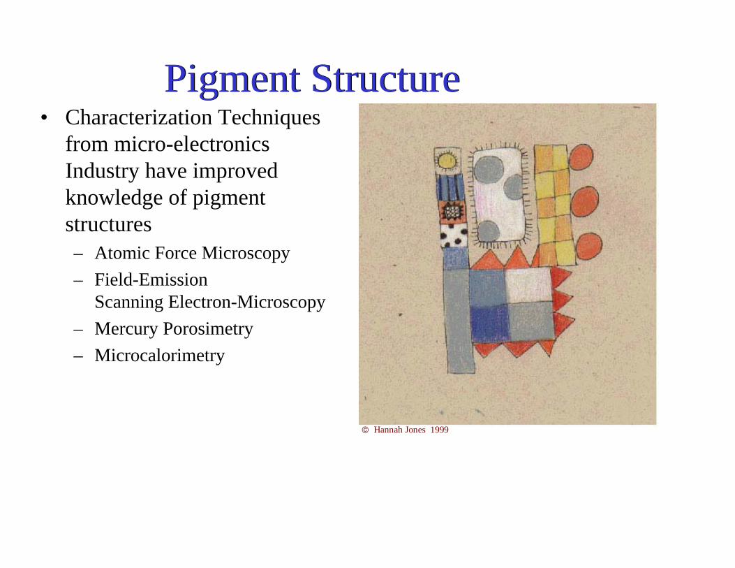
• Characterization Techniques from micro-electronics Industry have improved knowledge of pigment structures– Atomic Force Microscopy– Field-Emission
Scanning Electron-Microscopy– Mercury Porosimetry– Microcalorimetry
Pigment StructurePigment Structure
© Hannah Jones 1999
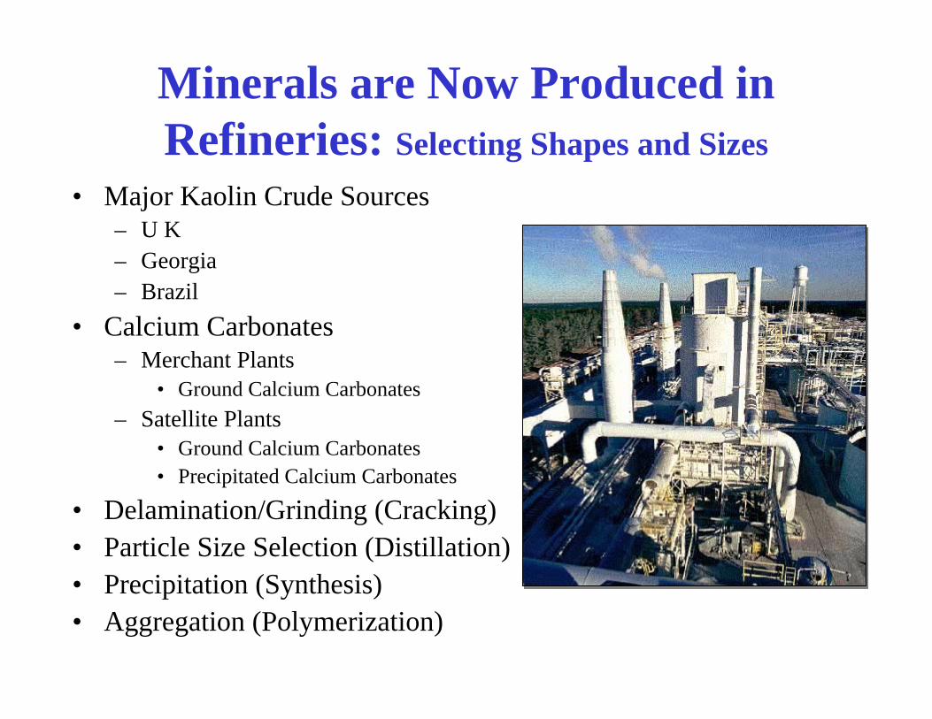
Minerals are Now Produced in Refineries: Selecting Shapes and Sizes
• Major Kaolin Crude Sources– U K – Georgia– Brazil
• Calcium Carbonates – Merchant Plants
• Ground Calcium Carbonates– Satellite Plants
• Ground Calcium Carbonates• Precipitated Calcium Carbonates
• Delamination/Grinding (Cracking)• Particle Size Selection (Distillation)• Precipitation (Synthesis)• Aggregation (Polymerization)
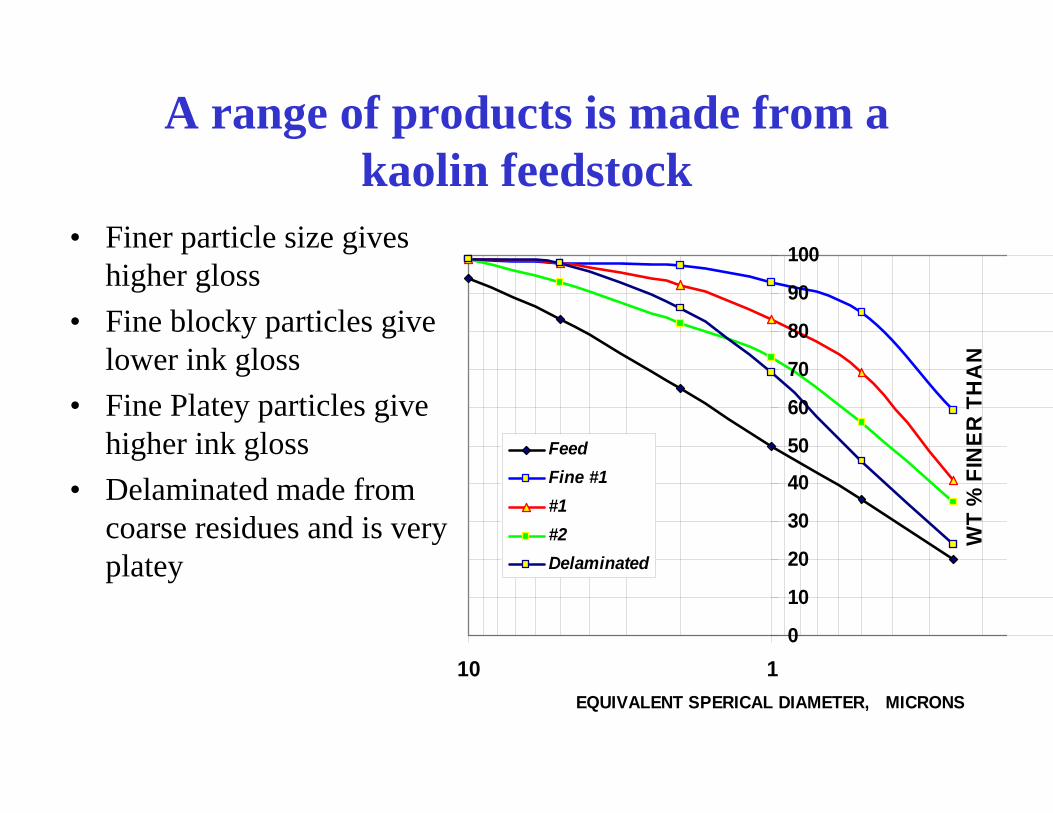
A range of products is made from a kaolin feedstock
• Finer particle size gives higher gloss
• Fine blocky particles give lower ink gloss
• Fine Platey particles give higher ink gloss
• Delaminated made from coarse residues and is very platey
0
10
20
30
40
50
60
70
80
90
100
110EQUIVALENT SPERICAL DIAMETER, MICRONS
WT
% F
INER
TH
AN
FeedFine #1#1#2Delaminated
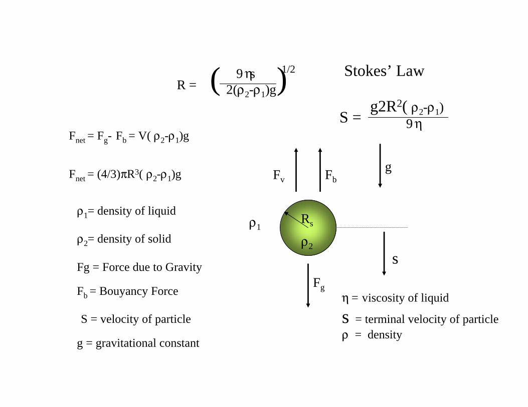
Fb
Fg
gFv
ρ2
ρ1
s
Rs
ρ2= density of solid
Fb = Bouyancy Force
Fg = Force due to Gravity
S = velocity of particle
g = gravitational constant
ρ1= density of liquid
Fnet = Fg- Fb = V( ρ2-ρ1)g
Fnet = (4/3)πR3( ρ2-ρ1)g
R = ( )9 ηs 2(ρ2-ρ1)g
1/2 Stokes’ Law
η = viscosity of liquid
s = terminal velocity of particleρ = density
g2R2( ρ2-ρ1)9 ηS =

ESD: Equivalent Spherical Diameter
C JPEJ 2000O
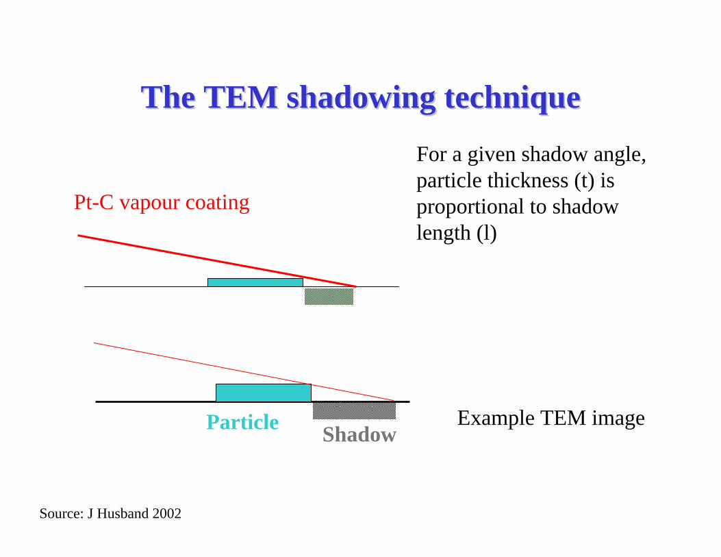
The TEM shadowing techniqueThe TEM shadowing techniqueFor a given shadow angle, particle thickness (t) is proportional to shadow length (l)
Example TEM image
Pt-C vapour coating
Particle Shadow
Source: J Husband 2002

0.05
0.4
1
1.6
2.2
60
120
180
0
20
40
60
80
100
Nano-Mineral Sizes and Shapes
0
5
10
15
20
25
30
0 20 40 60 80 100 120 140 160 180 200 220Crystal Thickness Nanometers
Num
ber
Mine C
Mine AMine B
Crystal Thickness
Shape & Size Distribution
Diametermicron Thickness
nm
Source: R Pruett 1997
Source Golley & Dover 1989
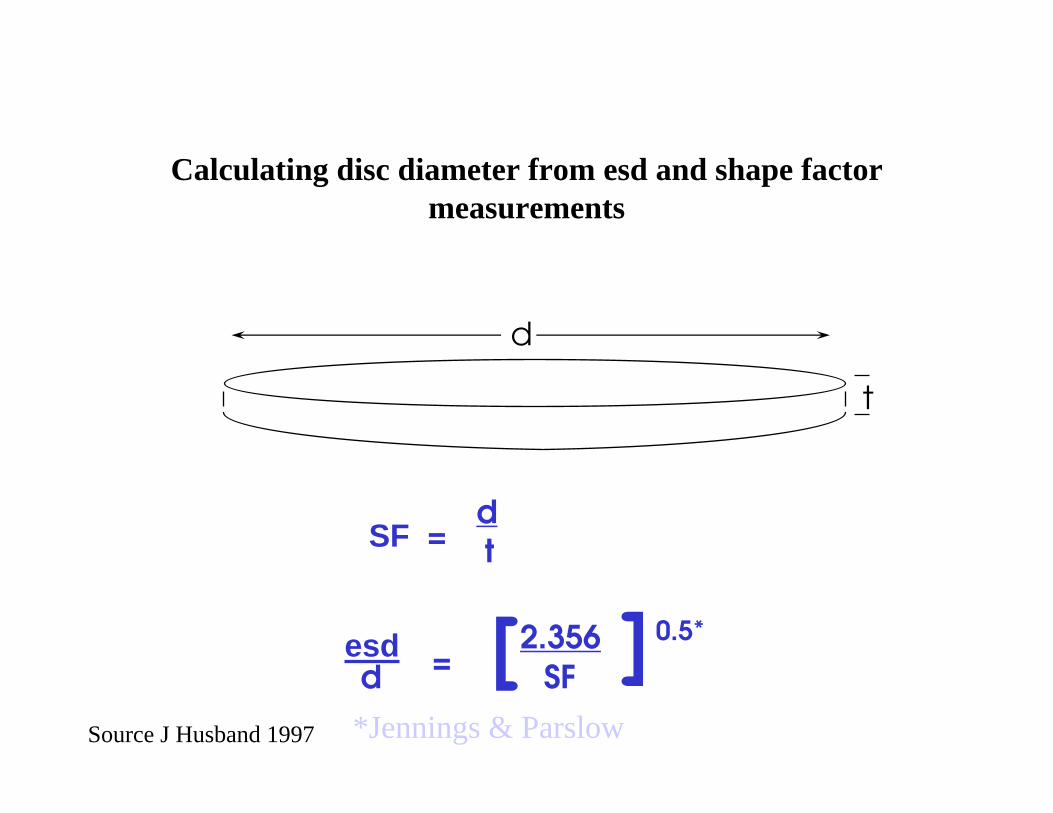
Calculating disc diameter from esd and shape factor measurements
d
t
SF = dt
esdd = [2.356
SF ]0.5*
*Jennings & ParslowSource J Husband 1997
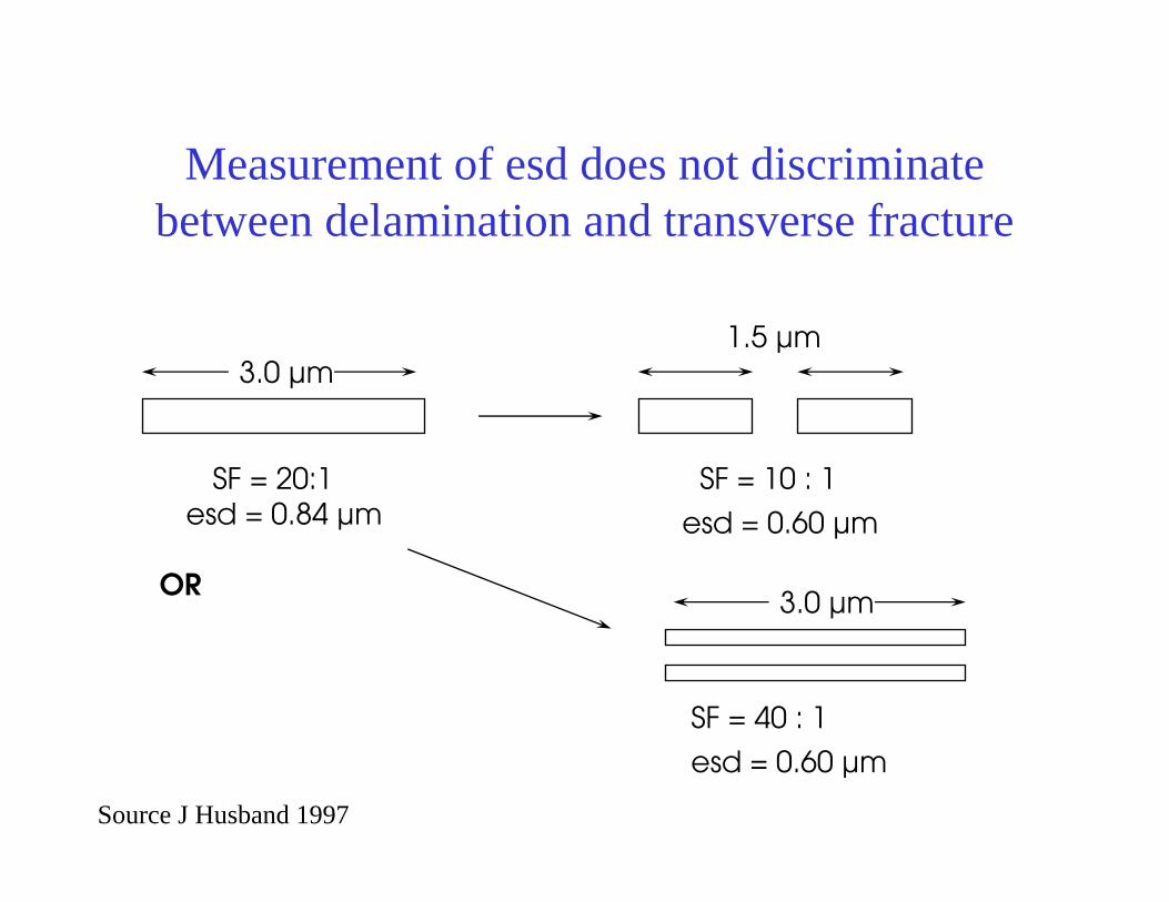
Measurement of esd does not discriminate between delamination and transverse fracture
3.0 µm1.5 µm
SF = 20:1 SF = 10 : 1esd = 0.84 µm esd = 0.60 µm
OR
SF = 40 : 1
esd = 0.60 µm
3.0 µm
Source J Husband 1997
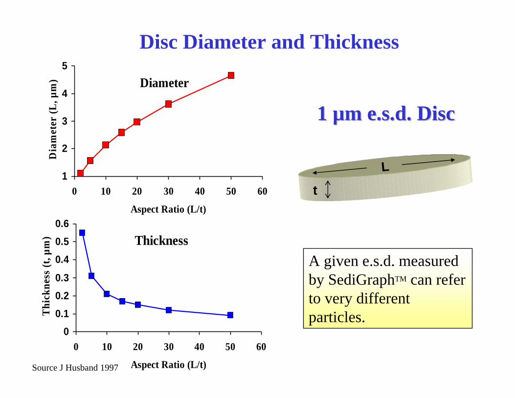
Diameter
1
2
3
4
5
0 10 20 30 40 50 60
Aspect Ratio (L/t)
Dia
met
er (L
, µm
)
t
Thickness
00.10.20.3
0.40.50.6
0 10 20 30 40 50 60
Aspect Ratio (L/t)
Thi
ckne
ss (t
, µm
)Disc Diameter and Thickness
L
1 1 µµm e.s.d. Discm e.s.d. Disc
A given e.s.d. measured by SediGraphTM can refer to very different particles.
Source J Husband 1997

% < 2 μ
Mean ESD μ
ShapeFactor
Diameterμ
Thickness nm
Ultra-FineGlossing
98 0.2 5 0.29 58
Ultra-FinePlatey
98 0.2 45 0.89 19
#2 Clay 80 0.4 10 0.82 82
Delaminated 80 0.55 30 1.96 65
Capim DG 90 0.51 12 1.15 96
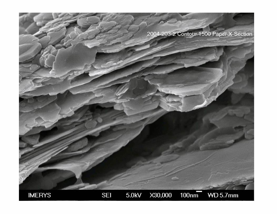
Contour1500
90 0.5 60 2.52 42
Hyperplatey 50 2.0 100 13.0 130
Sedigraph measurements are not the whole story

40
45
50
55
4 5 6 7 8Coat weight gsm
Cal
ende
red
glos
sSuper Platey60:1
Standard delaminated30:1
+8units
Super Platey Clay in 30# offset formulation
Source: Husband: 1999

0.5
0.75
1
1.25
4 5 6 7 8Coat weight gsm
Park
er P
rint S
urf S
moo
thne
ss,
µm
Super Platey60:1
Standard delaminated30:1
1.8 gsm
Super Platey Clay in 30# offset formulation
Source: Husband: 1999
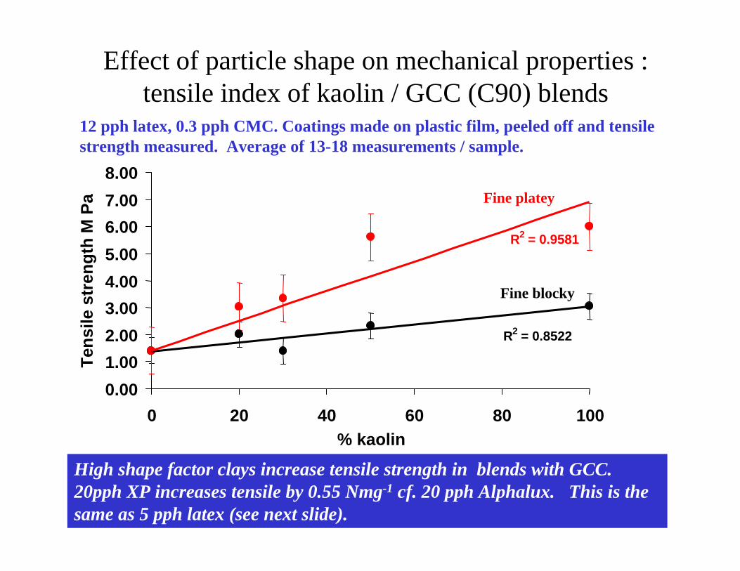
Effect of particle shape on mechanical properties : tensile index of kaolin / GCC (C90) blends
High shape factor clays increase tensile strength in blends with GCC. 20pph XP increases tensile by 0.55 Nmg-1 cf. 20 pph Alphalux. This is the same as 5 pph latex (see next slide).
R2 = 0.8522
R2 = 0.9581
0.001.002.003.004.005.006.007.008.00
0 20 40 60 80 100% kaolin
Tens
ile s
tren
gth
M P
a Fine platey
Fine blocky
12 pph latex, 0.3 pph CMC. Coatings made on plastic film, peeled off and tensile strength measured. Average of 13-18 measurements / sample.
• Self Assembly of building blocks– Optical performance– Ink interactions– Blister Resistance– Dot Shape– Water uptake in Ink-jet– Thermal Barrier for EP
Selection of Shapes and Sizes Building Functional Performance
Selection of Shapes and Sizes Building Functional Performance

Particles and Pores of similar size as wavelength of light
Light of Similar Wavelength as objectLight of Similar Wavelength as object
Light of Similar Wavelength as PoreLight of Similar Wavelength as Pore
Light is diffracted and scattered by
small objects
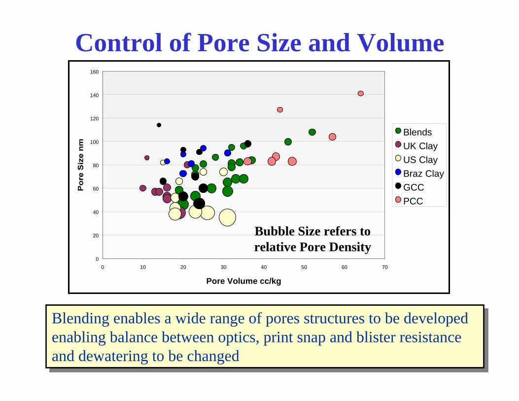
Control of Pore Size and Volume
Blending enables a wide range of pores structures to be developed enabling balance between optics, print snap and blister resistance and dewatering to be changed
Blending enables a wide range of pores structures to be developed enabling balance between optics, print snap and blister resistance and dewatering to be changed
0
20
40
60
80
100
120
140
160
0 10 20 30 40 50 60 70
Pore Volume cc/kg
BlendsUK ClayUS ClayBraz ClayGCCPCC
Bubble Size refers to relative Pore Density

Brightness and Print Gloss with Pigment Blends
70
71
72
73
74
75
76
50 55 60 65 70 75 80Print Gloss 75°
Shee
t Brig
htne
ss IS
O
StandardBlends
EngineeredBlends
OptimisedSolutions
HelicoaterTM Data, 1000m/min, Latex/CMC FormulationData refers to PCC/GCC + US/Brazilian/UK kaolins
Standard Clay-Carbonate blends trade brightness and print gloss.Certain, but not all, Engineered pigment blends offer step changes in
brightness while maintaining high print gloss.
Standard Clay-Carbonate blends trade brightness and print gloss.Certain, but not all, Engineered pigment blends offer step changes in
brightness while maintaining high print gloss.
Optimised Solutions
Opti-Print PCC
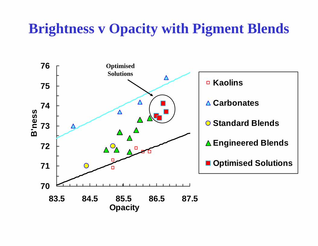
Brightness v Opacity with Pigment Blends
70
71
72
73
74
75
76
83.5 84.5 85.5 86.5 87.5Opacity
B'n
ess
Kaolins
Carbonates
Standard Blends
Engineered Blends
Optimised Solutions
Optimised Solutions

0
0.2
0.4
0.6
0.8
1
0 0.1 0.2 0.3Filler volume fraction
Rel
ativ
e Pe
rmea
bilit
y (P
/Po)
SpheresCylindersPlates A.R. 30 Plates A.R. 100
Platy Minerals as a Barrier MaterialCussler et al. J. Membrane Sci. 231, 1-12
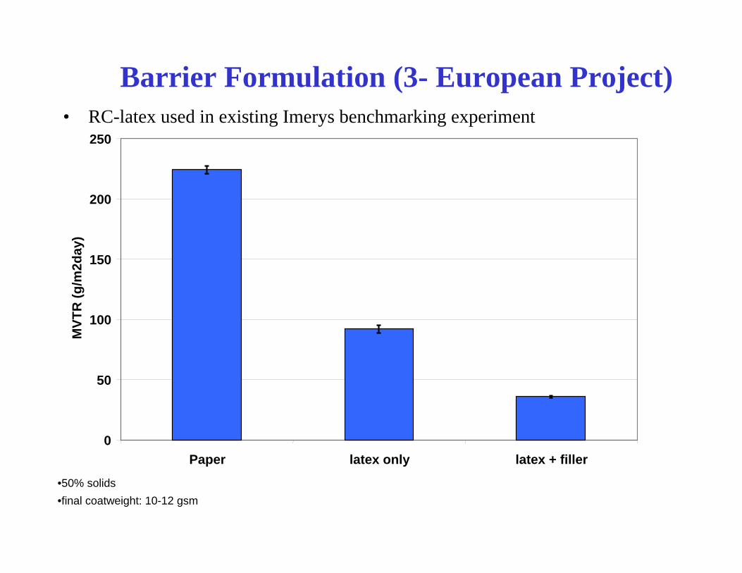
Barrier Formulation (3- European Project)• RC-latex used in existing Imerys benchmarking experiment
•50% solids•final coatweight: 10-12 gsm
0
50
100
150
200
250
Paper latex only latex + filler
MVT
R (g
/m2d
ay)
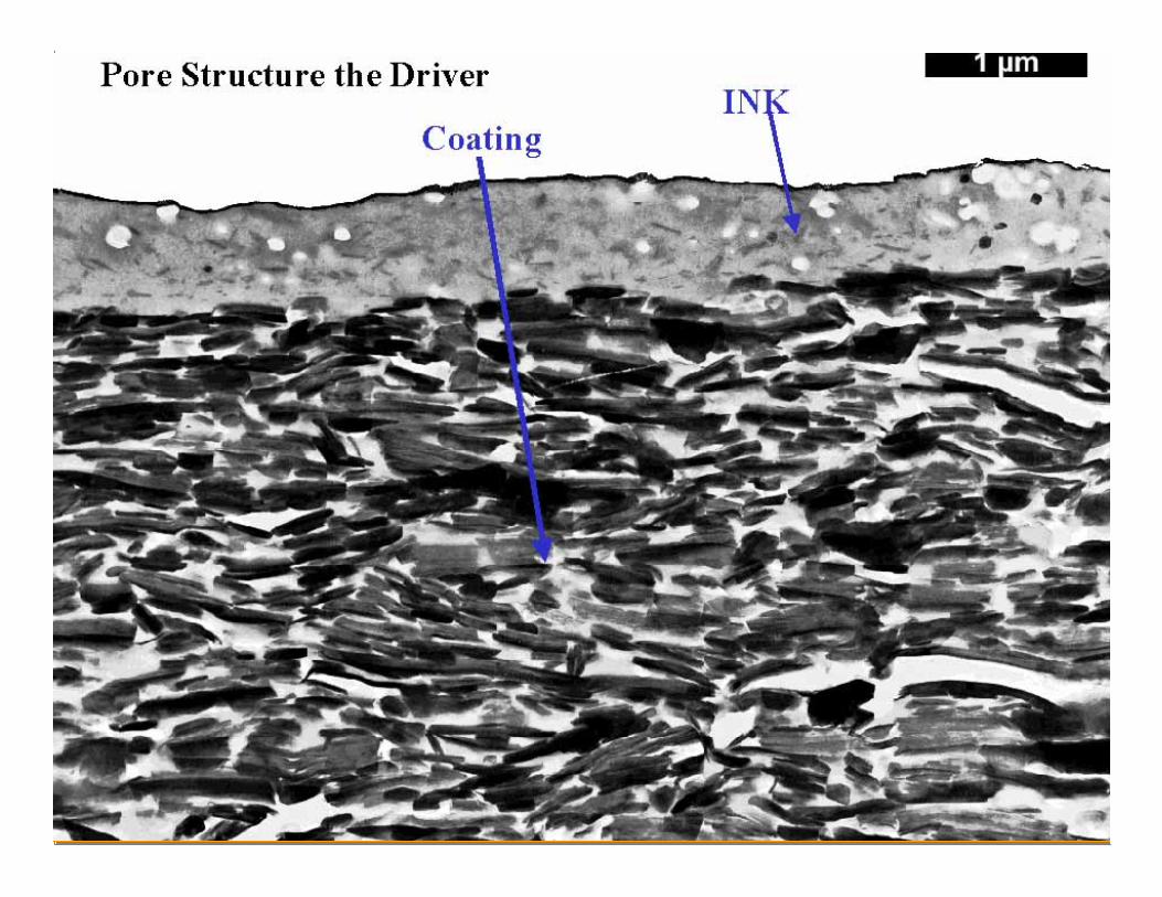
Pore Structure the Drive