nanoscale effects in solid oxide fuel cells - cmu · pdf filenanoscale effects in solid oxide...
TRANSCRIPT

Nanoscale Effects in Solid Oxide Fuel CellsXiao-Dong Zhou and Subhash C. SinghalPacific Northwest National Laboratory

2
Types of Fuel Cells
SOFCMolten
CarbonatePhosphoric
Acid AlkalinePolymer
Membrane
ElectrolyteY2 O3 -
StabilizedZrO2 (YSZ)
Li2 CO3 -K2 CO3 H3 PO4 KOH
Perfluoro-sulfonic
acid
CathodeSr-dopedLaMnO3
Li-dopedNiO Pt on C Pt-Au Pt on C
Anode Ni/YSZ Ni Pt on C Pt-Pd Pt on C
Temperature 750-1000°C 650°C 200°C 100°C 90-120°C
Fuel H2 , CO H2 , CO H2 H2 H2

3
High environmental performance• No SOx or NOx ; Lower CO2 emissions• Quiet• Vibrationless
Solid Oxide Fuel Cells - Advantages
• Coal gas• Naphtha
Fuel flexibility• Liquefied natural gas• Pipeline natural gas
• Methanol• Biogases
Size and siting flexibility• Modularity permits wide range of system sizes• Siting flexibility for distributed power
Cogeneration potential• High quality exhaust heat for heating, cooling, additional power generation
High electric conversion efficiency

4
SOFC Operating Principle2 e-
external electrical load
porous electronicconducting
cathodeLa(Sr)MnO3
dense oxideion conducting
electrolyteYttria-stabilized zirconia (YSZ)
porous electronic
conducting anode
Ni - YSZ cermet
High Po2environment
airO=
Low Po2Environment
fuel(H2 + CO)
Cathode reaction:½ O2 + 2 e- O=
Anode reaction:O= ½ O2 + 2 e-
Oxidation reactions:½ O2 + H2 H2 O + heat½ O2 + CO CO2 + heat
800 to1000°C
Eo = lnPo2(c)Po2(a)
RT4F
The open circuit voltage is given by the Nernst equation:
ln = 1.1 V0.210-18
at 1000°C:RT4F

5
Cell Component Materials
Doped LaCrO3 ; High-temperature alloysInterconnection
Anode
Electrolyte
Cathode
Component
Nickel-YSZ
Yttria-stabilized ZrO2 (YSZ)
Doped Lanthanum Manganite
Material

6
SOFC Designs
Tubular(anode- and cathode-supported; microtubular)
Flattened Tubular(anode- and cathode-supported)
Planar(anode-, electrolyte-, and metal-supported)

7
Tubular vs. Planar Cell Designs
Tubular Cells Planar Cells
Specific Power (W/cm2) Low (0.2-0.35) High (0.6-2.0)
Volumetric Power (W/cm3) Low High
Manufacturing Cost ($/kW) High Low
High Temperature Seals Not Necessary Required
Performance Degradation None 1-4%/1000 hrs

8
SOFC Systems
Hexis 1 kW FCT/SWPC 5 kW
Siemens/Westinghouse 100 kW
Delphi 5 kW APU
Mesoscopic Devices(20 W to 250 W)

9
SOFC Market DriversPositives• Low emissions• High efficiency, even in small size systems• Fuel Flexibility
Negatives• Cost• Cost• Cost• Lifetime• Performance Degradation
10
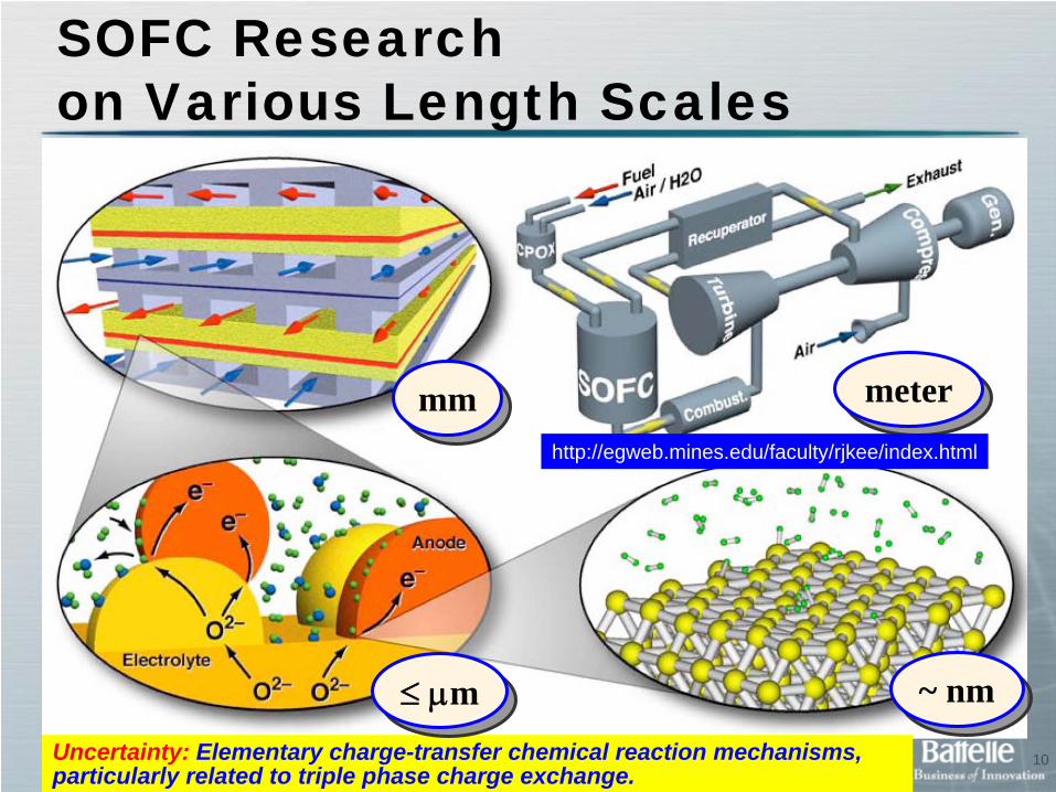
SOFC Researchon Various Length Scales
Uncertainty: Elementary charge-transfer chemical reaction mechanisms, particularly related to triple phase charge exchange.
metermetermmmm
≤ μm≤ μm ~ nm~ nm
http://egweb.mines.edu/faculty/rjkee/index.html

11
Zirconia-Based ElectrolyteVery low electronic conduction (energy band gap: >7 eV)
Very high thermodynamic stability (decomposition PO2 at 1000ºC: <10-35 atm)
Easily doped with lower valence cations (e.g., Ca2+, Y3+, Sc3+, etc.) to create oxygen vacancies
Doped material is highly oxide ion conductive (conductivity: >0.1 Ω-1cm-1 at 1000ºC)

12
Oxide Ion ConductivityTemperature (℃)
1.51.31.10.90.7-5.0
-4.0
-3.0
-2.0
-1.0
0.0
1000/T (/K-1)
5006007008009001000
(ThO2 )0.93 (CaO)0.07
(Bi2 O3 )0.75 (Y2 O3 )0.25
LSGMC(CeO2 )0.9 (Gd2 O3 )0.1(ZrO2 )0.9 (Sc2 O3 )0.1(CeO2 )0.95 (Y2 O3 )0.05(CeO2 )0.9 (CaO)0.1(ZrO2 )0.91 (Y2 O3 )0.09
(ZrO2 )0.85 (CaO)0.15
(ThO2 )0.85 (Y2 O3 )0.15
log(
s/cm
-1)
LSGM
(LSGMC: La0.8 Sr0.2 Ga0.8 Mg0.115 Co0.085 O3 ; LSGM: La0.9 Sr0.2 Ga0.8 Mg0.1 O3 )

13
Nanoionics – Space Charge Model
Grain Boundary
Space Charge
ZoneGrain
Different Charge Transport PathsDifferent Charge Transport Paths
Microcrystalline Materials(Grain size » tgb & tsc )
Grain boundary can act as:Blocking layer at low TEffect is negligible at high T
Nanocrystalline Materials(Grain size ~/< tgb & tsc )
Space charge zone can cover the whole grain, changing mobility of charge carriers.
J. Maier, Prog. Solid St. Chem., 23, 171 (1995); Solid State Ionics, 175 (2004) 7; Nature Materials, 4, 805 (2005).

14
Enhanced Oxygen Diffusivityin Interfaces of Nano YSZ Disk
G. Knoner, K. Reimann, R. Rower, U. Sodervall, and H. E Schaefer, PNAS, 100, 3870 (2003).
18O Diffusion profile analysisBulk and interface diffusion 3order faster in nano than in micro YSZ
Similar magnitude of oxygen exchange coefficient for nano and micro YSZ
~ 60 nm
> 1 mm

15
Ionic Conduction in Nano- crystalline YSZ Films
I. Kosacki et al., Solid State Ionics, 176, 1319 (2005). X. Guo, Acta Mater., 53, 5161 (2005).
MgO YSZ
12 and 25 nm
~ 15 μm

16
17 nm thick films• More excess oxygen in as deposited films;• Increasing oxygen content upon annealing.
17 nm thick films• More excess oxygen in as deposited films;• Increasing oxygen content upon annealing.
427 nm thick films• More oxygen vacancies in as-deposited films• Mechanisms: dopant segregation; surface
oxygen vacancies
427 nm thick films• More oxygen vacancies in as-deposited films• Mechanisms: dopant segregation; surface
oxygen vacancies
Oxygen Content in YSZ Films Determined by RBS and NRA
Oxy
gen
Con
tent
(%)
Annealing Time (hr)

17
Nanosize Effects on Electrolyte Properties• Additives which contribute to ion blocking at grain boundaries are
diluted in nanocrystalline oxides giving rise to substantial reductions in specific grain boundary resistivities. This leads, in some cases, to an overall decrease in grain boundary resistance.
• The case for enhanced ionic conduction in nominally undoped nanocrystalline oxides remains unresolved. In thin films, enhancements of several orders of magnitude are reported. It remains to be seen if this discrepancy is related to differences in the manner in which the dopants are distributed between grain and grain boundary during processing, or, in the case of the films, are due to spurious effects such as humidity or film substrate interactions.
H. L. Tuller, Solid State Ionics, 131, 143 (2000).E. D. Wachsman, MRS Spring Meeting, (2007).

18
Reaction and Length Scalein SOFC Anode
H2
on Ni: 2HH2 ↔
Desorption Rate:2Hddod )θRTEexp(υn~r −
Diffusion of H on Ni: /scm )T1762exp(0.0025D 2H −≈
Diffusion length scale at ~ 700oC: nm20τDt HHd ≈≈
Mean lifetime of chemisorbed H ~ 700oC
ns12θυ
/RT)exp(EτHd
dH ≈=
R. J. Kee, H. Zhu, D. G. Goodwin, Proc. Comb. Institute, 30, 2379 (2005).

19
Improved Anode Performance
YSZ Kim et al, J. Power Sources, 163, 392 (2006).
20
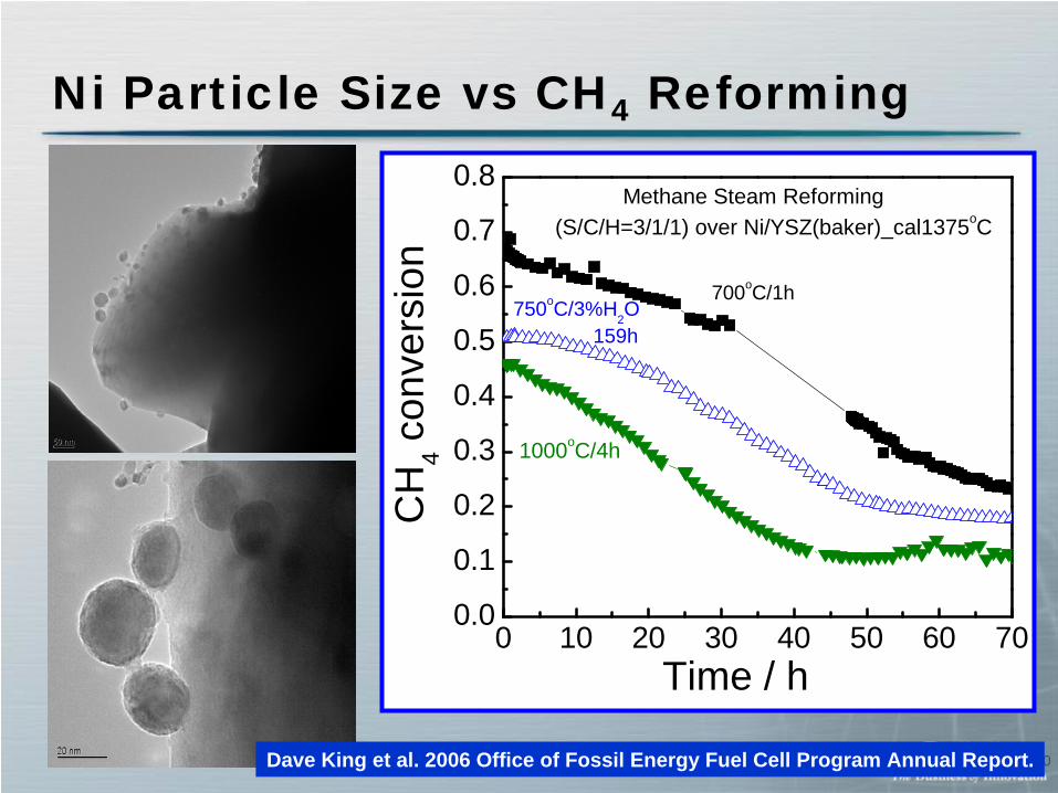
Ni Particle Size vs CH4 Reforming
Dave King et al. 2006 Office of Fossil Energy Fuel Cell Program Annual Report.
0 10 20 30 40 50 60 700.0
0.1
0.2
0.3
0.4
0.5
0.6
0.7
0.8
750oC/3%H2O 159h
1000oC/4hC
H4 c
onve
rsio
n
Time / h
700oC/1h
Methane Steam Reforming(S/C/H=3/1/1) over Ni/YSZ(baker)_cal1375oC

21
Length scale in SOFC cathode
Cathode for Oxygen Reduction
22
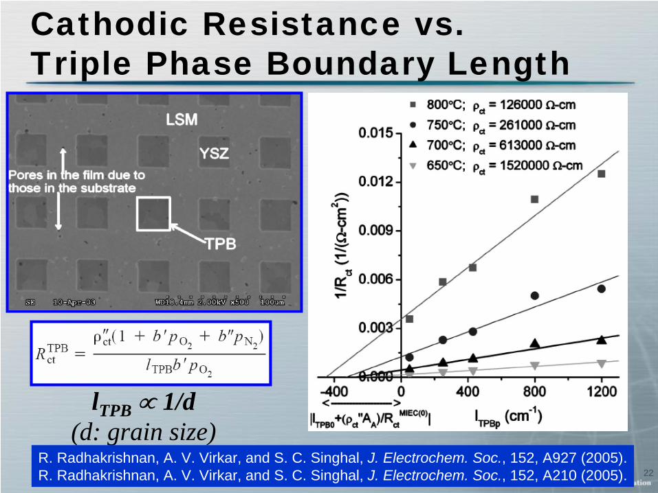
Cathodic Resistance vs.Triple Phase Boundary Length
lTPB ∝ 1/d(d: grain size)
R. Radhakrishnan, A. V. Virkar, and S. C. Singhal, J. Electrochem. Soc., 152, A927 (2005).R. Radhakrishnan, A. V. Virkar, and S. C. Singhal, J. Electrochem. Soc., 152, A210 (2005).

23
Infiltration of Nanoparticles into Cathode
No Infiltration Infiltration w/ Co3 O4
S. Visco, SECA core technology peer review workshop, (2005).

24
Instability of the Cathode
For highly active nanograin cathodes to have stable performance for ~ 40,000 hrs, temperature must be reduced to below 600oC.
For highly active nanograin cathodes to have stable performance for ~ 40,000 hrs, temperature must be reduced to below 600oC.
Instability of dimension and mass is because of loss of lattice oxygen, resulting in more low-valence state transition metal ions.
Instability of dimension and mass is because of loss of lattice oxygen, resulting in more low-valence state transition metal ions.
Line
ar E
xpan
sion
J. Stevenson, PNNL, Unpublished.

25
Improving SOFC Seals
Ron Loehman, www.osti.gov/bridge/servlets/purl/839246-r8KjrS/native/839246.pdf.

26
SummaryMajor impact of nanotechnology in SOFCs• Enhancing ionic conduction in the electrolyte• Decreasing grain size of the electrodes (increasing
surface area) to improve electrocatalysis• Optimizing electronic/ionic conduction paths in electrodes• Optimizing sinterability of the seals
Major Challenges• Stability of the cathode at high operation temperatures• Stability of the anode during cell fabrication• Lowering operation temperature to below 600oC to take
advantage of beneficial effects of nanotechnology