nano@illinois research experiences for teachers...
TRANSCRIPT
nano@illinois Research Experiences for Teachers
(RET)
Photoelectric Effect: Particle Nature of Light Evidence
Ritchie Jatico Lewisville High School
2017-2018

Description:Thismodulestartswithdescribingtheresearchexperienceconductedbytheteacheron2DTMDC’s(TransitionMetalDichalcogenides)forelectronicandphotonicdevicesandrelatethistooneoftheevidencesontheparticlenatureof light-photoelectriceffectwhichtakesplacewhenan incidentlight is shoneonmetal andelectronsare liberated. Studentswill investigate the conceptsbehind thephotoelectriceffectusingan interactivesimulation,ahands-onactivitywheretheybuildamodelthatdemonstratethis lightphenomenon.Throughthese,studentsdevelopingunderstandingontheroleoflight frequency and intensity in the photoelectric effect. Lastly, students will be introduced into anextensionactivitywheretheycreatealightalarmusingtheArduinointerfaceandtheSunFounderUno.Thelessonconcludeswithasummativeassessmentoftheevidenceforlight’sdualnature.
Learning objectives: The student will be able to 1. investigate the particle nature of light energy 2. build a model of the Photoelectric effect 3. make a light alarm using SunFounder UNO and Arduino interface Prerequisite knowledge/skills: This module introduces the particle nature of light and the photoelectric effect. Students should be familiar with the wave nature of light and the following concepts: a. Diffraction b. Electromagnetic spectrum c. Triboelectric effect Note: Students may not need to have coding or programming skills to perform the 3rd task in this model. With adequate teacher guidance and modeling, students should be able to successfully create their light alarm.
Vocabulary: Planck’s constant (h) photoelectric effect work function photon threshold frequency quantum physics detector Crosscutting concepts:
• Light can be modeled as a wave or a particle, depending on the particular behavior being considered.
• The energy of a photon is related to its frequency. Duration: 2- 3 90-minute periods Target grade level(s): 9-12 Target subject(s): Physics (Multiple Levels) AlignmentwithNextGenerationScienceStandards:
• HS-PS4-1 Waves and their Applications in Technologies for Information Transfer Use mathematical representations to support a claim regarding relationships among the frequency, wavelength, and speed of waves traveling in various media.

• HS-PS4-3 Waves and their Applications in Technologies for Information Transfer Evaluate the claims, evidence, and reasoning behind the idea that electromagnetic radiation can be described either by a wave model or a particle model, and that for some situations one model is more useful than the other.
• HS-PS4-4 Waves and their Applications in Technologies for Information Transfer Evaluate the validity and reliability of claims in published materials of the effects that different frequencies of electromagnetic radiation have when absorbed by matter. Background Summary: TMDCs (Transition Metal Dichalcogenides) are a large group of crystals with a generic chemical formula of MX2 (M= transition metal, X = chalcogens such as S, Se, or Te), about two thirds of which are known to form layered structures. There are 88 compositions possible, but theory predicts 44 stable choices. Depending on column of transition metal, we can get wide range of properties: metallic, semiconducting, superconducting, insulating. Semiconducting TMDCs hold promise for a number of applications ranging from photovoltaics, photodetection, optoelectronics, light-emitting diodes, to energy storage/conversion and sensing. Among these 2D semiconductors, MoS2 is the most common and relatively more mature in terms of its synthesis technologies. It has been studied widely for electronics and optoelectronics applications. Considerable efforts have been devoted to the synthesis of controllable, large-scale, and uniform atomic layers of diverse 2D TMDs using various top-down and bottom-up approaches, including mechanical exfoliation and chemical exfoliation. Most of the reported data and theory on the fundamental physics and devices on 2D TMDs have largely relied on the exfoliation method due to its high quality. However, the critical limitations of the flake size and film uniformity have dragged its development beyond the fundamental studies. For this, researchers have used metal-organic-CVD (MOCVD) to obtain high quality TMDs with thickness controllability and wafer-scale uniformity. The 2D materials forming chemical reactions generally use either thermal energy from a heated substrate or non-thermal energy such as microwave or photon energy into the reaction process and the 2D materials forming process depends on lattice parameter of substrates, temperatures, and atomic gas flux. Since this chemical deposition of 2D materials can’t be replicated in a classroom setting, this module aims to introduce one of the evidences of the particle nature of light and illustrate how this has been applied in the manufacture of photonic devices like digital cameras and light sensors. The question of light being a wave or a particle confounded physicists for many centuries. In the 19th century, physicists were fairly certain that light was a wave, because they knew from Young’s double slit experiment that light can diffract and then interfere with itself like water waves. However, light sometimes behaves like a particle. How do we know that light behaves like a particle? The photoelectric effect leads us to this. The wave model could not explain the photoelectric effect which was discovered at the end of the century. When light shines on a polished, unoxidized metal surface, or some other photosensitive materials, electrons can be ejected from the surface of the metal. This is the photoelectric effect, a cornerstone of our understanding of light as a particle. Einstein soon resolved the problem of the photoelectric effect by explaining that light acts as little particles called photons, based on Planck’s equation for their energy, E = hf. They theorized that the energy (E) of each of these photons was proportional to the frequency (f) of the light, or E = hf. In this equation, h is proportionality constant, called Planck’s constant. While light can exhibit wave properties, at the atomic level light often exhibits properties of a particle. It was Einstein’s explanation of the photoelectric effect, not his work on relativity that was honored in his Nobel Prize.
Quantum physics is the study of phenomena at the atomic and nuclear level where many physical properties are quantized, or only come in discrete values. An early success of the quantum theory was in explaining the photoelectric effect through quantized energy of photons. In a photoelectric effect device, light shines on a metal surface and bombards the material’s atoms. Since electrons are on the outermost parts of the atoms, they can be knocked off and removed if the light has enough energy. If the light has more than enough energy to know an electron out of an atom on the surface, the extra energy is used to make the electrons move faster as they leave the surface. Think of being shot in pool with light being the cue ball and the electrons being the pool balls on the outside. Specific Content The Sun’s radiant energy travels to the Earth in the form of electromagnetic waves over a wide band of frequencies. The majority of the Sun’s radiation energy is in the form of infrared, visible, and ultraviolet light. The total power is 1368 W on every square meter of the side of the Earth facing the Sun. The total solar power received by Earth is 1.2×10¹⁷ W or 120,000 TW. By comparison, the total power consumed by humans is about 15 TW. How much energy is in just one of the frequencies present in the Sun’s radiation? The Planck relation, equation, gives the relation between frequency and energy. E = hf E = photon energy (J) h = Planck constant = 6.63×10⁻³⁴ J s f = frequency (Hz)
The constant of proportionality is called Planck’s constant, named after the German physicist Max Planck, who inferred its properties in 1900. Planck’s constant connects the energy of electromagnetic radiation to its frequency. Its value is 6.63×10⁻³⁴ J s. This equation might appear straightforward, but it actually represents a fundamental change in scientific thought! Planck’s relation describes a universe where light’s energy only comes in discrete packets called the photon. There is no bundle of light energy smaller than hf—all larger quantities of light energy are made up of whole number multiples of hf. When Planck—and later Albert Einstein—thought about light as being composed of little bundles of energy, they changed the way we think of light. Planck’s constant is of the order of 10−34. The Planck equation affects matter and energy on the microscopic scale. A photon of visible light energy is a tiny quantity, appropriate to the size and energy of a single atom. The photon is an example of quantum physics. The word quantum means a physical quantity that occurs only in discrete units, or bundles. A photon is a quantum of light energy. A quantum cannot be divided. A single photon is the smallest possible quantity of light. You cannot have half of a photon or 1.5 photons. Light occurs in integer multiples of whole photons. Hertz in 1887 discovered that an ultraviolet light source shining on a metal’s surface would increase electrical sparks—later recognized to be electrons ejected from the metal—across the gap between two metal plates. The photoelectric effect occurs when illuminating a metal surface with light ejects electrons.

Subsequent researchers showed several curious results. Lower frequency light, such as red light, never liberated electrons no matter how bright the light source. Higher frequency light, such as ultraviolet light, would always eject electrons no matter how faint the light source—although the number of electrons varied with the intensity of the light. In classical physics it was assumed that light was an electromagnetic wave, which meant that the energy of the ejected electrons should be a function of the intensity and frequency of the light, not just frequency. What was wrong with this picture? There was another property of the photoelectric that was difficult to explain with the wave model for light from classical physics. In the wave model, low-intensity light would take some time to deposit enough energy to cause the electrons to vibrate sufficiently to break free from their atoms. But the observational results showed that electrons were immediately released, no matter how faint the incident light. This lack of a delay time for low-intensity light confounded the classical physicists! Albert Einstein in 1905 explained the photoelectric effect with two insights. First, he assumed that light was composed of quantized photons, each with its own, indivisible bundle of energy. Second, the atoms in the metal held onto their electrons with a binding energy called the work function. Only if the photon’s energy was high enough to exceed the work function would an electron be ejected. Since Planck had already proposed a photon’s energy to be related to its frequency, the minimum energy of the work function corresponded to a threshold frequency for electrons to be ejected. How much energy do the ejected electrons have? Part of the energy of the incident photon liberates the electron from the metal; the remainder of the photon’s energy is converted into kinetic energy of the electron. The photon energy required to liberate the electron is called the work function. The kinetic energy of the electron is therefore the difference between the incident photon energy and the work function of the metal, as given by equation below. The work function is a property of the metal; different metals have different values for their work function. Ek = hf – W0 Ek = maximum energy of ejected electron (J) h = Planck’s constant = 6.63×10⁻³⁴ J s f = frequency of incident light (Hz)
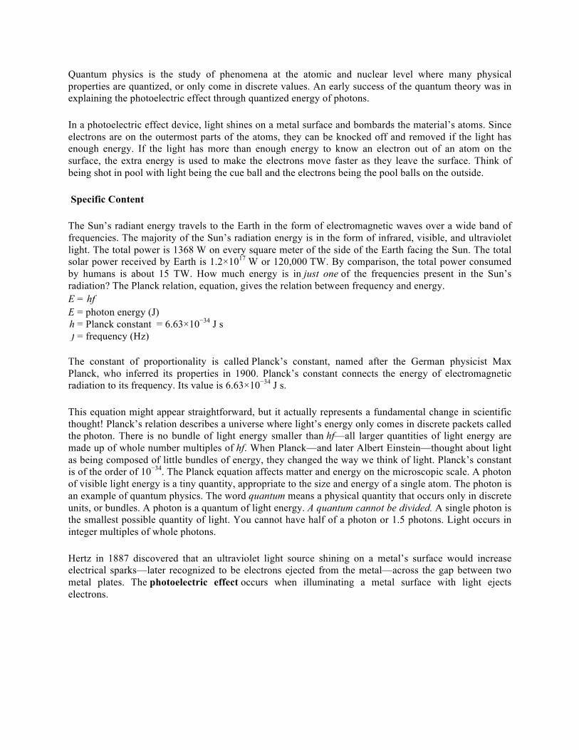
W0 = work function for metal (J) The value for the work function of a material is usually very small, on the order of 10−19 J. Because of this, it is convenient to use a different unit of energy to express the work function. The electron volt is a unit of energy that is used to express changes in energy on an atomic scale. One electron volt is equal to 1.602×10⁻¹⁹ J. Einstein’s explanation for the photoelectric effect required light to act as a particle, not a wave. Is there any other evidence for the particle nature of light? In 1916, Einstein predicted that photons have momentum. Arthur Compton tested the prediction by scattering x-rays off of electrons.The scattered x-rays decreased in energy, while the recoiling electrons increased in energy and momentum. To conserve total momentum in the collision, the photons must have momentum—a property of particles! The Compton effect further demonstrated that light can act as a particle.
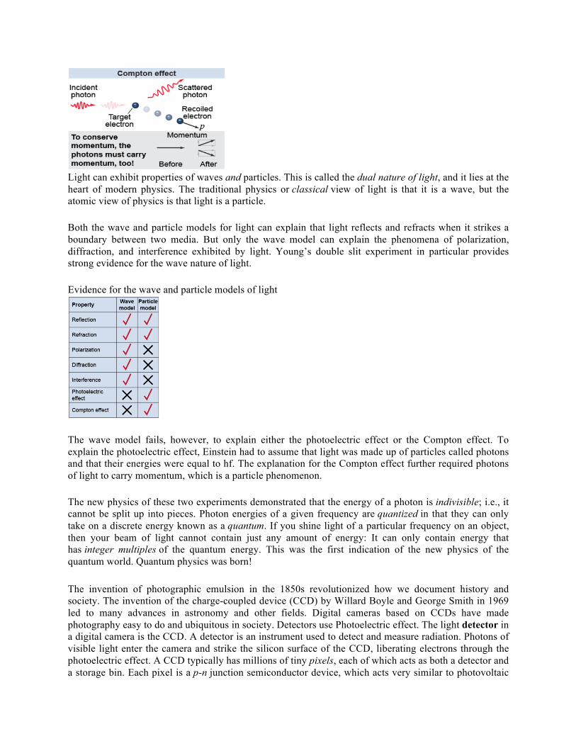
Light can exhibit properties of waves and particles. This is called the dual nature of light, and it lies at the heart of modern physics. The traditional physics or classical view of light is that it is a wave, but the atomic view of physics is that light is a particle. Both the wave and particle models for light can explain that light reflects and refracts when it strikes a boundary between two media. But only the wave model can explain the phenomena of polarization, diffraction, and interference exhibited by light. Young’s double slit experiment in particular provides strong evidence for the wave nature of light. Evidence for the wave and particle models of light
The wave model fails, however, to explain either the photoelectric effect or the Compton effect. To explain the photoelectric effect, Einstein had to assume that light was made up of particles called photons and that their energies were equal to hf. The explanation for the Compton effect further required photons of light to carry momentum, which is a particle phenomenon. The new physics of these two experiments demonstrated that the energy of a photon is indivisible; i.e., it cannot be split up into pieces. Photon energies of a given frequency are quantized in that they can only take on a discrete energy known as a quantum. If you shine light of a particular frequency on an object, then your beam of light cannot contain just any amount of energy: It can only contain energy that has integer multiples of the quantum energy. This was the first indication of the new physics of the quantum world. Quantum physics was born! The invention of photographic emulsion in the 1850s revolutionized how we document history and society. The invention of the charge-coupled device (CCD) by Willard Boyle and George Smith in 1969 led to many advances in astronomy and other fields. Digital cameras based on CCDs have made photography easy to do and ubiquitous in society. Detectors use Photoelectric effect. The light detector in a digital camera is the CCD. A detector is an instrument used to detect and measure radiation. Photons of visible light enter the camera and strike the silicon surface of the CCD, liberating electrons through the photoelectric effect. A CCD typically has millions of tiny pixels, each of which acts as both a detector and a storage bin. Each pixel is a p-n junction semiconductor device, which acts very similar to photovoltaic

cells used in solar arrays. In a CCD, each pixel acts as a capacitor, where electric fields keep the electrons in place until it is time to read out the picture. The accumulated charge in a pixel corresponds to the number of photons that were incident upon the pixel and liberated an electron. An amplifier converts the charge of the stored electrons into a voltage that is read and stored. If more photons strike a pixel, then it stores more electrons and results in a higher voltage when the pixel is read out. The CCD shifts the charge for the first row’s pixels one by one across the serial register to the amplifier where the voltage is read out. The CCD then shifts the remaining pixels down by a row and reads out the second row’s pixels one by one. In this way the CCD creates an image of the number of photons detected in each pixel. Preparation time:
• For the Interactive simulation – 90 minutes • For the Model-making activity- 60 min • For the Building of the Light Alarm using SunFounder Uno with Arduino- 90 min • For the Assessment- 20 min
Preparation notes for materials and chemicals: This module introduces evidence for the particle nature of light, the Photoelectric effect. In the photoelectric effect, incident light is shone on metal and electrons are ejected. Students will first use an interactive simulation to explore the role of frequency and intensity in the Photoelectric effect. It will then be followed by an activity involving use of common materials to build a model that demonstrates Photoelectric effect and lastly an application activity where students use Sunfounder kits to create a light alarm. Day 1: A. Slide Presentation : “ Nanotechnology and Photoelectric Effect” - Teacher will relate the research conducted on TMDC’s by presenting the video on the synthesis of Two-Dimensional materials and their heterostructures, emphasize the potential applications of the nanomaterials and relate this to the lesson on particle nature of light and the coming activities. Key terms, and key concepts will be frontloaded during the presentation as well as the mathematical formulas invovled. The presentation will introduce the evidence on the particle nature of light and relates the frequency of a photon to its energy using Planck’s relation. Einstein’s explanation for the photoelectric effect, along with Compton scattering, provide evidence of the particle nature of light. The presentation will also explain the application of the photoelectric effect in digital cameras and how this will be observed in the activity where students build a light sensing alarm using Arduino interface and SunFounder Uno. During presentation and discussion, teacher will have students create a table that lists down the evidences on the duality nature of light. B. Photoelectric Effect Simulation - Teacher will demonstrate how the simulation can be accessed using their technology (IPAD or smartphones). It must be noted that this simulation is not in HTML but JAVA supported. Students will use the interactive simulation from https://phet.colorado.edu/en/simulation/photoelectric to investigate the way in which the frequency and intensity of incident photons determine their ability to eject electrons from various metals. The students will find that the incident photons must have frequencies equal to or greater than the “threshold frequency” in order to have enough energy to eject electrons. Even very high-intensity light below this frequency threshold cannot eject electrons. Students are encouraged to complete the assignment sheet independently while using the simulation and then discuss their answers with a partner. Teacher will bring the class together to discuss findings.

Day 2: C. Photoelectric effect Model - Teacher will break into manageable sections this activity. Prior to building the model that demonstrates Photoelectric effect, students are given instructions and shown the video in building an electroscope using this link https://rimstar.org/equip/electroscope.htm. I have used and adopted the information resource for this activity from, https://rimstar.org/science_electronics_projects/photoelectric_effect.htm. In this activity, students shine UV light on a zinc metal plate and observe that electrons are emitted from the zinc. The effect is observed by its effect on the charged leaves of an electroscope. The leaves start out being charged and spread apart, but after 2 minutes and 26 seconds the photoelectric effect has discharged the leaves and they're together again. Day 3: D. Building a light alarm - Teacher will show student leaders how to download the file Super Kit V3.0 for Arduino.zip from the SunFounder website by visiting LEARN-> Get Ttutorials -> Super Kit V3.0 for Arduino and unzip the files. Teacher must also provide the background information about Arduino such as it being an open source platform with simple software and hardware that provides an integrated development environment for code compiling, compatible with multiple control brands as well as the different parts of the kit that will be used. Videos on various interesting projects using Arduino may be shown such as this one from https://www.youtube.com/watch?v=eJg3yuAAawA&t=14s to the students prior to this activity to spark interest and creativity for future projects. If possible, only provide the materials/components from the kit that are needed for this activity. Since the components include very small parts, it is suggested that these parts are placed in small plastic bags with labels before handing out to the student groups. Safety: All standard laboratory safety practices should be followed and adult supervision should be present at all times. A. Modeling Photoelectric Effect * Teacher must review all the standard lab safety practices with the students. The following must be observed:
• Take all necessary steps to reduce the exposure time to as short as is reasonably achievable. • Limit access to areas where the UV black lights are used. Limit time and distance when working
with UV-producing equipment. • Post warning signs at the entrance to labs or other work areas using UV light. • Require students to wear protective eyewear and gloves. Nitrile gloves are recommended, but
other hazards also need to be considered in choosing the correct glove. Glasses should wrap around and be ANSI-Z87 rated. Normal eyeglasses/contacts offer very little protection!
• Require students to wear lab coat and long pants. Have students cover arms and neck and limit exposure time. Face Shield – is preferred as it protects more skin area. People commonly forget to protect their chin and neck.
B. Building a Light Alarm
• Students should be reminded to plug/unplug the parts gently and appropriately. Overpowering operations may cause damage to the product and injury.
• Students are advised that while the kit is made for SunFounder boards and works with the corresponding official boards, the manufacturer does not guarantee the kits are compatible with

other brands, thus students must consult with teacher before using other components not prescribed in the lab.
• Students are advised to not expose the SunFounder kits to water/moisture or heat from any sources, or place it on conductive surfaces while in operation.
Waste disposal:
• “Black light” lamps should be disposed of in the same manner as office fluorescent lamps. In most states, fluorescent and compact fluorescent light bulbs used at home can be disposed of in the same way as regular light bulbs. While all fluorescent bulbs contain a trace amount of mercury, the quantity is so minute that disposal is not regulated by federal standards (established by the EPA, the Environmental Protection Agency). You would have to dispose of an incredibly large amount of fluorescent bulbs — around 360 4-foot fluorescent tubes — before you would be subject to federal disposal standards. However, individual states and provinces also have established disposal standards, so you should check the disposal policies in your area. Materials/supplies/equipment needed with example source listed/pricing/CAS # and contact information. A. Building Photoelectric Effect Model Material Price/ Amount Supplier/ Link Teacher Note UV lamp $18.83 Amazon
https://goo.gl/MUBjQ8
-use UV fluorescent lamp which gives off UV-A and UV-B light
Zinc metal plate $7.10 Amazon https://goo.gl/EQDZ3G
Frey Scientific Zinc Electrode Strip, 5" Length x 3/4" Width x 3/64" Thick
Glass jar with nonconductive cover (plastic)
can be found at home
Metal wire like copper wire $6.95 Ward’s Science+ https://goo.gl/aGjYJX Item # 470104-608
Wire, Bare Copper, 20 Gauge, 25 m, 113 grams
Aluminum foil for metal leaves
can be found at home
Sand paper or steel wool $4.27 per package The Home Depot https://goo.gl/6fRtpT Model # 19036-20-CC Internet #202563276
3-2/3 in. x 9 in. 150 Grit Fine Grade Sand Paper (6-Sheets/Pack)
2 stacks of book or boxes can be found at home

B. Building a Light Sensing Alarm using Arduino interface Material Price/ Amount Supplier/ Link Teacher Note SunFounder Project Super Starter Kit V3.0 + Mega with Tutorial Book for Arduino UNO R3 Mega 2560
$47.99 Amazon https://goo.gl/9EG3oy
This kit contains most of the components needed for the project and it also contains 113 page instructions book
SunFounder New Uno R3 For Arduino ATMEGA328P ATMEGA16U2
$11.99 Amazon https://goo.gl/iYViTF
Arduino Compatible UNO R3 board
Procedure/activity:
A.InteractiveSimulation
Name: __________________
PhET simulation: Photoelectric Effect
Essential questions: How does the photoelectric effect depend on the frequency and intensity of the incident light? Why does it require a quantum physics explanation? Background: Nineteenth century physicists uncovered a most peculiar interaction between light and matter that they called it photoelectric effect. Light shining on a metal will liberate electrons, creating electric current. Lower frequency light, however, does not liberate electrons—no matter how bright the source of the light. Why would a faint but blue light source create electric current while an intense red light source would not? In this investigation you will recreate the photoelectric effect in an interactive simulation. Directions: * Access the PHET lab at phet.colorado.edu * Click on Play With Simulations on the upper left of the screen * Click Physics, and under Quantum, click Photoelectric effect Objectives – In this interactive simulation, you will be able to : a. investigate the Photoelectric effect. b. observe the properties of the light that cause electrons to be liberated from the metal. c. relate the mathematical formulas of Photoelectric effect to the determination of Energy.

You can change the intensity of the incident light, its frequency, and the kind of metal it is shining upon. Part1:Thresholdfrequency
1. Launch the interactive simulation. Select calcium. 2 . Increase the intensity of the light source (default color is violet) to around 50% so that electrons are
ejected from the metal surface. 3 . Change the light to different wavelengths - such as red light or ultraviolet - and observe the changes
to the ejected electrons. 4 . Repeat this test for three other metals.
Questions:
a. Does UV light eject electrons? Green light? Red?
b. The threshold frequency is the minimum frequency of a photon that can eject an electron from the surface. Record your measured threshold frequencies in Table 1. Are electrons ejected at lower or higher frequencies than this threshold?
c. Above the threshold frequency, how does the electron speed change with frequency?
Table1:Thresholdfrequenciesforvariousmetals.
Metal
Thresholdfrequency,f0(Hz)
Workfunction,W0(J)
Table2:Electriccurrentfortwodifferentfrequenciesabovef0.Metaltested:___________
Frequency
(Hz)
Electriccurrent(mA)
0s
5s
10s
15s
20s
25s
30s
Average

d. Above the threshold frequency, how does electric current change with frequency? Choose a metal to test. Collect and tabulate current data every 5 s for 30 s for two different frequencies above the threshold value. Record your data in Table 2 above. Refer to this data to support your answer.
e. Below is the table that lists the threshold frequencies for photoelectric emission for various metals. Source: CRC, 76th Edition, 12: 122-124.
Do your values agree with the experimentally measured values?
Part2:Intensityofthelight
1. Set the frequency above the threshold. Observe the ejected electrons as you vary the light intensity.
2 . Set the frequency below the threshold. Observe the ejected electrons as you vary the light intensity.
Questions:
a. How does the number of ejected electrons vary with light intensity above the threshold frequency?
b. How does the number of ejected electrons vary with light intensity below the threshold frequency?
c. Above the threshold frequency, how does the electron speed change with the light intensity?
d. Why does the photoelectric effect require a quantum explanation? In your answer, refer to the threshold frequency and the effect of changing the intensity of the light.
e. Summarize your results for frequencies above the threshold frequency:
Abovef0,whenthelightintensityincreases...
thenumberofejectedelectrons(increases)(decreases)(remainsthesame)
the kinetic energy of ejected electrons (increases) (decreases) (remains the same)

Abovef0,whenthelightfrequencyincreases...
the number of ejected electrons (increases) (decreases) (remains the same)
the kinetic energy of ejected electrons (increases) (decreases) (remains the same) Applying new knowledge
1. Whatistheenergyofonephotonoflightoffrequency5.45×1014Hz?
2. Whichhasmoreenergy,aphotonoffrequency1.2×1012Hzoroneoffrequency3.7×1011Hz?Whatistheratiooftheirenergies?
3. Howmanyphotonsoffrequency7.0×1014Hzaretherein1Joflightenergy?
4. What does the slope in the Energy (eV) vs Frequency graph? How do write the equation for this graph?
5. Calculatetheworkfunctionforeachmetalyoutested,andrecordthevaluesinTable1oftheinvestigation.Theworkfunction,W0,equalstheenergynecessarytoknockanelectronloosefromagiventypeofmetal,soW0=hf0.
6. What is the importance of this investigation?

B.ModelingPhotoelectricEffect
GroupMembers:__________________________Date:________________Grade:______________
ModelingPhotoelectricEffect
Objective:tobuildamodelanddemonstratethePhotoelectriceffect.
Background:ThePhotoelectriceffectiswhereelectronsareemittedfromcertainmaterialswhenlightofacertainminimumwavelengtharrivesatthematerial.
Materials:
• UVlamp• 1Zincmetalplate• 2Aluminumleaves• 12inch14gauge(AWG)copperwire• 2blocksofwoodorstacksofbooks• glassjarwithnonconductiveplasticlid• blackelectricaltape• plastictubeorstraw• apieceofvinyl(suchasvinylwindowblinds)
A.BuildingaDIYElectroscope
AnElectroscope isadevicethatcanbeusedtogetanideaofhowmuchelectricalchargeisonanobject.Byitself, it can’t tell you if anobject is negatively chargedorpositively charged,or give youanumerical value forquantityofchargebutitwilltellyouifitischarged.Ifyouhavetwochargedobjects,itmaytellyouifoneismorechargedthantheother,basedonhowmuchtheleavesintheelectroscopemoveapart.
Steps:1.CuttwopiecesofAluminumfoilintothesametearshapeorrectangularshapeandputholeinoneendofeach.2.Cutabout12inchofcopperwireandspiraloneendtomakealargesurfaceareatoholdthezincmetalplate.3.Shoveaplastictubeandshoveitthroughthelidandhotgluetokeepitstable.4.Toassemble,takethecopperwireandstickitthroughthetube.5.Formtheotherendofthecopperwireintoaroundlittlehook.6.CarefullyputtheAluminumfoilthruitsholeonthehookandslipitinwithoutbreakingthewhole.Taketheotherpieceofaluminumfoilandputitthrough.Theyshouldbenowtouchingtogetherattheendofthehook.7.Withabout4piecesofelectricaltape,putthemonthelidwiththecopperwireandslipthesetupoverthetopoftheglassjar,benddowntheelectricaltape.8.Cutsomemoreofblackelectricaltapeandtapeitaroundthelidtoreinforcetheothertapetomakesurethatitholdsonwell.B.TestingtheDIYElectroscope1.Takeapieceofvinyl,rubitandmovethispiececlosetotheexposedandspiralendofthecopperwire.2.Watchwhathappenstothealuminumfoilleaves!Theleavesshouldspreadapart.C.InductivelyChargingtheElectroscope1.Chargeupacleanglasswithapositivechargebyrubbingitwithavinyl.2.Bringtheglassnearthezinc,butnottouchingit.3.Whilestillholdingtheglassclosetothezincplate,touchanyofthemetalonthe
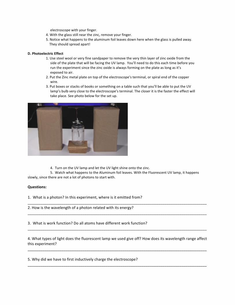
electroscopewithyourfinger.4.Withtheglassstillnearthezinc,removeyourfinger.5.Noticewhathappenstothealuminumfoilleavesdownherewhentheglassispulledaway.Theyshouldspreadapart!D.PhotoelectricEffect1.UsesteelwoolorveryfinesandpapertoremovetheverythinlayerofzincoxidefromthesideoftheplatethatwillbefacingtheUVlamp.You’llneedtodothiseachtimebeforeyouruntheexperimentsincethezincoxideisalwaysformingontheplateaslongasit’sexposedtoair.2.PuttheZincmetalplateontopoftheelectroscope’sterminal,orspiralendofthecopperwire.3.Putboxesorstacksofbooksorsomethingonatablesuchthatyou’llbeabletoputtheUVlamp’sbulbveryclosetotheelectroscope’sterminal.Thecloseritisthefastertheeffectwilltakeplace.Seephotobelowforthesetup.
4.TurnontheUVlampandlettheUVlightshineontothezinc.5.WatchwhathappenstotheAluminumfoilleaves.WiththeFluorescentUVlamp,ithappensslowly,sincetherearenotalotofphotonstostartwith.Questions:1.Whatisaphoton?Inthisexperiment,whereisitemittedfrom?_____________________________________________________________________________________2.Howisthewavelengthofaphotonrelatedwithitsenergy?_____________________________________________________________________________________3.Whatisworkfunction?Doallatomshavedifferentworkfunction?_____________________________________________________________________________________4.Whattypesoflightdoesthefluorescentlampweusedgiveoff?Howdoesitswavelengthrangeaffectthisexperiment?_____________________________________________________________________________________5.Whydidwehavetofirstinductivelychargetheelectroscope?_____________________________________________________________________________________

6.WhendoesPhotoelectriceffecthappenandhowdoesthePhotoelectriceffectwork?_____________________________________________________________________________________7.HowisPhotoelectriceffectdemonstratedinthisexperiment?Hint:ThinkaboutwhathappenedtotheAluminumfoilleavesafterturningontheUVlampandshiningittotheplate. _____________________________________________________________________________________8.Createaconceptmap(suchasaflowchart)ofthekeyeventsduringPhotoelectricEffect.Belowisatemplate/example.Addasmuchdetailsasyoucan.
C.CreatingaLightAlarm
Name:_______________________________Date:___________________Grade:_______________
CreatingaLightAlarm
OBJECTIVES-Studentswillbeableto:
a.describethephotoelectriceffect.
b.explaintheessentialcomponentsneededtoconductthisexperimenttostudythephotoelectric
effect.
Note:Inthisexperiment,theLEDwillnotbrightenuntilyoushinestronglightonitthusenergizingthetransistor.Sothisexperimentshouldbetterbedoneinadarkenvironment.
MATERIALS:
-1*SunFounderUnoboard
-1*Breadboard
-1*USBcable
-Jumperwires
-1*Passivebuzzer

-1*Resistor(10KΩ)
-1*LED
-1*NPNTransistorS8050
Step1:PREPARETHECOMPONENTS
Step2:KNOWTHEPRINCIPLE
Theschematicdiagram
LEDsdemonstratephotoelectriceffect.Theywillgenerateweakcurrentswhenexposedtolightwaves.
Alarmsarewidelyusedindifferentaspectsinourdailylife.Theyhighlydecreasethepropertylossesandsecurityrisks. Inthisactivity,wemakea lightalarm. It involvesaDIYphototransistor.DIYphototransistorsusethegloweffectandphotoelectriceffectofLEDs.Thatis,LEDswillgenerateweakcurrentswhensomelightisshoneonit.Andweuseatransistortoamplifythecurrentsorsignalgenerated.Thetransistorwillinputtheamplifiedcurrentto SunFounderUnoboard viaportA0, thebuzzer toportD5ofUnowill beepand LEDonport12will lightupunderahighlevelsotheSunFounderUnoboardcandetectthem.

NPNtransistorsareeasytouse.NPNconsistsofa layerofP-dopedsemiconductor(the"base")betweentwoN-dopedlayers(seethepictureabove).TheleftpinisEmitterelectrode,attachedtothepowersource,themiddlepinisbase,andtheredpinisthecollector.
Asmallcurrententeringthebaseisamplifiedtoproducealargecollectorandemittercurrent.Thatis,whenthereisapositivepotentialdifferencemeasuredfromtheemitterofanNPNtransistortoitsbase(i.e.,whenthebaseishighrelativetotheemitter)aswellaspositivepotentialdifferencemeasuredfromthebasetothecollector,thetransistorbecomesactive.Inthis"on"state,currentflowsbetweenthecollectorandemitterofthetransistor.Ifonly themiddle pin has weak trigger currents, they will flow from left to right of the LED like a switch beingopened.
Therearethreepolesfortheregions:base(b),emitter(e)andcollector(c).TheyformtwoP-Njunctions,namelythe base-emitter junction and collector-base junction. The arrow in the NPN symbol (see the figure below)indicatesthedirectionofthebase-emitterjunction.
The symbol of NPN is shown here.We can see the two PN junctionswith unilateral conductivity inside,whichenablesitaswitchcomponent.
A10kΩpull-downresistor isattachedtothetransistoroutputstage inordertoavoidanalogportsuspendingtointerferewithsignalsandcausemisjudgment.
Step3:BUILDTHECIRCUIT
a.Placetransistoronbreadboard.
b.Connectaresistortocollectorelectrodeofthetransistor.

c.Connecttheotherendoftheresistortoground.
d.PlaceanLEDonthebreadboard.
e.Connectitsanodetobaseelectrodeofthetransistor.
f.Connectitscathodetoground.
g.Connectemitterelectrodeofthetransistorto5Vpowersource.

h.Connectthepositiveelectrodeofthebuzzertothepin5ofSunfounderboard.
i.Connectthenegativetoground.
j.ConnectthecollectorelectrodetoA0oftheboard.
k.Connecttheboardandthebreadboard.
Afterbuildingthecircuitboard,startprogramming.
STEP4:PROGRAMANDUPLOADTHECODE
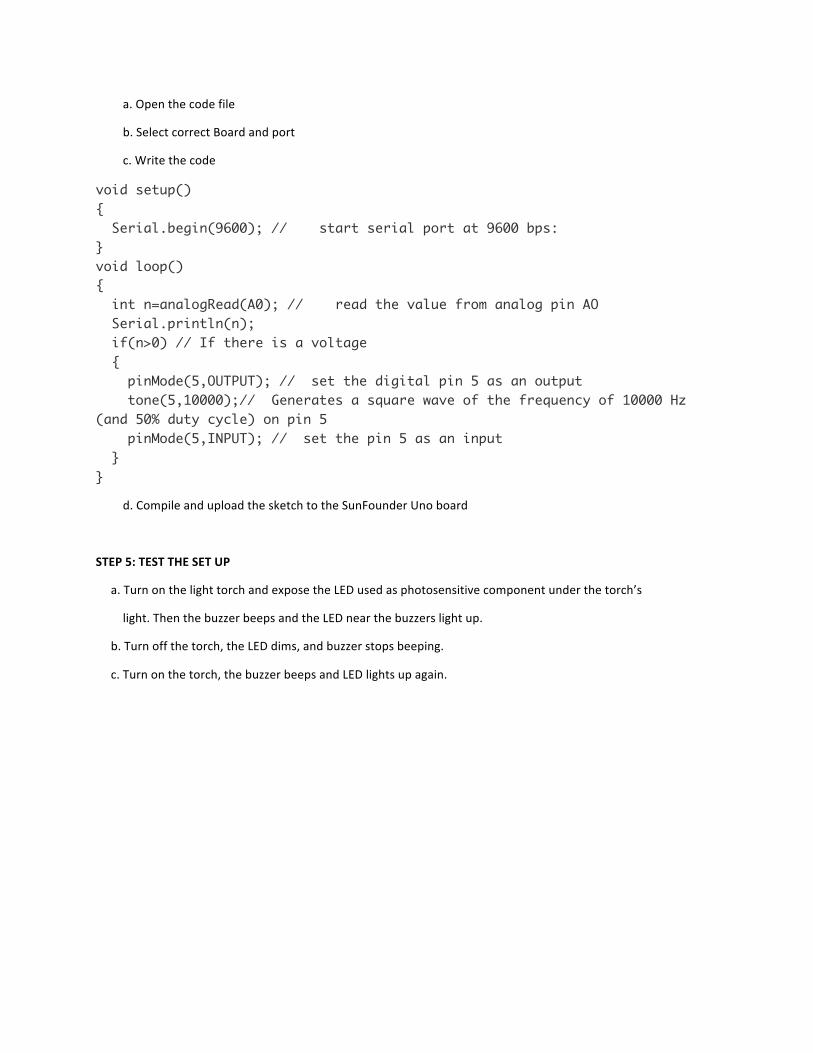
a.Openthecodefile
b.SelectcorrectBoardandport
c.Writethecode
void setup() { Serial.begin(9600); // start serial port at 9600 bps: } void loop() { int n=analogRead(A0); // read the value from analog pin AO Serial.println(n); if(n>0) // If there is a voltage { pinMode(5,OUTPUT); // set the digital pin 5 as an output tone(5,10000);// Generates a square wave of the frequency of 10000 Hz (and 50% duty cycle) on pin 5 pinMode(5,INPUT); // set the pin 5 as an input } }
d.CompileanduploadthesketchtotheSunFounderUnoboard
STEP5:TESTTHESETUP
a.TurnonthelighttorchandexposetheLEDusedasphotosensitivecomponentunderthetorch’s
light.ThenthebuzzerbeepsandtheLEDnearthebuzzerslightup.
b.Turnoffthetorch,theLEDdims,andbuzzerstopsbeeping.
c.Turnonthetorch,thebuzzerbeepsandLEDlightsupagain.

Presentationtalkingpoints:
Slides 1 -3: Teacher will introduce the research on 2D Transition Metal Dichalcogenides to provide students with background information on current researches in the field of Nanotechnology, a glimpse into the complex equipment and processes involved, insights on the nature of the work of scientists and connection on the role that light plays in the potential applications of these materials. Terms will be frontloaded here and a video of the actual research experiment done in the lab with MOCVD will be shown. Slide 4 - 6: Teacher presents the probing questions on some of the properties of light. Slide 7-10: Teacher presents the Photoelectric effect puzzle including the historical background of its discovery. Students describe the photoelectric effect; students learn why wave model for light does not explain the photoelectric effect, leading to the dual nature of light. Slides 11-13: Teacher presents Einstein’s ideas on the particle nature of light. Students explain the impacts of the scientific contributions of a variety of historical scientists on scientific thought. Slides 14-16: Teacher presents the idea about energy of a photon by introducing the mathematical formula that relates light frequency and energy in the Planck relation, named after Max Planck who inferred about particle property of light. Practice questions are also introduced here. Students investigate the relationship between frequency and energy of a photion Slides 17-20: Teacher relates the Planck’s relation with the Kinetic Energy concepts and introduces the term and the ideas that led to Quantum physics. Slides 21-22: Teacher presents another evidence that supports the particle nature of light- The Compton effect Slides 23: Teacher presents a table that summarizes the evidences for the dual nature of light. Slides 24-25: Teacher presents one of the common application of Photoelectric effect- digital cameras

Links to the research articles and other resources: 1. Dufresne, S. (2012). Photoelectric effect experiment and how it works. Retrieved March 31, 2018, from https://rimstar.org/science_electronics_projects/photoelectric_effect.htm 2. H.S. Lee, S.-W. Min, Y.-G. Chang, M.K. Park, T. Nam, H. Kim, J.H. Kim, S. Ryu, S. Im, “MoS2 nanosheet phototransistors with thickness-modulated optical energy gap”, Nano Lett., Vol. 12, pp. 3695-3700 , 2012 3. Hsu, T., Chaniotakis, M., & Pahre, M. (2014). Essential Physics. Ergopedia. 4. J.A. Wilson, A.D. Yoffe, “The Transition metal dichalcogenides discussion and interpretation of the observed optical, electrical and structural properties”, Adv. Phys., Vol. 18, pp. 193-335, 1969 5. “Lesson 16 Simple Creation - Light Alarm.” SunFounder, SunFounder, 2012, www.sunfounder.com/learn/lesson-16-simple-creation-light-alarm-super-kit.html. 6. M. Bernardi, M. Palummo, J.C. Grossman, “Extraordinary sunlight absorption and one nanometer thick photovoltaics using two-dimensional monolayer materials”, Nano Lett., 13 , pp. 3664-3670, 2013 7. “Photoelectric Effect.” PhET, University of Colorado- Boulder, 1 Feb. 2016, phet.colorado.edu/en/simulation/photoelectric#for-teachers-header [Acknowledgement: Thank you to my research mentor, Kai Xu, my faculty mentor, Wenjuan Zhu, for the feedback during the summer RET, for Terry Koker and Kelly Jolley for sharing your ideas and resources with us, to fellow teacher participants for the company and collaboration, and to the project managers Dr. Irfan Ahmad and Dorothy Gordon for providing us the opportunity to participate in this exciting program and to the technical staff at the Micro and Nanotechnology Lab, and Center for Nanoscale Science and Technology support.]
Financial support was provided by the National Science Foundation under grant #NSF EEC 14-07194 RET, as part of the nano@illinois project, through the University of Illinois Center for Nanoscale Science and Technology and the Micro and Nanotechnology Lab at the University of Illinois at Urbana-Champaign. This work, which includes teacher and student resources, is licensed under a Creative Commons Attribution-Noncommercial-Share Alike 3.0 Unported License. To view a copy of this license, visit: http://creativecommons.org/licenses/by-nc-sa/3.0/. To attribute this work, please use [“R. Jatico. Title (Date).”]
The nano@illinois Research Experience for Teachers (RET) at the University of Illinois at Urbana-Champaign (from 2014-2017) exposes a diverse set of in-service and pre-service science, technology, engineering, and mathematics (STEM) teachers and community college faculty from across the nation to cutting-edge research in nanotechnology. The RET focuses on recruiting underrepresented minority populations (focused on ethnicity, geography, disability, and veteran status) including women and will target teachers from high-need areas, including inner city, rural, low-income, and those with significant URM students. Participants conduct research over 6 weeks in world-class labs with 4 follow-up sessions during the school year.
Teacher professional development opportunities includes teacher-focused lectures, mentoring, networking, poster sessions, ethics seminars, hands-on modules, STEM education issues, career choices, and resources for implementing a nano lab and curriculum. Teachers will develop modules to be disseminated widely and present their results. High-quality follow-up sessions and evaluation will be infused.
The nano@illinois Research Experiences for Teachers (RET) is managed by the University of Illinois Center for Nanoscale Science Technology.
Center for Nanoscale Science and Technology 208 N. Wright, MC-249 Urbana, Illinois 61801
217-244-1353 [email protected]
www.nano.illinois.edu