naming and addressing for routing · pdf file · 2011-09-02the current interdomain...
TRANSCRIPT

JOHNS HOPKINS APL TECHNICAL DIGEST, VOLUME 30, NUMBER 2 (2011)168
INTRODUCTIONThe current interdomain routing system for the
Internet, based on the Border Gateway Protocol (BGP), achieves scalability by exploiting address hierarchy and summarizability. However, multihoming (MH), traffic engineering (TE), and mobility between networks are threatening the hierarchical address aggregation and are already pushing the BGP routing tables to the limit. Although both the commercial Internet and the network of networks (as envisioned for the Global Information Grid) used by the DoD exhibit a topological hierarchy,
the Global Information Grid’s end devices and edge networks have a much higher degree of mobility. The Global Information Grid also has greater needs for TE and MH. The DoD network involves a backbone based on commercial Internet standards and uses several layers of mobile ad hoc networks in its tactical edge. These edge networks are used for ground-, sea-, and air-based wireless communication on the move. Wired and satel-lite connections allow these tactical networks to access the backbone. It should be noted that the end devices
Naming and Addressing for Routing Scalability
Lotfi Benmohamed, Robert G. Cole, and Bharat T. Doshi
he current interdomain routing model for the Internet suffers from the over-loading of Internet Protocol addresses and their use for identification, loca-
tion, and forwarding. This overloading makes it hard to adequately sup-port multihoming, traffic engineering, and mobility while maintaining address hierarchy, which is essential for scalable routing. We identify architectural and protocol changes in addressing and routing that are needed to provide major improvements in scalability. In particular, we propose a protocol solution based on separation of identification and addressing and a mechanism for mapping identifiers to addresses. Solutions proposed earlier address the need for either multihoming and traffic engineering or mobility. Our solution addresses all three needs. We also developed a model to evaluate the performance and scalability of our mapping system. We conducted a performance study using real Internet traffic traces to drive the model. The results of this study are presented in this article.
JOHNS HOPKINS APL TECHNICAL DIGEST, VOLUME 30, NUMBER 2 (2011) 169
from the perspective of the shared infrastructure. Later, we will see how this situation is very similar to the sepa-ration of ID and address we propose.
This article is organized as follows: Routing Scalability introduces the reasons behind the scalability problem and Scalable Solution presents our proposed solution. Solution Properties discusses the solution properties and compares these properties with those of other solutions. The article concludes with Performance Evaluations and Conclusions.
ROUTING SCALABILITY The main architectural problem with the current
interdomain routing model is the overloading of IP addresses in the sense that they are used for identifica-tion, location, and forwarding. To understand how this overloading affects the scalability of routing, let us look at the topology of the Internet carefully.
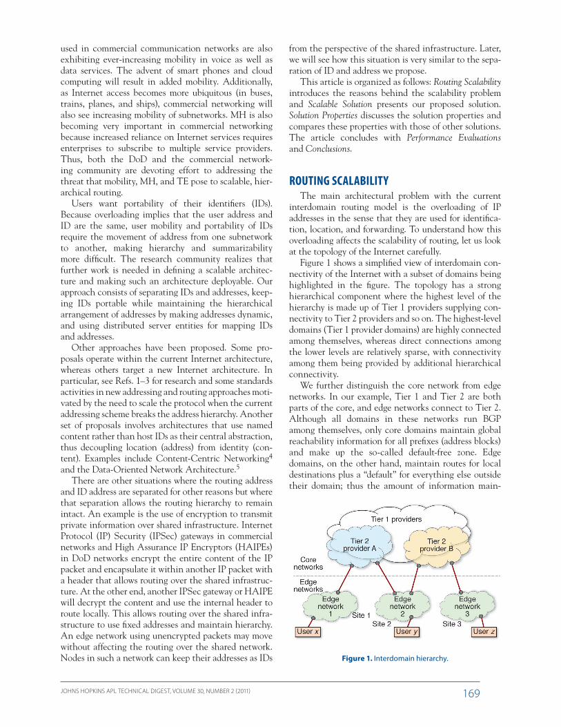
Figure 1 shows a simplified view of interdomain con-nectivity of the Internet with a subset of domains being highlighted in the figure. The topology has a strong hierarchical component where the highest level of the hierarchy is made up of Tier 1 providers supplying con-nectivity to Tier 2 providers and so on. The highest-level domains (Tier 1 provider domains) are highly connected among themselves, whereas direct connections among the lower levels are relatively sparse, with connectivity among them being provided by additional hierarchical connectivity.
We further distinguish the core network from edge networks. In our example, Tier 1 and Tier 2 are both parts of the core, and edge networks connect to Tier 2. Although all domains in these networks run BGP among themselves, only core domains maintain global reachability information for all prefixes (address blocks) and make up the so-called default-free zone. Edge domains, on the other hand, maintain routes for local destinations plus a “default” for everything else outside their domain; thus the amount of information main-
used in commercial communication networks are also exhibiting ever-increasing mobility in voice as well as data services. The advent of smart phones and cloud computing will result in added mobility. Additionally, as Internet access becomes more ubiquitous (in buses, trains, planes, and ships), commercial networking will also see increasing mobility of subnetworks. MH is also becoming very important in commercial networking because increased reliance on Internet services requires enterprises to subscribe to multiple service providers. Thus, both the DoD and the commercial network-ing community are devoting effort to addressing the threat that mobility, MH, and TE pose to scalable, hier-archical routing.
Users want portability of their identifiers (IDs). Because overloading implies that the user address and ID are the same, user mobility and portability of IDs require the movement of address from one subnetwork to another, making hierarchy and summarizability more difficult. The research community realizes that further work is needed in defining a scalable architec-ture and making such an architecture deployable. Our approach consists of separating IDs and addresses, keep-ing IDs portable while maintaining the hierarchical arrangement of addresses by making addresses dynamic, and using distributed server entities for mapping IDs and addresses.
Other approaches have been proposed. Some pro-posals operate within the current Internet architecture, whereas others target a new Internet architecture. In particular, see Refs. 1–3 for research and some standards activities in new addressing and routing approaches moti-vated by the need to scale the protocol when the current addressing scheme breaks the address hierarchy. Another set of proposals involves architectures that use named content rather than host IDs as their central abstraction, thus decoupling location (address) from identity (con-tent). Examples include Content-Centric Networking4 and the Data-Oriented Network Architecture.5
There are other situations where the routing address and ID address are separated for other reasons but where that separation allows the routing hierarchy to remain intact. An example is the use of encryption to transmit private information over shared infrastructure. Internet Protocol (IP) Security (IPSec) gateways in commercial networks and High Assurance IP Encryptors (HAIPEs) in DoD networks encrypt the entire content of the IP packet and encapsulate it within another IP packet with a header that allows routing over the shared infrastruc-ture. At the other end, another IPSec gateway or HAIPE will decrypt the content and use the internal header to route locally. This allows routing over the shared infra-structure to use fixed addresses and maintain hierarchy. An edge network using unencrypted packets may move without affecting the routing over the shared network. Nodes in such a network can keep their addresses as IDs Figure 1. Interdomain hierarchy.
L. BENMOHAMED, R. G. COLE, AND B. T. DOSHI
JOHNS HOPKINS APL TECHNICAL DIGEST, VOLUME 30, NUMBER 2 (2011)170
Multihoming MH refers to the case where a site is served by more
than one Internet service provider so that a multihomed site can connect to the Internet via more than one inter-domain link (such as Site 2 in Fig. 1). Edge networks multihome to increase the performance and reliability of their connectivity because MH provides backup paths, eliminates single points of failure, and allows achieving improved performance for the outbound traffic through load balancing.
Today MH is supported by injecting multiple, more specific address prefixes into the global routing table, which negatively impacts BGP’s scalability. Using the example in Fig. 1, assume Provider A makes a single aggregated prefix announcement, Pa, for all of its single-homed edge sites. If one of these edge sites decides to multihome, as is the case with Site 2 in this example, then the following takes place: Site 2, which is originally homed to Provider A, has an assigned prefix P2 included in Pa because it was originally assigned by Provider A (P2 is then a more specific—thus longer—prefix than Pa). Once Site 2 is homed to Provider B as well, Provider B will announce reachability to prefix P2 in addition to announcing its own aggregate Pb (P2 is aggregatable with Pa and not Pb). This will also force Provider A to announce P2 in addition to announcing the aggregate Pa; otherwise it will not attract any traffic going to Site 2. This is due to the longest-prefix-match rule used in IP forwarding, resulting in the de-aggregation of the BGP routing announcements of Provider A.
The demand for MH is increasing because of the increased reliance on the Internet for mission- and business-critical applications. This fact places a higher burden on the core routing system in two ways. First, as explained above, the individual prefixes for end sites, which used to be announced as part of their provider’s aggregate announcement, must now be propagated with-out aggregation into the routing system when they multi-home. Second, because a multihomed site connects at more than one location, if the status changes on any of the links connecting the site to its providers (link up or down), the change will be propagated into the core rout-ing system. This is in contrast to a single-homed site that follows the numbering scheme of its provider’s aggregate prefix, where no additional burden is put on core routing because the status of its connectivity to its provider is kept internal to the provider. These two developments (increase in the number of prefixes that need to be han-dled by core routing and in the rate at which the state of these prefixes changes) result in major scalability issues for the core interdomain routing.
Traffic Engineering TE is the ability to direct traffic along paths other
than those that would be computed by normal routing
tained is much smaller compared with that maintained by the routers in the core domains. The latter routers maintain complete information about all reachable des-tinations; they maintain full routing tables to reach all prefixes injected into BGP, which currently number in the hundreds of thousands.
Note that although Fig. 1 shows a two-tier core, there are often other tiers as well, with Providers A and B being in the lowest core tier of the hierarchy. In addition to the hierarchy of the topology itself, there is a more pronounced hierarchy in the addressing arrangement. Each Tier 1 provider is assigned a large contiguous block of addresses from the overall address space (each block is represented by an address prefix). Each second-tier provider gets a smaller contiguous block (represented by a more specific address prefix) from the block of its upstream provider, and so on.
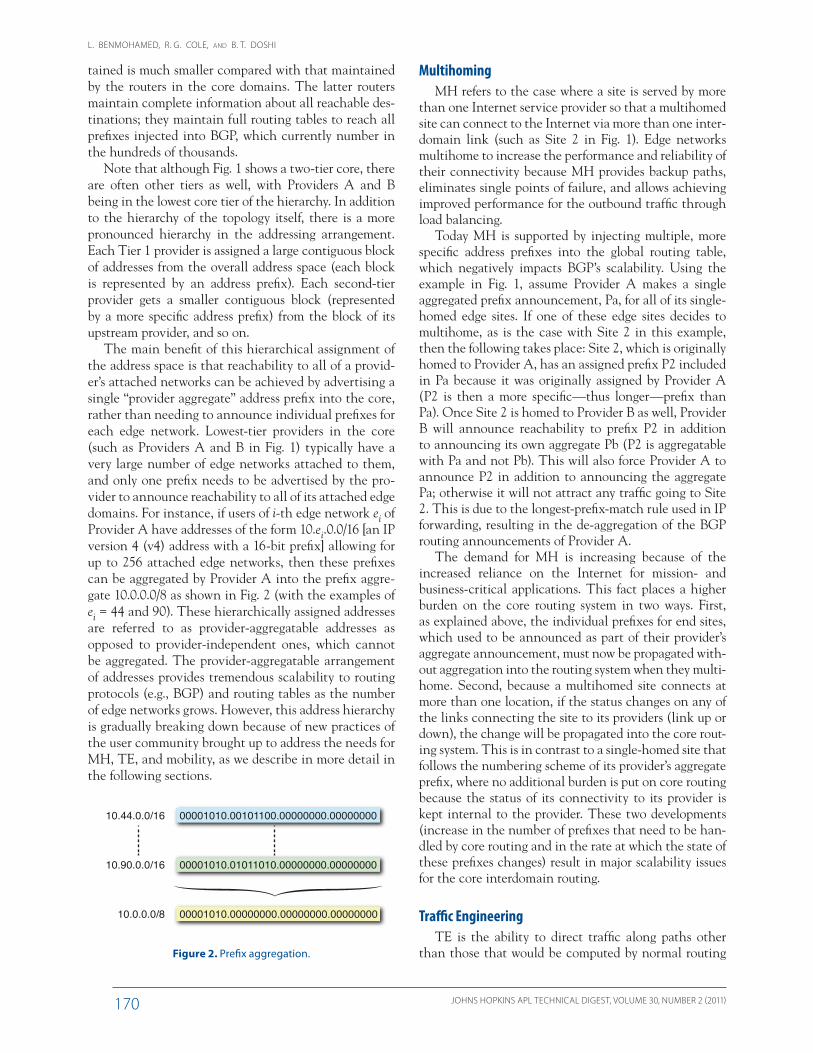
The main benefit of this hierarchical assignment of the address space is that reachability to all of a provid-er’s attached networks can be achieved by advertising a single “provider aggregate” address prefix into the core, rather than needing to announce individual prefixes for each edge network. Lowest-tier providers in the core (such as Providers A and B in Fig. 1) typically have a very large number of edge networks attached to them, and only one prefix needs to be advertised by the pro-vider to announce reachability to all of its attached edge domains. For instance, if users of i-th edge network ei of Provider A have addresses of the form 10.ei.0.0/16 [an IP version 4 (v4) address with a 16-bit prefix] allowing for up to 256 attached edge networks, then these prefixes can be aggregated by Provider A into the prefix aggre-gate 10.0.0.0/8 as shown in Fig. 2 (with the examples of ei = 44 and 90). These hierarchically assigned addresses are referred to as provider-aggregatable addresses as opposed to provider-independent ones, which cannot be aggregated. The provider-aggregatable arrangement of addresses provides tremendous scalability to routing protocols (e.g., BGP) and routing tables as the number of edge networks grows. However, this address hierarchy is gradually breaking down because of new practices of the user community brought up to address the needs for MH, TE, and mobility, as we describe in more detail in the following sections.
00001010.00101100.00000000.00000000
00001010.01011010.00000000.00000000
00001010.00000000.00000000.00000000
10.44.0.0/16
10.90.0.0/16
10.0.0.0/8
Figure 2. Prefix aggregation.
NAMING AND ADDRESSING FOR ROUTING SCALABILITY
JOHNS HOPKINS APL TECHNICAL DIGEST, VOLUME 30, NUMBER 2 (2011) 171
result in a larger number of prefixes being injected into interdomain routing. A corresponding higher prefix update rate takes place as well because of three factors: (i) the increase in prefixes (when an interdomain link goes down or comes back up many prefixes are affected at the same time instead of just one), (ii) the TE dynamic advertisement of prefixes, and (iii) the mobility of hosts/nodes/subnets. This implies that a higher load is placed on the core routing system in terms of memory resources to store a larger number of advertised prefixes and their associated state information, node processing resources to compute routes to each advertised prefix, and net-work bandwidth resources to support state exchanges for a larger number of prefixes with a higher update rate. This creates a major challenge for the scalability of inter domain routing protocols. To maintain scal-able routing while supporting MH/TE and mobility, the interdomain routing in the core needs to undergo funda-mental changes. As we describe in the following section, the changes recommended in our solution are achieved through the introduction of a clear separation between an address and an ID as well as the implementation of an efficient address-to-ID mapping system, with the address being a descriptor of a physical point of attachment and the ID being a permanent name.
SCALABLE SOLUTIONAs explained previously, the lack of scalable support
to MH/TE and mobility is a problem associated with having IP addresses play multiple roles. An IP address is drawn from a global address space and was meant to serve one purpose. It is now used for multiple purposes. It is used to identify hosts and network node interfaces (end point ID) and is also used to define the location of the node (as part of a network by specifying point of attachment to the network). Although hosts want the IDs to be permanent, having the same entity play the two roles implies that the IP address, and hence the locator, remains permanent. This results in the de-aggregation mentioned above. The solution is to sepa-rate the IDs from addresses (locators), let IDs be (semi) permanent, and let addresses be dynamic and hierarchi-cal. Thus, we require that IDs be distinct from addresses. Addresses are used for locating and routing and may change when the object moves so that the hierarchy can be maintained. Identifiers are used as semiperma-nent names for objects and remain associated with the objects as they move from network to network. Because the source of a packet may only know the ID of the destination, it needs to map the ID to an address so it can insert the address into the packet for routing pur-poses. In the following sections we present the different components of our Address-Identifier Mapping System (AIMS) solution.6
through an intradomain protocol (Interior Gateway Protocol) and an interdomain protocol (Exterior Gate-way Protocol). TE is performed by both core and edge domains to arrange for certain traffic to use or avoid certain network paths, often to place traffic where some path attributes are more favorable to the traffic being placed on these paths, and also to balance the load among different paths. The ability to control the path taken by inbound traffic (traffic entering the domain) is as important as the ability to control the outbound path for traffic exiting the domain. However, outbound TE can be simply achieved using local routing. Indeed, adjustment of Interior Gateway Protocol metrics con-trols how much traffic flows over different internal paths to specific exit points. Because outbound TE is achieved via a site’s own Interior Gateway Protocol, it does not impact the interdomain routing (note that in this arti-cle, unless specified otherwise, TE refers to the current practice of inbound interdomain TE).
On the other hand, inbound TE (the desire to have particular prefixes in a domain reached via particular edge routers) is achieved by taking one prefix, dividing it into a number of smaller and more specific ones, and then advertising them to gain finer-grained control over the paths used to carry traffic covered by those prefixes. This TE practice by network operators results in the de-aggregation of a single address block (represented by one address prefix) into smaller ones whose correspond-ing prefixes are injected into the interdomain routing. Moreover, beyond this resulting increase in the number of prefixes being advertised in core routing, another common practice is the dynamic advertisement of these smaller prefixes to achieve additional dynamic control over directing inbound traffic (such as by time of day). This increases the frequency of routing updates. As a result, similar to MH, there is a compounded effect on core routing services: additional prefixes must be carried in the routing system and these prefixes drive higher update rates.
Mobility A network that supports mobility provides the capa-
bility for a host or subnet to change its topological con-nectivity (its point of attachment) while continuing to be connected (able to send/receive data packets). If a mobile entity keeps its address when it moves from network to network and announces its prefix from its new attachment point to remain reachable, it breaks the address hierarchy and summarizability, which results in more prefixes being injected into core routing. Moreover, the additional prefixes being injected will be dynamic because of mobility, thus resulting in dynamic updates to the core routing system.
In summary, mobility and the practices of MH and TE all induce de-aggregation of address prefixes and

L. BENMOHAMED, R. G. COLE, AND B. T. DOSHI
JOHNS HOPKINS APL TECHNICAL DIGEST, VOLUME 30, NUMBER 2 (2011)172
Each backbone-level server (BLS) is responsible for stor-ing mappings and answering queries for an assigned set of IDs. The partitioning is done so that BLSs together have mappings for all IDs and so that each ID is in more than one BLS (for redundancy). Each BLS knows the arrange-ment of the ID assignments so it knows which BLSs can answer which queries. In addition to being responsible for a set of IDs from the global ID space, each BLS is also assigned a block of addresses from the global address space that are “homed” to it. These addresses represent the address space of the BLS, and it is responsible for updating appropriate BLSs when an object moves into its address space or an ID leaves its address space. The update information may come from the next lower-level mapping server [tree-level server (TLS) described below] or directly from the server [authentication and address assignment server (AAS) described below] that provides addresses to objects (IDs) as they move in and de-allo-cates those addresses as the IDs move out. When a BLS receives an update (addition or removal of an ID for an address in its territory), it identifies the BLSs responsible for that ID and sends update messages to those BLSs. In addition, it may cache the mapping in its own map-ping table. This BLS is also responsible for field queries coming from any address (attachment point) in its ter-ritory. When a query arrives at that BLS along with the ID to be mapped, the BLS knows which BLSs (including itself) have the mapping so it picks one (in some load-balancing way) and sends the query there. If that fails, it can query the next on the list and so on. When it receives the address value, it forwards the mapping to the requester via lower-level servers. Of course, querying other BLSs is not needed if the BLS receiving the query from lower-level servers has the mapping. Note that for a closed network, BLSs can be considered enterprise-level servers and are likely to be located in the fixed networks, whereas for public Internet these are global backbone servers typically associated with Tier 1 providers.
In addition to their mapping function described above, the BLSs store information about the objects
Hierarchical AddressingTo maintain scalable routing, we make the address
assignment follow the topological hierarchy where each domain obtains a block of addresses from the domain in the higher tier it attaches to (large blocks of the address space are first given to Tier 1 providers), with the address field typically divided into segments so each segment represents the address at a given level of the hierarchy. To achieve this in our proposed solution, each level of the hierarchy has trusted servers and address blocks to assign to lower levels so the address hierarchies are maintained even in presence of a high degree of mobil-ity. As the point of attachment of an object changes, the object’s address needs to change to reflect its new place in the hierarchy. Note that an object may be a user, a host, a network node, a subnet, or a network domain.
It is important to note that we allow objects to have multiple addresses if they are attached to more than one higher-level domain (such as during MH). Instead of the multihomed object injecting its addresses through its higher-level domains as currently practiced, it acquires hierarchical addresses from each one of them. Thus, the addresses remain hierarchical and allow scalable rout-ing. This fact, along with the way the multiple addresses are used, will be further explained below.
Distributed Mapping InfrastructureBecause addresses are dynamic whereas IDs are rela-
tively static or even permanent, we need to be able to map the ID of an object to its current address so the object can be reached using scalable routing. We propose a set of server types and a corresponding arrangement to implement this mapping function. As mentioned earlier, the problem and solution are related to our work on the problem of managing peer discovery in secure Virtual Private Networks (VPNs) using IPSec and HAIPE.7 The problem is also related to managing mobility in cellu-lar networks and to managing name-to-address map-ping provided by the Domain Name System (DNS). (The system closest to a mapping system in the Internet today is the DNS. Obviously it can be extended for use in storing the address-to-ID mapping. In this case, the benefit of a DNS-based mapping system would be the operational experience in operating and testing such a system and thus could provide a foundation on which a mapping service can be built.) Figure 3 shows the serv-ers proposed in our solution, and the relationship among them is described in more detail below.
Backbone-Level ServerThese servers, usually located in the highest tier of
the fixed backbone, are designed to collectively store and provide the ID-to-address mapping for all IDs. Each server provides the two functions of storing and updating the mapping as well as answering any mapping queries.
Figure 3. Distributed mapping infrastructure.

NAMING AND ADDRESSING FOR ROUTING SCALABILITY
JOHNS HOPKINS APL TECHNICAL DIGEST, VOLUME 30, NUMBER 2 (2011) 173
who have the permission to reach the object. This task is facilitated by the AAS. AASs can get information on an object moving out or joining a domain via the local routing protocol or other means. An AAS associ-ated with the domain from which the object moves out will send a message of removal to the local TLS, which updates its table and propagates the message to higher levels and ultimately to the appropriate BLSs. Similarly, the AAS in the domain to which an object attaches will send a message to the BLS to authenticate the ID and then allocates a new address. The new ID–address rela-tionship is propagated up, and all servers are updated.
As mentioned above, we can provide additional controls during the authentication process. Associated with an ID are other parameters such as the ID authen-tication parameters, highest allowable precedence level, maximum bandwidth available to the ID, both the quality of service and quality of protection available to the ID, etc. These parameters are selected by poli-cies established at the “home network” when the object first appears and are then propagated up the chain to the BLSs. During the authentication, the BLS will also send these parameters back to the AAS. These param-eters, along with local policies, can now be used by the AAS to select precedence, quality of service, and quality of protection levels permissible to this ID. The informa-tion is propagated to entities in charge of access control in the domain. In addition to these controls at object authentication time, additional dynamic controls used during mapping query time are presented below.
SOLUTION PROPERTIES In this section we present an analysis of the proper-
ties of our solution and discuss other proposed solutions to deal with scalable routing for MH/TE and mobility. As we will show below, our AIMS solution addresses MH/TE and mobility simultaneously, whereas others have tailored solutions to either MH/TE or mobility but not both.
MH/TE SolutionsLocator/ID Separation Protocol (LISP) is the main
protocol in this class being discussed by the Internet Research Task Force (IRTF).2 To make it easy for net-works to change provider, to multihome, or to exercise TE, LISP decouples the edge network addresses from those in the core. It creates separate name spaces, one for the core and one for edge sites: the end system ID (EID) is the new name space routable in the edge sites attached to the core and is the one that goes in DNS records, and the routing locator is the existing name space routable in the core and used to address core and core-attached routers (both name spaces can be either IPv4 or IPv6). Blocks of contiguous IDs are allocated to edge networks
associated with IDs. The authentication and crypto-graphic parameters for that ID, levels of services autho-rized to the user (if the object is a user), and even the aging parameters for the mapping are few examples of such stored information. We will describe below some of this stored information and its usage.
Tree-Level ServerBecause network domains are arranged in hierarchies
and addresses are arranged in matching hierarchies, we have TLSs associated with each level. Each TLS is responsible for the addresses in the portion of the tree rooted at the level the server is in. In that sense a BLS also functions as the highest-level TLS. Whereas the BLSs use ID-based partitioning, lower levels (TLSs) are partitioned based only on addresses. As objects move in and out of domains, the servers (AAS described below) assigning new addresses to IDs send update messages to the TLS in that domain. The TLS caches the ID to address mapping and sends an update to the higher-level TLS in the tree. Ultimately, the update is received by the highest-level TLS (BLS) and is sent to all BLSs responsible for that ID.
When an object needs a mapping from ID to address, it sends a query to its local TLS. If that TLS has the mapping (in the cache if the address is in the portion of tree rooted at this TLS), it will respond with the address. If not, the query is sent up to the next TLS level and so on. Because the set of BLSs always has the mapping, the response will arrive back to the requester. The local TLS (and requesting object) can store the mapping in a local cache with a timeout T after which the cache entry is discarded. Note that the levels of the hierarchy do not each need a TLS because higher-level servers up to BLS are always available to propagate updates and answer queries. Lower-level servers are used mainly to reduce the load on higher-level servers, especially when there are communities of interest. In this case a TLS serving a community of interest would answer a large fraction of queries, thus reducing the query load on the BLSs. They also help in highly mobile edge networks where band-width limitation in reachback links to the backbone makes it highly desirable to keep as many queries local as possible. For edge networks based on specific mobile ad hoc network technology, a tailored mobility solution within the mobile ad hoc network can be devised as in Ref. 8.
Authentication and Address Assignment Server When an object moves and changes its attachment
point to the rest of the network infrastructure, we need to update the address (if the hierarchy requires that) and propagate the new ID–address mapping to TLSs and BLSs so that the object remains accessible to all

L. BENMOHAMED, R. G. COLE, AND B. T. DOSHI
JOHNS HOPKINS APL TECHNICAL DIGEST, VOLUME 30, NUMBER 2 (2011)174
tity Protocol12 is based on IPv6 and defines a rendezvous server functionality similar to that of the IPv6 home agent. MIP is not widely deployed; there is hardly any deployment of MIPv6 and only partial deployment of MIPv4. This is partly because of the performance hit of the tunnelling process and the amount of state manage-ment overhead at the routers implementing the home agent functionality. These mobility solutions do not deal with the routing system—they use an overlay solution on top of existing IP routing. Consequently, they do not deal with any routing scalability issues.
We now summarize the properties of our solution and how it compares with the above solutions.
Routing Scalability The number of individual prefixes that are advertised
in the global routing system continues to increase, with each individual prefix requiring processing resources. As a lower bound, each autonomous system needs only a single aggregate route; however, as of December 2010, there are close to 36,000 autonomous systems announc-ing routes for a total of 340,000 prefixes.13 The overall routing update rate is increasing as well, requiring rout-ers to process updates at an increased rate (resulting in slower convergence if they cannot keep up). This rate is dependent on the number of individual prefixes, which is increasing, and the mean update rate of a prefix, which is also increasing because of some of the TE practices. With the ID–address separation of the AIMS architec-ture, the number of prefixes can be kept small because they can be more aggressively aggregated, and the prefix update rate is cut significantly partly because of the fact that mobility is being handled by the mapping system rather than by global routing update. This improves the scalability of the routing system by making the core routing tables smaller and more stable.
Multihoming and Traffic EngineeringUnder the AIMS architecture, MH and TE become
transparent to the core routing system, thus increas-ing routing scalability compared with today’s practice, which requires updates to the core routing. In order to implement TE, if we require a host to be reached via a particular edge link (the one that best meets the TE objective), we map its ID to an address from the address block obtained from the provider at that attachment link (hosts can have multiple addresses when their edge network has multiple attachment points). Note that we have the additional benefit that TE can be accomplished per flow. This provides TE control that is more granu-lar than that of today’s TE updates—today’s TE updates affect complete prefixes, which typically account for a substantial fraction of an edge network’s traffic. More-over, TE changes can also be made faster because they
(EID prefixes), and each network assigns IDs to its hosts in the block that it received. LISP requires network support only (no host involvement) where edge routers connecting sites to the core are aware of the separa-tion but hosts are not. Edge routers perform encapsula-tion/de-capsulation in a tunnel mode operation where EIDs are in the inner headers and locators are in the outer headers of packets. An edge router at a source site (ingress tunnel router) is responsible for finding remote EID-to-remote routing locator mapping and encapsulat-ing to locators at the destination site. The edge router at the destination site (egress tunnel router) performs de-capsulation as shown in Fig. 4. LISP cannot deal with mobility: LISP provides hosts with IDs that are provider independent but still topologically significant (locally within an edge network). In order to support mobil-ity, the ID needs to be stable so as to identify the host independently of its topological location. Whereas in AIMS we use a true locator–identity separation, LISP’s locator–ID separation is in fact a locator–locator separa-tion that involves separating the addressing regions into core and edge. Moreover, the mapping system is based on aggregated EID prefixes whereas host mobility would require mapping for individual IDs. In order to support mobility, LISP would need yet another mapping from a true host ID to an EID.
Mobility SolutionsCurrent solutions for mobility include Mobile IP
(MIPv49 and MIPv610) and Network Mobility,11 which handles group mobility in a way similar to MIP. These solutions require that a home agent function be deployed at some routers in order to keep track of the mobile entity’s current location. They use renumbering and cre-ation of a tunnel from the moving object’s new topologi-cal location back to its original location. Tunnelling is used to forward data packets via care-of addresses. Data are directed to a home agent that is updated with the current location of the mobile entity. The Host Iden-
Figure 4. Locator/ID Separation Protocol. D, destination; S, source.
NAMING AND ADDRESSING FOR ROUTING SCALABILITY
JOHNS HOPKINS APL TECHNICAL DIGEST, VOLUME 30, NUMBER 2 (2011) 175
tion networks. This particular OC-12 link terminates on a router in Florida and aggregates traffic from research and education networks of four regions in the overall coverage area of the AmericasPATH network.
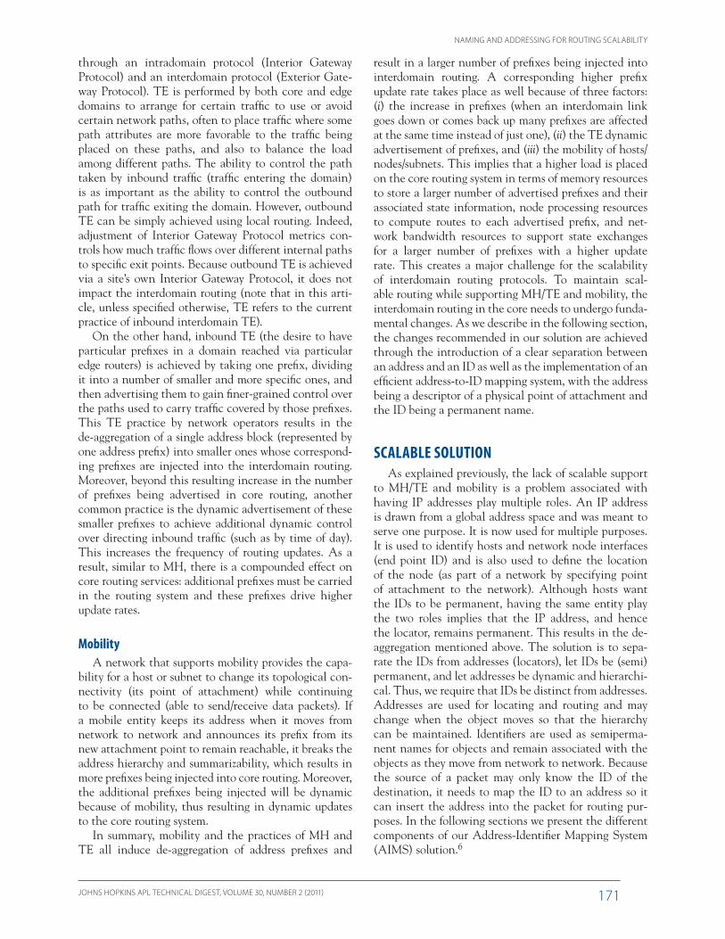
In our proposed solution, the lower-level TLS serv-ers are used mainly to reduce the load on higher-level servers through caching. In this study we focus on the dynamics of the cache at edge networks temporarily storing address–ID mappings. In the context of the data set described above, this would correspond to the TLS associated with the edge network regions feeding the AmericasPATH link. We examine various parameters of the cache itself as well as the lookup traffic volume. At the end of this section, we discuss the performance of the BLS layer as well.
Figure 5 shows a model of the address-ID mapping solution with a number of traffic sources (Source 1 to Source n) and a lower-level TLS. Queries result in either a cache hit (case a) or a cache miss. A cache miss results in the generation of a query to higher-level servers in the hierarchy (case b), and arriving query responses are cached for potential reuse (case c). A cache timeout parameter T controls the cache entry expiration (case d). We experimented with two models for cache entry time-out: (i) hard timeout where an entry expires T seconds after entering the cache, and (ii) soft timeout where an entry expires when it has not been used for T seconds. In this case it gets refreshed for an additional T whenever it is re-used within T, whereas in the first case it is purged from the cache exactly after T seconds regardless of the level of activity (hit rate) of the cache entry.
We first start with examining the data set itself, which represents two days’ worth of packet trace capture. The file format of the trace (16 GB total) is standard packet capture (pcap) and contains packet headers only for privacy reasons (the address information has been ano-nymized with the source/destination IP addresses modi-fied through a one-to-one mapping that preserves the
involve an update to our distributed mapping infrastruc-ture as opposed to a global routing update that usually takes on the order of minutes to converge.
For resilient routing, we can map an ID to several of its addresses, with the mapping query returning an ordered list of addresses that gives the sender alternate reachability addresses in case an edge link fails. More-over, the mapping can be made dynamic in order to achieve dynamic TE where the decision regarding which edge link to use for a particular flow is made at mapping query time. In this case, because the mapping would need to be updated quickly and in order to avoid creating additional signalling and processing overhead, we pro-pose the following dynamic version of AIMS (AIMS-D): When the TLS associated with an edge network sends mapping updates regarding IDs in its territory to higher-level TLSs up to the BLSs, it can tag a mapping as being dynamic, in which case when a query for that ID is received, the dynamic tag would require the query to be forwarded to the lowest-level TLS that advertised the ID. This TLS can then reply with the appropriate mapping depending on current traffic conditions in the edge net-work. Moreover, because different paths between multi-homed networks do not have the same quality, AIMS-D can be further enhanced to use best-quality end-to-end paths. Further investigation into this would be needed because improving routing quality by providing better -performing paths would require that interdomain rout-ing (BGP) find these best-quality paths. Enhancements to BGP (as described in Ref. 14) would allow it to make such quality-of-service routing decisions.
MobilityAIMS handles mobility through an update to the
mapping system that guarantees that the mobile entity will always be reachable whenever a source needs to establish a new session with it. To allow for in-session mobility where an existing transport session needs to be maintained after a move takes place, some tunnelling of packets may be needed to avoid packet drops while the mapping is being updated.
PERFORMANCE EVALUATIONSThe benefits of our solution compared with today’s
Internet practice has been demonstrated qualitatively in the section above. In this section we quantify some of the associated metrics. We developed a model to evalu-ate the performance of the address–ID mapping system and generated performance results using a data set rep-resenting a traffic trace from a deployed network. The data were collected on an OC-12 link (622 Mbps) in the AmericasPATH network. This network interconnects the research and education networks in South and Cen-tral America to U.S. and non-U.S. research and educa-
Cache at TLS
To higher-levelTLS and BLS
a
c b
d
a
c
bSource 1
Source n
d
...........
Figure 5. TLS model.
L. BENMOHAMED, R. G. COLE, AND B. T. DOSHI
JOHNS HOPKINS APL TECHNICAL DIGEST, VOLUME 30, NUMBER 2 (2011)176
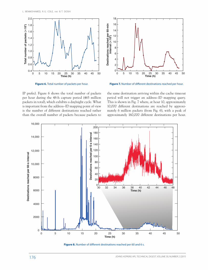
the same destination arriving within the cache timeout period will not trigger an address–ID mapping query. This is shown in Fig. 7 where, at hour 10, approximately 10,000 different destinations are reached by approxi-mately 6 million packets (from Fig. 6), with a peak of approximately 160,000 different destinations per hour.
IP prefix). Figure 6 shows the total number of packets per hour during the 48-h capture period (465 million packets in total), which exhibits a day/night cycle. What is important from the address–ID mapping point of view is the number of different destinations reached rather than the overall number of packets because packets to
2.0
Tota
l num
ber o
f pac
kets
(�10
7 ) 1.8
1.6
1.4
1.2
1.0
0.8
0.6
0.40 5 10 15 20 25
Time (h)30 35 40 45 50
Figure 6. Total number of packets per hour.
Des
tinat
ions
reac
hed
per 6
0-m
inin
terv
al (�
104 )
18
16
14
12
10
8
6
4
2
00 5 10 15 20 25
Time (h)30 35 40 45 50
Figure 7. Number of different destinations reached per hour.
16,000
14,000
12,000
10,000
Des
tinat
ions
reac
hed
per 6
0-s
inte
rval
Des
tinat
ions
reac
hed
per 6
-s in
terv
al
8000
6000
4000
2000
200
180
160
140
120
100
80
60
40
20
0
00 5 10 15 20 25
Time (h)
Time (h)
30
30 32 34 36 38 40 42 44 46 48
35 40 45 50
Figure 8. Number of different destinations reached per 60 and 6 s.
NAMING AND ADDRESSING FOR ROUTING SCALABILITY
JOHNS HOPKINS APL TECHNICAL DIGEST, VOLUME 30, NUMBER 2 (2011) 177
Figure 8 shows the same data at smaller timescales where a spiky behavior is exhibited. The data are shown at a timescale of 60 s and at a zoomed-in timescale of 6 s. The figure shows that the number of different destinations reached per minute can be as high as almost 16,000, and we would expect the cache size to be at least as big when the cache timeout value is T = 60 s.
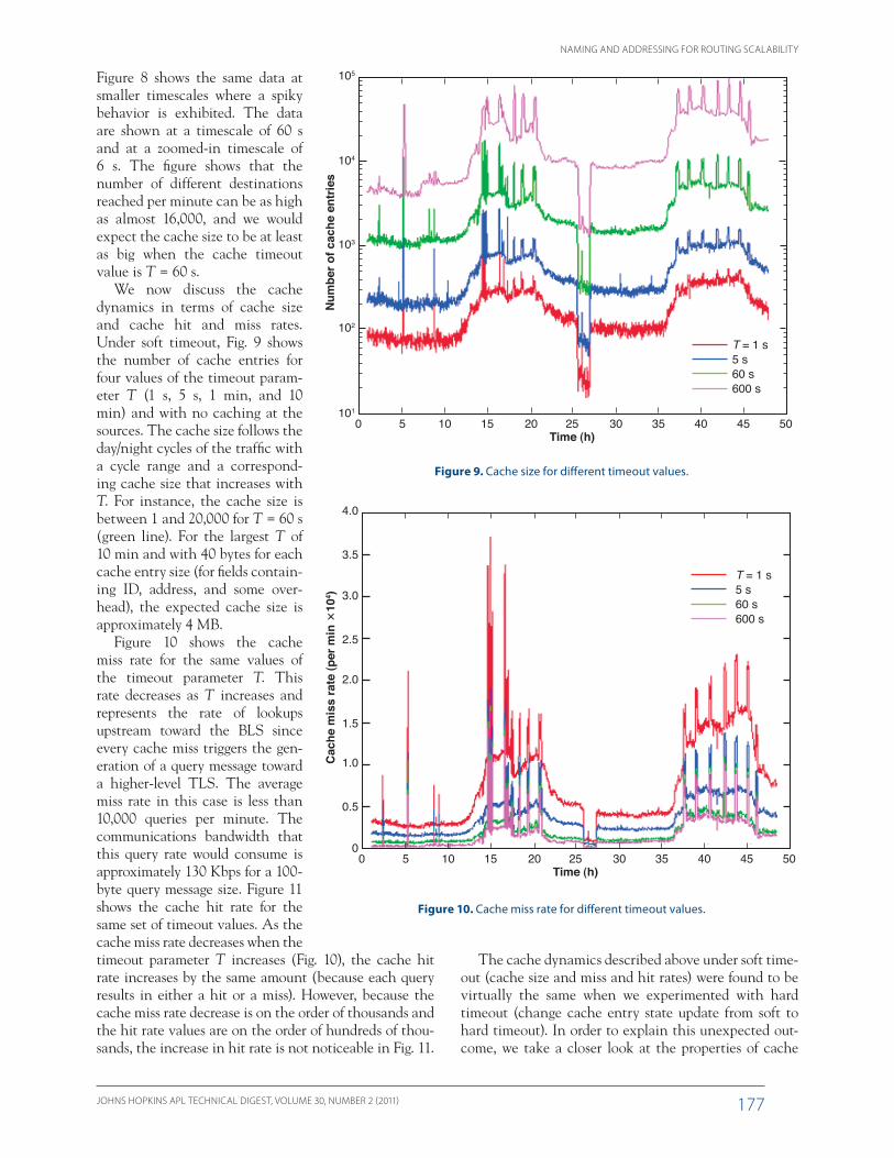
We now discuss the cache dynamics in terms of cache size and cache hit and miss rates. Under soft timeout, Fig. 9 shows the number of cache entries for four values of the timeout param-eter T (1 s, 5 s, 1 min, and 10 min) and with no caching at the sources. The cache size follows the day/night cycles of the traffic with a cycle range and a correspond-ing cache size that increases with T. For instance, the cache size is between 1 and 20,000 for T = 60 s (green line). For the largest T of 10 min and with 40 bytes for each cache entry size (for fields contain-ing ID, address, and some over-head), the expected cache size is approximately 4 MB.
Figure 10 shows the cache miss rate for the same values of the timeout parameter T. This rate decreases as T increases and represents the rate of lookups upstream toward the BLS since every cache miss triggers the gen-eration of a query message toward a higher-level TLS. The average miss rate in this case is less than 10,000 queries per minute. The communications bandwidth that this query rate would consume is approximately 130 Kbps for a 100-byte query message size. Figure 11 shows the cache hit rate for the same set of timeout values. As the cache miss rate decreases when the timeout parameter T increases (Fig. 10), the cache hit rate increases by the same amount (because each query results in either a hit or a miss). However, because the cache miss rate decrease is on the order of thousands and the hit rate values are on the order of hundreds of thou-sands, the increase in hit rate is not noticeable in Fig. 11.
The cache dynamics described above under soft time-out (cache size and miss and hit rates) were found to be virtually the same when we experimented with hard timeout (change cache entry state update from soft to hard timeout). In order to explain this unexpected out-come, we take a closer look at the properties of cache
4.0
3.0
Cac
he m
iss
rate
(per
min
�10
4 )
1.0
00 5 10 15 20 25
Time (h)30 35
T = 1 s5 s60 s600 s
40 45 50
2.0
3.5
2.5
0.5
1.5
Figure 10. Cache miss rate for different timeout values.
105
104
Num
ber o
f cac
he e
ntrie
s102
101
0 5 10 15 20 25Time (h)
30 35
T = 1 s5 s60 s600 s
40 45 50
103
Figure 9. Cache size for different timeout values.

L. BENMOHAMED, R. G. COLE, AND B. T. DOSHI
JOHNS HOPKINS APL TECHNICAL DIGEST, VOLUME 30, NUMBER 2 (2011)178
a longer time does not correlate with having a larger hit rate.
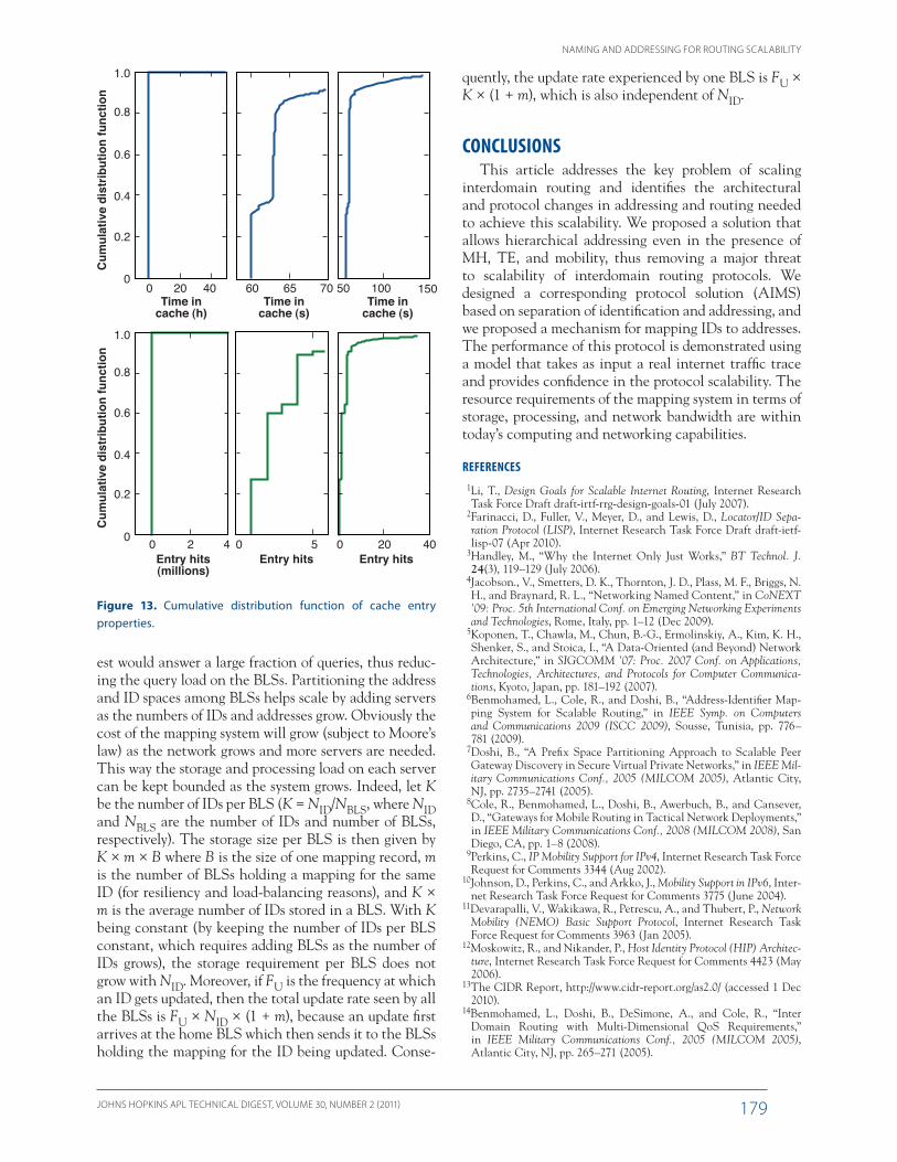
When plotting the cumulative distribution function for the time spent in the cache and the number of hits per cache entry as shown in Fig. 13, we see that 90% of entries remain less than 70 s in the cache (under soft timeout with T = 60 s, this means that these entries were used for 10 s) and 99% remained less than 150 s. Moreover, 90% of entries were used to forward less than 6 packets and 99% were used to forward less than 40 packets. Note that in this figure, because of the wide range of values on the x axis, zoomed-in versions are plot-ted to capture the details of the dynamics along the y axis. In sum-mary, the fact that hard timeout does not result in any significant change in the cache dynamics is due to the nature of the traffic in that most destinations are con-
tacted for a short period of time and with few packets exchanged, and only few destinations are active for a long time or exchange a large number of packets.
In addition to the above simulation results for the TLS layer, we briefly discuss the performance of the BLS layer. In our distributed mapping infrastructure, the lower-level servers (TLSs) are used mainly to reduce the load on higher-level servers (BLSs) through cach-ing, especially when there are communities of interests so a large fraction of queries can be answered at lower levels. In this case a TLS serving a community of inter-
entries. As cache entries time out, we record the time the entry spent in the cache and the number of pack-ets that were forwarded based on this entry. We do this for T = 60 seconds under soft timeout, but the same qualitative results hold true for other parameter values. Figure 12 shows the time each entry spends in cache and the corresponding number of hits. We observe that most cache entries remain in the cache for a short time with only some remaining for a long time; most entries for-ward a small number of packets and only a few of them forward a large number; and remaining in the cache for
4.0
4.5
3.0
Cac
he m
iss
rate
(per
min
�10
5 )
1.0
00 5 10 15 20 25
Time (h)30 35
T = 1 s5 s60 s600 s
40 45 50
2.0
3.5
2.5
0.5
1.5
Figure 11. Cache hit rate for different timeout values.
76543Cache entry index
210
60
40
Tim
e in
cac
he (h
)N
umbe
r of h
its (�
107 )
20
0
4.03.02.01.0 3.52.51.50.50Number of hits (�107)
50
40
30
Tim
e in
cac
he (h
)
20
10
0
3
4
2
1
0
Figure 12. Properties of cache entries.
NAMING AND ADDRESSING FOR ROUTING SCALABILITY
JOHNS HOPKINS APL TECHNICAL DIGEST, VOLUME 30, NUMBER 2 (2011) 179
quently, the update rate experienced by one BLS is FU × K × (1 + m), which is also independent of NID.
CONCLUSIONSThis article addresses the key problem of scaling
interdomain routing and identifies the architectural and protocol changes in addressing and routing needed to achieve this scalability. We proposed a solution that allows hierarchical addressing even in the presence of MH, TE, and mobility, thus removing a major threat to scalability of interdomain routing protocols. We designed a corresponding protocol solution (AIMS) based on separation of identification and addressing, and we proposed a mechanism for mapping IDs to addresses. The performance of this protocol is demonstrated using a model that takes as input a real internet traffic trace and provides confidence in the protocol scalability. The resource requirements of the mapping system in terms of storage, processing, and network bandwidth are within today’s computing and networking capabilities.
REFERENCES 1Li, T., Design Goals for Scalable Internet Routing, Internet Research
Task Force Draft draft-irtf-rrg-design-goals-01 (July 2007). 2Farinacci, D., Fuller, V., Meyer, D., and Lewis, D., Locator/ID Sepa-
ration Protocol (LISP), Internet Research Task Force Draft draft-ietf-lisp-07 (Apr 2010).
3Handley, M., “Why the Internet Only Just Works,” BT Technol. J. 24(3), 119–129 (July 2006).
4Jacobson., V., Smetters, D. K., Thornton, J. D., Plass, M. F., Briggs, N. H., and Braynard, R. L., “Networking Named Content,” in CoNEXT ’09: Proc. 5th International Conf. on Emerging Networking Experiments and Technologies, Rome, Italy, pp. 1–12 (Dec 2009).
5Koponen, T., Chawla, M., Chun, B.-G., Ermolinskiy, A., Kim, K. H., Shenker, S., and Stoica, I., “A Data-Oriented (and Beyond) Network Architecture,” in SIGCOMM ’07: Proc. 2007 Conf. on Applications, Technologies, Architectures, and Protocols for Computer Communica-tions, Kyoto, Japan, pp. 181–192 (2007).
6Benmohamed, L., Cole, R., and Doshi, B., “Address-Identifier Map-ping System for Scalable Routing,” in IEEE Symp. on Computers and Communications 2009 (ISCC 2009), Sousse, Tunisia, pp. 776–781 (2009).
7Doshi, B., “A Prefix Space Partitioning Approach to Scalable Peer Gateway Discovery in Secure Virtual Private Networks,” in IEEE Mil-itary Communications Conf., 2005 (MILCOM 2005), Atlantic City, NJ, pp. 2735–2741 (2005).
8Cole, R., Benmohamed, L., Doshi, B., Awerbuch, B., and Cansever, D., “Gateways for Mobile Routing in Tactical Network Deployments,” in IEEE Military Communications Conf., 2008 (MILCOM 2008), San Diego, CA, pp. 1–8 (2008).
9Perkins, C., IP Mobility Support for IPv4, Internet Research Task Force Request for Comments 3344 (Aug 2002).
10Johnson, D., Perkins, C., and Arkko, J., Mobility Support in IPv6, Inter-net Research Task Force Request for Comments 3775 (June 2004).
11Devarapalli, V., Wakikawa, R., Petrescu, A., and Thubert, P., Network Mobility (NEMO) Basic Support Protocol, Internet Research Task Force Request for Comments 3963 (Jan 2005).
12Moskowitz, R., and Nikander, P., Host Identity Protocol (HIP) Architec-ture, Internet Research Task Force Request for Comments 4423 (May 2006).
13The CIDR Report, http://www.cidr-report.org/as2.0/ (accessed 1 Dec 2010).
14Benmohamed, L., Doshi, B., DeSimone, A., and Cole, R., “Inter Domain Routing with Multi-Dimensional QoS Requirements,” in IEEE Military Communications Conf., 2005 (MILCOM 2005), Atlantic City, NJ, pp. 265–271 (2005).
est would answer a large fraction of queries, thus reduc-ing the query load on the BLSs. Partitioning the address and ID spaces among BLSs helps scale by adding servers as the numbers of IDs and addresses grow. Obviously the cost of the mapping system will grow (subject to Moore’s law) as the network grows and more servers are needed. This way the storage and processing load on each server can be kept bounded as the system grows. Indeed, let K be the number of IDs per BLS (K = NID/NBLS, where NID and NBLS are the number of IDs and number of BLSs, respectively). The storage size per BLS is then given by K × m × B where B is the size of one mapping record, m is the number of BLSs holding a mapping for the same ID (for resiliency and load-balancing reasons), and K × m is the average number of IDs stored in a BLS. With K being constant (by keeping the number of IDs per BLS constant, which requires adding BLSs as the number of IDs grows), the storage requirement per BLS does not grow with NID. Moreover, if FU is the frequency at which an ID gets updated, then the total update rate seen by all the BLSs is FU × NID × (1 + m), because an update first arrives at the home BLS which then sends it to the BLSs holding the mapping for the ID being updated. Conse-
1.0
0.8
0.6
Cum
ulat
ive
dist
ribut
ion
func
tion
0.4
0.2
00 20
Time incache (h)
Time incache (s)
Time incache (s)
40 60 65 70 50 100 150
0 2Entry hits(millions)
Entry hits Entry hits4 0 5 0 20 40
1.0
0.8
0.6
Cum
ulat
ive
dist
ribut
ion
func
tion
0.4
0.2
0
Figure 13. Cumulative distribution function of cache entry properties.

L. BENMOHAMED, R. G. COLE, AND B. T. DOSHI
JOHNS HOPKINS APL TECHNICAL DIGEST, VOLUME 30, NUMBER 2 (2011)180
Lotfi Benmohamed is a member of APL’s Senior Professional Staff in the Milton S. Eisenhower Research Center. Since joining APL in 2003, he has been involved in control and routing in sensor networks and mobile ad hoc networks and in protocol design and analysis of IP networks. Robert G. Cole (not pictured) was a Senior Professional Staff member in the Milton Eisenhower Research Center until February 2010. He is now the Deputy Director of the Network Science Technology Research Center in the U.S. Army Communications-Electronics Research, Devel-
opment, and Engineering Center. His work focuses on the development of network science for Army applications. Bharat T. Doshi is the Director of the Milton S. Eisenhower Research Center, and he was previously the Director of Transformational Communication in APL’s Applied Information Science Department, where he led many sys-tems engineering working groups that contributed technical solutions to the development of the Global Information Grid vision. For further information on the work reported here, contact Dr. Lotfi Benmohamed. His e-mail address is [email protected].
The Authors
Bharat T. DoshiLotfi Benmohamed
The Johns Hopkins APL Technical Digest can be accessed electronically at www.jhuapl.edu/techdigest.