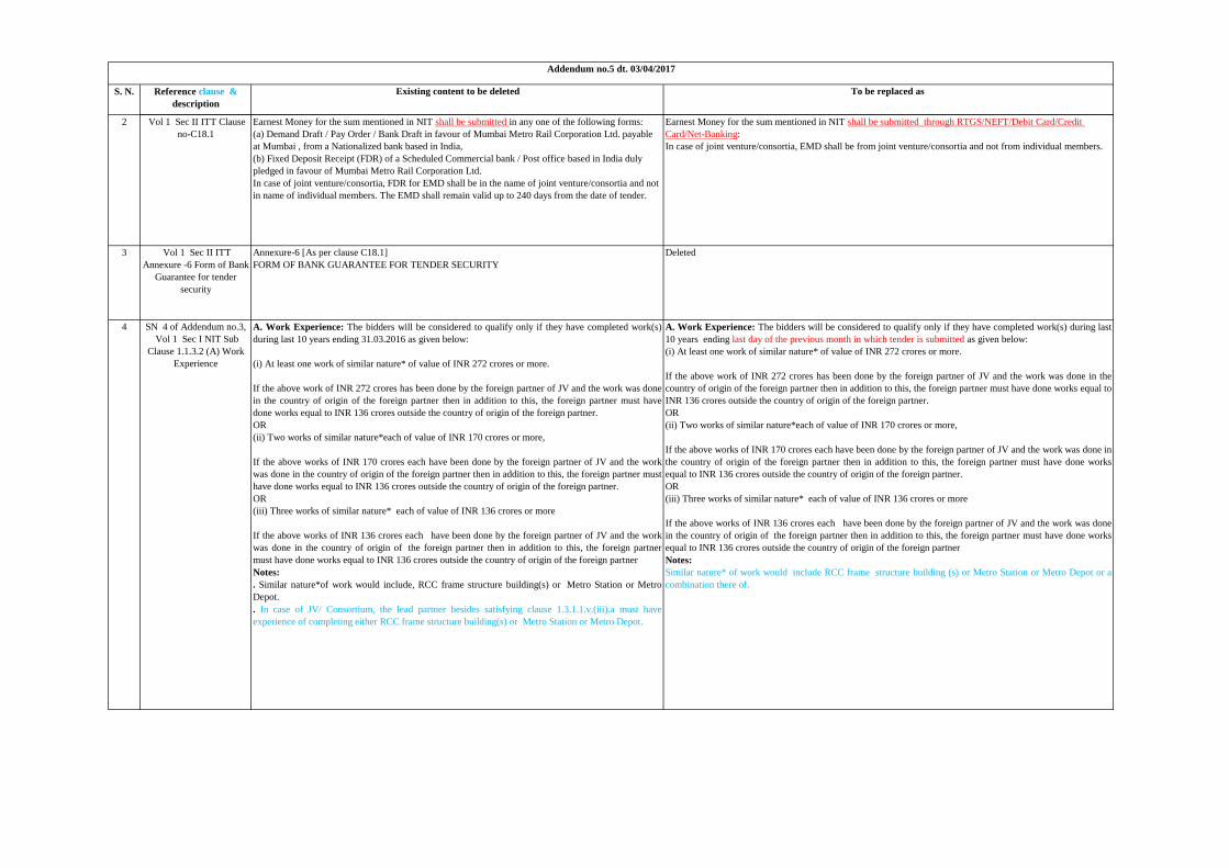
name of work:- construction of the depot cum … no 5-appendix.pdf · s. n. reference clause &...
TRANSCRIPT

S. N. Reference clause &
description
Existing content to be deleted To be replaced as
*Please also refer published Addendum no.1 dt. 14/02/2017, Addendum no.2 dt. 22/02/2017 & Addendum no.3 dt. 08/03/2017 & addendum no.4 dt. 17/03/2017
Name of work:- Construction of the Depot cum Workshop Buildings, Metro station building, sub-way, earthwork and all associated works at Aarey colony, for the Mumbai Metro Line -3 Project ”
Addendum no.5 dt. 03/04/2017
1 SN 11 of Addendum no.1,
Vol 1 NIT Subclause
1.1.10 (II)Earnest Money
ii. Earnest Money Deposit / Tender Security :-
Earnest money deposit for this work will be Rs. 3,40,35,000/- only.The Tenderer shall submit with his
Tender a Tender Security for the sum mentioned in NIT in the following forms:
a. An amount of INR 1,00,000 (Rupees one Lac) Through RTGS/NEFT/Net Banking/Credit card/Debit
Card;
b.For the balance Tender Security, Irrevocable bank guarantee issued by a Scheduled Commercial Bank
(including Scheduled Commercial Foreign Banks) in India in the form given in Annexure 6 to these
Instruction to Tenderers (ITT). In case of joint venture or consortium, the Bank Guarantee for Tender
Security shall be from JV/consortium and not from individual members, or an irrevocable Letter of
Credit, or a Demand Draft / Pay Order / Bank Draft in favour of Mumbai Metro Rail Corporation Ltd.
payable at Mumbai from a Scheduled Commercial bank based in India or Fixed Deposit receipt of a
Scheduled Commercial Bank / post office based in India duly pledged in faour of Mumbai Metro Rail
Corporation Ltd. The Tender Security shall remain valid for a period of 56 days beyond the validity
period for the tender.
The tenderer shall upload scanned copy of the Tender Security as part of Envelope A on the online
MMRDA e-tendering portal only. The bidder shall submit the original Tender Security, two days before
the Date of opening of Envelope A, up to 15.00 hrs at the office of the Chief Project Manager-5,
MMRC Ltd. Plot No. 13, NaMTTRI Building, E-Block,Bandra Kurla Complex Bandra –East, Mumbai-
400051, India
ii. Earnest Money Deposit / Tender Security :-
Earnest money deposit for this work will be Rs. 3,40,35,000/- only.
In case of joint venture/consortia, EMD shall be from joint venture/consortia and not from individual members.
EMD can be paid by using two Mode of Payment:
a) Online payment gateway (i.e. Debit Card/Credit Card/Net-Banking)
b) RTGS / NEFT mode using the System Generated Unique Challan (Account No for EMD
transaction for this particular Tender is mentioned in the Challan)
Payment procedure for NEFT/RTGS:
EMD Payment as mentioned above has to be made through RTGS / NEFT mode using the System Generated
Challan. Bidders should ensure that the payment of the EMD is made at-least 5 working days prior to
the last date of Bid Preparation and Submission of the Tender Schedule to have seamless submission.
Bidders need to upload scanned copy of EMD paid receipt during bid preparation.
Bidders failing to complete the payment of EMD using the above mentioned process of RTGS /NEFT or Online
payment gateway after downloading the system generated challan will not be able to submit their bids.
EMD Refund:
Bidders should mention the beneficiary details for EMD refund in the Earnest Money Deposit Form for fields
marked as details required for Refund. MMRDA or e-Tendering Service Provider will not be liable for delays
caused in EMD refund due to incorrect beneficiary details.
The earnest money deposit of unsuccessful bidders will be refunded either physically by cheque/pay order or
through RTGS, NEFT mode only after finalization of the tender for which the above refund details are required.
Bidders should also upload scanned copy of cancelled cheque along with refund letter for refund of their EMD
payment. In case of successful bidder, amount of the earnest money deposit may be transferred towards part of
the security deposit to be paid after the award of the work, if he intends to do so in writing.
Kindly note that transfer of funds to MMRDA’s account through NEFT / RTGS mode, from the Bidders’ ICICI
accounts is currently not possible. In case of funds transfer through NEFT / RTGS,
Bidders are requested to transfer from any other bank (excluding ICICI Bank).
• EMD Refund Account should remain active until tender is awarded.
• EMD Refund will happen only after Awarding or Cancellation of tenders.
*Note:
i) The entire EMD amount shall have to be paid in single amount as the system will not accept multiple part
payments otherwise the bid shall be rejected.
ii) If any bidder has already paid Rs. 1,00,000/- amount, the same will be refunded in due course.
MUMBAI METRO RAIL CORPORATION LTD (MMRC)
S. N. Reference clause &
description
Existing content to be deleted To be replaced as
Addendum no.5 dt. 03/04/2017
2 Vol 1 Sec II ITT Clause
no-C18.1
Earnest Money for the sum mentioned in NIT shall be submitted in any one of the following forms:
(a) Demand Draft / Pay Order / Bank Draft in favour of Mumbai Metro Rail Corporation Ltd. payable
at Mumbai , from a Nationalized bank based in India,
(b) Fixed Deposit Receipt (FDR) of a Scheduled Commercial bank / Post office based in India duly
pledged in favour of Mumbai Metro Rail Corporation Ltd.
In case of joint venture/consortia, FDR for EMD shall be in the name of joint venture/consortia and not
in name of individual members. The EMD shall remain valid up to 240 days from the date of tender.
Earnest Money for the sum mentioned in NIT shall be submitted through RTGS/NEFT/Debit Card/Credit
Card/Net-Banking:
In case of joint venture/consortia, EMD shall be from joint venture/consortia and not from individual members.
3 Vol 1 Sec II ITT
Annexure -6 Form of Bank
Guarantee for tender
security
Annexure-6 [As per clause C18.1]
FORM OF BANK GUARANTEE FOR TENDER SECURITY
Deleted
A. Work Experience: The bidders will be considered to qualify only if they have completed work(s) during last
10 years ending last day of the previous month in which tender is submitted as given below:
(i) At least one work of similar nature* of value of INR 272 crores or more.
If the above work of INR 272 crores has been done by the foreign partner of JV and the work was done in the
country of origin of the foreign partner then in addition to this, the foreign partner must have done works equal to
INR 136 crores outside the country of origin of the foreign partner.
OR
(ii) Two works of similar nature*each of value of INR 170 crores or more,
If the above works of INR 170 crores each have been done by the foreign partner of JV and the work was done in
the country of origin of the foreign partner then in addition to this, the foreign partner must have done works
equal to INR 136 crores outside the country of origin of the foreign partner.
OR
(iii) Three works of similar nature* each of value of INR 136 crores or more
If the above works of INR 136 crores each have been done by the foreign partner of JV and the work was done
in the country of origin of the foreign partner then in addition to this, the foreign partner must have done works
equal to INR 136 crores outside the country of origin of the foreign partner
Notes:
Similar nature* of work would include RCC frame structure building (s) or Metro Station or Metro Depot or a
combination there of.
A. Work Experience: The bidders will be considered to qualify only if they have completed work(s)
during last 10 years ending 31.03.2016 as given below:
(i) At least one work of similar nature* of value of INR 272 crores or more.
If the above work of INR 272 crores has been done by the foreign partner of JV and the work was done
in the country of origin of the foreign partner then in addition to this, the foreign partner must have
done works equal to INR 136 crores outside the country of origin of the foreign partner.
OR
(ii) Two works of similar nature*each of value of INR 170 crores or more,
If the above works of INR 170 crores each have been done by the foreign partner of JV and the work
was done in the country of origin of the foreign partner then in addition to this, the foreign partner must
have done works equal to INR 136 crores outside the country of origin of the foreign partner.
OR
(iii) Three works of similar nature* each of value of INR 136 crores or more
If the above works of INR 136 crores each have been done by the foreign partner of JV and the work
was done in the country of origin of the foreign partner then in addition to this, the foreign partner
must have done works equal to INR 136 crores outside the country of origin of the foreign partner
Notes:
. Similar nature*of work would include, RCC frame structure building(s) or Metro Station or Metro
Depot.
. In case of JV/ Consortium, the lead partner besides satisfying clause 1.3.1.1.v.(iii).a must have
experience of completing either RCC frame structure building(s) or Metro Station or Metro Depot.
SN 4 of Addendum no.3,
Vol 1 Sec I NIT Sub
Clause 1.1.3.2 (A) Work
Experience
4

S. N. Reference clause &
description
Existing content to be deleted To be replaced as
Addendum no.5 dt. 03/04/2017
6 Vol 1 of NIT Sub Clause
1.1.2.1 The Project
The Project
Mumbai Metro Line 3 (MML3) shall require a dedicated Depot-cum-Workshop facility for catering to
operational & maintenance requirement of its fleet of 35 Rakes of 8 cars each. The proposed Depot is
located over a plot of area of about 30.2 hectare at Aarey Colony, close to SEEPZ station of the
alignment. However, the Depot is planned over an area of about 25 hectares, including ramp. Based on
Operational and Maintenance Plan, Depot for MML3 project shall be implemented
The Project
Mumbai Metro Line 3 (MML3) shall require a dedicated Depot-cum-Workshop facility for catering to
operational & maintenance requirement of its fleet of 31 Rakes of 8 cars each. The proposed Depot is located
over a plot of area of about 30.2 hectare at Aarey Colony, close to SEEPZ station of the alignment. However,
the Depot is planned over an area of about 25 hectares, including ramp. Based on Operational and Maintenance
Plan, Depot for MML3 project shall be implemented
7 Vol 1 of NIT Sub Clause
1.1.3.1 B .Finicial Standing
B. Financial Standing: The tenderers will be qualified only if they have minimum financial
capabilities as below:
(i) T1 – Liquidity:
(ii) T2 - Profitability
T3 -Net Worth:
(iii) T4 - Annual Turnover:
B. Financial Standing: The tenderers will be qualified only if they have minimum financial capabilities as below:
(i) T1 – Liquidity:
(ii) T2 - Profitability
(iii)T3 -Net Worth:
(iv) T4 - Annual Turnover:
8 Vol 1 of NIT Sub Clause
1.1.3.1 B .Finicial Standing
Notes
Notes:
· Financial data for latest last five audited financial years has to be submitted by the tenderer in
Appendix-18 of FOT along with audited balance sheets. The financial data in the prescribed format
shall be certified by Chartered Accountant with his stamp and signature in original with membership
number. In case audited balance sheet of the last financial year is not made available by the bidder, he
has to submit an affidavit certifying that ‘the balance sheet has actually not been audited so far’. In such
a case the financial data of previous ‘4’ audited financial years will be taken into consideration for
evaluation. If audited balance sheet of any year other than the last year is not submitted, the tender may
be considered as non-responsive.
· Where a work is undertaken by a group, only that portion of the contract which is undertaken by the
concerned applicant/member should be indicated and the remaining done by the other members of the
group be excluded. This is to be substantiated with documentary evidence.
Notes:
· Financial data for latest last five audited financial years has to be submitted by the tenderer in Appendix-18 of
FOT along with audited balance sheets. The financial data in the prescribed format shall be certified by
Chartered Accountant with his stamp and signature in original with membership number. In case audited balance
sheet of the last financial year is not made available by the bidder, he has to submit an affidavit certifying that
‘the balance sheet has actually not been audited so far’. In such a case the financial data of previous ‘4’ audited
financial years will be taken into consideration for evaluation. If audited balance sheet of any year other than the
last year is not submitted, the tender may be considered as non-responsive.
· Where a work is undertaken by a group, only that portion of the contract which is undertaken by the concerned
applicant/member should be indicated and the remaining done by the other members of the group be excluded.
This is to be substantiated with documentary evidence.
· It is clarified that wherever latest last financial year/last financial year/audited financial year has been stipulated
it means financial year ending 31-03-2016
5 SN 6 of Addendum 3, Vol
1 Clause no C2.3(i) ii(a)
of ITT sec-II page 17
(i) Following information shall be furnished: information related to RCC frame structure building(s) or
Metro Station or Metro Depot & Industrial steel shed and Earth work.
(i) Extent of participation by each member of the consortium in terms of percentage of the value of the
proposed Contract.
Member % of participation
A
B
C
(ii) The tenderer should supply the following information, separately for each member of the
consortium.
(a) Works executed of RCC frame structure building(s) or Metro Station or Metro Depot & Industrial
steel shed, and Earth work ,in each year during the last 10 years (for work experience) & last 5 years
upto date of submission (for key activity experience) (in Rs. equivalent/quantity units)as stipulated.
(b) Value of the commitments and on-going works, on yearly basis, to be completed during the next 30
months from the first date of the month of the tender submission.
Above (a) should be updated to price level of 01.04.2017 by assuming 2% inflation on foreign
currency and 5% on Indian currency. The exchange rate of foreign currency shall be applicable 28 days
before the date of submission
(i) Following information shall be furnished: information related to RCC frame structure building(s) or Metro
Station or Metro Depot & Industrial steel shed and Earth work.
(i) Extent of participation by each member of the consortium in terms of percentage of the value of the proposed
Contract.
Member % of participation
A
B
C
(ii) The tenderer should supply the following information, separately for each member of the consortium.
(a) Works executed of RCC frame structure building(s) or Metro Station or Metro Depot & Industrial steel shed
,and Earth work ,in each year during the last 10 years ending last day of the previous month in which tender is
submitted (for work experience) & last 5 years up to date of submission( for key activity experience) in Rs
equivalent/quantity units as stipulated
(b) Value of the commitments and on-going works, on yearly basis, to be completed during the next 30 months
from the first date of the month of the tender submission.
Above (a) should be updated to price level of 01.04.2017 by assuming 2% inflation on foreign currency and 5%
on Indian currency. The exchange rate of foreign currency shall be applicable 28 days before the date of
submission

S. N. Reference clause &
description
Existing content to be deleted To be replaced as
Addendum no.5 dt. 03/04/2017
9 Vol 1 of NIT Sub Clause
1.1.3.3 B .Bid Capacity
Criteria Notes
Notes: Financial data for latest last five financial years has to be submitted by the tenderer in Appendix-
15 of FOT along with audited financial statements. The financial data in the prescribed format shall be
certified by the Chartered Accountant with his stamp and signature in original with membership num
· Value of existing commitments for on-going construction works during period of 30 months w.e.f.
first day of the month of submission of the tender, has to be submitted by the tenderer in Appendix-16
of FOT. These data shall be certified by the Chartered Accountant with his stamp and signature in
original with membership number
·In case of a group, the above formula will be applied to each member to the extent of his proposed
participation in the execution of the work .If the proposed % participation is not mentioned, then equal
participation will be assumed
Notes: Financial data for latest last five financial years has to be submitted by the tenderer in Appendix-15 of
FOT along with audited financial statements. The financial data in the prescribed format shall be certified by the
Chartered Accountant with his stamp and signature in original with membership num
· Value of existing commitments for on-going construction works during period of 30 months w.e.f. first day of
the month of submission of the tender, has to be submitted by the tenderer in Appendix-16 of FOT. These data
shall be certified by the Chartered Accountant with his stamp and signature in original with membership number
·In case of a group, the above formula will be applied to each member to the extent of his proposed
participation in the execution of the work .If the proposed % participation is not mentioned, then equal
participation will be assumed
· It is clarified that wherever latest last financial year/last financial year/audited financial year has been stipulated
it means financial year ending 31-03-2016
10 Vol 1 In FOT-APPENDIX
15 in Heading & Column 2
(As per clause E4.2) FINANCIAL DATA (WORK DONE DURING THE LATEST LAST FIVE
FINANCIAL YEARS ) & Total value of work done pertaining to audited financial statements
(As per NIT clause 1.1.3.2 B (iv)) FINANCIAL DATA (CONSTRUCTION WORK DONE DURING THE
LAST FIVE FINANCIAL YEARS) & Total turnover of construction work done pertaining to audited financial
statements
11 Vol 1 FOT Appendix 15A FORM OF TENDER APPENDIX 15 A ENTIRE FORM DELETED
12 Clause 1.1.3.1 B of NIT
Page no 6
(i) T4 - Annual Turnover:The average annual turnover from construction of last five
financial years.
should be > INR136crores.
As given in Appendix 15 A
(i) T4 - Annual Turnover:The average annual turnover from construction work of last five financial
years.
should be > INR136crores.
As given in Appendix 15
13 Vol-1 FOT -APPENDIX
16 Heading of 10th i.e. last
column
Value of work to be done in 2019-20( Ist April 2019 to 31st March 2020) Value of work to be done in 2019-20( 1st April 2019 to 30th Sept 2019)
14 Vol-1FOT -APPENDIX 17
In Heading of Table
( considering escalation as per Clause 1.1.3.2 of Notes Bullet no.3 of NIT) ( considering inflation as per Clause 1.1.3.2 A)
15 SN 24 of Addendum no.1
Vol 3 Appendix 19
System Interface
Management
Appendix 19(Revised) SYSTEM INTERFACE MANAGEMENT Appendix 19( Revision 2) SYSTEM INTERFACE MANAGEMENT

Contract MM3-CBS-CWD
Part 2: Employer’s Requirement
Section VI A – General Specifications: Appendix 19
Page | i
BIDDING DOCUMENTS
MUMBAI METRO LINE 3
EMPLOYER’S REQUIREMENTS
GENERAL SPECIFICATIONS
Part 2
Section VI-A
Appendix 19(Revision 2)
SYSTEM INTERFACE MANAGEMENT
January 2017
MUMBAI METRO RAIL CORPORATION LIMITED
MMRDA BUILDING,
Bandra Kurla Complex,Bandra (East),
Mumbai – 400 051, India.

Contract MM3-CBS-CWD
Part 2: Employer’s Requirement
Section VI A – General Specifications: Appendix 19
Page | ii
MUMBAI METRO LINE 3
Part 2
Section VI-A
Appendix 19
SYSTEM INTERFACE MANAGEMENT
Issuing entity Discipline Area Document No. Revision Index
GCC 301 P00 1600033 H

Contract MM3-CBS-CWD
Part 2: Employer’s Requirement
Section VI A – General Specifications: Appendix 19
Page | iii
DOCUMENT / DRAWING TECHNICAL
VERIFICATION AND REVISION RECORD
PROJECT NAME Mumbai Metro Rail Line 3
*DOC / NO. GCC-MMR-301-P00-1600033 DATE OF FIRST ISSUE 02-02-2016
*DOC / TITLE System Interface Management Requirement
REV
No.
DATE OF
ISSUE/REV
.
DESCRIPTION PREPARED/
DESIGNED
CHECKE
D
APPROVE
D
A 02-02-2016 First Diffusion BDE HFL RJM
B 16-02-2016 Udated for RS RFP BDE HFL RJM
C 18-02-2016 Official Diffusion BDE HFL RJM
D 28/03/2016
Updated with Aarey
Station Interface Sheet
and Rolling Stock
BDE HFL RJM
E 06/05/2016
Attachement N
Updated with all
Interface Sheet with
Rolling Stock
BDE HFL RJM
F 06/05/2016
Attachement N to be
completed/Modifyed
for others Contracts by
Key Experts
BDE HFL RJM
G 30/08/2016 Attachment E and F
updated
PNK BDE RJM
H
18/01/2017
Attachement E, F2 &
M updated. Minor
changes and
corrections done.
PNK
BDE
RJM

Contract MM3-CBS-CWD
Part 2: Employer’s Requirement
Section VI A – General Specifications: Appendix 19
Page | iv
TABLE OF CONTENTS
EMPLOYER’S REQUIREMENTS ........................................................................................................1
1. DEFINITIONS AND ABBREVIATIONS .......................................................................... 1
2. INTRODUCTION ........................................................................................................... 3
3. CO-ORDINATION .......................................................................................................... 5
3.1 CONTRACTOR’S CO-ORDINATION RESPONSIBILITIES ......................................................... 5
3.2 SITE CO-ORDINATION & ATTENDANCE ............................................................................. 5
4. INTERFACE ................................................................................................................... 7
4.1 CO-ORDINATION OF CONTRACTOR’S SCOPE OF WORK ...................................................... 7
4.2 INTERFACING CONTRACTORS ........................................................................................... 7
4.3 INTERFACING CONTRACTORS - COMMUNICATIONS AND INFORMATION EXCHANGE ............ 8
4.4 RESOLUTION OF CO-ORDINATION DIFFICULTIES ............................................................. 10
4.5 INTERFACE PERFORMANCE ............................................................................................ 11
5. CONTRACTOR’S INTERFACE MANAGEMENT SYSTEM ......................................... 11
5.1 INTERFACE MANAGEMENT SYSTEM ................................................................................ 11
5.2 INTERFACE MANAGEMENT TEAM ................................................................................... 12
6. INTERFACE MANAGEMENT PLAN & INTERFACE MANAGEMENT PROGRAMME13
6.1 GENERAL ....................................................................................................................... 13
6.2 INTERFACE MANAGEMENT PROGRAMME (IMPG) ............................................................ 13
6.3 INTERFACE MANAGEMENT PLAN (IMP) .......................................................................... 13
6.4 REQUIREMENTS FOR THE INTERFACE MANAGEMENT PROGRAMME & INTERFACE
MANAGEMENT PLAN ...................................................................................................... 14
6.5 INTERFACE SPECIFICATION. ............................................................................................ 14
6.6 CONTRACTOR’S SUBMISSIONS ......................................................................................... 15
6.7 MONITORING THE PROGRESS OF INTERFACE AGREEMENTS ............................................. 16
7. INTERFACE COORDINATION SHEET (ICS) .............................................................. 17
8. COORDINATION DRAWINGS ..................................................................................... 17
8.1 GENERAL ....................................................................................................................... 17
8.2 COMBINED SERVICES DRAWING (CSDS) AND STRUCTURAL E&M DRAWINGS (SEMS) ....... 18
8.3 INTERFACE DRAWINGS ................................................................................................... 19
8.4 AS CONSTRUCTED DRAWINGS ......................................................................................... 19
9. ATTACHMENTS .......................................................................................................... 19
ATTACHMENT A - FLOW CHART FOR CREATION / ELABORATION OF INTERFACE COORDINATION
SHEET .................................................................................................................................... 19
ATTACHMENT B - FLOW CHART FOR PROGRESS MONITORING OF INTERFACE AGREEMENTS ..... 22
ATTACHMENT C – INTERFACE SPECIFICATION FORM ................................................................. 23
ATTACHMENT D - MASTER INTERFACE LOG (MIL) - EXAMPLE ................................................. 24
ATTACHMENT E - MASTER INTERFACE MATRIX (MIM) ............................................................ 25
ATTACHMENT F PART 1 - INTERFACE COORDINATION SHEET EXAMPLE .................................... 26
ATTACHMENT F PART 2 - INTERFACE COORDINATIONSHEET-CONTRACT CODES ....................... 27
ATTACHMENT F PART 3 - INTERFACE COORDINATION SHEET- STATUS CODES ........................... 28
ATTACHMENT G – CONFIRMATION OF COORDINATION FORM ................................................... 29
ATTACHMENT H - REVIEW AND COMMENT ON ALL DESIGN / INTERFACE SUBMITTALS TEMPLATE30
ATTACHMENT K - GUIDANCE NOTES FOR THE PREPARATION OF INTERFACE MANAGEMENT
PROGRAMME. ................................................................................................................ 31
ATTACHMENT L - GUIDANCE NOTES FOR THE PREPARATION OF INTERFACE MANAGEMENT PLAN.31
ATTACHMENT M - INTERFACE SHEET (TEMPLATE) ................................................................... 33

Contract MM3-CBS-CWD
Part 2: Employer’s Requirement
Section VI A – General Specifications: Appendix 19
Page | v
ATTACHMENT N – INDICATIVE INTERFACE SHEET FOR CONTRACT MM3-CBS-CWD.......34
N1 – INDICATIVE INTERFACE SHEET OF TRACK WORKS(TWK) AND DEPOT CIVIL WORKS
STATION(CWD)……………………………………………………35
N2 – INDICATIVE INTERFACE SHEET OF TRACK WORKS(TWK) AND DEPOT CIVIL WORKS(CWD) ........38
N3- INDICATIVE INTERFACE SHEET OF DEPOT CIVIL WORKS(CWD) AND ROLLING STOCK(RST)...........42
N4 - INDICATIVE INTERFACE SHEET OF OVERHEAD CONTACT SYSTEM (OCS) AND DEPOT CIVIL
WORKS(CWD).......................................................45
N5- INDICATIVE INTERFACE SHEET OF SIGNALLING & TELECOM(STPT) AND DETAILED DESIGN
CONSULTANT (DDC)………….49
N6- INDICATIVE INTERFACE SHEET OF SIGNALLING & TELECOM (STPT) AND DEPOT CIVIL WORKS
(CWD)………………………………………52
N7- INDICATIVE INTERFACE SHEET OF UNDERGROUND TUNNEL(UGC-07) AND DEPOT CIVIL
WORKS………………55
N8 – INDICATIVE INTERFACE SHEET OF DEPOT CIVIL WORKS(CWD) AND DEPOT E&M
STATION(DEM)…………………………………58
N9 – INDICATIVE INTERFACE SHEET OF DEPOT CIVIL WORKS (CWD) AND PYLON TERMINATION
CONTRACTOR(PYL)…………………63
N10 – INDICATIVE INTERFACE SHEET OF DEPOT EQUIPMENT(DEQ) AND DETAILED DESIGN
CONSULTANT (DDC)……………………….65
N11 – INDICATIVE INTERFACE SHEET OF DETAILED DESIGN CONSULTANT (DDC) AND DEPOT CIVIL
WORKS(CWD)…………………….67

Contract MM3-CBS-CWD
Part 2: Employer’s Requirement
Section VI A – General Specifications: Appendix 19
GCC-MMR-301-P00-160GCC-3 Page 1 of 68
EMPLOYER’S REQUIREMENTS
DESIGN AND CONSTRUCTION INTERFACE MANAGEMENT
1. DEFINITIONS AND ABBREVIATIONS
1.1 Chief Interface Coordinator(CIC) means a suitably qualified person, assigned by a
Contractor, who is the Team Leader responsible for administerating, monitoring, managing,
supervising and resolving all interface issues between Interfacing Contractors for the Mumbai
Metro Line 3 Project.
1.2 General Consultant Interface Manager (GCIM) means the responsible person,
assigned by the PM who is the main coordinatorof all project interfaces with RE and
contractors CIC. He shall coordinate the overall technical point of the project from the point
of view of proper integration of a System and Civil Work in all technical and operational
areas to ensure delivery of safe and coherant metro system. He shall attend coordination
meetings with all project contractor’sCIC, and communicate issues & concerns relating to
coordination, approvals and systems & Civil interfaces.
1.3 Combined Services Drawings (CSD)means the drawings produced by the Civil Work
Contractor, showing the locations, sizes and details of all of the Contractor’s equipment,
cable containment, pipes, etc. These drawings are to be used to enable all equipment, pipes,
cables, etc. to be installed without conflict and to enable future changes or modifications to be
performed without impacting the existing installation.
1.4 Interface means the region of interaction across the common boundary between two
adjacent but separately managed and controlled parts of the Project. The coordination and
management of the interaction regions is necessary to ensure that the overall scope and
definition of the Project works is complete and seamless across all such boundaries.
1.5 Interfacing Contractors means any of the following whose activities or the works they
are engaged to carry out in any way or at any time affect or are affected by the Works:
a. Project Contractors and design or specialist consultants engaged on the Project from
time to time by the Employer, the Government of Republic of India, the Government of
Maharashtra or the utility providers;
b. utility providers;
c. developers or franchisees appointed on the Project from time to time by the Employer;
d. subcontractors of any tier of the contractors within category (a) above, and contractors
and subcontractors of any tier of utility providers, developers and franchisees within
categories (b) and (c) above;
e. provided that the definition shall exclude the Contractor and his subcontractors of any
tier in relation to the Works and in any other capacity which would otherwise fall
within categories (a) to (d) above in relation to other works.
1.6 Interface Coordination Sheet (ICS) means a document produced by the Contractor
which defines the integration and interfaces between his contract and the Interfacing
Contractors employed on the Project.
1.7 Interface Management Programme (IMPG) means the programme produced by the
Contractor, developed and updated on a quarterly basis, which describes the sequence and
timing of each of the Interfacing Contractor’s scope of work, and clearly describes
dependencies between his Works and the work of the Interfacing Contractors.

Contract MM3-CBS-CWD
Part 2: Employer’s Requirement
Section VI A – General Specifications: Appendix 19
GCC-MMR-301-P00-160GCC-3 Page 2 of 68
1.8 Interface Management Plan (IMP) means the Report prepared by the Contractor,
developed and updated on a quarterly basis that provides a clear description of his interfaces
both sequentially and technically as specified in the Contract. The report will be reviewed in
accordance with this procedure and is a pre-requisite to the PM’s Notice of No Objection.
1.9 Interface Specification (IS)means the specification document developed by the Lead
Contractor for the interfacing part of his project on the basis of, and by integrating into his
design, the information provided by the Interfacing Contractors in accordance with the
interface agreements as contained in the ICS. The Interface specification needs to be agreed
upon by both the Lead Contractor and the Interfacing Contractor’s before it is submitted to
thePM for Notice of No Objection.
1.10 Master Interface Log (MIL) is an electronic Log of identified interfaces maintained by
the Interface SupportingTeam (IST) in the format given in Attachement D, showing (among
others) updated status and priority rating of each interface agreement, by its unique serial
number, for the purpose of monitoring the progress of Interface agreements from inception to
close-out.
1.11 Master Interface Matrix (MIM) means the document developed by the PM, which may be
updated, and/or expanded to include additional Interfacing Contractors, by the PM as the
Project progresses. The purpose of the Master Interface Matrix is to allocate which
Interfacing Contractors are the lead party(s) for each contract.
1.12 Resident Engineer (RE)means the General Consultant Discipline Key Chief Resident
Engineer, who is incharge of the monitor progress in interface agreements of his contractor
with other interfacing contractors, on site in accordance with the IMP/IMPG and resolve
interface issues which the interfacing contractors are unable to resolve among themselves. He
shall identify interface issues that cannot be resolved at his level and alert the GCIM about
them in the course of his day-to-day interactions with the GCIM for taking further action.He
shall pursue the matter till the required information is exchanged in time.
1.13 Structural, Electrical and Mechanical Drawings (SEM) means those drawings
produced by the Civil Work Contractor, showing the locations, sizes and details for all
structural openings, plinths, embedments, sumps, floor chases, etc. required for the
installation of all equipment, cable trays, pipes, etc.
1.14 Zone of Interface means where two or more components of the railway provided by two or
more Interfacing Contractors combine to provide a single element.
Acronyms and abbreviation will appear immediately after the first time the words are used.
Thereafter, only the acronyme or abbreviation will be used in the Appendix 19 .
Acronym Description
CIC Chief Interface Coordinator (of the Contractor)
CSD Combined Services Drawing
GC General Consultant for MML3
GCIM General Consultant Interface Manager
ICS Interface Coordination Sheet – Monthly report
IS Interface Specification
IST Interface Support Team

Contract MM3-CBS-CWD
Part 2: Employer’s Requirement
Section VI A – General Specifications: Appendix 19
GCC-MMR-301-P00-160GCC-3 Page 3 of 68
IST TL Interface Support Team Team Leader (Project Rail Systems Manager, a
Member of the Project Management Team, discharges this function.)
IMP Interface Management Plan
IMPG Interface Management Programme
MIM Master Interface Matrix
MIL Master Interface Log
MMRC Mumbai Metro Rail Corporation
MOM Minute Of Meeting
PM Project Manager as Employer’s Representative
RE Resident Engineer as Project Manager’s Representative
SEM SructuralElectical and Mechanical Drawings
2. INTRODUCTION 2.1 Interface and co-ordination of the Works will include the co-ordination of all design,technical
and programming matters with the various Interfacing Contractors to achieve fully co-ordinated
construction and installation of the facilities.
2.2 This Appendix 19 describes the Contractor’s responsibilities with regard to interface
management and coordination with those Interfacing Contractors and who are responsible for
undertaking work, which interfaces with the Contract. The Contractor’s responsibility for
interface coordination shall include currently defined Interfacing Contractors and those
whoshall be identified in the future. This responsibility is not limited to a particular number of
Interfacing Contractors.
2.3 The Contractor’s responsibility for interface co-ordination shall include identification of
Interfacing Contractors, subcontractors, including subcontractors within his own Contract.and
those who shall be subsequently identified during the course of the Contract for whom the
Contractor will need to interface and coordinate the Works. This in no way detracts from the
fact that the Contractor remains solely responsible for identifying, liaising, and co-ordinating
with all Interfacing Contractors in relation to the Works.
2.4 The PMwill monitor and oversee the interface Management activities by the contractor and will
specifically provide direction or information in the following circumstances.
a) When the interfacing contract has not yet been awarded
b) When common agreement cannot reached between the interfacing parties
c) When it is in the interest of the project programme, quality or safety to issue direction.
Direction or information provided by the employer representative where ever necessary,
shall not in any way relieve the contractor of his full responsibility to ensure the correctness,
accuracy and suitability of the interface implementation and required specification.
2.5 The Contractor shall at all times use his best endeavours to resolve all interfaces applicable to
the Contract and shall be proactive in seeking out interface issues and their solutions.
2.6 The Contractor shall ensure that all of the above Interface requirements are included in his
Interface Management Plan, refer to Clause 6 of this Appendix 19. Flow charts illustrating the
process of entering into an Interface agreement/desagreement and Monitoring its progress with
the help of the Interface Coordination Sheet are provided as Attachment A(Flowchartcreation

Contract MM3-CBS-CWD
Part 2: Employer’s Requirement
Section VI A – General Specifications: Appendix 19
GCC-MMR-301-P00-160GCC-3 Page 4 of 68
/elaboration of theInterface Coordination Sheet) andAttachment B (Flowchart for Progress
Monitoring of Interface Agreement)of this Appendix 19. And Figure 1 gives a schematic
presentation of the Interface Communication and Coordination processes between the various
role-players in the Project.
2.7 The Contractor’s internal sub-contractors’ and suppliers’ interfaces are the sole responsibility of
the Contractor and are not covered in this Appendix 19. However, the Contractor shall co-
ordinate and manage these interfaces in such a way as to identify and cater for the requirements
of the Interfacing Contractors and domestic interfaces, including but not limited to, the
avoidance of clashes and sequencing of Works. The Contractor shall compile an internal IMP
for his own use, a copy of which shall be furnished to the PMon request at any time.
Liaison Status
Action Report Action
Status Report
and Meetings
Liaison Status
Feedback Monthly
Report
Feedback
&
THE EMPLOYER
Project Manager
And GCIM + RE
CONTRACTOR’S
INTERFACING
MANAGEMENT
TEAM
CONTRACTOR’S
DESIGN
&
CONSTRUCTION
TEAM
OTHER
INTERFACING
CONTRACTORS
INTERFACING
CONTRACTORS
Regular Site
Meetings Status /
Action Report
Contractor’s Organisation
Figure 1 – Interface Communication and Coordination Model
INTERFACING*
Parties &Stakeolder
Operator &Maintener
INTERFACING *
Interfacing Parties could be: Utility,Telephone Operator, Water, Electricity….
Interfacing Stakeholder could be: Safety Autority, ISA, RDSO,CMRS, Fire, Police,
EIG.
Status Report
and Meetings

Contract MM3-CBS-CWD
Part 2: Employer’s Requirement
Section VI A – General Specifications: Appendix 19
GCC-MMR-301-P00-160GCC-3 Page 5 of 68
3. CO-ORDINATION
3.1 Contractor’s Co-Ordination Responsibilities
The Contractor shall co-ordinate with the PM (GCIM and/or RE) and shall be required to
attend meetings on issues appertaining to Government authorities and utility agencies
regarding the services/facilities to be provided by them for the project.
The Contractor shall ensure that the work of all Interfacing Contractors can be carried out in
accordance with the Interface Management Plan prepared by the Contractor.
3.2 Site Co-Ordination & Attendance
This Chapter 3.2 describes what the Civil Work Contractor shall do.
3.2.1. The Civil Work Contractor shall, at his own cost, provide all attendance on and co-
ordination with Interfacing Contractor. The following items are not a comprehensive or
exhaustive list of the co-ordination or interface attendance items to be provided for the
Interfacing Contractor’s use, but are intended to provide an outline of the content of
amenities, services and facilities for which the Civil Work Contractor is responsible:
a) Single point of contact for meetings, actions, planning, scheduling and co-
ordinating.
b) Site access
The Civil Work Contractor shall co-ordinate with the Interfacing Contractor and
provide access and use of temporary access roads to and from and within the Site.
The Civil Work Contractor shall co-ordinate all vehicle movements, deliveries and
other activities with the Interfacing Contractor so as to ensure conflicts of use will
be controlled on and around the Site.
c) Storage and Accommodation area
The Interfacing Contractor will require limited temporary site accommodation and
storage areas. The Civil Work Contractor shall agree with the Interfacing Contractor
access and areas for storage and temporary site accommodation prior to their
commencing work on Site.
d) Work space requirement and sequence of Works
e) Shared use of Civil Work Contractor’s scaffold
The Civil Work Contractor shall co-ordinate with the Interfacing Contractor and
provide free use and shared access of his erected scaffolding, ladders and hoists
should they be available at the time the Interfacing Contractor requires to use them.
Not withstanding this requirement, the Civil Work Contractor shall at all times
remain responsible for the management of safety and the maintenance of such
scaffolding, ladders and landings. The Civil Work Contractor will not be required to
adapt or erect access scaffolds specifically for the use of Interfacing Contractor.
If the Interfacing Contractor erects and uses his own scaffold he will be required to
adhere to the Civil Work Contractor’s safety rules and access routing for equipment
and materials. The Civil Work Contractor shall ensure that all scaffolds of
Interfacing Contractor are erected in a safe manner and are subject to permits for
use issued by the Contractor.
f) Setting out control points
g) Access Openings

Contract MM3-CBS-CWD
Part 2: Employer’s Requirement
Section VI A – General Specifications: Appendix 19
GCC-MMR-301-P00-160GCC-3 Page 6 of 68
The Civil Work Contractor will form all penetrations and delivery openings and
subsequently close them(either temporary or permanent) for access to rooms or
areas for the delivery of equipment and materials.
h) The Civil Work Contractor will be required to install all temporary and permanent
lifting hooks and beams shown Temporary lighting requirements 100 lux minimum.
i) Temporary power and water supplies have to be provided at agreed locations
around the Site for the Interfacing Contractor’s use.
j) Water tightness. All rooms and areas handed over to Interfacing Contractor shall be
in a watertight condition and maintained as such.
k) Ensure all electrical supplies both temporary and permanent have the correct testing
and commissioning certification.
l) Waste management and disposal
m) Appropriate protection to finishes, walls, floors, ceilings and equipment using
polythene, hardboard, steel plates etc.
n) Programme agreement for mobilizing and demobilizing
o) Fire fighting and supply and maintenance of fire extinguishing equipment and
devices pursuant to the Civil Work Contractor’s obligations .
p) Construction interface co-ordination management of penetrations in structures,
embedded and cast-in items, etc.
q) Temporary Drainage
The Civil Work Contractor shall provide, operate and maintain all necessary
temporary drainage, sumps, silt traps and sump pumps to collect and dispose of
wastewater from Interfacing Contractor construction processes including
installation, testing and commissioning activities.
r) Sanitation facilities
The Civil Work Contractor shall provide all sanitation facilities and the disposal of
waste. No unauthorised sanitation facility will be allowed on the Site.
s) Making good and fire stopping of penetrations
t) Lifting apparatus and hoists
The Civil Work Contractor will be required to install all temporary and permanent
lifting hooks and beams shown on the drawings and the Specification required for
installation and/or maintenance purposes. The Civil Work Contractor will be
responsible for the testing and labeling of all apparatus. The Civil Work Contractor
will be required to make available any lifting or hoist apparatus on Site as required
by the Interfacing Civil Work Contractor at agreed times and duration for their use.
The Civil Work Contractor shall be responsible for the maintenance testing and
operational management of hoists. The Civil Work Contractor shall make available
his cranes for lifting equipment or materials for Interfacing Contractor.
u) Health and Welfare Facilities
The Civil Work Contractor shall allow Interfacing Contractor use of his health,
welfare and mess facilities, and temporary background lighting. He shall liaise with
the Interfacing Contractor to determine their planned and actual manning levels and
ensure that sufficient facilities are provided prior to them commencing work on Site.
The facilities shall be maintained on Site until the Interfacing Contractor has
completed its Works and demobilised or such earlier time as the PM may direct.

Contract MM3-CBS-CWD
Part 2: Employer’s Requirement
Section VI A – General Specifications: Appendix 19
GCC-MMR-301-P00-160GCC-3 Page 7 of 68
3.2.2. The Civil Work Contractor is deemed to have ascertained for himself the full scope of his
responsibilities and obligations under the Contract in terms of attendance on and co-
ordination with Interfacing Contractor and shall not be entitled to any additional payment,
Cost or extension of time for completion should he have failed to do so.
3.2.3. The Civil Work Contractor shall make due allowance for providing Attendance, including
power and other utilities supplies, throughout all phases of the Interfacing Contractor
work including testing and commissioning and where supplies to various Interfacing
Contractors need special consideration during testing and performance trials under peak
load conditions.
4 INTERFACE
4.1 Co-Ordination of Contractor’s Scope of Work
In accordance with the requirements of the Conditions of Contract and other specified
requirements, the Contractor shall co-ordinate his own work with that of all Interfacing
Contractors and ensure that the design, construction, installation and testing requirements of
the Interfacing Contractors are incorporated into the Civil Work Contractor’s co-ordinated
plans, programmes and Works. The Contractor shall proactively seek out interface issues
and solutions.
In addition to the Civil Work Contractor’s obligations to the Interfacing Contractors
contained elsewhere in the Contract, the Civil Work Contractor shall provide / handover
occupation or access as required, to the Interfacing Contractors to those parts of the Works
which are subject to Key Dates by the required Key Dates.
The Civil Work Contractor shall complete those parts of the Works, which are subject to
Key Dates, by the required Key Dates thatare specified in the Appendix to Tender and/or
Appendix 3of Part 2 – Employer’s Requirements of this Contract. Those parts of the Works
subject to Key Dates shall be completed to a state whereby any Interfacing Contractor can
immediately commence his works without the need to make any change, addition or
modification to the Contractor’s Works.
4.2 Interfacing Contractors
4.2.1 The Interfacing Contractors will require interface and co-ordination for information,
programming, drawings acceptance, handover etc. as shown on the Interface Coordination
Sheet enclosed in Attachment F of this Appendix 19.
However, the Contractor should note the Interface Coordination Sheet shown herein has
been compiled by the PM(and GCIM/RE), and is therefore given as example only.
The Contractor’s responsibilities in this respect are in no means restricted by the details
listed in such sheets and no warranty is given by the Employer or the PMthat all interfaces
and Interfacing Contractors have been included in such. The Contractor is to confirm and
verify all of the details included in the Interface Coordination Sheets, and his review should
ensure that all interfaces have been included.
The Contractor shall take overall responsibility for the Interface Coordination Sheets, which
must be submitted to the PM(and GCIM/RE) for a notice of no objection.
4.2.2 The Master Interface Matrix (MIM), enclosed in Attachment E, assigns the Contractor
which has been designated as the Lead party(s) for each interfacing contractor. The
MIMhas been developed by the PM(and GCIM), which he may update and/or expand at

Contract MM3-CBS-CWD
Part 2: Employer’s Requirement
Section VI A – General Specifications: Appendix 19
GCC-MMR-301-P00-160GCC-3 Page 8 of 68
any time to include additional Interfacing Contractors, and the Contractors lump sum price
for Interface Management shall be deemed to include any such additional works related to
interfacing.
4.2.3 The Contractor shall expand the MIM and the ICS for additional subcontractor system
interfaces. Those additional subcontractors system Interfaces should include interaction
areas between different systems in the same project contractor scope. In that case the
Contractor shall take overall responsibility for its own MIM and ICS and shall submit the
expandable MIM and ICS to the PM (and GCIM/RE) for approval.
4.2.4 The leading Interfacing Contractor shall be responsible for administrating, monitoring,
managing, supervising and resolving all interface issues between all Interfacing Contractors.
Any expansion during the course of the works should be done by the Lead Interfacing Party
4.2.5 In a situation when the Lead Contract has not yet been awarded and the Interfacing
contractor has commenced work, the PM(and GCIM) will perform the coordination
activities including preparation of tentative ICS/IS, with the express understanding that they
may undergo changes as and when the Lead Contractor commences his work on being
awarded the Contract etc.
4.2.6 Where an interfacing contract has yet to be awarded, the Lead Contractor shall proceed with
the coordination activities (including preparation of ICS and Interface specification) as
instructed by the PM until such time when the Interfacing Contractor is available.
4.3 Interfacing Contractors - Communications and Information Exchange
4.3.1 GENERAL
a) The Contractor shall communicate, co-ordinate and exchange information directly
with the Interfacing Contractors and the Contractor shall keep the PM(and
GCIM/RE) advised at all times. Information necessary to fulfil the Contractor’s
interface obligations shall be directly requested and obtained from the Interfacing
Parties, and receipt acknowledged. Conversely, the Contractor shall provide directly
to the Interfacing Contractors information within the Contractor’s scope that is
required by them.
b) All requests for information, acknowledgement of receipt of information, and any
official communication between the Contractor and the Interfacing Contractors shall
be made in writing, with a copy to the PMfor his information. The PM(and
GCIM/RE) shall be invited to attend all interface meetings between the Contractor
and the Interfacing Contractors. Irrespective of whether these meetings were attended
by thePMor not, the contractor’s monthly progress report toPMshall invariably
include the details of all interface meetings held and decisions arrived.
c) The Contractor’s programme shall allow time for the availability of necessary
interface information from the Interfacing Contractors and in this regard the
Contractor shall, where required, proceed on a late start basis to allow adequate time
for others to provide required information and thereby achieve design process
compatibility.
d) The Contractor shall allow for the fact that many of the design and construction
activities for the different contracts will be proceeding concurrently. In the event that
certain interface information is not forthcoming at the time targeted, the Contractor
shall be responsible to resolve the matter with the relevant Interfacing Contractor

Contract MM3-CBS-CWD
Part 2: Employer’s Requirement
Section VI A – General Specifications: Appendix 19
GCC-MMR-301-P00-160GCC-3 Page 9 of 68
without recourse to the PM, and where necessary develop alternative interim
arrangements such that the interface informationis accommodated at a later date.
e) Definitive dates for transfer of information and particular interface actions shall be
confirmed between the Contractor and the Interfacing Contractors.
4.3.2 INTERFACING FUNCTIONS
The Interfacing Contractors are responsible for, but not limited to, the following;
a) the management of Contract to Contract Interfaces as required;
b) preparing the Interface Management Plan and subsequent procedures;
c) preparing their Interface Management Programmes in accordance with this
procedure and submitting these to the Interfacing Contractors for concurrence;
d) preparing the Interface Management Programmes and submitting these to the
PMfor a Notice of No Objection;
e) preparing their Interface Coordination Sheets and Interface Specifications and
issuing same to the relevant Interface Contractors and PM;
f) Co-ordinating with the relevant Interface Contractors to establish coordinated
CSD&SEM Drawings;
g) Maintaining their ICS updated continuously and attaching it to their Monthly
Progress Report submitted to the PMin accordance with the requirements of the
Contract and this Appendix 19
4.3.3 DOCUMENTATION REVIEW
The Contractor shall, as a minimum:
a) review those portions of the Specification and Drawings relevant to the interface
and transmit such information to the Interfacing Contractors;
b) co-ordinate and co-operate with Interfacing Contractors on all Site related matters
including, but not limited to, Site access and occupation, attendance, safety,
verification of work compatibility, survey control, etc...;
c) review the interface information received and agree in writing with the Interfacing
Contractors that the interface information is adequate for that stage of that activity.
4.3.4 DESIGN STAGE
The design interface is an iterative process, thus throughout the design process, the
Contractor shall be responsible for coordinating his own design with Interfacing
Contractors to develop interface designs in conjunction and co-operation with the designers
of Interfacing Contractors. These interface designs will be monitored and have to be given
Notice of no objection by the PM, but the Contractor shall work directly with the
Interfacing Contractors to develop designs which are mutually acceptable to all parties.
The Contractor shall, immediately upon Contract Award, gather all necessary information
and develop his design to a level where meaningful interaction can take place as soon as the
Interfacing Contractors are available.
4.3.5 INTERFACE DESIGN CHANGE PROCESS
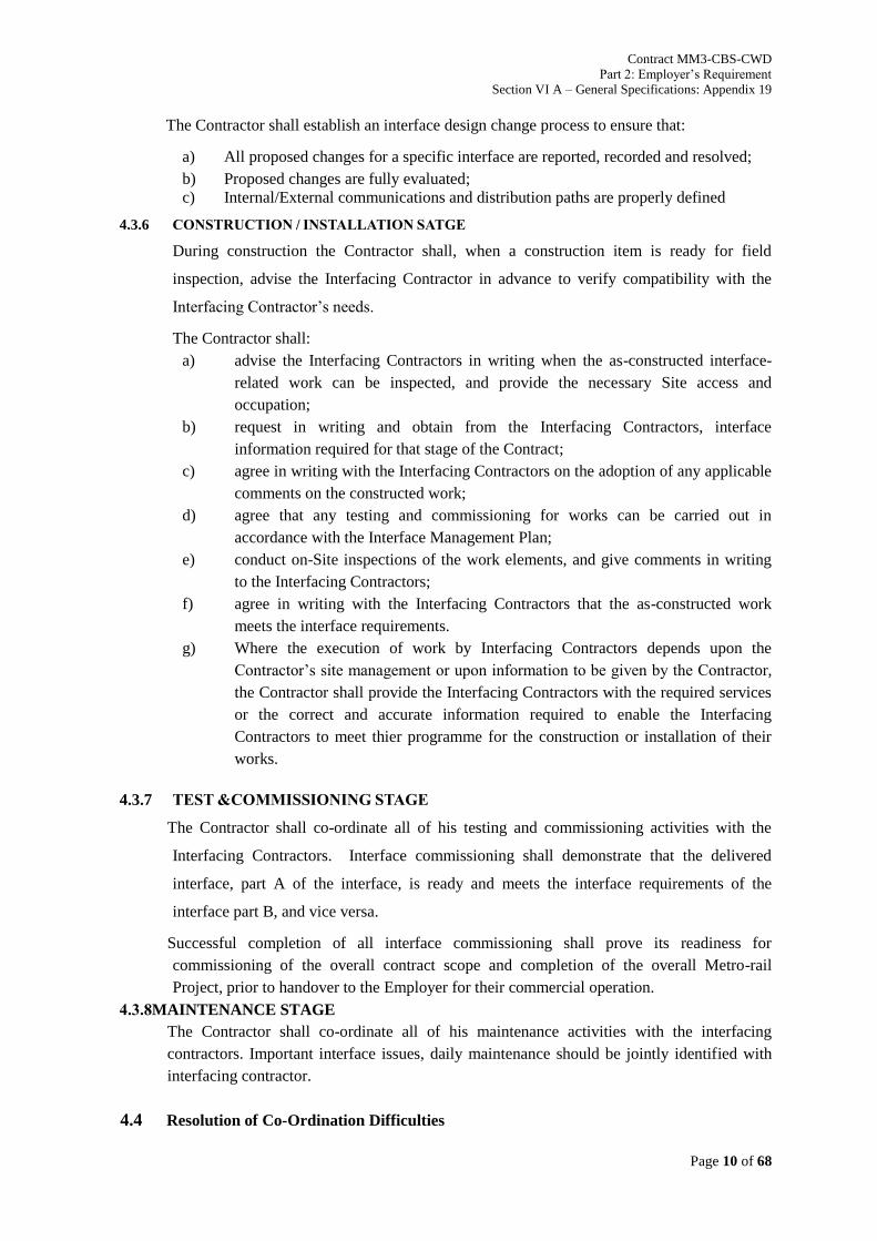
Contract MM3-CBS-CWD
Part 2: Employer’s Requirement
Section VI A – General Specifications: Appendix 19
GCC-MMR-301-P00-160GCC-3 Page 10 of 68
The Contractor shall establish an interface design change process to ensure that:
a) All proposed changes for a specific interface are reported, recorded and resolved;
b) Proposed changes are fully evaluated;
c) Internal/External communications and distribution paths are properly defined
4.3.6 CONSTRUCTION / INSTALLATION SATGE
During construction the Contractor shall, when a construction item is ready for field
inspection, advise the Interfacing Contractor in advance to verify compatibility with the
Interfacing Contractor’s needs.
The Contractor shall:
a) advise the Interfacing Contractors in writing when the as-constructed interface-
related work can be inspected, and provide the necessary Site access and
occupation;
b) request in writing and obtain from the Interfacing Contractors, interface
information required for that stage of the Contract;
c) agree in writing with the Interfacing Contractors on the adoption of any applicable
comments on the constructed work;
d) agree that any testing and commissioning for works can be carried out in
accordance with the Interface Management Plan;
e) conduct on-Site inspections of the work elements, and give comments in writing
to the Interfacing Contractors;
f) agree in writing with the Interfacing Contractors that the as-constructed work
meets the interface requirements.
g) Where the execution of work by Interfacing Contractors depends upon the
Contractor’s site management or upon information to be given by the Contractor,
the Contractor shall provide the Interfacing Contractors with the required services
or the correct and accurate information required to enable the Interfacing
Contractors to meet thier programme for the construction or installation of their
works.
4.3.7 TEST &COMMISSIONING STAGE
The Contractor shall co-ordinate all of his testing and commissioning activities with the
Interfacing Contractors. Interface commissioning shall demonstrate that the delivered
interface, part A of the interface, is ready and meets the interface requirements of the
interface part B, and vice versa.
Successful completion of all interface commissioning shall prove its readiness for
commissioning of the overall contract scope and completion of the overall Metro-rail
Project, prior to handover to the Employer for their commercial operation.
4.3.8MAINTENANCE STAGE
The Contractor shall co-ordinate all of his maintenance activities with the interfacing
contractors. Important interface issues, daily maintenance should be jointly identified with
interfacing contractor.
4.4 Resolution of Co-Ordination Difficulties

Contract MM3-CBS-CWD
Part 2: Employer’s Requirement
Section VI A – General Specifications: Appendix 19
GCC-MMR-301-P00-160GCC-3 Page 11 of 68
When the Contractor identifies interface co-ordination difficulties, the Contractor shall
review the pertinent points of each Interfacing Contractor to determine possible compatible
solutions in terms of sequence, timing and technical details. The Contractor shall then meet
with the relevant Interfacing Contractor(s) to determine solutions, which are mutually
acceptable to each Interfacing Contractor and advise the PM.
Where an acceptable solution has not been identified, the Contractor shall advise the PM in
writing of the problems encountered. If, in the opinion of the PM, an interface is not
proceeding satisfactorily, then the PMwill review the matter, and establish a co-ordinated
plan directing the Contractor and the Interfacing Contractor(s) on the required action. In the
event that no agreement can be made between the Contractor and the Interfacing
Contractor(s), the PMshall determine the requirements to the best of his knowledge, and his
determination shall be final and binding on the Contractor and the Interfacing Contractor(s).
4.5 Interface Performance
The Contractor’s performance in relation to his compliance with the interface requirements
under the Contract shall be assessed by the PMthree months after the Commencement Date
and thereafter at three monthly intervals. The assessment will be in the form of an audit of
the Contractor’s interface management system. This audit will assess the Contractor’s
compliance with the responsibilities delineated in this Appendix 19and elsewhere as related
to interface management and the preparation of the Interface Management Plan (IMP) and
Programme and other documentation and procedures associated with Interface Management
and Coordination.
The Contractor will be notified of non-conformances from the audit, which will require
rectification. Where, in the opinion of the PM, the Contractor has failed to rectify a non-
conformance within a reasonable period from the date of notification, this may lead to non-
payment of any lump sums, until such time as the non-conformance has been rectified to the
satisfaction of the PM, refer sub-clause below.
The Contract allows for continuous audits of the Contractor’s compliance with his Interface
Management Plan and the requirements of this Appendix 19 of Part 2 Employer’s
Requirements, and any extreme or continuing failures shall result in a negative audit report,
which may lead to non-payment of the relevant payment item in the Preliminaries section of
the Pricing Document. The decision of the PMin this regard shall be final.
5. CONTRACTOR’S INTERFACE MANAGEMENT SYSTEM
5.1 Interface Management System
The Contractor shall establish and maintain an Interface Management System to identify,
control and monitor the interfaces of the Contract, which shall include, but not be restricted
to, the following:

Contract MM3-CBS-CWD
Part 2: Employer’s Requirement
Section VI A – General Specifications: Appendix 19
GCC-MMR-301-P00-160GCC-3 Page 12 of 68
a) Establishment and maintenance of an Interface Management Team suitably qualified
and experienced in co-ordination and interface management in relationship with the
GCIM.
b) Provision, as one of his Key Personnel, of a Chief Interface Co-ordinator, to head the
Interface Management Team, suitably qualified and experienced as noted in Section
A of this Part 2 Employer’s Requirements, with the responsibility, experience and
authority to resolve interface matters in accordance with the Contract. The Chief
Interface Co-ordinator (CIC) will develop a monitoring and reporting procedure to be
implemented by his team for the duration of the Contract.
c) Implement and maintain a strict monitored control of information transfer to the
Interfacing Contractors, the Employer and the PMutilising the official channels of
communication.
d) Provide a comprehensive interface schedule of Interfacing Contractors, including
specialist domestic interfaces (i.e. specialist testing and commissioning engineers)
identifying all interfacing activities and timetables of events.
e) Arrange all internal and external interface meetings. The PMmay arrange regular
meetings to monitor the status of interfaces, and may require special meetings asthat
are necessary to resolve specific issues. The Contractor’s Interface Management
Team will be required to attend such meetings. The Contractor may request
assistance from the PM(and GCIM/RE) to arrange meetings on particular subjects.
f) Providing the PM(and GCIM/RE) with all information and/or details of interfaces,
including copies of all correspondence and material.
g) Providing the PM(and GCIM/RE) with access to information for the purpose of
conducting audits on the interface system and for confirming that interface co-
ordination is proceeding consistently with the Project requirements.
h) Establish interface dates for information, documentation, access or works completion
requirements.
5.2 Interface Management Team
The Contractor’s Interface Management Team will undertake and fulfil the following tasks:
a) Provide timely interface information when requested, anticipating the information
needs of the Interfacing Contractors and transmitting such information as soon as it is
available.
b) Pro-actively keep the Interfacing Contractors informed of any development of the
Works related to the interfaces. Communicating and co-operating with the Interfacing
Contractors to identify and resolve potential interface problems.
c) Advise the Interfacing Contractors on potential problems related to the interfaces,
together with proposed solutions likely to be acceptable to Interfacing Contractors
and which meet the needs of the Project.
d) Arrange and/or attend meetings with the Interfacing Contractors as necessary to
resolve interface issues.
e) During each stage of the Contract, the Contractor shall directly communicate and co-
ordinate with Interfacing Contractors as necessary to achieve a fully co-ordinated
construction/installation.

Contract MM3-CBS-CWD
Part 2: Employer’s Requirement
Section VI A – General Specifications: Appendix 19
GCC-MMR-301-P00-160GCC-3 Page 13 of 68
f) Contractor shall issue true records of all interface meetings, with appropriate actions
and attendance lists, to all Interfacing Contractors, whether in attendance or not, and
to the PM(and GCIM/RE), within 3 days of the meeting. Minutes of meetings shall
be signed by all parties in attendance, signifying their agreement to the contents
thereof, before being formally issued by the Contractor.
The authority and responsibilities of all personnel involved in the Interface Management
Team must be clearly defined in the IMP.
6 .INTERFACE MANAGEMENT PLAN & INTERFACEMANAGEMENT PROGRAMME
6.1 General
The Contractor shall prepare the proposed Interface Management Plan and proposed
Interface Management Programme, in accordance with Part 2 Section VI-A clause 3.4, this
clause 6 and based on the formats noted in Attachments H and I, to which the PMissues a
notice of no objection. The Interface Management Plan (IMP) and Interface Management
Programme shall completely define the Contractor’s programme and methodology for
interface co-ordination and management, whilst complying with all Key Dates stated in the
Appendix to Tender and/or Appendix 3of this Part 2 Employer’s Requirements.
Subsequently they shall be kept up to date and submitted on a quarterly basis to the PMfor
scrutiny and notice of no objection, and a summary of the principal issues shall be included
in each Monthly Progress Report. The Contractor shall note that each submission of these
documents is subject to regular audits and the issue of a notice of no objection by the PM.
6.2 Interface Management Programme (IMPG)
The Interface Management Programme describes the sequencing and timing of each of the
Interfacing Contractor’s scope of work, clearly describing the interdependencies for all
stages of the work between the Contractor's works and that of the Interfacing Contractors
and complementing the Interface Management Plan, whilst complying with all Key Dates
stated in the Appendix to Tender and/or Appendix 3of this Part 2 Employer’s Requirements.
The programme shall be structured to detail each of the primary zones of interface and the
principal elements of the design and of the works requiring interfacing contribution from
others. This Interface Management Programme shall also be related to the Contractor’s
Works Programme and shall show the sequences and timing agreed with the Interfacing
Contractors to the necessary degree of detail to clearly illustrate each of the interfaces to be
undertaken.
Targets to receive or supply information shall also be shown, with due allowance being
given for the design process of others. Information relating to Contractual Key Dates and
information exchange dates shall be shown for both the Contractor and the Interfacing
Contractors to demonstrate a matching of design processes.
A record of these interfaces, with current status and agreed dates for information transfer,
site inspections, access, occupation, handover, etc..shall be maintained and also identified on
theICS, refer Clause 7 below.
Refer to Attachment K - Guidance Notes for the Preparation of IMPG
6.3 Interface Management Plan (IMP)

Contract MM3-CBS-CWD
Part 2: Employer’s Requirement
Section VI A – General Specifications: Appendix 19
GCC-MMR-301-P00-160GCC-3 Page 14 of 68
The Interface Management Plan is that document which describes the Contractor’s interface
management in terms of providing a clear description of each of the interfaces, both
technically and sequentially, and represents an account of how the Contractor proposes to
achieve co-ordination of the Works. The description shall completely detail the Contractor's
work scope and interface with each of the Interfacing Contractors in terms of technical
description, sequence and timing for each of the elements required to achieve a coordinated
design. The Contractor shall demonstrate how potential interface conflicts can be eliminated
by design simplification. This document is also required to demonstrate that the co-
ordinated design and construction details described therein fully comply with the needs of
others, and agreement in writing of these details by the Interfacing Contractors will be a pre-
requisite to the PMissuing a notice of no objection. In this step, the IMP shall be submitted
to the PM for approval with this Notice of No Objection.
Refer to Attachment L – Guidance Notes for the Preparation of IMP.
6.4 Requirements For The Interface Management Programme &Interface Management
Plan
The Interface Management Programme (IMPG) shall be a process-driven programme in a
format to be agreed with the PM. The IMPG shall incorporate the key activities from both
the Interfacing Contractors’ and Contractor’s Works programmes that will enable the
Contractor to demonstrate that any Interface is being correctly managed and will result in
fully co-ordinated construction / installation of works.
The Interface Management Plan and Interface Management Programme shall:
a) Follow the outline structure, numbering system, and related procedures in a format to
be agreed with the PM(and GCIM/RE).
b) Be co-ordinated with the Interfacing Contractors to ensure compatibility of interface
identification and definition.
c) Comply with the Key Dates stated in the Appendix to Tender and/or Appendix 3of
this Part 2 Section VI-A Employer’s Requirements.
d) Be transmitted to the Interfacing Contractors concurrently with submittals to the PM.
e) Support the Works Programme to which the PM has given a notice of no-objection.
f) Address each zone of interface i.e. ancillary buildings, train stabling, trackwork
external, trackwork internal, substations, signalling and telecommunications facilities,
operation and control rooms, staff accommodation, external works etc. related to each
design submission and stage of design or construction / installation.
g) List all relevant interfaces in detail, their status, and the corresponding source(s) of
information.
h) Include interface information transfer dates which have been agreed by the Interfacing
Contractors.
i) Accommodate comments and input required by the PM.
j) Include an account of how the interfaces are being managed.
k) Identify the latest information regarding agreements with the Interfacing Contractors
and transfers of information.
l) Review and address the design, supply, installation, testing & commissioning
programme of the Interfacing Contractors to ensure that the Key Dates of each contract
can be achieved, and highlight any programme risks requiring management attention.
m) Identify any problems related to co-ordination with Interfacing Contractors.
6.5 Interface Specification.

Contract MM3-CBS-CWD
Part 2: Employer’s Requirement
Section VI A – General Specifications: Appendix 19
GCC-MMR-301-P00-160GCC-3 Page 15 of 68
6.5.1 The Interface Specification form enclosed in Attachment C, and associated drawings shall
specify the proposed method and schedule for verifying the interface integrity, the individual
equipment/system performance and the combined system performance.
The Interface Specification shall include a programme of tests to demonstrate the
performance and integrity of the integrated system. The interface sheets developed by the
PM(GCIM) are attached inAppendix-19 – Attachment N.Theattached interface sheetsare
not final.They are indicative in natureanddo not relieve the Contractor’s obligation to
identify any new interface to meet contract requirements. The interface sheets, which the
Contractor develops, shall be used as a basis to establish the Interface Specification. Any
revision to the Interface Specification shall be mutually agreed between the Contractor and
Interfacing Contractors, with submission to the PM, and shall specifically -
a) Understand the design requirements of each party and associated constraints;
b) Determine the detailed interface works to be performed during the various stages
and
c) Agree on the interface works in reference to respective scope, with any agreements
reached to be formally documented in InterfaceMinutes of Meetings , including an
actions item list.
6.5.2 The Interface Contractors shall mutually identify and agree the Interfaces that will exist
between them using theInterface Coordination Sheets, the format of which is contained in
AttachmentF part 1. These interfacesshall be expanded, if required, to include all, and any
other, interfaces that develop during the execution of the Project.
6.5.3 The Interfacing Contractors shall mutually agree upon the information to be exchanged and
shall develop a unique Interface Specification for each interface identified. A sample
Interface Specificationproforma is provided in Attachment C.
The ICSs will be tracked and monitored using an ICS Register to be compiled by the
Contractor. This register will track the progress of the ICS from inception through to closure
and final processing by the Contractor, prior to transmittal to the PMas a complete
Integrated Design.
Each interface shall have a unique reference number to enable the Interface to be readily
identified and tracked and monitored.
6.6 Contractor’s Submissions
6.6.1 On commencement of the contract, Master Interface Matrix (MIM) and the Interface
sheets in the Contract Documents shall be used as the reference documents from
which the Contractor develop its Interface Management Plans (IMP) and its
Interface Management Programmes (IMPG). The Contractor has to provide to the PM
the following, as per the due date(s) mentioned below.
a) CV of CIC subject to Notice of No Objection (BDE1) by PM(30 days)
b) Interface Management Plan (IMP) (45 days)
c) Interface Management Programme (IMPG) 3 month rolling program updated monthly
(45 days)
d) Interface Coordination Sheets (ICS) – monthly progress report pertaining to interface
matters (45 days)
e) Confirmation of Coordination form (45 days)
f) Interface specification (45 days)

Contract MM3-CBS-CWD
Part 2: Employer’s Requirement
Section VI A – General Specifications: Appendix 19
GCC-MMR-301-P00-160GCC-3 Page 16 of 68
6.6.2 The PM shall review the Contractor’s interface submissions and issue Notice of No
Objection for those sections that comply with the contractual requirements of Interface
Management and recommend changes to any sections that do not meet Employer’s
Requirements. The Master Interface Log (MIL) is updated by PM/GCIM (IST) with the
sections of the Contractor’s IMPG that receive a Notice of No Objection. A sample Master
Interface Log example is provided in Attachment D.
6.6.3 To receive a Notice of No Objection, the Contractor’s Interface Management Programme
(IMPG) and Interface Management Plan (IMP) shall meet the Employer’s requirements on
Interface Management - Appendix 19 of Part 2 Section VI A.
6.6.4 The PM/GCIMis responsible for the overall implementation and maintenance of the
interface management process throughout the project life cycle by developing and
implementing interface management work processes, capturing the necessary interface
agreements, monitoring progress, ensuring that schedule requirements are maintained and
pointing out any change requests that may arise out of interface requirements.
6.7 Monitoring the Progress of Interface Agreements
6.7.1 The Chief Interface Coordinator (CIC) of the Lead Contractor convenes regular Interface
Meeting with the Interfacing Contractor to progress the Interface issues by keeping track of
activities required to be performed towards facilitating the needed exchange of information.
The Lead Contractor writes the Minutes of Meeting, actions oriented and systematically
review the last Minutes of Meeting to confirm agreement, check progress, prior to examining
new items.
6.7.2 The PM/GCIM (IST TL) and his delegates monitor the status of the interface agreements on
a regular basis by having periodical (weekly or monthly) meetings with the concerned
persons. The Interface Agreements with a `Critical’ rating are prioritized and rigorously
monitored.
6.7.3 When the Interfacing Contractor receives the requested information by the required date and
considers it acceptable, to close a particular interface item/location Lead Contractor will
record in the confirmation of coordination form for the interfacing element and send it to the
Interfacing Contractor/s for agreement. The mutually agreed Interface Specification is then
submitted to PM for Notice of No Objection.
6.7.4 To close a particular significant phase or portion, Lead Contractor will record in the Interface
Specification document and send it to the Interfacing Contractor’s for agreement. The
mutually agreed Interface Specification is then submitted to PM for Notice of No Objection.
If PMraises any objection, the Lead Contractor re-works the Interface Specification
document, in consultation with the Interfacing Contractor, and re-submits to PM for Notice
of No Objection. After issue of Notice of No Objection, the Interface Agreement is recorded
as `closed’ in the Interface Databases of both the Contractors as well as in the MIL. The
closed interfaces are omitted from future interface agreement reporting.
6.7.5 The PM/GCIM shall prepare Status Reports from the Master Interface Log (MIL) on the
progress of the Interface Agreements as part of the Monthly Progress Reports to the
Employer.

Contract MM3-CBS-CWD
Part 2: Employer’s Requirement
Section VI A – General Specifications: Appendix 19
GCC-MMR-301-P00-160GCC-3 Page 17 of 68
6.7.6 PM/GCIM shall check the physical interfaces on site as necessary to make sure that they are
progressing according to the agreements made by the Interfacing Contractors and report to
the PM/GCIM.
7 .INTERFACE COORDINATION SHEET (ICS)
7.1 The Contractor’s Interface Coordination sheet, the format of which is shown in Attachment
F – Part 1, is required to be used by each of the Interfacing Contractors to record all of the
Contract Interfaces. The Contractor shall ensure that each Interfacing Contractor provides
input and maintains the ICS continually updated as required in this Appendix 19 .
7.2 The Contractor shall ensure that the Interfacing Contractors demonstrate their co-ordination
efforts as required by the Contract. To achieve this, the Contractor and the Interfacing
Contractors shall identify their interface requirements which shall be input into the interface
documents i.e. IMP, IMPG, ICS etc. by the Contractor.
7.3 The Contractor shall monitor the ICS to ensure that, as the Interface progresses, the records
show the appropriate Status (refer status codes indicated in Part 3 of Attachment F) as
agreed with the Interfacing Contractors. The Contractor will be responsible for confirming
the “Closing Out” of each ICSrecord, whilst ensuring that throughout the interface process
all Interfacing Contractors have agreed to the following:
a) The receiving Interfacing Contractor has received and accepted the Interface being
recorded.
b) All InterfacingContractors have recorded the interface record as “Proposed Close
Out”.
c) The Confirmation of Co-ordination form in Attachment G has been updated and
signed by the relevant Interfacing Contractors, refer clause 7.4 below.
7.4 When documents are exchanged for review/comment with Interfacing Contractors, the
originator preparing these documents should ensure that they are accompanied by the
Confirmation of Coordination form in Attachment G. When the Interfacing Contractor
returns these documents with comments to the originator, they should be returned with the
Confirmation of Coordination form duly completed, confirming coordination and agreement
or comment as appropriate, as a record of them having coordinated the interface item. This
Confirmation of Co-ordination is to be transmitted to the PM,upon signing by the
Interfacing Contractor(s), for Notice of No Ojection with the appropriate Template
Attachment H- Review and Comment on all Design / Interface Submittals. The Rank ( B,
Ma, Mi ) iscatgoriesd into blocked, major & minor catagories.
7.5 The PM will obtain approval from MMRC on every Main Features of the final designs /
drawings with respect of the following “Approval for Notice of No Objection”.
8. COORDINATION DRAWINGS
8.1 General
For the purpose of achieving a Project which is fully co-ordinated with respect to civil,
structural, architectural, building services, electrical, mechanical works and interface
elements, and to ensure compatibility between different facilities and services, and adequate
space requirements, all drawings are to be reviewed and co-ordinated by the Civil Work
Contractor.

Contract MM3-CBS-CWD
Part 2: Employer’s Requirement
Section VI A – General Specifications: Appendix 19
GCC-MMR-301-P00-160GCC-3 Page 18 of 68
The Civil Work Contractor will provide and issue detailed Interface Working Drawings in
terms of items such as; special arrangements, space allocation, cast in items, primary and
secondary fixings, grouting of equipment/plinths, drill and fix brackets, embedded and cast-
in items and the like.
The drawings shall be prepared by the Civil Work Contractor, reviewed and validated by the
Contractor for its own Interface in accordance with the ICS.. The Civil Work Contractor
shall also include composite cross-sections and layouts, which show the spatial requirements
of all Interfacing Contractors and identify items to be finalised, defined, or resolved.
8.2 Combined Services Drawing (CSDs) And Structural E&M Drawings (SEMs)
The Civil Work Contractor’s CSDs and SEMs must be clear and sufficiently detailed to
unambiguously show the intent of the subject services and the corresponding structure /
facility allowances. While these drawings do not have to duplicate all of the details of the
Drawings, they must include plans sections and elevations as required to clearly illustrate the
compatible relationship between the different disciplines. Specifically, the drawings will
include wall elevation drawings at 1:50 scale (or larger where required) indicating all
openings, access panels, reinforcement zones, embedded and cast-in items and the like, and
shall be submitted to the PMfor a Notice of No Objection.
The CSDs shall show the intended locations, routes and spatial relationships of the
individual E&M services, Building Services systems, and installations, Depot Equipment,
Core Systems installations and other installations, fully co-ordinated with each other and the
civil structural and architectural work. The CSDs shall also clearly indicate that effective
cable co-ordination has been achieved in terms of cable location or cable trays and the
trunking and cable routing.
The SEMs shall show all civil, structural, and architectural requirements for the E&M
services, Building Services systems and installations, Builder’s works and the Core Systems
and other installations.
Where Builder’s works are required by the Interfacing Contractors, the drawings, details,
specification notes and catalogue information and the like shall be obtained by the Civil
Work Contractor from these Interfacing Contractors indicating the builder’s work to be
incorporated into the Works. The Civil Work Contractor shall include details of such
Builder’s works in the SEMs and Method Statements as appropriate.
Builder’s work comprises, but is not limited to, the following:
a) construction of plinths, bases, builders bund walls and the like.
b) placing and fixing of holding down bolts, lifting beams and hooks and other
supporting items;
c) supply, fabrication installation, protection, fixing and finishing of supporting
steelwork, for equipment and associated accessories;
d) casting in of edgings, angles in recesses, ducts, conduit, pipes etc;
e) fixing equipment and associated, brackets, cable containment and fixtures;
f) forming of penetrations, sleeves, access panels, holes, chases, recesses, openings;
all in accordance with the Civil Work Contract.
The CSD/SEMs shall also be used for the purpose of co-ordinating with the Interfacing
Contractors and shall be continuously updated to reflect the latest interface co-ordination.
Copies of the CSD/SEM drawings shall be included in submittals to the PM(and
GCIM/RE).

Contract MM3-CBS-CWD
Part 2: Employer’s Requirement
Section VI A – General Specifications: Appendix 19
GCC-MMR-301-P00-160GCC-3 Page 19 of 68
Where the CSDs or SEMs do not fully co-ordinate with the Site conditions the Civil
CoontractorContractor shall co-ordinate and propose a solution to the problem. All
proposed solutions shall be issued to the PMas Project Manager.
8.3 Interface Drawings
For the Interface Drawings, the Contractor shall prepare in diagrammatic format for each
interface the demarcation of scope of responsibilities between the Contractor and each of the
Interfacing Contractors. The Contractor shall submit all Drawings with interface
requirements for a notice of no objection from the PM. Any proposed deviation to the
Construction Specification or Drawings shall be identified and justified with design
documentation, details and drawings. The submission shall also identify all interface
requirements. The contractor should develop own interface drawings with detailed design
and dimensions and submit the same to other interfacing contractor.
8.4 As Constructed Drawings
Upon completion of the Works the Civil Work Contractor shall submit all Combined
Services Drawings, Structural E&M Drawings, and Interface Demarcation Drawings
showing the final “As Constructed” status of the Works related to these drawings.
9. ATTACHMENTS
Attachment A - Flow Chart for creation / elaboration of Interface Coordination Sheet
Attachment B - Flow Chart for Progress Monitoring of Interface Agreements
Attachment C - Interface Specification Form
Attachment D - Master Interface Log (MIL) – Example
Attachment E - Master Interface Matrix (MIM)
Attachment F Part 1 - Interface Coordination sheet - Example
Attachment F Part 2 - Interface Coordination Sheet – Contract Codes
Attachment F Part 3 - Interface Coordination Sheet – Status Codes
Attachment G - Confirmation of Coordination Form
Attachment H - Review and Comment on all Design / Interface Submittals Template
Attachment K - Guidance Notes for the Preparation of Interface Management Programme.
Attachment L - Guidance Notes for the Preparation of Interface Management Plan.
Attachment M – Interface Sheet (Template)
Attachment N –Indicative Interface Sheet List for Contract MM3-CBS-CWD
N1- Indicative Interface Sheet of Track Works and Depot Civil works station.
N2- Indicative Interface Sheet of Track Works and Depot Civil works.
N3- Indicative Interface Sheet of Depot Civil works and Rolling Stock
N4- Indicative Interface Sheet of OCS and Depot Civil works
N5- Indicative Interface Sheet of Signalling, Train Control, PSD & Telecom & Detailed
Design Consultant

Contract MM3-CBS-CWD
Part 2: Employer’s Requirement
Section VI A – General Specifications: Appendix 19
GCC-MMR-301-P00-160GCC-3 Page 20 of 68
N6- Indicative Interface Sheet of Signalling, Train Control, PSD & Telecom & Depot Civil
works
N7- Indicative Interface Sheet of UG Tunnel (UGC-07) and Depot Civil Works.
N8- Indicative Interface Sheet of Depot Civil Works and Depot E&M.
N9- Indicative Interface Sheet of Depot Civil Works and Pylon termination Contractor
N10- Indicative Interface Sheet of Depot equipment Contractor and Detailed Design
Consultant
N11- Indicative Interface Sheet of Detailed Design Consultant and Depot Civil Works.

Contract MM3-CBS-CWD
Part 2: Employer’s Requirement
Section VI A – General Specifications: Appendix 19
GCC-MMR-301-P00-160GCC-3 Page 21 of 68
Attachment A - Flow Chart for creation / elaboration of Interface Coordination Sheet
From either Interface Sheet/Matrix given
in the Contract or through other sources
Existing
New
Record S&P1
Address
Objection Record S&P1No
Yes
Yes
Record S&P1 No
Yes
Note: All activities in the chain of shaded
boxes are performed by Contractors, duly
overseen by PM/GCIM/RE.
1 = Status and Priority Ref Attachment F Part 3
Interface Identified by ONE
Contractor
New or Revision of Existing?
Interface Coordination Sheet (ICS) created / revised and issued by Chief Interface
Coordinator (CIC) of the Lead Contractor
Create new Revision
ICS containing mutually agreed Interface agreement sent to PM
for Notice of No Objection
Recording in Master Interface Register and reporting status toMMRC periodically by Interface Management team in PM’s organization
Other Party consented to Interface Agreement?
Notice of No Objection issued?
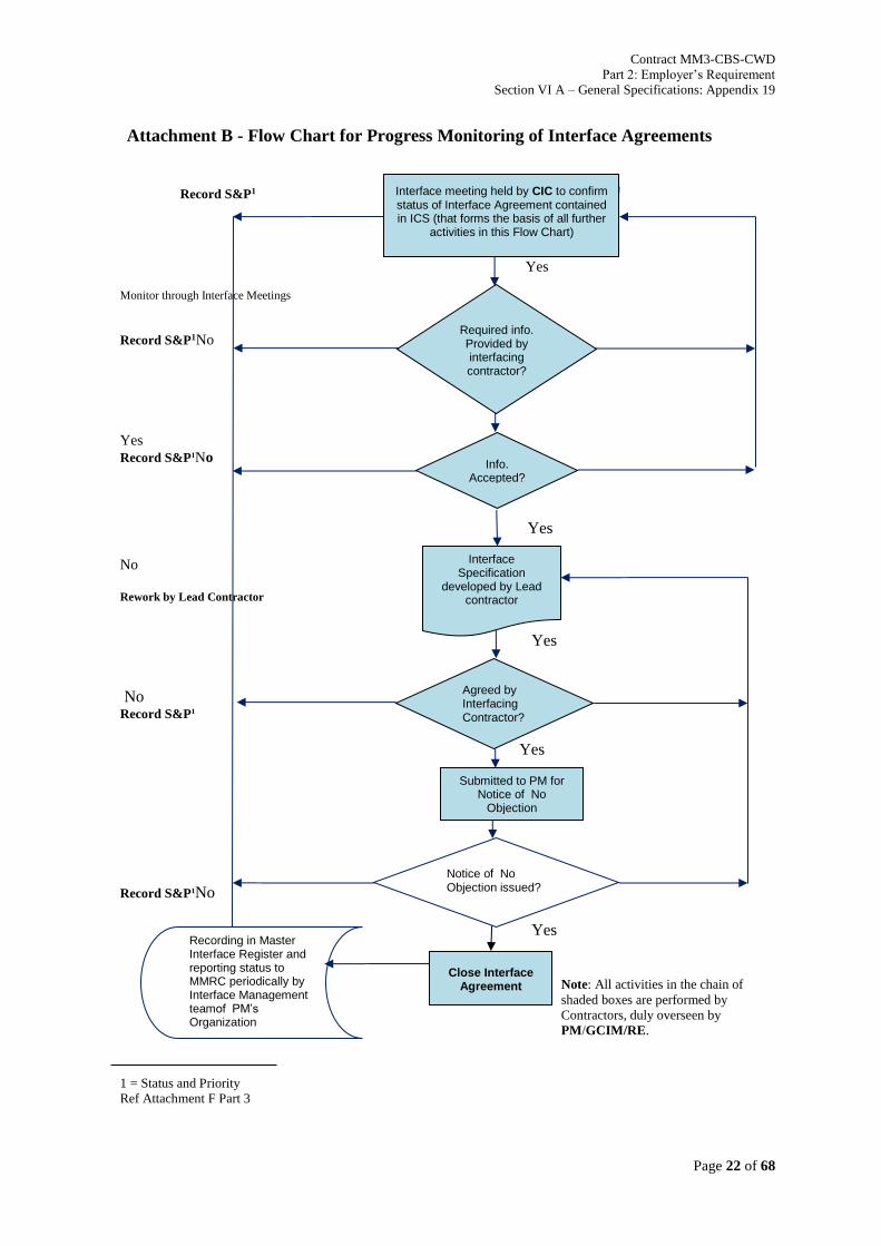
Contract MM3-CBS-CWD
Part 2: Employer’s Requirement
Section VI A – General Specifications: Appendix 19
GCC-MMR-301-P00-160GCC-3 Page 22 of 68
Attachment B - Flow Chart for Progress Monitoring of Interface Agreements
Record S&P1 N
Yes
Monitor through Interface Meetings
Record S&P1No
Yes
Record S&P1No
Yes
No Rework by Lead Contractor
Yes
No Record S&P1
Yes
Yes
Record S&P1No
Yes
Yes
Yes Note: All activities in the chain of
shaded boxes are performed by
Contractors, duly overseen by
PM/GCIM/RE.
1 = Status and Priority
Ref Attachment F Part 3
Interface Specification
developed by Lead contractor
Agreed by Interfacing Contractor?
Submitted to PM for Notice of No
Objection
Close Interface Agreement
Info. Accepted?
Recording in Master Interface Register and reporting status to MMRC periodically by Interface Management teamof PM’s Organization
Required info. Provided by interfacing contractor?
Interface meeting held by CIC to confirm status of Interface Agreement contained in ICS (that forms the basis of all further
activities in this Flow Chart)
Notice of No Objection issued?

Contract MM3-CBS-CWD
Part 2: Employer’s Requirement
Section VI A – General Specifications: Appendix 19
GCC-MMR-301-P00-160GCC-3 Page 23 of 68
Attachment C - Interface Specification Form
INTERFACE
SPECIFICATION Ref: to creat
Contract
Designation
Contractors
Sequence
Number
Date of Issue
Initiating
Contractor
Interface Manager
Signature
Responding
Contractor
Interface Manager
Signature
Interface
Specification
Required for;
Response
Required by;
Reviewed by;
Design Sections
Station Arch. /
Building Services
Description of the Interface
Specific Details of the Interface Location
Drawings / Specifications Attached
Title Drawing / Specification Ref. Drg. Issue
Document Name Date Document References (if any)
Prepared by:

Contract MM3-CBS-CWD
Part 2: Employer’s Requirement
Section VI A – General Specifications: Appendix 19
GCC-MMR-301-P00-160GCC-3 Page 24 of 68
Attachment D - Master Interface Log (MIL) - Example
PM
Ref.
No.
Revision
No.
Interfa
ce Item
No.
Stage Location Contract A Name Contract B Name Status Remark
s
10 A0 UT/US-
05
Construction /
Installation
Mahalaxm
i
Contract UAA-02 shall install
cable containment for HV,
LV, Signal & telecom and
emergency lighting cable
routing
UAA-02 Contract UAA-0 shall
lay power cable for
emergency light and
control cable for
telephone system from
station (controllers will
be from Mumbai
Central station up to
May Day Park shaft)
UAA-01 Pending
10 A0 UT/US-
06
Construction /
Installation
Mahalaxm
i
Contract UAA-02 shall
construct temporary and
permanent drainage system
and interlink with contract
UAA-01 drainage system
UAA-02 Contract UAA-01 shall
construct temporary
and permanent
drainage system and
interlink with contract
UAA-02 drainage
system
UAA-01
10 A0 UT/US-
07
Construction /
Installation
BKC Completion of contract
UAA2-02 handover shaft
back to UAA-01
UAA-02 Contract UAA-01 shall
Jointly inspect and
accept the shaft
handed over by UAA-
02
UAA-01 Completed
10 A0 UT/US-
08
Test &
Commissionin
g
SEEPZ Alignment of the tunnels, 1st
stage concrete in the tunnels
to match with the shaft base
slab
UAA-02 Agree and accept UAA-01 Completed
10 A0 UT/US-
09
Maintenance Santacruz Stop water leakage between
the Shaft wall & tunnels
UAA-02 Joint inspection and
accept
UAA-01 Pending

Contract MM3-CBS-CWD
Part 2: Employer’s Requirement
Section VI A – General Specifications: Appendix 19
GCC-MMR-301-P00-160GCC-3 Page 25 of 68
Attachment E - Master Interface Matrix (MIM)

Contract MM3-CBS-CWD
Part 2: Employer’s Requirement
Section VI A – General Specifications: Appendix 19
GCC-MMR-301-P00-160GCC-3 Page 26 of 68
Attachment F Part 1 - Interface Coordination sheet- Example
Elevated stations contractor A
Interface Co-ordination Sheet:EAS-05 / AC 01
Viaduct Corridor - 1 Contractor B
PROVISIONS AS PER THE INTERFACE SHEET INTERFACE IMPLEMENTATION
NO Project Stage Interface point-Lead Interface Point- Participating Status Action/Progress records &Folllow-ups
Sheet 2 – MMRC Station
2 Design Stage
Contractor A (Lead
Contract) shall furnish the
details of Viaduct
Lighting mast locations
and loading details to Contr
actor-B (Lead Contract)
Contract B(Participating
Contract) shall collect the
loading particulars of
Viaduct lighting mast of
various locations.
Shall design and provide the
details of foundations
Pending
Past Activity
Activity during the Month
1 meeting during the Month
Major Decisions
A. Contract A shall fix cable trays by anchor fasteners
B. Contract A to submit mutually agreeable method
statement
by 15th Dec 2010
Open Issue
3 Design Stage
Contractor-A(Lead
Contract)shall request
fitting/mounting arrangement
s to install cable containme
nt for
signal, telecom and LV &
Lighting cables
Contractor-B(Participating
Contract) shall include in
viaduct design
Pending
Past Activity
3 Minutes of Meeting
Activity during the Month
1 meeting 10th December
Major Decisions
A. Contract A shall fix cable trays by anchor fasteners
B. Contract A to submit mutually agreeable method
Statementby 15th Dec 2010
Open Issue

Contract MM3-CBS-CWD
Part 2: Employer’s Requirement
Section VI A – General Specifications: Appendix 19
GCC-MMR-301-P00-160GCC-3 Page 27 of 68
Attachment F Part 2 - Interface Coordination Sheet-Contract Codes
The following table provides the Interfacing Party Contract codes to be used whenpreparing /
updating the Contractors Interface Coordination Sheet, which should be prepared on thebasis of a
separate Excel spreadsheet for each Interfacing Party.
Interface Party Codes
AFC Automatic Fare Collection
CWD AtGrade Civil Depot& Station
DEM Depot E&M
DEQ Depot Equipment
LET-E Escalator
LET-L Lift
OCS Overhead Contact System
PSS Power Supply System
PYL Pylon Termination
RST Rolling Stock
SSS Station Security System
STPT Signalling ,Train control, PSD and Telecom
TVE Tunnel Ventilation System / Environment Control
System
TWK Track work
UGC Underground Civil (UGC-01 to UGC-07)
Notes :
1 Depot Equipment may be subdivided into individual items of equipment in which case
Contractorswill be notified of designated interfacing codes.
2 Other document coding should be in accordance with the requirements of the Contract and as
agreed with PM.

Contract MM3-CBS-CWD
Part 2: Employer’s Requirement
Section VI A – General Specifications: Appendix 19
GCC-MMR-301-P00-160GCC-3 Page 28 of 68
Attachment F Part 3 - Interface Coordination Sheet- Status Codes
The following table describes the Interface Status with codes to be used in preparing / updating the
Interface Coordination sheet.
Interface Status Codes & Meanings
Interface Status Code for
Log Description of Status
To be coordinated TBC Both Contractor’s have not agreed the conditions for this
interface
Coordinated COR Both Contractor’s have agreed that the interface is valid
Not coordinated NCOR One Contractor does not agree the conditions for this
interface
Received REC The Contractor responsible for the design/construction
element has received the information/documents required
Provided PRO
The Contractor responsible for providing the
information/documents to progress the design/construction
element has provided the documents to the Interfacing Party
Accepted ACP The Contractor has accepted the proposed Interface Design
or Construction element
Not Accepted NACP Either of the Contractors have not accepted the proposed
Design/Construction element
Propose closeout PCO
Both Contractor’s have accepted the proposed Interface
Design or Construction element and no other requirements
are outstanding.
Both Parties can agreed to sign the Confirmation of
Coordination Form
Closed out CO
The final Interface Documentation together with
Confirmation of Coordination Form has been sent to the
Interface Coordination Manager for closing the interface
Superseded SUP The Interface design or construction element has been
superseded

Contract MM3-CBS-CWD
Part 2: Employer’s Requirement
Section VI A – General Specifications: Appendix 19
GCC-MMR-301-P00-160GCC-3 Page 29 of 68
Attachment G – Confirmation of Coordination Form
Mumbai Metro Rail Project
Ref No.
CONFIRMATION OF COORDINATION
CONTRACT: TRANSMITTAL No.:
TITLE:
ACTIVITY NO.:
GENERAL DESCRIPTION:
SIGNATURE OF INTERFACING CONTRACTORS:
Interfacing
Contractor Authorized Name Signature
Date
Reviewed
Comment
1
2
Signatures above confirm that this design document has been reviewed as part of the coordination
process.
NOTE: Where Contractors are not in agreement with the details on this submission, they are to
comment above and advise the interfacing party in question requesting accommodation of the
requirement and advise the PMunder separate cover and report progress in Monthly Report /
Coordination Meetings.

Contract MM3-CBS-CWD
Part 2: Employer’s Requirement
Section VI A – General Specifications: Appendix 19
GCC-MMR-301-P00-160GCC-3 Page 30 of 68
Attachment H-Review and Comment on all Design / Interface Submittals Template
SUBMISSION REVIEW REQUEST No.
SRR of Ref Document
CONTRACT- MM3-CBS-CWD
Column“Commentstatus”contains (Open/closed with date) + Rank(B, Ma ,mi) and is filled in by PM
Interface
Reference No.
Date of
submission
Type of
Reference
Revision:
Subject / Title Date of Review
GC Review Status
Review without objection Review without objection, subject to
Rejected
Reviewer:
Date:
Signature:
Checker:
Date:
Signature:
Column“Commentstatus”contains (Open/closed with date) + Rank(B, Ma ,mi) and is filled in by GC
Page No. /
Paragraph
No.
GC comments Contractor Reply Comment
status
Ranks :
1 B – Blocked
2 Ma – Major
3 Mi – Minor

Contract MM3-CBS-PST-002/2015
Part 2: Employer’s Requirement
Section VI A – General Specifications: Appendix 19
GCC-MMR-301-P00-160GCC-3 Page 31 of 68
Attachment K - Guidance Notes for the Preparation of Interface Management
Programme.
1. The programme shall be prepared and submitted in bar chart format.
2. The bar chart shall be formed by activities grouped by major Zones of Interface.
3. The detail of each bar chart activity shall demonstrate the Contractor’s understanding of the scope
of work of any Interfacing Contractor who is to supply input to the Contractor, in order for him to
achieve an integrated coordinated design.
4. The bars shown on the bar chart shall be annotated with details of the information expected from
the Interfacing Contractors, and highlight any target dates to receive or produce information.
5. Information relating to contractual milestone dates shall be shown on both the Contractor’s and
Interfacing Contractors schedules.
6. The prime purpose of the document is to assist with ensuring that a coordinated design,
construction, testing and commissioning is achieved. This document shall be forwarded to
Interfacing Contractors for comment and agreement on a regular basis.
7. A complementary table of activities and dates should be prepared for ease of reference.
Attachment L - Guidance Notes for the Preparation of Interface Management Plan.
The purpose of this Plan is to demonstrate how the Contractor proposes to achieve a fully coordinated
design, which is compatible with that design carried out by Interfacing Contractors.
This document shall describe each of the component parts, within Zones of Interface, of the design,
which require input from Interfacing Contractors. The descriptions should include details relating to
the inputs required from both the Contractor and Interfacing Contractor, to achieve a fully coordinated
design. The document should also be complementary to the IMPG, which details the proposed
schedule and timings of each of the interfacing activities.
This document shall also detail the proposed interfacing requirements to be met by all Interfacing
Contractors. The Contractor shall ensure that this document is acceptable to the Interfacing
Contractors and that they are able to comply with all of its requirements. This is to be achieved by
document exchanges and discussions to achieve agreement of documents.
The Plan shall therefore:
i) Detail each of the component parts of the Project, which require the input of Interfacing
Contractors to achieve a coordinated design. It shall describe the various disciplines and detail
the technical input from others that will be required to achieve a coordinated design.
ii) Cover the whole duration of the Works and be complementary to the IMPG, which details
the proposed/agreed schedule and timings.
iii) Be given by the Contractor to other Interfacing Contractors for their information and
agreement.
iv) Be developed in association with the process of increasing knowledge of the design and shall
reflect the agreements reached by the Contractor and the Interfacing Contractors as the
Project progresses. The Plan shall be updated on a quarterly basis to reflect this developing
status.

Contract MM3-CBS-PST-002/2015
Part 2: Employer’s Requirement
Section VI A – General Specifications: Appendix 19
GCC-MMR-301-P00-160GCC-3 Page 32 of 68
The Status of any interface at any point in time shall be identified by one of the following conditions;
(i) to be coordinated
(ii) coordinated
(iii) not coordinated
(iv) received
(v) provided
(vi) accepted
(vii) not accepted
(viii) propose close-out
(ix) superseded
(x) closed out

Contract MM3-CBS-CWD
Part 2 - Employer’s Requirement
Section VI. Appendix 19
Page 33 of 68
Attachment M–Interface Sheet (Template)
Mumbai Metro Interface Sheet Contract A
(Lead Contract) Name of Contract
Contract
B(Participating
Contract)
Name of
Contract Sheet # :
Number/max
Rev : A1
Date :
Approved by : ((name(s) and
signature(s))
Discipline A Discipline B Last changes :
PM issued by : Name of writer, position, signature for discipline A Name of writer, position, signature for discipline
B
PM Checked by : Name of checker, DCL, signature for discipline A Name of checker, DCL, signature for discipline B
Interface description brief / Key elements (time schedule, physical, functional,…):
Contract A(Lead Contract) DESIGN STAGE Contract B(Participating Contract)
Title
Interface A Name/Interface B-Number: detail
Interface A Name/Interface B-Number=Number+1: detail
Title
Interface A Name/Interface B-Number: detail
Interface A Name/Interface B-Number=Number+1: detail
Reference documents: Reference documents:
Contract A(Lead Contract) CONSTRUCTION / INSTALLATION STAGE Contract B(Participating Contract)
Interface A Name/Interface B-Number=Number+1: detail Interface A Name/Interface B-Number=Number+1: detai
Reference documents: Reference documents:
Contract A(Lead Contract) TEST & COMMISIONNING STAGE Contract B(Participating Contract)
Interface A Name/Interface B-Number=Number+1: detail Interface A Name/Interface B-Number=Number+1: detail
Reference documents: Reference documents :
Contract A(Lead Contract) MAINTENANCE STAGE Contract B(Participating Contract)
Interface A Name/Interface B-Number=Number+1: detail Interface A Name/Interface B-Number=Number+1: detail
Reference documents: Reference documents :

Contract MM3-CBS-CWD
Part 2 - Employer’s Requirement
Section VI. Appendix 19
Page 34 of 68
Attachment N –Indicative Interface Sheet List for Contract MML3-CBS-CWD
Sr. No. DESCRIPTION
N1 Indicative Interface Sheet of Track Works and Depot Civil works station.
N2 Indicative Interface Sheet of Track Works and Depot Civil works.
N3 Indicative Interface Sheet of Depot Civil works and Rolling Stock
N4 Indicative Interface Sheet of OCS and Depot Civil works
N5 Indicative Interface Sheet of Signalling, Train Control, PSD & Telecom & Detailed Design Consultant
N6 Indicative Interface Sheet of Signalling, Train Control, PSD & Telecom & Depot Civil works
N7 Indicative Interface Sheet of UG Tunnel (UGC-07) and Depot Civil Works.
N8 Indicative Interface Sheet of Depot Civil Works and Depot E&M.
N9 Indicative Interface Sheet of Depot Civil Works and Pylon termination Contractor
N10 Indicative Interface Sheet of Depot equipment Contractor and Detailed Design Consultant
N11 Indicative Interface Sheet of Detailed Design Consultant and Depot Civil Works.
Note- The ”Design stage “ Interface mentioned in Interface Sheets no. N1 to N8 are only for information of the depot civil contractor.The design
part mention in interface sheets will be performed by the DDC civil employed by the employer. The DDC civil contractor will be
responsible to confirm site check.

Contract MM3-CBS-CWD
Part 2 - Employer’s Requirement
Section VI. Appendix 19
Page 35 of 68
N1. INDICATIVE INTERFACE SHEET OF TRACK WORKS(TWK) and DEPOT CIVIL WORKS STATION (CWD)
Mumbai Metro Interface Sheet Contract A TWK Contract B CWD Rev # : A1
Date: 09/01/17
Approved by :
TWK (Track Works)
Lead Contract
CWD (Depot Civil Works station)
Participating Contract
First issue:
GC issued by :
Checked by :
Interface description brief / Key elements (time schedule, physical, functional, ...) :
1.General Interface details between the TWK (Track Works)vs CWD (Civil work depot station)
Contract A(TWK) DESIGN STAGE Contract B(CWD-DDC)
TWK/CWD-01: Shall fix chainages of the turnouts / crossover based on the
chainage of station centre line furnished by the station building
contract.
TWK/CWD-01: Shall furnish correct chainage of station centre line.
TWK/CWD-02: Shall provide the rail level
TWK/CWD-02: Shall Check the rail level.
TWK/CWD-03: Shall check the same.
TWK/CWD-03: Shall ensure that pillars / columns supporting in station
structure are located clear of the minimum infringement
clearance from centre of track stipulated in the S.O.D.

Contract MM3-CBS-CWD
Part 2 - Employer’s Requirement
Section VI. Appendix 19
Page 36 of 68
Mumbai Metro Interface Sheet Contract A TWK Contract B CWD Rev # : A1
Date: 09/01/17
wherever such pillars / column are beyond the platform
length.
TWK/CWD-04: Shall provide track drainage consistent with the general
drainage arrangement in station area.
TWK/CWD-04: Shall design the general drainage system in the station area
taking into account track drainage catchment area.
TWK/CWD-05: Contract B shall verify with contract A.
TWK/CWD-05: Contract A shall ensure that all components of the structure at
intersection with ramp/ At Grade are clear of the structure
gauge of the S.O.D. with respect to the project rail level.
Contract A(TWK) CONSTRUCTION / INSTALLATION STAGE Contract B(CWD)
TWK/CWD-06: Shall jointly check before taking over.
TWK/CWD-06: Shall hand over the track installation area in the vicinity of
pillars / columns and such obstructions clear of the
infringement distances stipulated in the S.O.D.
TWK/CWD-07: Shall ensure proper drainage compatible to Civil Contract
design of drainage.
TWK/CWD-07: Shall furnish levels and location of the general drainage
system in the station area and ensure track drainage is
compatible with general drainage system.
TWK/CWD-08: Track work contract shall jointly decide the storage space and
access for track work as per key Dates of access.
TWK/CWD-08: Shall provide storage space for track materials in
consultation with track contract and shall permit access to
track contract for construction of track as per agreed
schedule of access periods.
TWK/CWD -09: Track contract shall furnish requirement of temporary water
supply. But for track construction work the water supply and
electricity will be arranged by track contract.
TWK/CWD-09: Shall provide temporary water for construction of track on
term of mutual agreement to design & construct the water
supply scheme in consultation with track contract.

Contract MM3-CBS-CWD
Part 2 - Employer’s Requirement
Section VI. Appendix 19
Page 37 of 68
Mumbai Metro Interface Sheet Contract A TWK Contract B CWD Rev # : A1
Date: 09/01/17
TWK/CWD 10: Shall provide survey Data of Track for completion (level and
horizontal) of platform
TWK/CWD 10: level completes the platform (level and horizontal) according
to track.
Reference documents: Reference documents:
Contract A(TWK) TEST & COMMISSIONING STAGE Contract B(CWD)
NIL NIL
Reference documents :
Reference documents:
Contract A(TWK) MAINTENANCE STAGE Contract B(CWD)
NIL NIL
Reference documents: Reference documents:
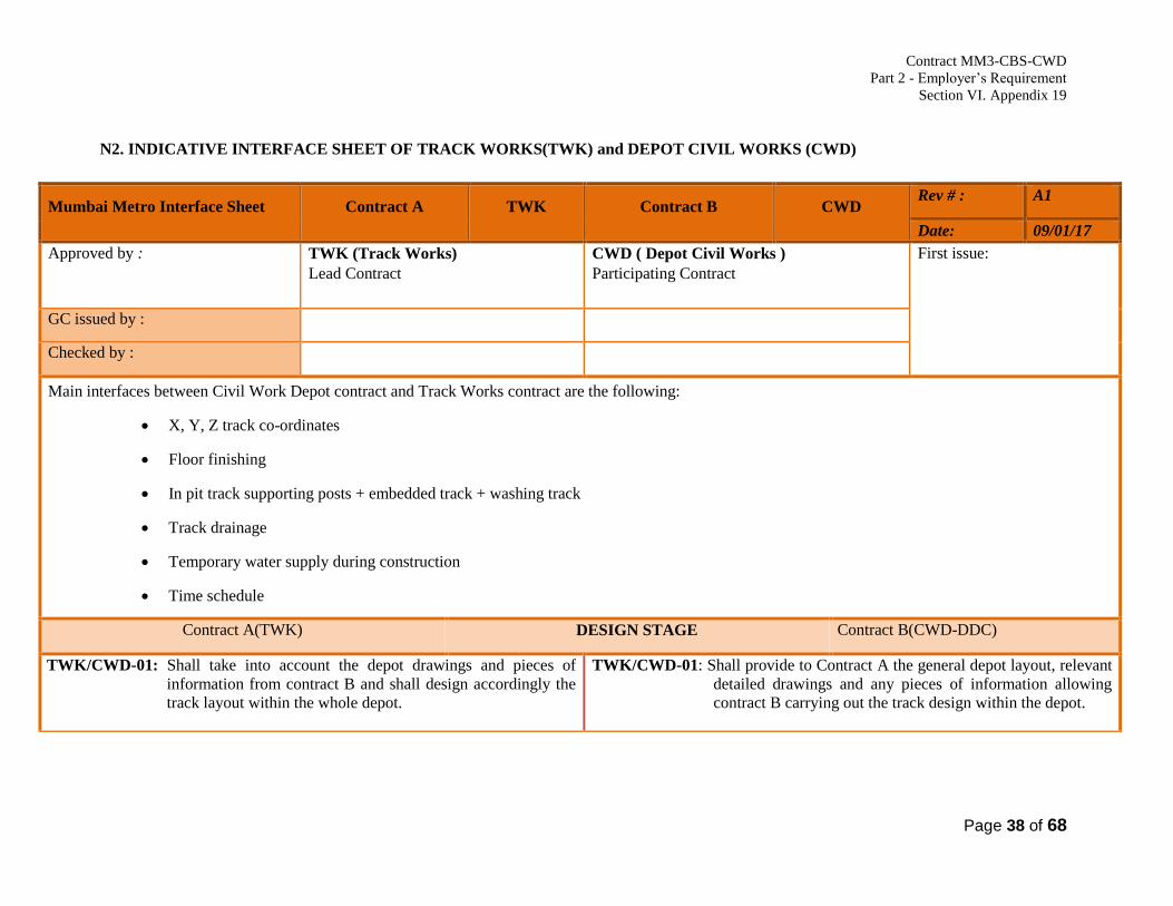
Contract MM3-CBS-CWD
Part 2 - Employer’s Requirement
Section VI. Appendix 19
Page 38 of 68
N2. INDICATIVE INTERFACE SHEET OF TRACK WORKS(TWK) and DEPOT CIVIL WORKS (CWD)
Mumbai Metro Interface Sheet Contract A TWK Contract B CWD Rev # : A1
Date: 09/01/17
Approved by :
TWK (Track Works)
Lead Contract
CWD ( Depot Civil Works )
Participating Contract
First issue:
GC issued by :
Checked by :
Main interfaces between Civil Work Depot contract and Track Works contract are the following:
X, Y, Z track co-ordinates
Floor finishing
In pit track supporting posts + embedded track + washing track
Track drainage
Temporary water supply during construction
Time schedule
Contract A(TWK) DESIGN STAGE Contract B(CWD-DDC)
TWK/CWD-01: Shall take into account the depot drawings and pieces of
information from contract B and shall design accordingly the
track layout within the whole depot.
TWK/CWD-01: Shall provide to Contract A the general depot layout, relevant
detailed drawings and any pieces of information allowing
contract B carrying out the track design within the depot.

Contract MM3-CBS-CWD
Part 2 - Employer’s Requirement
Section VI. Appendix 19
Page 39 of 68
Mumbai Metro Interface Sheet Contract A TWK Contract B CWD Rev # : A1
Date: 09/01/17
TWK/CWD-02: Shall provide to contract B the track depot layout, the
drawings of the different types of track laying (outdoor,
indoor, on pit, in the washing shed etc.), and principles for
track drainage, compacted soil requirements etc., and any
track requirements.
TWK/CWD-02: Shall take into account track drawings, track requirements,
track drainage principles, compacted soil requirements ,pit
drawings, including washable apron etc. from contract A for
designing the depot.The design of the general drainage
system for the depot, including the final formation levels,
gradients, cross slopes, longitudinal cross drainage pipes
culverts crossings. Etc. shall be decided by contract B in
consultation with contract A.
TWK/CWD-03: Shall co-ordinate with contract B, shall furnish any track
updates, shall take into account observations from Contactor
B and shall update the changes, if needed.
TWK/CWD-03: Shall co-ordinate with contract A, shall furnish any depot
updates, shall take into account observations from Contactor
A and shall update the changes, if needed.
Contract A(TWK) CONSTRUCTION / INSTALLATION STAGE Contract B(CWD)
TWK/CWD-04: Shall plan and co-ordinate the track works in the depot with
the progress of depot works based on mutually accepted
programme of works.
TWK/CWD-04(A)Shall ensure with contract B for gaining access to various
location of in depot for executing track work and also for
storing the required track material.
TWK/CWD-04: Shall plan and co-ordinate the depot works with the
progress of track works in the depot based on mutually
accepted programmed of works and ensure key dates for
access.
TWK/CWD-04(A) Shall provide suitable roads for gaining access to various
location of in depot for executing track work and also for
storing the required track materials.

Contract MM3-CBS-CWD
Part 2 - Employer’s Requirement
Section VI. Appendix 19
Page 40 of 68
Mumbai Metro Interface Sheet Contract A TWK Contract B CWD Rev # : A1
Date: 09/01/17
TWK/CWD-05: Contract A shall ensure in respect of track in locations like
washing lines, inspection bay, working lines, etc. contract A shall
check and ensure the concrete base to the required levels
providing suitably dowels for track base plates, shear connectors,
etc. as required before taking over from contract B for installing
the track work.
TWK/CWD-05(A): Before commencing the ballasted/slab track work in an
area, contactor A shall verify with contract B that the
longitudinal and cross drains are completed in that area. Before
laying the track, contract B shall provide designed cross slopes
on the track formation.
TWK/CWD-05: In respect of track in locations like washing lines, inspection
bay, working lines, etc. contract B shall complete the
concrete base to the required levels providing suitably
dowels for track base plates, shear connectors, etc. as
required.
TWK/CWD-05(A): Before handing over the finished formation of depot to
contract A for installing slab/ballasted track, contract B shall
construct and complete the longitudinal and cross drains
forming the drainage network designed by him including up
to out flow and any sump etc Contactor B shall excavate the
finished formation to the required dimensions and install the
drains to proper design levels and with appropriate
perforated drain cover on top for entire drainage.
TWK/CWD-06: Contract A shall request temporary water supply from contract
B, However contract A shall make own arrangement of water
supply for concreting.
TWK/CWD-06: Shall provide temporary water supply during the track
works
TWK/CWD -07: Shall conduct tests and commissioning of track works..
TWK/CWD-07: Shall provide necessary support to contract A to ensure
testing and commissioning of track works..
Reference documents:
Reference documents:

Contract MM3-CBS-CWD
Part 2 - Employer’s Requirement
Section VI. Appendix 19
Page 41 of 68
Mumbai Metro Interface Sheet Contract A TWK Contract B CWD Rev # : A1
Date: 09/01/17
Contract A(TWK) TEST & COMMISSIONING STAGE Contract B(CWD)
TWK/CWD-08:Shall conduct tests and commissioning of track works. TWK/CWD-08: Shall provide necessary support to Contractor a to ensure
testing and commissioning of track works.
Reference documents :
Reference documents:
Contract A(TWK) MAINTENANCE STAGE Contract B(CWD)
NIL NIL
Reference documents: Reference documents:
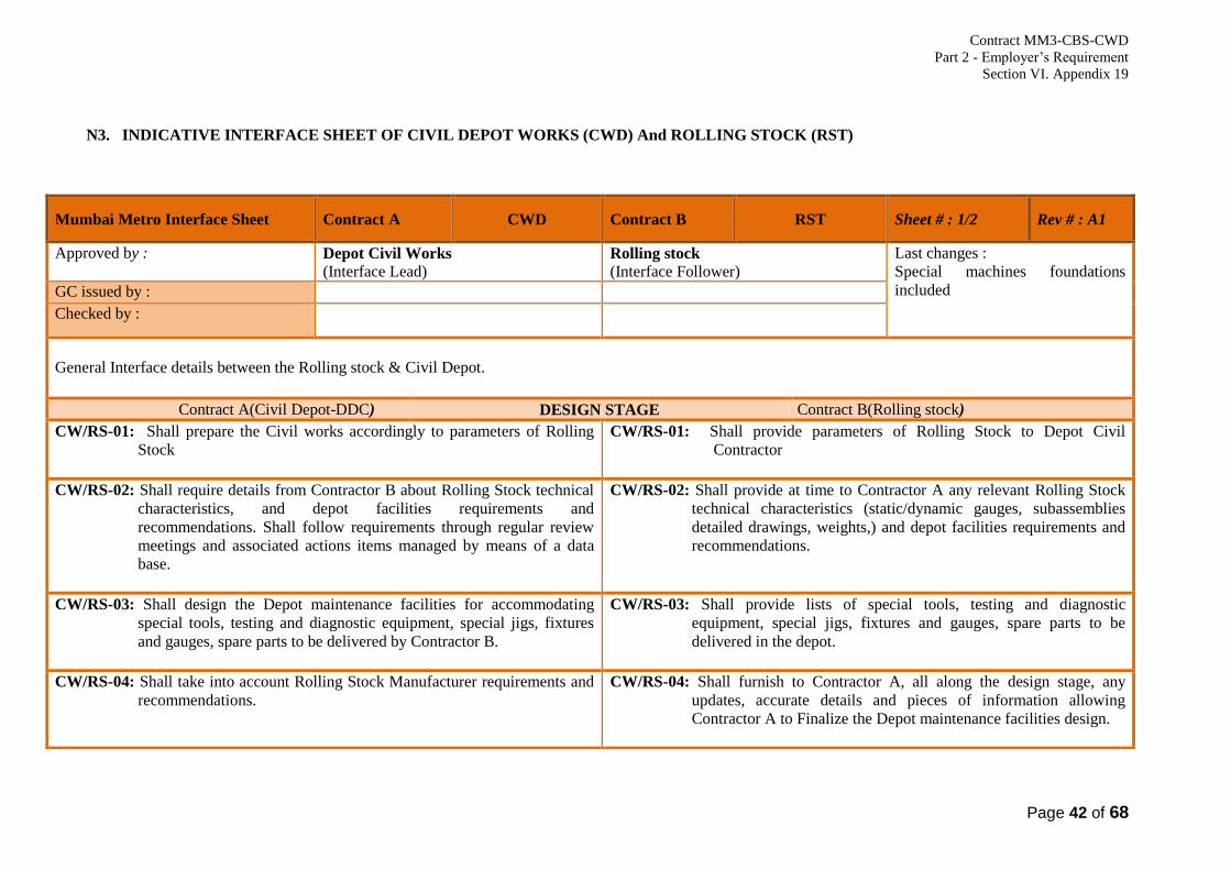
Contract MM3-CBS-CWD
Part 2 - Employer’s Requirement
Section VI. Appendix 19
Page 42 of 68
N3. INDICATIVE INTERFACE SHEET OF CIVIL DEPOT WORKS (CWD) And ROLLING STOCK (RST)
Mumbai Metro Interface Sheet Contract A CWD Contract B RST Sheet # : 1/2 Rev # : A1
Approved by : Depot Civil Works
(Interface Lead) Rolling stock
(Interface Follower)
Last changes :
Special machines foundations
included
GC issued by :
Checked by :
General Interface details between the Rolling stock & Civil Depot.
Contract A(Civil Depot-DDC) DESIGN STAGE Contract B(Rolling stock)
CW/RS-01: Shall prepare the Civil works accordingly to parameters of Rolling
Stock
CW/RS-01: Shall provide parameters of Rolling Stock to Depot Civil
Contractor
CW/RS-02: Shall require details from Contractor B about Rolling Stock technical
characteristics, and depot facilities requirements and
recommendations. Shall follow requirements through regular review
meetings and associated actions items managed by means of a data
base.
CW/RS-02: Shall provide at time to Contractor A any relevant Rolling Stock
technical characteristics (static/dynamic gauges, subassemblies
detailed drawings, weights,) and depot facilities requirements and
recommendations.
CW/RS-03: Shall design the Depot maintenance facilities for accommodating
special tools, testing and diagnostic equipment, special jigs, fixtures
and gauges, spare parts to be delivered by Contractor B.
CW/RS-03: Shall provide lists of special tools, testing and diagnostic
equipment, special jigs, fixtures and gauges, spare parts to be
delivered in the depot.
CW/RS-04: Shall take into account Rolling Stock Manufacturer requirements and
recommendations.
CW/RS-04: Shall furnish to Contractor A, all along the design stage, any
updates, accurate details and pieces of information allowing
Contractor A to Finalize the Depot maintenance facilities design.

Contract MM3-CBS-CWD
Part 2 - Employer’s Requirement
Section VI. Appendix 19
Page 43 of 68
CW/RS-05: Shall design the Depot maintenance facilities to suit Rolling Stock
Manufacturer requirements and recommendations.
CW/RS-05A: Shall design and provide Base foundation and pedestal, Electrical
power required for special machines installation
CW/RS-05: Shall help to contract-A to ensure that Depot maintenance facilities
design fit Rolling Stock requirements and recommendations.
CW/RS-05A: Shall provide details of Base foundation and pedestal, Electrical
power required for special purpose machines installation for those
machines supplied by contractor-B
CW/RS-06:Structure Gauge and Dynamic Envelope (KE) - To ensure Civil
Constructions are as per the SOD.
CW/RS-06: Rolling Stock shall ensure compliance as per stipulations of
Contract and SOD in respect of Static gauge, KE, Structure gauge
and other clearances.
CW/RS-07:Building and Foundation work for Driving Simulator and its
components -Shall prepare the civil works accordingly.
Shall do the foundation work as per the design & drawing.
CW/RS-07: Supply General Arrangement drawing of the Simulator room,
other facilities required. Supply of detailed interface drawings
including detail foundations, showing load points and other Civil
works, etc. Supply of any special grouting material that goes into
foundation.
CW/RS-08: Finishing requirements for Simulator room. - Shall provide
finishing as per the requirements CW/RS-08:Shall provide details of roof, floor and room finishes; Furnish
equipments layouts within the rooms
Reference documents: Reference documents:
Contract A(Civil Depot) CONSTRUCTION / INSTALLATION STAGE Contract B(Rolling stock)
CW/RS-05: Shall ensure conformance to design parameters during Depot
Maintenance facilities construction.
CW/RS-05: Shall co-ordinate with contract-A
CW/RS-06: Shall inform Contractor B with any Depot maintenance facilities
Evolution and updating. Shall find an agreement with Contractor B for
the resolution of any Design change.
CW/RS-06A:Shall provide base foundation and electrical power cable and
compressed air line required for special purpose machine installation
CW/RS-06: Shall inform Contractor A with any Rolling Stock requirements
and Recommendations updating. Shall find an agreement with
Contractor A for the resolution of any design change
CW/RS-06A:Shall install special purpose machines

Contract MM3-CBS-CWD
Part 2 - Employer’s Requirement
Section VI. Appendix 19
Page 44 of 68
Reference documents:
Reference documents:
Contract A(Civil Depot) TEST & COMMISIONNING STAGE Contract B(Rolling stock)
CW/RS-07: Shall conduct tests demonstrating that Depot maintenance facilities
suit Rolling Stock needs.
CW/RS-07: Shall provide necessary support to Contractor A during Depot
maintenance facilities tests and commissioning.
Reference documents :
Reference documents:
Contract A(Civil Depot) MAINTENANCE STAGE Contract B(Rolling stock)
NIL
NIL
Reference documents:
Reference documents:

Contract MM3-CBS-CWD
Part 2 - Employer’s Requirement
Section VI. Appendix 19
Page 45 of 68
N4. INDICATIVE INTERFACE SHEET OF OVERHEAD CONTACT SYSTEM (OCS) and DEPOT CIVIL WORKS (CWD)
Mumbai Metro Interface Sheet Contract A OCS Contract B CWD Rev # : A1
Date: 10/01/17
Approved by :
OCS ( Overhead Contact System )
Lead Contract
Depot Civil Works
Participating Contract
First issue:
GC issued by :
Checked by :
Interface description brief / Key elements (time schedule, physical, functional, ...) :
1.General Interface details between the Overhead Contact System (OCS) vs Depot Civil
Contract A(OCS) DESIGN STAGE Contract B(Depot Civil-DDC)
OCS/Depot-01: Shall provide the locations and load details of Drop Arms with
fixing arrangement for OCS support in Sheds.
OCS/Depot-01: Shall design the Shed structures in depot considering the
requirements of Contract A.
OCS/Depot-02: Shall provide location and load for anchoring of OCS tension lengths
in wheel lathe and workshop sheds.
OCS/Depot-02: Shall design the shed structures and keep provision for holes for
fixing arrangement as per the requirements of Contract A.
OCS/Depot-03: Shall provide the requirements of Duct banks for 33 kV Cables, 25
KV Cables, Traction Return Cables, Control Cables, and BEC in at
grade section to Contract B.
OCS/Depot-03: Shall design the combined services drawings for at grade section
considering the requirements of Contract A.

Contract MM3-CBS-CWD
Part 2 - Employer’s Requirement
Section VI. Appendix 19
Page 46 of 68
Mumbai Metro Interface Sheet Contract A OCS Contract B CWD Rev # : A1
Date: 10/01/17
OCS/Depot-04: Shall provide the requirements of Duct banks for 25 KV Cables,
Traction Return Cables, Control Cables and BEC in Depot to
Contract B.
OCS/Depot-04: Shall design the combined services drawings for Depot considering
the requirements of Contract A.
OCS/Depot-05: Shall design safety interlocking system between Retractable Rigid
OCS and Inspection Bay platform access doors.
OCS/Depot-05: Shall provide details of Access Door of Inspection Bay Platform.
OCS/Depot-06: Shall design safety interlocking system between flexible OCS and
heavy washing shed platform access door. OCS/Depot-06: Shall provide details of Access Door of washing shed platform
Reference documents: Reference documents:
Contract A(OCS) CONSTRUCTION / INSTALLATION STAGE Contract B(Depot Civil)
OCS/Depot-07: Shall install fixing arrangements for Retractable OCS in inspection
bay structural columns.
OCS/Depot-07: Shall drill holes for fixing Retractable OCS in inspection bay
structural columns as per the requirements of Contract-A.
OCS/Depot-08: Shall Install OCS drop arms in heavy washing shed.
OCS/Depot-08: Shall provide vertical steel supports with suitable fastenrs for
fixing OCS drop arms in heavy washing shed.
OCS/Depot-09: Shall supply and install 33 kV cables, 25 KV cables, traction return OCS/Depot-09: Shall provide ductbanks / conduits for 33 kV cables, 25 KV cables,
traction return cables, control cables, and BEC cables in at grade

Contract MM3-CBS-CWD
Part 2 - Employer’s Requirement
Section VI. Appendix 19
Page 47 of 68
Mumbai Metro Interface Sheet Contract A OCS Contract B CWD Rev # : A1
Date: 10/01/17
cables, control cables, and BEC cables in at grade section.
section.
OCS/Depot-10: Shall supply and install 25 KV cables, traction return cables, control
cables, and BEC cables in Depot.
OCS/Depot-10: Shall provide ductbanks / conduits for 25 KV cables, traction
return cables, control cables, and BEC cables in Depot.
OCS/Depot-11: Shall provide a safety interlocking arrangement between the OCS
and inspection bay and heavy washing shed platform access doors.
OCS/Depot-11: Shall install the interlocking arrangement in inspection bay and
heavy washing shed platform access doors.
OCS/Depot-12: Shall Install anchoring plates in wheel lathe and workshop sheds. OCS/Depot-12: Shall provide fixing points for anchoring plates.
Reference documents: Reference documents:
Contract A(OCS) TEST & COMMISSIONING STAGE Contract B(Depot Civil)
OCS/Depot-13: Shall test the interlocking arrangement of inspection bay and heavy
washing shed platform access door with Contract B. OCS/Depot-13: Shall witness the testing of interlocking arrangement for inspection
bay and heavy washing shed platform access door.
Reference documents :
Reference documents:

Contract MM3-CBS-CWD
Part 2 - Employer’s Requirement
Section VI. Appendix 19
Page 48 of 68
Mumbai Metro Interface Sheet Contract A OCS Contract B CWD Rev # : A1
Date: 10/01/17
Contract A(OCS) MAINTENANCE STAGE Contract B(Depot Civil)
NIL NIL
Reference documents: Reference documents:

Contract MM3-CBS-CWD
Part 2 - Employer’s Requirement
Section VI. Appendix 19
Page 49 of 68
N5 . INDICATIVE INTERFACE SHEET OF SIGNALLING, TRAIN CONTROL, PSD & TELECOMMUNICATION (STPT) & DETAILED DESIGN
CONSULTANT(DDC)
Mumbai Metro Interface Sheet Contract A STPT Contract B DDC Rev # : A1
Date: 06/02/2017
Approved by :
ST (Signalling Train Control, PSD &Telecommunication)
Lead Contract
DDC (Detailed Design Consultant)
Participating Contract
First issue:
GC issued by :
Checked by :
Interface description brief / Key elements (time schedule, physical, functional, ...) :
1.General Interface details between the Signalling Train control, PSD & Telecommunication vs. Detailed Design Consultant (DDC)
Contract A(Signalling Train Control, PSD &
Telecommunication)
DESIGN STAGE Contract B (DDC)
ST/DDC-01: a) Shall furnish detailed requirements (space, doors, mechanical load,
lighting, false flooring, cable raceways (routing), Embedded
conduits, vertical risers, cutouts, slab openings, air conditioning &
ventilation arrangements, for etc.) for concerned rooms.
a) Shall furnish the design details of radio masts on buildings,
area and arrangement of fixtures, routing requirements for
antenna cable, aviation warning lights and Earthing
arrangements of the mast. Shall also check the adequacy of
maintenance access for the radio mast, antenna etc
b) shall furnish detailed drawings and load requirements of PSD
at Aarey station Platform
ST/DDC-01: a) Shall integrate S&T detailed requirements and shall provide
detailed design drawings of concerned rooms.
b) Shall check the mast design details from the angle of structural safety
including its fixtures in the structural design and also integrate cable
routing arrangements for antenna cables, aviation warning lights and
Earthing arrangements in the structural design. Plan for adequate
maintenance access for radio mast, antenna etc.
c) Shall incorporate in civil design

Contract MM3-CBS-CWD
Part 2 - Employer’s Requirement
Section VI. Appendix 19
Page 50 of 68
ST/DDC-02: a) Shall integrate the requirements of contractor B in the design of
access control and intrusion detection system.
b) Shall provide the details of fixture for ACID to DDC
ST/DDC-02: a) Shall advise the access control and intrusion detection
requirement, as well as monitoring requirements, for various
locations in the OCC, Aarey station, DCC, Depot perimeter fence
and gate sensors and for access control vehicle barrier. Shall design
the doors so as to be suitable for access control system.
b) Shall incorporate in design the fixture details in the drawings.
ST/DDC-03 Shall furnish the detailed drawings and requirements (dimensions,
cable weight, cable minimum bending radius, cable supporting and
mounting details) of cable routing arrangements and containments.
ST/DDC-03: Shall incorporate all cable routings in combined services drawings
and shall design the cable routing and containments within the yard,
buildings and sheds.
ST/DDC-04: Shall provide detailed drawings and requirements with the locations,
loads, type of fixing / mounting arrangements, etc. of all heavy S & T
equipment like CCTV cameras, TDS clocks, PA speakers, CCTV
monitors, etc. to be installed in concerned rooms and areas.
ST/DDC-04: Shall validate the locations and fixing arrangements in structural and
detailed design.
ST/DDC-05: Shall furnish the requirements of lightning protection for different
S&T systems to be installed
ST/DDC-05: Shall validate the location and installing procedure of lightning
protection system.
ST/DDC-06: a) Shall Design the power cable requirement from OCC S&T UPS
room to CER, OCC, DCC and all depot area.
b) Shall design the S&T power cable requirement from Aarey station
S&T UPS rooms to SER, TER SCR, and station area.
ST/DDC-06: a) Shall co-ordinate with contractor A to finalise the route for the
power cable from UPS room to CER, OCC, DCC and all Depot
area.
b) The same as above for S&T power cable route from Aarey station
(S&T UPS room) to SER, TER SCR, station area at same station
ST/DDC-07: Shall furnish the locations and sizes of foundations of all track side
Signalling equipments like Signals,Masts, cable termination boxes,
Point machines etc., in the depot.
ST/DDC-07: Shall design concrete including the expansion joints for all track side
signalling equipments accordingly.
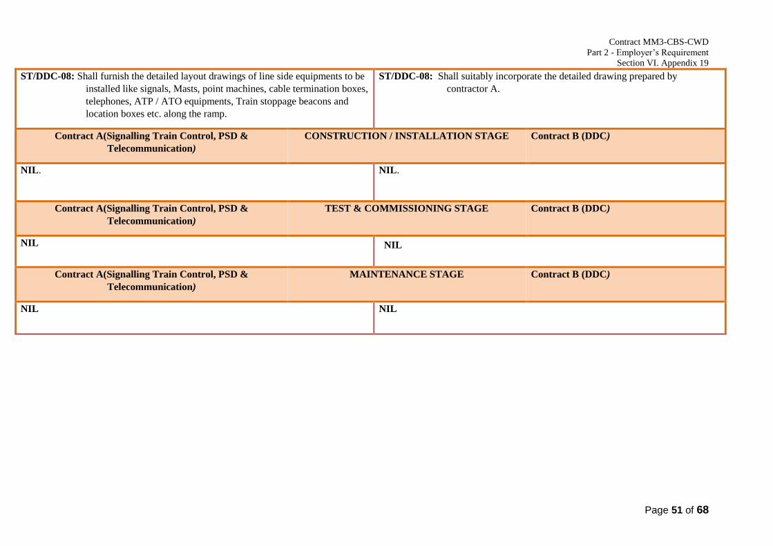
Contract MM3-CBS-CWD
Part 2 - Employer’s Requirement
Section VI. Appendix 19
Page 51 of 68
ST/DDC-08: Shall furnish the detailed layout drawings of line side equipments to be
installed like signals, Masts, point machines, cable termination boxes,
telephones, ATP / ATO equipments, Train stoppage beacons and
location boxes etc. along the ramp.
ST/DDC-08: Shall suitably incorporate the detailed drawing prepared by
contractor A.
Contract A(Signalling Train Control, PSD &
Telecommunication)
CONSTRUCTION / INSTALLATION STAGE Contract B (DDC)
NIL. NIL.
Contract A(Signalling Train Control, PSD &
Telecommunication)
TEST & COMMISSIONING STAGE Contract B (DDC)
NIL NIL
Contract A(Signalling Train Control, PSD &
Telecommunication)
MAINTENANCE STAGE Contract B (DDC)
NIL NIL

Contract MM3-CBS-CWD
Part 2 - Employer’s Requirement
Section VI. Appendix 19
Page 52 of 68
N6 -INDICATIVE INTERFACE SHEET OF SIGNALLING, TRAIN CONTROL, PSD & TELECOMMUNICATION (STPT) & DEPOT CIVIL WORKS
(CWD)
Mumbai Metro Interface Sheet Contract A STPT Contract B AFC Rev # : A2
Date: 06/01/17
Approved by :
ST (Signalling Train Control, PSD &Telecommunication)
Lead Contract
CWD (Civil Work Depot)
Participating Contract
First issue:
GC issued by :
Checked by :
Interface description brief / Key elements (time schedule, physical, functional, ...) :
1.General Interface details between the Signalling Train control, PSD & Telecommunication vs. Civil Work Depot (CWD)
Contract A(Signalling Train Control, PSD &
Telecommunication)
CONSTRUCTION / INSTALLATION STAGE Contract B(CWD)
ST/CWD-01: a) Shall specifiy technical room sizes and details like false floor, false
ceiling etc.
b) Arrange and install masts antenna, antenna connections, aviation
warning and Mast earthing.
ST/CWD-01: Shall provide the:
a) Concerned rooms and other facilities mentioned here.
b) Cable routing arrangements to enable contractor A and the E&M
contractor to fix containments and lay cables.
c) Fixing arrangements as needed for heavy equipment, cutouts,
embedded conduits etc. for all S & T equipments for provide and
assist in fixture for the mast and arrangements for maintenance
access to the radio masts.
ST/CWD-02: Shall provide, install and fix all Telecommunication equipment,
including cables with connections to individual devices.
ST/CWD-02: Shall provide the required heavy foundations and raceway. Shall
provide the necessary support to contractor A during the installation
of S & T equipment.

Contract MM3-CBS-CWD
Part 2 - Employer’s Requirement
Section VI. Appendix 19
Page 53 of 68
ST/CWD-03: Shall plan and coordinate the installation of S & T equipment with the
progress of depot works, in accordance with the global depot
coordination.
ST/CWD-03: Shall plan and coordinate the progress of depot works with the
progress of S & T equipment installation in the depot.
ST/CWD-04: Shall install S&T UPS power cables from the distribution panel to all
concerned rooms. Shall also arrange for distribution of power supply to
all field S&T Equipments.
ST/CWD-04: Shall provide necessary cutouts and embedded conduits for routing
and mounting of cables.
ST/CWD-05: Shall install the Access control & intrusion detection system for the
OCC / DCC areas as well as the depot area and Aarey station.
ST/CWD-05: Shall ensure that the requirements are fully met.
Co-ordinate with S&T contractor particularly for Access control
and intrusion detection. For other systems general assistance as
needed by S&T contractor shall be extended.
ST/CWD-06: Shall prepare foundations and install all track side signalling
equipments like Signals, cable termination boxes, Point machines, axle
counters, etc., in the depot
ST/CWD-06: Shall provide concrete works with expansion joints before track
slab is laid as per interface drawing
ST/CWD-07: Shall install the line side S & T equipments like signals, Masts,
ATP/ATO equipments, train stoppage beacons, location boxes, point
machines, cable termination boxes, telephones, axle counters, along
the ramp.
ST/CWD-07: Shall provide the necessary arrangements to install line side S &
T equipments like signals, Masts, ATP / ATO equipments, train
stoppage beacons, location boxes, point machines, cable
termination boxes, telephones,axle counters, etc along the ramp.
ST/CWD-08: a) Shall install the MML3 LAN in the Depot all buildings in Depot,
Aarey station to cover all the locations indicated by contractor A.
b) Shall extend the FOTS-FO, FOTS-IP to all buildings in the depot
area and terminate at a central distribution point in each building.
ST/CWD-08: a) Shall provide necessary cutouts and embedded conduits for
routing and mounting of LAN cables.
b) shall facilitate
ST/CWD-09: Shall install the PA, telephone, CCTV depot and Aarey station. ST/CWD-09: Shall provide necessary assistance to install the PA, telephone,
CCTV system.
ST/CWD-10: Shall supply mountings and fixtures to Depot contractor ST/CWD-10: Shall install and assist in mounting and fixing arrangements for
heavy equipments like CCTV monitors, display boards, clocks etc
during the construction as per ST requirements.
Keeping the structure strength in mind

Contract MM3-CBS-CWD
Part 2 - Employer’s Requirement
Section VI. Appendix 19
Page 54 of 68
ST/CWD-11: Shall install the equipments at OCC Depot and station like staff
protection keys locks, emergency stop plungers, PIDS, PA System,
Clocks, CCTV cameras and TV equipment etc
ST/CWD-11: Shall facilitate
ST/CWD-12: Shall lay all necessary cables in Depot, station and other areas ST/CWD-12: Shall arrange Ducts and track crossings as per requirements. The
material likes pipes etc. will be supplied by the S&T department.
ST/CWD-13: Shall furnish cable routing plan to Contractor B for PSD ST/CWD-13: Shall construct cable ducts/containment for PSD cable
ST/CWD-14: Shall install PSD at platforms of station ST/CWD-14: Shall co-ordinate and assist installation
ST/CWD-15: ST shall conduct Ergonomic study for OCC. The Floor levels,
acoustic treatment, acoustic parameters of OCC should be provided by
STPT to Civil Depot Contractor.
ST/CWD-15: Depot Civil shall be doing the False Floors and False Ceilings in
consultation with Contractor A.
Contract A(Signalling Train Control, PSD &
Telecommunication)
TEST & COMMISSIONING STAGE Contract B (CWD)
ST/CWD-16: Shall conduct testing jointly with depot, OHE and Rolling Stock
Contractors.
ST/CWD-16: Shall attend the joint testing with S & T, OHE and Rolling Stock
Contractors.
Contract A(Signalling Train Control, PSD &
Telecommunication)
MAINTENANCE STAGE Contract B(CWD)
NIL NIL
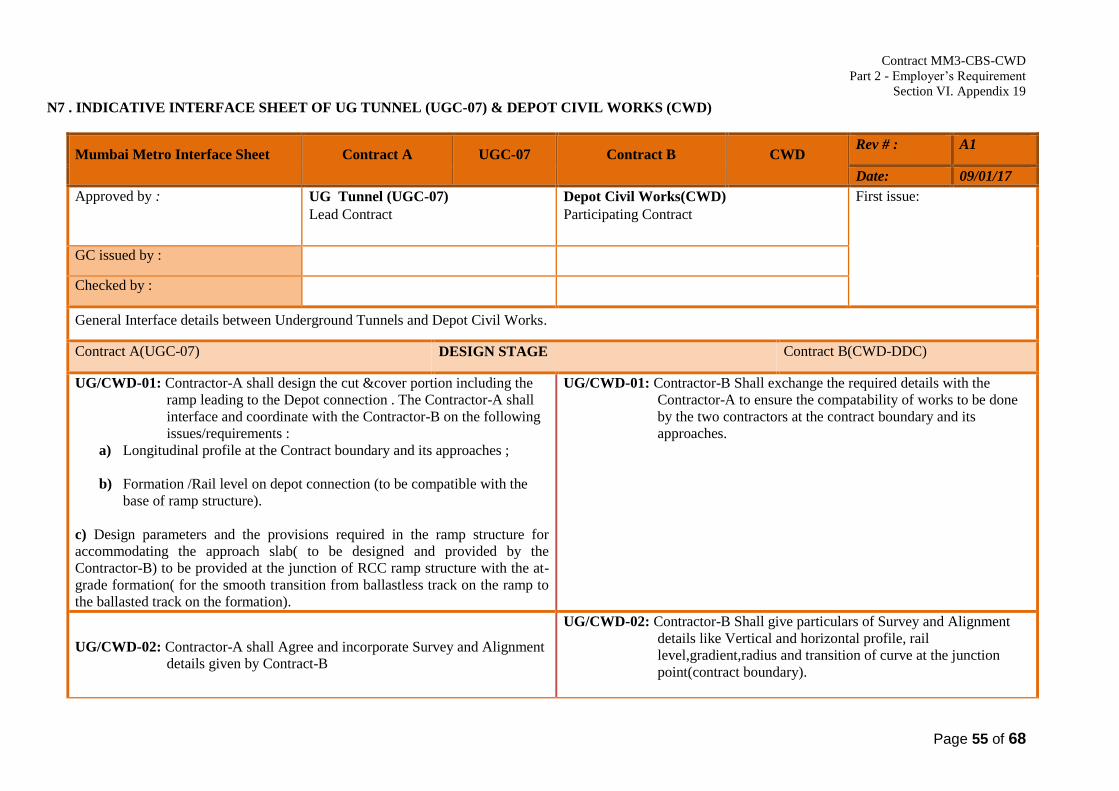
Contract MM3-CBS-CWD
Part 2 - Employer’s Requirement
Section VI. Appendix 19
Page 55 of 68
N7 . INDICATIVE INTERFACE SHEET OF UG TUNNEL (UGC-07) & DEPOT CIVIL WORKS (CWD)
Mumbai Metro Interface Sheet Contract A UGC-07 Contract B CWD Rev # : A1
Date: 09/01/17
Approved by :
UG Tunnel (UGC-07)
Lead Contract
Depot Civil Works(CWD)
Participating Contract
First issue:
GC issued by :
Checked by :
General Interface details between Underground Tunnels and Depot Civil Works.
Contract A(UGC-07) DESIGN STAGE Contract B(CWD-DDC)
UG/CWD-01: Contractor-A shall design the cut &cover portion including the
ramp leading to the Depot connection . The Contractor-A shall
interface and coordinate with the Contractor-B on the following
issues/requirements :
a) Longitudinal profile at the Contract boundary and its approaches ;
b) Formation /Rail level on depot connection (to be compatible with the
base of ramp structure).
c) Design parameters and the provisions required in the ramp structure for
accommodating the approach slab( to be designed and provided by the
Contractor-B) to be provided at the junction of RCC ramp structure with the at-
grade formation( for the smooth transition from ballastless track on the ramp to
the ballasted track on the formation).
UG/CWD-01: Contractor-B Shall exchange the required details with the
Contractor-A to ensure the compatability of works to be done
by the two contractors at the contract boundary and its
approaches.
UG/CWD-02: Contractor-A shall Agree and incorporate Survey and Alignment
details given by Contract-B
UG/CWD-02: Contractor-B Shall give particulars of Survey and Alignment
details like Vertical and horizontal profile, rail
level,gradient,radius and transition of curve at the junction
point(contract boundary).

Contract MM3-CBS-CWD
Part 2 - Employer’s Requirement
Section VI. Appendix 19
Page 56 of 68
Mumbai Metro Interface Sheet Contract A UGC-07 Contract B CWD Rev # : A1
Date: 09/01/17
UG/CWD-03: Contractor-A shall Agree with the drainage scheme duly
ensuring the compatibility and incorporate the drainage
system/measures in the beginning of ramp given by Contractor-
B.
UG/CWD-03: Contractor-B Shall design the drainage arrangements in depot at
the junction of RCC ramp structure with the at-grade formation
and its approaches to prevent ( to the maximum extent
possible) water entering from depot to the ramp/tunnels etc.
and furnish the details of drainage System/measures required to
be incorporated in the ramp structure.
Reference documents: Reference documents:
Contract A(UGC-07) CONSTRUCTION / INSTALLATION STAGE Contract B(CWD)
UG/CWD-04: Shall review the measures and agree for their adequacy
UG/CWD-04: Take measures and ensure that water doesn’t enter from depot
to the ramp/tunnels .
UG/ CWD -05: Accept survey details of Depot connecting section
UG/CWD-05: Accept survey details of cut & cover portion including the
ramp.
Reference documents: Reference documents:
Contract A(UGC-07) TEST & COMMISSIONING STAGE Contract B(CWD)
UG/CWD -06:Contractor-A shall co-ordinate with contractor-B and rolling
stock contractor while conducting trial tests regarding
kinematic and structural gauge checking and undertake
corrective works in the profile wherever necessary.
UG/CWD-06: Contractor-B should attend for testing and commissioning work
and do Corrective works in the profile where ever necessary
Reference documents : Reference documents:
Contract MM3-CBS-CWD
Part 2 - Employer’s Requirement
Section VI. Appendix 19
Page 57 of 68
Mumbai Metro Interface Sheet Contract A UGC-07 Contract B CWD Rev # : A1
Date: 09/01/17
Contract A(CWD) MAINTENANCE STAGE Contract B(RST)
NIL NIL
Reference documents: Reference documents:

Contract MM3-CBS-CWD
Part 2 - Employer’s Requirement
Section VI. Appendix 19
Page 58 of 68
N8. INDICATIVE INTERFACE SHEET OF DEPOT CIVILWORKS (CWD) & DEPOT E & M STATION(DEM)
Mumbai Metro Interface Sheet Contract A CWD Contract B DEM Rev # : A1
Date: 09/01/17
Approved by :
Depot Civil Works(CWD)
Lead Contract
DEM (DEM Stations)
Participating Contract
First issue:
GC issued by :
Checked by :
General Interface details between Civil work Depot(CWD) and DEM Stations(DEM)
Contract A(CWD-DDC) DESIGN STAGE Contract B(DEM)
CW/DEM-01:Shall provide the E&M requirement in the architectural
drawings.
CW/DEM-01: Shall advice to Contract “A” regarding E&M requirement
such as required cutout, sleeves, wall opening for all MEP
services to be provided in architectural and structural design at
Depot and Array Station.
CW/DEM-02: Shall coordinate and provide requirement of Contract “B” in
drawings
CW/DEM-02: Ensure all the required cut outs, sleeves and other provisions
for E&M services as VAC, Fire Fighting, cable trays, etc.
are in place as per the drawing and requirement.
CW/DEM-03: Shall include Contract “B” requirement in the civil drawings.
CW/DEM-03: Shall advice the required trench layout for electrical cables
with three types of trenches, one for HT cables, one for LT
cables, and one combined for both LT & HT cables (required
number of trenches will be designed considering minimum
750mm horizontal sufficient space for installation and
maintenance works) pipe lines, etc. for various E&M
services to be provided in the civil drawings.

Contract MM3-CBS-CWD
Part 2 - Employer’s Requirement
Section VI. Appendix 19
Page 59 of 68
Mumbai Metro Interface Sheet Contract A CWD Contract B DEM Rev # : A1
Date: 09/01/17
CW/DEM-04: Shall incorporate Contract “B” requirement in his false ceiling
design. (Reflected Ceiling Plan).
CW/DEM-04: Shall provide required drawings to Contract “A” of lighting
fixture mouting/fixing details, layout & design, fire alarm
&fire fighting equipment’s location, VAC equipments etc.
CW/DEM-05: Shall incorporate Contract “B” E&M equipment loads in
Structural design.
CW/DEM-05: Shall submit the E&M equipment’s loads (weight) details and
GAD to Contract “A”.
CW/DEM-06: Shall incorporate and provide the lifting hooks / chain pulley
with rail arrangement for other E&M services as required.
CW/DEM-06: Shall submit the lifting hook, chain pulley with rail
arrangement details / load requirements for all MEP services to
Contract “A”.
CW/DEM-07:Shall incorporate foundation for Transformers, DG’s,
Compressor, VAC equipment, Firefighting pumps and other
E&M equipment as required.
CW/DEM-07: Shall provide the Dimensional and load (in kgs / ton) details of
E&M to Contract “A”.
CW/DEM-08: Shall design and construct the fire water tank, raw water tank
and treated water tank.
CW/DEM-08: Shall coordinate and provide water requirement for fire
fighting system, raw water and treated water to Contract “A”.
CW/DEM-09: Cable trench and manholes with top cover should be provided
by civil. (RCC for External Trenches and Steel for Internal
Trenches).
CW/DEM-09: Shall advice Contract “A” the E&M requirement with trench
and manhole layout plan, etc. details and drawings.
CW/DEM-10: Shall coordinate & provide Contractor “B” requirement CW/DEM-10: Closing and sealing of cable trench at entry / exit point of
trench / manholes to the building from external trench.

Contract MM3-CBS-CWD
Part 2 - Employer’s Requirement
Section VI. Appendix 19
Page 60 of 68
Mumbai Metro Interface Sheet Contract A CWD Contract B DEM Rev # : A1
Date: 09/01/17
CW/DEM-11: Shall provide the I/O points on open protocol for plumbing
pumps, STP & ETP equipments, control panels, etc to Contract
“B”.
CW/DEM-11: Shall integrate with Depot E&M SCADA or BMS System.
CW/DEM-12: Shall provide electrical power requirement for ETP, STP to
Contract “B” for designing power distribution.
CW/DEM-12: Shall design and incorporate in the electrical distribution the
requirements of Contract “A”.(only power cables)
CW/DEM-13: Shall co-ordinate & provide area required for earthing, the Soil
resistivity report, etc. for Earth Mat Design.
CW/DEM-13: Shall advice to Contract “A” Earth mat area and shall design
the Earth Mat in coordination with Civil Contractor.
CW/DEM-14: Shall provide the Earthing and Bonding Details for Civil and
Steel Structures.
CW/DEM-14: Shall advice to Contract “A” E&M Earthing design details
requirements.
CW/DEM-15: Shall provide to Contract “B” wall partition, glass glazing, roof
sheeting, etc. specification and other details for designing of
VAC works (In room wise matrix form).
CW/DEM-15: Shall detail VAC designs as per room detail inputs from
Contract “A”. (Shall detail A/c, Non A/c rooms etc).
CW/DEM-16: Over head crane weight shall be incorporated in workshop’s
structural design as per requirement of contract “B”.
CW/DEM-16: Shall advice to contact “A” the Overhead Crane details like
types, Quantity, Capacity, weight, etc.for incorporation in
structural design.
CW/DEM-17: Shall design pump sizing, rating and head for the water supply
pumps, sump pumps, horticulture pupms etc.
CW/DEM-17: Shall incorporate and design Control panel and electrical
distribution system accordingly.

Contract MM3-CBS-CWD
Part 2 - Employer’s Requirement
Section VI. Appendix 19
Page 61 of 68
Mumbai Metro Interface Sheet Contract A CWD Contract B DEM Rev # : A1
Date: 09/01/17
Contract A(CWD) CONSTRUCTION / INSTALLATION STAGE Contract B(DEM)
CW/DEM-18:Shall provide the Contract “B” requirements / details as
mentioned under Design Stage above.
CW/DEM-18: Shall coordinate, verify and submit acceptance to Contract “A”
works.
CW/DEM-19:Shall share and incorporate the E&M requirements in the
architectural false ceiling drawings
CW/DEM-19:Shall coordinate and advice with Contract “A” for requirement.
CW/DEM-20:Shall provide the space for installation of raceways before
finished flooring works.
CW/DEM-20:Shall install the required raceways before flooring works.
CW/DEM-21:Shall install aligned Steel Girders for Overhead crane long travel
movement.
CW/DEM-21:Shall verify the requiremets provided by contract “A”.
CW/DEM-22:Shall advice to Contract “B” the installation instructions for
welding rails and all other peripheral accessories for Overhead
Crane operations.
CW/DEM-22:Shall follow the advice of Contract “A” for completion of
welding works for Crane operations.
CW/DEM-23:Fixing work of Supporting arrangement for High Bay/Medium
Bay Lighting to be provided.
CW/DEM-23:Shall arrange Lighting luminaires etc. with fixing arrangement.
CW/DEM-24:Excavation and closing of area identified for earth mat will be
done by Contract “A” in coordination with Contract “B”.
CW/DEM-24:Shall share the design details of earth mat for excavation and
cloaing of pits to Contract “A”.

Contract MM3-CBS-CWD
Part 2 - Employer’s Requirement
Section VI. Appendix 19
Page 62 of 68
Mumbai Metro Interface Sheet Contract A CWD Contract B DEM Rev # : A1
Date: 09/01/17
CW/DEM-25:Contract “A” shall provide three types of cable trench with cover
for electrical cables (first for onlyLT cables, second for only HT
cables and third for both HT & LT combined), pipe lines, and
Drainage lines for various MEP services in Depot to be provided
in the civil drawings.
CW/DEM-25:Shall coordinate and advice to Contract “A”the requirements
CW/DEM-26:Shall provide piping network for water supply system, strom
water drainage system, horticulture sypply system and coordinate
with contract “B” in installation of pumps.
CW/DEM-26:Shall provide water supply pumps, sump pumps, horticulture
pupms etc. as requirement of Contract “A”.
Reference documents: Reference documents:
Contract A(CWD) TEST & COMMISSIONING STAGE Contract B(DEM)
CW/DEM-27: Contract “A” shall conduct test run jointly with Contract “B”
corrective works in the profile wherever necessary.
CW/DEM-27: Contract “A” shall conduct test run jointly with Contract “B”
Reference documents :
Reference documents:
Contract A(CWD) MAINTENANCE STAGE Contract B(DEM)
NIL NIL
Reference documents: Reference documents:

Contract MM3-CBS-CWD
Part 2 - Employer’s Requirement
Section VI. Appendix 19
Page 63 of 68
N9. INDICATIVE INTERFACE SHEET OF DEPOT CIVIL WORKS (CWD) AND PYLON TERMINATION CONTRACTOR (PYL)
Mumbai Metro Interface Sheet Contract A CWD Contract B PYL Rev # : A1
Date: 09/01/17
Approved by :
Depot Civil Works(CWD)
Lead Contract
Pylon Termination Contractor (PYL)
Participating Contract
First issue:
GC issued by :
Checked by :
General Interface details between Depot Civil Works and Pylon Termination Contractor
Contract A(CWD) CONSTRUCTION / INSTALLATION STAGE Contract B(PYL)
CW/PY-01:Shall construct diversion road based on Termination yard layout
CW/PY-01:Shall mark termination yard layout on ground including working
space required for construction of termination yard.
CW/PY-02:Shall evolve construction methodology for underpass so that
already constructed cable duct not damaged.
CW/PY-02:Shall complete cable duct nearer to underpass on priority and
vacate the area for Contract A.
CW/PY-03:Shall undertake construction work at existing pylons(4 nos) location
only after Termination yard is commissioned and existing pylons including
foundations dismantled.
CW/PY-03:Shall dismantle existing pylons including foundation without
disturbing adjacent construction work carried out by Contract A.l
Reference documents: Reference documents:
Contract A(CWD) TEST & COMMISSIONING STAGE Contract B(PYL)

Contract MM3-CBS-CWD
Part 2 - Employer’s Requirement
Section VI. Appendix 19
Page 64 of 68
Mumbai Metro Interface Sheet Contract A CWD Contract B PYL Rev # : A1
Date: 09/01/17
Reference documents : Reference documents:
Contract A(CWD) MAINTENANCE STAGE Contract B(PYL)
NIL NIL
Reference documents: Reference documents:

Contract MM3-CBS-CWD
Part 2 - Employer’s Requirement
Section VI. Appendix 19
Page 65 of 68
N10 . INDICATIVE INTERFACE SHEET OF DEPOT EQUIPMENT(DEQ) AND DETAILED DESIGN CONSULTANT(DDC)
Mumbai Metro Interface Sheet Contract A DEQ Contract B DDC Rev # : A0
Date: 03-02-2017
Approved by : Depot Equipment Contractor
(Interface Lead) Detailed Designed Consultant
(Interface Follower)
Last changes :
GC issued by :
GC Checked by :
General Interface details between Depot Contractor and Detailed Designed Consultant
Contract A (Depot Equipment) DESIGN STAGE Contract B (Detailed Designed Consultant)
DE/DDC-01: Under-floor wheel lathe along-with Chip crusher, conveyor
and Train Shunter – Shall provide details of civil requirements for
building, Machine foundation, flooring, pit, drainage, etc.
DE/DDC-01: Shall prepare the civil construction drawings along with
interfaces.
DE/DDC-02: Railcar lifting system for 4 cars (Pit jacks) – Shall provide
requirements for foundation of equipment, Pits etc.
DE/DDC-02: Shall prepare the civil construction drawings along with
interfaces.
DE/DDC-03: Mobile lifting jacks for 8 cars – Shall give requirements for Floor
Surface, markings etc.
DE/CW-03: Shall prepare the civil construction drawings along with
interfaces.
DE/DDC-04: Bogie Turn Table -Shall define the requirements for mounting
foundation etc. for Bogie Turntables
DE/DDC-04: Shall prepare the civil construction drawings along with
interfaces.
DE/DDC-05: Automatic Train Wash Plant - Shall define the floor and other
foundations including the pipeline ducts, drainage, tanks etc. for the train
wash plant.
To lay the cables/conduit etc. to provide the Control of the Train Wash
plant in DCC and shall co-ordinate the job with Depot Civil Works
DE/DDC-05: Shall prepare the civil construction drawings along with
interfaces.

Contract MM3-CBS-CWD
Part 2 - Employer’s Requirement
Section VI. Appendix 19
Page 66 of 68
Contractor.
DE/DDC-06: Bogie Testing Bench - Shall define the structure and foundation
of the testing bench and to define the Civil require the testing bench
DE/DDC-06: Shall prepare the civil construction drawings along with
interfaces.
DE/DDC-07: Air Compressor for shop air supply with Piping Network –
Shall provide details for mounting, mounting elements, flooring, openings,
trenches and other requirements.
To define and lay the piping network for the compressed air from
compressor room to workshop, etc.
DE/DDC-07: Shall prepare the civil construction drawings along with
interfaces.
DE/DDC-08: Pendant Type Travelling EOT cranes (for inspection bay &
workshop) - Shall define requirements for crane installation in inspection
bay and workshop. To clear of the ceiling or roof of the building.
DE/DDC-08: Shall prepare the civil construction drawings along with
interfaces.
DE/DDC-09: Any other Depot Equipment - Shall define the requirements for
civil construction.
DE/DDC-09: Shall prepare the civil construction drawings along with
interfaces.
Reference documents:
Reference documents:

Contract MM3-CBS-CWD
Part 2 - Employer’s Requirement
Section VI. Appendix 19
Page 67 of 68
N11 - INDICATIVE INTERFACE SHEET OF DETAILED DESIGN CONSULTANT(DDC) AND DEPOT CIVIL WORKS (CWD)
Mumbai Metro Interface Sheet Contract A DDC Contract B CWD Rev # : A0
Date: 03-02-2017
Approved by : Detailed Design Consultant
(Interface Lead) Depot Civil Works Contractor
(Interface Follower)
Last changes :
GC issued by :
GC Checked by :
General Interface details between Detailed Design Consultant Works and Depot Civil Works
Contract A (Detailed Design Consultant) CONSTRUCTION STAGE Contract B (Depot Civil Works)
DDC/CW-01: Under-floor wheel lathe along-with Chip crusher, conveyor
and Train Shunter - Shall prepare the civil construction drawings along
with interfaces.
DDC/CW-01: Shall construct Building, Pit, Floor, and Foundation for lathe,
gantry for crane, drainage and electrical conduits for the Pit and
opening in the Wall for Chip conveyor and all other civil requirements.
DDC/CW-02: Railcar lifting system for 4 cars (Pit jacks) - Shall prepare the
civil construction drawings along with interfaces.
DDC/CW-02:Shall construct to build according to the requirements.
The Depot Civil Works Contractor to provide the drainage for the Pit.
DDC/CW-03: Mobile lifting jacks for 8 cars - Shall prepare the civil
construction drawings along with interfaces.
DDC/CW-03: Shall construct according to the requirements
DDC/CW-04: Bogie Turn Table - Shall prepare the civil construction drawings
along with interfaces.
DDC/CW-04: Shall construct according to the requirements
DDC/CW-05: Automatic Train Wash Plant - Shall prepare the civil
construction drawings along with interfaces.
DDC/CW-05: Shall construct according to the requirements. Provide the
epoxy painting at the Train Wash Plant floor area if necessary.
Depot Civil Works Contractor to conceal the Conduits etc. as defined
and laid by the Depot Equipment Supplier.

Contract MM3-CBS-CWD
Part 2 - Employer’s Requirement
Section VI. Appendix 19
Page 68 of 68
DDC/CW-06: Bogie Testing Bench - Shall prepare the civil construction
drawings along with interfaces.
DDC/CW-06: Shall construct according to the requirements.
DDC/CW-07: Air Compressor for shop air supply with Piping Network - :
Shall prepare the civil construction drawings along with interfaces.
DDC/CW-07: Shall construct according to the requirements.
To provide the passageway I trenches, etc. for the compressor piping
network as defined by the Depot Equipment supplier.
DDC/CW-08: Pendant Type Travelling EOT cranes (for inspection bay &
workshop) - Shall prepare the civil construction drawings along with
interfaces.
DDC/CW-08: Shall construct according to the requirements. Build the
columns, install girders, corbels/trusses, etc. to accommodate the
mounting of the cranes.
DDC/CW-09: Any other Depot Equipment - Shall prepare the civil
construction drawings along with interfaces.
DDC/CW-09: Shall construct according to the requirements.
Reference documents:
Reference documents: