name 345 welding technology lecture 07 shielded...
TRANSCRIPT

NAME 345Welding Technology
Lecture – 07
Shielded Metal Arc Welding (SMAW)
Md. Habibur Rahman
Lecturer Department of Naval Architecture & Marine Engineering
Bangladesh University of Engineering & TechnologyDhaka-1000, Bangladesh
SMAW Welding
2
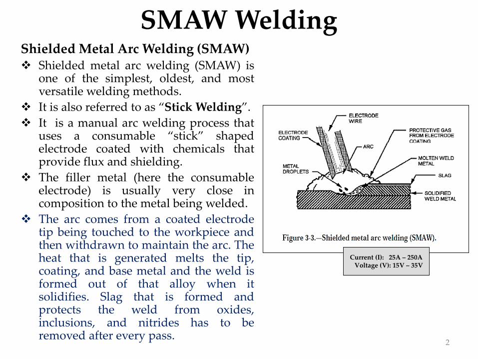
Shielded Metal Arc Welding (SMAW)❖ Shielded metal arc welding (SMAW) is
one of the simplest, oldest, and mostversatile welding methods.
❖ It is also referred to as “Stick Welding”.
❖ It is a manual arc welding process thatuses a consumable “stick” shapedelectrode coated with chemicals thatprovide flux and shielding.
❖ The filler metal (here the consumableelectrode) is usually very close incomposition to the metal being welded.
❖ The arc comes from a coated electrodetip being touched to the workpiece andthen withdrawn to maintain the arc. Theheat that is generated melts the tip,coating, and base metal and the weld isformed out of that alloy when itsolidifies. Slag that is formed andprotects the weld from oxides,inclusions, and nitrides has to beremoved after every pass.
Current (I): 25A – 250AVoltage (V): 15V – 35V

SMAW Welding
3
Schematic Diagram of SMAW
Schematic Diagram of Shielded Metal Arc Welding (SMAW)

SMAW Welding
4
How to Strike and Establish an Arc
❖ A welding arc is maintained when the welding current is forced across a gapbetween the electrode tip and the base metal. A welder must be able to strikeand establish the correct arc easily and quickly.
❖ There are two general method to strike the arc:
i. Scratching
ii. Tapping
Scratching Method❖ The scratching method is easier for
beginners and when using an AC machine.The electrode is moved across the plateinclined at an angle, as you would strike asmatch. As the electrode scratches the platean arc is struck. When the arc has formed,withdraw the electrode momentarily toform an excessively long arc, then return tonormal arc length.

SMAW Welding
5
How to Strike and Establish an Arc (Contd.)
Tapping Method❖ In the tapping method, the electrode is moved downward to the base metal
in a vertical direction. As soon as it touches the metal it is withdrawnmomentarily to form an excessively long arc, then returned to normal arclength.
6
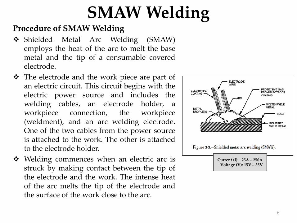
SMAW WeldingProcedure of SMAW Welding
❖ Shielded Metal Arc Welding (SMAW)employs the heat of the arc to melt the basemetal and the tip of a consumable coveredelectrode.
❖ The electrode and the work piece are part ofan electric circuit. This circuit begins with theelectric power source and includes thewelding cables, an electrode holder, aworkpiece connection, the workpiece(weldment), and an arc welding electrode.One of the two cables from the power sourceis attached to the work. The other is attachedto the electrode holder.
❖ Welding commences when an electric arc isstruck by making contact between the tip ofthe electrode and the work. The intense heatof the arc melts the tip of the electrode andthe surface of the work close to the arc.
Current (I): 25A – 250AVoltage (V): 15V – 35V
7
SMAW Welding
7
Procedure of SMAW Welding (Contd.)
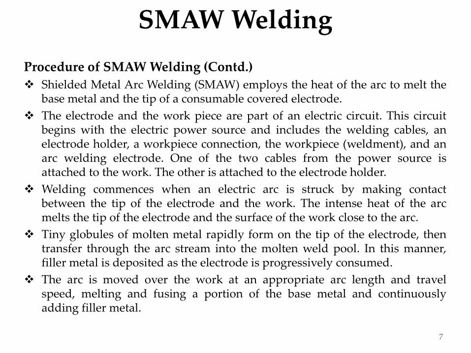
❖ Shielded Metal Arc Welding (SMAW) employs the heat of the arc to melt thebase metal and the tip of a consumable covered electrode.
❖ The electrode and the work piece are part of an electric circuit. This circuitbegins with the electric power source and includes the welding cables, anelectrode holder, a workpiece connection, the workpiece (weldment), and anarc welding electrode. One of the two cables from the power source isattached to the work. The other is attached to the electrode holder.
❖ Welding commences when an electric arc is struck by making contactbetween the tip of the electrode and the work. The intense heat of the arcmelts the tip of the electrode and the surface of the work close to the arc.
❖ Tiny globules of molten metal rapidly form on the tip of the electrode, thentransfer through the arc stream into the molten weld pool. In this manner,filler metal is deposited as the electrode is progressively consumed.
❖ The arc is moved over the work at an appropriate arc length and travelspeed, melting and fusing a portion of the base metal and continuouslyadding filler metal.

8
SMAW Welding
8
Procedure of SMAW Welding (Contd.)
❖ Since the arc is one of the hottest of the commercial sources of heat[temperatures above 9000˚F (5000˚C) have been measured at its center],melting of the base metal takes place almost instantaneously upon arcinitiation.
❖ If the welds are made in either the flat or the horizontal position, metaltransfer is induced by the force of gravity, gas expansion, electric andelectromagnetic forces, and surface tension. For welds in other positions,gravity works against the other forces.

9
SMAW Welding
9
Electrodes
❖ In general, all electrodes are classified into five main groups:
i. Mild steel ii. High-carbon steel iii. Special alloy steel iv. Cast iron v. Nonferrous
❖ The widest range of arc welding is done with electrodes in the mild steelgroup.
❖ Electrodes are classified as either bare or shielded. The original bareelectrodes were exactly as their implied – bare. Today, they have a lightcovering, but even with this improvement they are rarely used because oftheir limitations. They are difficult to weld with, produce brittle welds, andhave low strength.
❖ Just about all welding is done with shielded electrodes. The shieldedelectrode has a heavy coating of several chemicals, such as cellulose, titaniasodium, low-hydrogen sodium, or iron powder.
❖ Each of the chemicals in the coating serves a particular function in thewelding process. In general, their main purpose are to induce easier arcstarting, stabilize the arc, improve weld appearance and penetration, reducespatter, and protect the molten metal from oxidation or contamination by thesurrounding atmosphere.

10
SMAW Welding
10
Electrode Selection
❖ Several factors are critical when you choose all electrode for welding. Thewelding position is particularly significant.
❖ As a rule of thumb, you should never use an electrode that has a diameterlarger than the thickness of the metal that you are welding.
❖ Position and the type of joint are also factors in determining the size of theelectrode.
❖ A small-diameter electrode is always used to run the root pass. This is doneto ensure full penetration at the root of the weld.
❖ Larger electrodes make it too difficult to control the deposited metal. Foreconomy, you should always use the largest electrode. The larger sizes notonly allow the use of higher currents but also require fewer stops to changeelectrodes.
❖ Deposit rate and joint preparation are also important in the selection of anelectrode.
11
SMAW Welding
11
Electrode Selection (Contd.)
❖ Electrodes for welding mild steel can be classified as fast freeze, fill freeze,and fast fill.
❖ FAST-FREEZE electrodes produce a snappy, deep penetrating arc and fast-freezing deposits. They are commonly called reverse-polarity electrodes,even though some can be used on ac. These electrodes have little slag andproduce flat beads. They are widely used for all-position welding for bothfabrication and repair work.
❖ FILL-FREEZE electrodes have a moderately forceful arc and a deposit ratebetween those of the fast-freeze and fast-fill electrodes. They are commonlycalled the straight-polarity electrodes, even though they may be used on ac.These electrodes have complete slag coverage and weld deposits withdistinct, even ripples. They are the general-purpose electrode for aproduction shop and are also widely used for repair work they can be usedin all positions, but fast-freeze electrodes are still preferred for vertical andoverhead welding.

12
SMAW Welding
12
Electrode Selection (Contd.)
❖ FAST-FILL electrodes are the heavy coated, iron powder electrodes with asoft arc and fast deposit rate. These electrodes have a heavy slag and produceexceptionally smooth weld deposits. They are generally used for productionwelding where the work is positioned for flat welding.
❖ Another group of electrodes are the low-hydrogen type that was developedfor welding high-sulfur and high-carbon steel. These electrodes produce X-ray quality deposits by reducing the absorption of hydrogen that causesporosity and cracks under the weld bead.
❖ Welding stainless steel requires an electrode containing chromium andnickel. All stainless steels have low-thermal conductivity that causeselectrode overheating and improper arc action when high currents are used.In the base metal, it causes large temperature differentials between the weldand the rest of the work, which warps the plate. A basic rule in weldingstainless steel is to avoid high currents and high heat. Another reason forkeeping the weld cool is to avoid carbon corrosion.
❖ The basic rule in selecting electrodes is to pick one that is similar incomposition to the base metal.
13
SMAW Welding
13
Selecting the Type of Current
❖ The welding current used for stick welding may be either alternating currentor direct current depending on the electrode being used.
❖ When using dc welding machines, you can weld with either straight polarityor reverse polarity.
❖ Polarity is the direction of the current flow in a circuit, as shown in figure.
❖ If the electrode is connected to positive polarity, the workpiece must beconnected to negative polarity. This connection is called 'positive polarity' or‘electrode positive’. In America, the term ‘reverse polarity’ is used about sucha connection.
❖ If the electrode is connected to negative polarity, the term used is ‘electrodenegative’. In the US, the term ‘straight polarity’ is preferred.
❖ When you use straight polarity, the majority of the heat is directed towardthe workpiece. When you use reverse polarity, the heat is concentrated on theelectrode. In some welding situations, it is desirable to have more heat on theworkpiece because of its size and the need for more heat to melt the basemetal than the electrode; therefore, when making large heavy deposits, youshould use STRAIGHT POLARITY.

14
SMAW Welding
14
Selecting the Type of Current

15
SMAW Welding
15
Selecting the Type of Current (Contd.)❖ On the other hand, in overhead welding it is necessary to rapidly freeze the filler
metal so the force of gravity will not cause it to fall. When you use REVERSEPOLARITY, less heat is concentrated at the workpiece. This allows the filler metalto cool faster, giving it greater holding power. Cast-iron arc welding is anothergood example of the need to keep the workpiece cool; reverse polarity permits thedeposits from the electrode to be applied rapidly while preventing overheating inthe base metal.
❖ In general, straight polarity is used for all mild steel, bare, or lightly coatedelectrodes. With these types of electrodes, the majority of heat is developed at thepositive side of the current, the workpiece. However, when heavy-coatedelectrodes are used, the gases given off in the arc may alter the heat conditions sothe opposite is true and the greatest heat is produced on the negative side.Electrode coatings affect the heat conditions differently. One type of heavy coatingmay provide the most desirable heat balance with straight polarity, while anothertype of coating on the same electrode may provide a more desirable heat balancewith reverse polarity.
❖ Reverse polarity is used in the welding of nonferrous metals, such as aluminum,bronze, Monel, and nickel. Reverse polarity is also used with some types ofelectrodes for making vertical and overhead welds.
❖ You can recognize the proper polarity for a given electrode by the sharp, cracklingsound of the arc. The wrong polarity causes the arc to emit a hissing sound, andthe welding bead is difficult to control.

16
SMAW Welding
16
Power Supply
❖ The power supply used in SMAW has constant current output, ensuring thatthe current (and thus the heat) remains relatively constant, even if the arcdistance and voltage change. This is important because most applications ofSMAW are manual, requiring that an operator hold the torch. Maintaining asuitably steady arc distance is difficult if a constant voltage power source isused instead, since it can cause dramatic heat variations and make weldingmore difficult.
❖ The preferred polarity of the SMAW system depends primarily upon theelectrode being used and the desired properties of the weld.
❖ Direct current with a negatively charged electrode (DCEN) causes heat tobuild up on the electrode, increasing the electrode melting rate anddecreasing the depth of the weld. Reversing the polarity so that the electrodeis positively charged (DCEP) and the workpiece is negatively chargedincreases the weld penetration.
❖ With alternating current the polarity changes over 100 times per second,creating an even heat distribution and providing a balance between electrodemelting rate and penetration.

17
SMAW Welding
17
Advantages Limitations
▪ The equipment is relatively simple,inexpensive, and portable.
▪ The filler metal, and the means ofprotecting it and the weld metalfrom harmful oxidation duringwelding are provided by thecovered electrode.
▪ Auxiliary gas shielding or granularflux is not required.
▪ The process is less sensitive to windand draft than gas shielded arcwelding processes.
▪ It can be used in areas of limitedaccess.
▪ The process is suitable for most ofthe commonly used metals andalloys.
▪ The process is discontinuous due tolimited length of the electrodes
▪ Due to flux coated electrode, the chancesof slag entrapment and other relateddefects are more as compared to MIG andTIG welding.
▪ Due to fumes and particles of slag, the arcand metal transfer is not very clear andwelding control in this process is a bitdifficult as compared to MIG welding.
▪ This process uses stick electrodes andthus it is slower as compared to MIGwelding.
▪ Current limits are lower than forcontinuous or automatic processes(reduces deposition rate)
▪ There is a lot of post-weld cleanupneeded if the welded areas are to lookpresentable.

18
SMAW Welding
18
Welding Arc Blow❖ Arc blow is the deflection of an electric arc from its normal path
due to magnetic forces. It is mainly encountered with dcwelding of magnetic materials, such as steel, iron, and nickel,but can also be encountered when welding nonmagneticmaterials.
❖ It will usually adversely affect appearance of the weld, causeexcessive spatter, and can also impair the quality of the weld.
❖ It is often encountered when using the shielded metal arcwelding process with covered electrodes. It is also a factor insemiautomatic and fully automatic arc welding processes.
❖ Arc blow causes the arc to wander while you are welding incorners on heavy metal or when using large coated electrodes.
❖ Direct current flowing through the electrode, workpiece, andground clamp generates a magnetic field around each of theseunits. This field can cause the arc to deviate from the intendedpath.
❖ The arc is usually deflected forward or backward along the lineof travel and may cause excessive spatter and incompletefusion.
❖ It also has the tendency to pull atmospheric gases into the arc,resulting in porosity. Arc blow is the, usually unwanted,deflection of the arc during arc welding.

19
SMAW Welding
19
Magnetic Arc Blow or Arc Wander
❖ Magnetic arc blow or "arc wander" is the deflection ofwelding filler material within an electric arc deposit by abuildup of magnetic force surrounding the weld pool.Magnetic arc blow is more common in DC welding thanin AC welding. It is experienced most when usingcurrents above 200 A or below 40 A.
❖ Magnetic arc blow can occur because of:
i. Workpiece connection, ii. Joint design, iii. Poor fit-up
iv. Improper settings v. Atmospheric conditions
❖ Arc blow tends to occur if the material being welded has residual magnetism at a certainlevel, particularly when the weld root is being made, and the welding current is directcurrent (DC positive or negative).
❖ This is due to interaction between the directional magnetic field of the welding arc and thedirectional field of the residual magnetism.
❖ Magnetic arc blow is popularly attributed to a change in the direction of current as it flowsinto and through the workpiece.
❖ Magnetic arc blow is known to begin at field densities as low as 10 gauss and becomes severeat densities of, equal to or greater than, 40 gauss; it is directional and can be classified asforward or backward moving along the joint, but can occasionally occur to the sidesdepending on the orientation of the poles to the workpiece.
20
SMAW Welding
20
Thermal Arc Blow
❖ Thermal arc blow is widely attributed to variations in resistance within thebase metal created by the weld pool as it is moved across the workpiece.
❖ Thermal arc blow occurs because an electric arc requires hot zones on theelectrode and workpiece plate to maintain a continuous flow of current in thearc stream.
❖ As the electrode advances along the work, the arc tends to lag behind, causedby reluctance of the arc to move to the colder plate. The ionized spacebetween the end of the electrode and the hot surface of the molten cratercreates a more conductive path than from the electrode to the colder.
❖ Thermal arc blow causes are:
i. Improper surface preparation
ii. Improper travel speed
❖ Thermal arc blow is not as severe as magnetic arc blow, but can still leaveundesirable defects in the weld deposit.

21
SMAW Welding
21
Factors Causing Arc Blow
i. Arc blow is caused by magnetic forces. The induced magnetic forces are notsymmetrical about the magnetic field surrounding the path of the weldingcurrent. The location of magnetic material with respect to the arc creates amagnetic force on the arc which acts toward the easiest magnetic path and isindependent of electrode polarity. The location of the easiest magnetic pathchanges constantly as welding progresses; therefore, the intensity and thedirection of the force changes.
ii. Welding current will take the easiest path but not always the most directpath through the work to the work lead connection. The resultant magneticforce is opposite in direction to the current from the arc to is independent ofwelding current polarity.

22
SMAW Welding
22
Factors Causing Arc Blow
iii. Arc blow is not as severe with alternating current because the inductionprinciple creates current flow within the base metal which creates magneticfields that tend to neutralize the magnetic field affecting the arc.
iv. The greatest magnetic force on the arc is caused by the difference resistanceof the magnetic path in then the base metal around the arc. The location ofthe work connection is of secondary importance, but may have an effect onreducing the total magnetic force on the arc. It is best to have the work leadconnection at the starting point of the weld. This is particularly true inelectro-slag welding where the work lead should be connected to the startingsump. On occasion, the work lead can be changed to the opposite end of thejoint. In sane cases, leads can be connected to both ends.
23
SMAW Welding
23
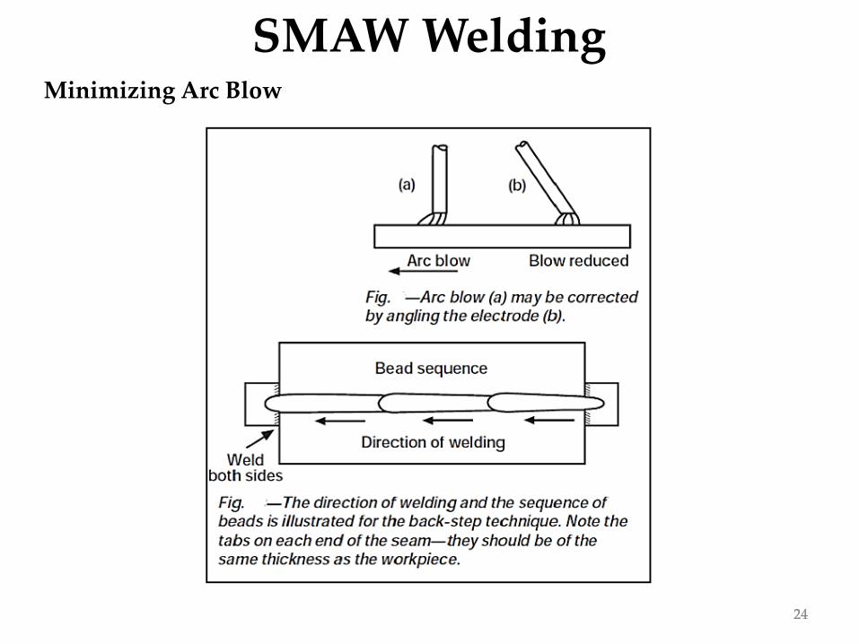
Minimizing Arc Blow
i. If DC current is being used with the shielded metal-arc process - especiallyat rates above 250 amps - a change to AC current may eliminate problems.
ii. Hold as short an arc as possible to help the arc force counteract the arc blow.
iii. Reduce the welding current - which may require a reduction in arc speed.
iv. Angle the electrode with the work opposite the direction of arc blow.
v. Make a heavy tack weld on both ends of the seam; apply frequent tack weldsalong the seam, especially if the fit-up is not tight.
vi. Weld toward a heavy tack or toward a weld already made.
vii. Use a back-step welding technique.
viii.Weld away from the workpiece connection to reduce back blow; weldtoward the workpiece connection to reduce forward blow.
ix. With processes where a heavy slag is involved, a small amount of back blowmay be desirable; to get this, weld toward the workpiece connection.
x. Wrap the work cable around the workpiece so that the current returning tothe power supply passes through it in such a direction that the magneticfield setup will tend to neutralize the magnetic field causing the arc blow.
24
SMAW Welding
24
Minimizing Arc Blow

25
SMAW Welding
25
Comparison chart of welds
Undercuts and overlapping in welding
Setting the length of an arc

26
SMAW Welding
26
Common Defects in SMAW
➢ Hot cracks
❖ Caused by excessive contraction of the metal as it cools.
❖ Excessive bead size
❖ May also be found at the root of the weld.
➢ Slag inclusions❖ Long arc
❖ Incomplete removal of slag on multi-pass welds.
➢ Undercutting
❖ Improper welding parameters;particularly the travel speed and arcvoltage.
➢ Porosity
❖ Atmospheric contamination or excessgas in the weld pool.
➢Toe Cracks❖Excessive heat and rapid cooling.
➢Underbead cracks❖Excessive hydrogen in weld pool
➢Microcracks❖Caused by stresses as weld cools.
➢Incomplete fusion❖Incorrect welding parameters or welding techniques.
Toe cracks
Underbead cracks
Microcracks
Incomplete fusion

27
SMAW Welding
27
Summery - - -1. … … …2. … … …3. … … …