nace rp 0169
TRANSCRIPT

NACE Standard RP0169-96Item No. 21001
StandardRecommended Practice
Control of External Corrosion on Underground orSubmerged Metallic Piping S ystems
This NACE International standard represents a consensus of those individual members who havereviewed this document, its scope, and provisions. Its acceptance does not in any respectpreclude anyone, whether he has adopted the standard or not, from manufacturing, marketing,purchasing, or using products, processes, or procedures not in conformance with this standard.Nothing contained in this NACE International standard is to be construed as granting any right, byimplication or otherwise, to manufacture, sell, or use in connection with any method, apparatus,or product covered by Letters Patent, or as indemnifying or protecting anyone against liability forinfringement of Letters Patent. This standard represents minimum requirements and should in noway be interpreted as a restriction on the use of better procedures or materials. Neither is thisstandard intended to apply in all cases relating to the subject. Unpredictable circumstances maynegate the usefulness of this standard in specific instances. NACE International assumes noresponsibility for the interpretation or use of this standard by other parties and acceptsresponsibility for only those official NACE International interpretations issued by NACEInternational in accordance with its governing procedures and policies which preclude theissuance of interpretations by individual volunteers.
Users of this NACE International standard are responsible for reviewing appropriate health,safety, environmental, and regulatory documents and for determining their applicability in relationto this standard prior to its use. This NACE International standard may not necessarily addressall potential health and safety problems or environmental hazards associated with the use ofmaterials, equipment, and/or operations detailed or referred to within this standard. Users of thisNACE International standard are also responsible for establishing appropriate health, safety, andenvironmental protection practices, in consultation with appropriate regulatory authorities ifnecessary, to achieve compliance with any existing applicable regulatory requirements prior to theuse of this standard.
CAUTIONARY NOTICE: NACE International standards are subject to periodic review, and maybe revised or withdrawn at any time without prior notice. NACE International requires that actionbe taken to reaffirm, revise, or withdraw this standard no later than five years from the date ofinitial publication. The user is cautioned to obtain the latest edition. Purchasers of NACEInternational standards may receive current information on all standards and other NACEInternational publications by contacting the NACE International Membership ServicesDepartment, P.O. Box 218340, Houston, Texas 77218-8340 (telephone +1 [281]228-6200).
Reaffirmed 1996-Sept-13Approved August 1969
NACE InternationalP.O. Box 218340
Houston, Texas 77218-8340+1 (281)228-6200
ISBN 1-57590-035-1©1996, NACE International

RP0169-96
NACE In
_______________________________________________________________________
Foreword
This standard recommended practice presents procedures and practices for achievingeffective control of external corrosion on buried or submerged metallic piping systems. Theserecommendations are also applicable to many other buried or submerged metallic structures. Itis intended for use by corrosion control personnel concerned with the corrosion of buried orsubmerged piping systems, including oil, gas, water, and similar structures. This standarddescribes the use of electrically insulating coatings, electrical isolation, and cathodic protection asexternal corrosion control methods. It contains specific provisions for the application of cathodicprotection to existing bare, existing coated, and new piping systems. Also included areprocedures for control of interference currents on pipelines.
This standard should be used in conjunction with the practices described in the followingNACE standards and publications where appropriate (use latest revisions):
RP0572, “Design, Installation, Operation, and Maintenance of Impressed Current DeepGroundbeds”;
RP0675, “Control of External Corrosion on Offshore Steel Pipelines”;
RP0177, “Mitigation of Alternating Current and Lightning Effects on Metallic Structures andCorrosion Control Systems”;
RP0285, “Corrosion Control of Underground Storage Tank Systems by Cathodic Protection”;
RP0186, “Application of Cathodic Protection for Well Casings”;
RP0286, “The Electrical Isolation of Cathodically Protected Pipelines”;
RP0387, “Metallurgical and Inspection Requirements for Cast Sacrificial Anodes for OffshoreApplications”;
RP0188, “Discontinuity (Holiday) Testing of Protective Coatings”;
TPC 11, “A Guide to the Organization of Underground Corrosion Control CoordinatingCommittees”;
NACE Publication 10A190, “Measurement Techniques Related to Criteria for Cathodic Protectionof Underground or Submerged Steel Piping Systems (as Defined in NACE Standard RP0169-83)”;
NACE Publication 10B189, “Direct Current (DC) Operated Rail Transit and Mine Railroad StrayCurrent Mitigation”;
CEA Report 54277, “Specialized Surveys for Buried Pipelines”; and
CEA Report 54276, “Cathodic Protection Monitoring on Buried Pipelines.”
For accurate and correct application of this standard, the standard must be used in itsentirety. Using or referencing only specific paragraphs or sections can lead to misinterpretationand misapplication of the recommendations and practices contained in this standard.
This standard does not designate practices for every specific situation because of thecomplexity of conditions to which buried or submerged piping systems are exposed.
In NACE standards, the terms shall and must are used to state mandatory requirements.The term should is used to state that which is considered good and is recommended but is notabsolutely mandatory. The term may is used to state that which is considered optional.
This NACE standard recommended practice is issued under the auspices of NACE GroupCommittee T-10, which is composed of corrosion control personnel from oil and gas transmissioncompanies, gas distribution companies, power companies, corrosion consultants, and others
ternational i

RP0169-96
ii
concerned with external corrosion control of buried or submerged metallic piping systems. Thisstandard was originally published in 1969, and was revised by NACE Task Group T-10-1 in 1972,1976, 1983, and 1992. This standard was reaffirmed in 1996 by NACE Unit Committee T-10A onCathodic Protection, a component of Group Committee T-10 on Underground Corrosion Control.
This standard represents a consensus of those individual members who have reviewed thisdocument, its scope, and provisions. Its acceptance does not in any respect preclude anyone,whether he has adopted the standard or not, from manufacturing, marketing, purchasing, or usingproducts, processes, or procedures not in conformance with this standard. Nothing contained inthis NACE standard is to be construed as granting any right, by implication or otherwise, tomanufacture, sell, or use in connection with any method, apparatus, or product covered by LettersPatent, or as indemnifying or protecting anyone against liability for infringement of Letters Patent.This standard represents minimum requirements and should in no way be interpreted as arestriction on the use of better procedures or materials.
NACE International

RP0169-96
NACE Inte
_______________________________________________________________________
StandardRecommended Practice
Control of External Corrosion on Underground orSubmerged Metallic Piping Systems
Contents
1. General ..................................................................................................................... 12. Definitions ................................................................................................................. 13. Determination of Need for Corrosion Control ............................................................. 34. Piping System Design ............................................................................................... 45. External Coatings ...................................................................................................... 66. Criteria and Other Considerations for Cathodic Protection ....................................... 13Bibliography for Section 6. ........................................................................................... 157. Design of Cathodic Protection Systems................................................................... 18Bibliography for Section 7............................................................................................. 218. Installation of Cathodic Protection Systems............................................................. 219. Control of Interference Currents .............................................................................. 2310. Operation and Maintenance of Cathodic Protection Systems.................................. 2511. Corrosion Control Records ..................................................................................... 26Appendix A: Interference Testing.................................................................................. 28Appendix B: Method for Determining Probable Corrosion Rate and Costs of Maintaining
Service ................................................................................................................... 28Appendix C: Contingent Costs of Corrosion.................................................................. 28Appendix D: Costs of Corrosion Control ....................................................................... 29
rnational iii
_______________________________________________________________________

RP0169-96
NACE International
_______________________________________________________________________
_________________________
the flow of current between the electrode and elec
____________________________(1) Definitions in this section reflect common usage amongthis standard. In many cases, in the interests of brevity an
Section 1: General
1.1 This standard presents acknowledged practices forthe control of external corrosion on buried or submergedsteel, cast iron, ductile iron, copper, and aluminum pipingsystems.
1.2 This standard is intended to serve as a guide forestablishing minimum requirements for control of externalcorrosion on the following systems:
1.2.1 New piping systems: Corrosion control by acoating supplemented with cathodic protection, or bysome other proven method, should be provided in theinitial design and maintained during the service life ofthe piping system, unless investigations indicate thatcorrosion control is not required. Considerationshould be given to the construction of pipelines in amanner that facilitates the use of in-line inspectiontools.
1.2.2 Existing coated piping systems: Cathodic pro-tection should be provided and maintained, unlessinvestigations indicate that cathodic protection is notrequired.
1.2.3 Existing bare piping systems: Studies shouldbe made to determine the extent and rate of cor-rosion on existing bare piping systems. When thesestudies indicate that corrosion will affect the safe oreconomic operation of the system, adequate cor-rosion control measures shall be taken.
e
trolyte.
practicing corrosd practical usefu
1.3 The provisions of this standard should be appliedunder the direction of competent persons who, by reasonof knowledge of the physical sciences and the principlesof engineering and mathematics, acquired by educationand related practical experience, are qualified to engagein the practice of corrosion control on buried orsubmerged metallic piping systems. Such persons maybe registered professional engineers or persons recog-nized as corrosion specialists or cathodic protectionspecialists by NACE if their professional activities includesuitable experience in external corrosion control of buriedor submerged metallic piping systems.
1.4 Special conditions sometimes exist where cathodicprotection is ineffective or only partially effective. Suchconditions may include elevated temperatures, disbondedcoatings, thermal insulating coatings, shielding, bacterialattack, and unusual contaminants in the electrolyte.Deviation from this standard may be warranted in specificsituations provided that corrosion control personnel inresponsible charge are able to demonstrate that theobjectives expressed in this standard have beenachieved.
1.5 This standard does not include corrosion controlmethods based on chemical control of the environment,on the use of electrically conductive coatings, or oncontrol of internal corrosion.
_______________________
_______________________f
Section 2: DAmphoteric Metal: A metal that is susceptible tocorrosion in both acid and alkaline environments.
Anode: The electrode of an electrochemical cell at whichoxidation occurs. (Electrons flow away from the anode inthe external circuit, which is normally metallic. Theanode is usually the electrode where corrosion occursand metal ions enter solution.)
Anodic Polarization: The change of the electrodepotential in the noble (positive) direction resulting from
ioln
initions (1)
Beta Curve: A plot of dynamic (fluctuating) interferencecurrent or related proportional voltage (ordinate) versusvalues of corresponding structure-to-soil potentials at aselected location on the affected structure (abscissa).
Cable: One conductor or multiple conductors insulatedfrom one another.
Cathode: The electrode of an electrochemical cell atwhich reduction occurs.
1
n control personnel and apply specifically to how the terms are used iness, the scientific definitons are abbreviated or paraphrased.

RP0169-96
Cathodic Disbondment: The destruction of adhesionbetween a coating and the coated surface caused byproducts of a cathodic reaction.
Cathodic Polarization: The change of electrodepotential in the electronegative direction resulting fromthe flow of current between the electrolyte and electrode.
Cathodic Protection: A technique to control thecorrosion of a metal surface by making that surface thecathode of an electrochemical cell.
Coating: A dielectric material applied to a structure toseparate it from the environment.
Coating Disbondment: The loss of adhesion between acoating and the pipe surface.
Conductor: A material suitable for carrying an electriccurrent. It may be bare or insulated.
Continuity Bond: An intentional metallic connection thatprovides electrical continuity.
Corrosion: The deterioration of a material, usually ametal, that results from a reaction with its environment.
Corrosion Potential: The mixed potential of a freelycorroding pipe surface with reference to an electrode incontact with the electrolyte.
Corrosion Rate: The rate at which corrosion proceeds.(It is usually expressed as either weight loss or penetra-tion per unit time.)
Criterion: Standard for assessment of the effectivenessof a cathodic protection system.
Current Density: The current to or from a unit area ofan electrode surface.
Diode: A bipolar semiconducting device having a lowresistance in one direction and a high resistance in theother.
Electrical Isolation: The condition of being electricallyseparated from other metallic structures or the environ-ment.
Electrical Survey : Any technique that involves coor-dinated electrical measurements taken to provide a basisfor deduction concerning a particular electrochemicalcondition relating to corrosion or corrosion control.
Electrode: A conductor used to establish electrical
2
contact with an electrolyte and through which current istransferred to or from an electrolyte.
Electroosmotic Effect: Passage of a charged particlethrough a membrane under the influence of a voltage.Soil or coatings may act as the membrane.
Electrolyte: A chemical substance containing ions thatmigrate in an electric field. For the purpose of thisrecommended practice, electrolyte refers to the soil orliquid adjacent to and in contact with a buried orsubmerged metallic piping system, including the moistureand other chemicals contained therein.
Foreign Structure: Any structure that is not intended asa part of the system of interest.
Galvanic Anode: A metal which, because of its relativeposition in the galvanic series, provides protection tometal or metals that are more noble in the series, whencoupled in an electrolyte.
Galvanic Series: A list of metals and alloys arrangedaccording to their corrosion potentials in a given environ-ment.
Holiday: A discontinuity in the coating.
Impressed Current: Direct current supplied by acathodic protection system utilizing an external powersource.
In-Line Inspection: The inspection of a steel pipelineusing an electronic instrument or tool that travels alongthe interior of the pipeline.
Insulating Coating System: All components of theprotective coating, the sum of which provides effectiveelectrical isolation of the coated structure.
Interference: Any electrical disturbance on a metallicstructure as a result of stray current.
Interference Bond: A metallic connection designed tocontrol electrical current interchange between metallicsystems.
IR Drop: The voltage across a resistance in accordancewith Ohm's Law.
Isolation: See Electrical Isolation.
Line Current: The direct current flowing on a pipeline.
Long-Line Corrosion Activity: Current flowing throughthe earth between an anodic and a cathodic area thatreturns along an underground metallic structure.
NACE International
Mixed Potential: A potential resulting from two or moreelectrochemical reactions occurring simultaneously onone metal surface.
RP0169-96
Pipe-to-Electrolyte Potential: The potential differencebetween the pipe metallic surface and electrolyte that ismeasured with reference to an electrode in contact withthe electrolyte.
Polarization: The deviation from the corrosion potentialof an electrode resulting from the flow of current betweenthe electrode and the electrolyte.
Polarized Potential: The potential across the struc-ture/electrolyte interface that is the sum of the corrosionpotential and the cathodic polarization.
Reference Electrode: A reversible electrode with apotential that may be considered constant under similarconditions of measurement. (Examples: saturated cop-per/copper sulfate, saturated calomel, and silver/silverchloride.)
Reverse-Current Switch: A device that prevents thereversal of direct current through a metallic conductor.
Shielding: Preventing or diverting the cathodic protec-tion current from its intended path.
NACE International
_______
Appendix B);
Shorted Pipeline Casing: A casing which is in directmetallic contact with the carrier pipe.
Sound Engineering Practices: Reasoning exhibited orbased on thorough knowledge and experience, logicallyvalid and having technically correct premises that demon-strate good judgment or sense in the application ofscience.
Stray Current: Current through paths other than theintended circuit.
Stray-Current Corrosion: Corrosion resulting from straycurrent transfer between the pipe and electrolyte.
Telluric Current: Current in the earth as a result of geo-magnetic fluctuations.
Voltage: An electromotive force or a difference in elec-trode potentials expressed in volts.
Wire: A slender rod or filament of drawn metal. Inpractice, the term is also used for smaller gauge con-ductors (6 mm2 [No. 10 AWG] or smaller).
_____
___________________________________________________________fo
Section 3: Determination of Need3.1 Introduction
3.1.1 This section recommends practices for deter-mining when an underground or submerged metallicpiping system requires external corrosion control.
3.1.2 Metallic structures, buried or submerged, aresubject to corrosion. Adequate corrosion controlprocedures should be adopted to ensure metalintegrity for safe and economical operation.
3.2 The need for external corrosion control should bebased on data obtained from one or more of thefollowing: corrosion surveys, operating records, visualobservations, test results from similar systems in similarenvironments, in-line inspections, engineering and designspecifications, and operating, safety, and economicrequirements. The absence of leaks alone is insufficientevidence that corrosion control is not required.
3.2.1 Environmental and physical factors include thefollowing:
3.2.1.1 Corrosion rate of the particular metallicpiping system in a specific environment (see
r External Corrosion Control
3.2.1.2 Nature of the product being transported,the working temperature, temperature differen-tials within the pipeline causing thermal expan-sion and contraction, tendency of backfill toproduce soil stress, and working pressure of thepiping system as related to design specification;
3.2.1.3 Location of the piping system as relatedto population density and frequency of visits bypersonnel;
3.2.1.4 Location of the piping system as relatedto other facilities; and
3.2.1.5 Stray current sources foreign to thesystem.
3.2.2 Economic factors include the following:
3.2.2.1 Costs of maintaining the piping systemin service for its expected life (see Appendix B);
3.2.2.2 Contingent costs of corrosion (seeAppendix C); and
3
3.2.2.3 Costs of corrosion control (see AppendixD).

RP0169-96
4
_______________________________________________________________________
Section 4: Piping System Design
4.1 Introduction
4.1.1 This section provides accepted corrosion con-trol practices in the design of an underground orsubmerged piping system. A person qualified toengage in the practice of corrosion control should beconsulted during all phases of pipeline design andconstruction (see Paragraph 1.3). These recommen-dations should not be construed as taking prece-dence over recognized electrical safety practices.
4.2 External Corrosion Control
4.2.1 External corrosion control must be a primaryconsideration during the design of a piping system.Materials selection and coatings are the first line ofdefense against external corrosion. Because perfectcoatings are not feasible, cathodic protection mustbe used in conjunction with coatings. For additionalinformation, see Section 5, “External Coatings,” andSection 6, “Criteria and Other Considerations forCathodic Protection.”
4.2.2 New piping systems should be externallycoated unless thorough investigation indicates thatcoatings are not required (see Section 5, “ExternalCoatings”).
4.2.3 Materials and construction practices thatcreate electrical shielding should not be used on thepipeline. Pipelines should be installed at locationswhere proximity to other structures and subsurfaceformations will not cause shielding.
4.3 Electrical Isolation
4.3.1 Isolation devices such as flange assemblies,prefabricated joint unions, or couplings should beinstalled within piping systems where electricalisolation of portions of the system is required tofacilitate the application of external corrosion control.These devices should be properly selected fortemperature, pressure, chemical resistance, dielectricresistance, and mechanical strength. Installation ofisolation devices should be avoided or safeguardedin areas where combustible atmospheres are likely tobe present. Locations where electrical isolatingdevices should be considered include, but are notlimited to, the following:
4.3.1.1 Points at which facilities change owner-ship, such as meter stations and well heads;
4.3.1.2 Connections to main line piping sys-tems, such as gathering or distribution systemlaterals;
4.3.1.3 Inlet and outlet piping of in-line mea-suring and/or pressure-regulating stations;
4.3.1.4 Compressor or pumping stations, eitherin the suction and discharge piping or in themain line immediately upstream and down-stream of the station;
4.3.1.5 Stray current areas;
4.3.1.6 The junction of dissimilar metals;
4.3.1.7 The termination of service line connec-tions and entrance piping;
4.3.1.8 The junction of a coated pipe and a barepipe; and
4.3.1.9 Locations where electrical grounding isused, such as motorized valves and instrumen-tation.
4.3.2 The need for lightning and fault currentprotection at isolating devices should be considered.Cable connections from isolating devices to arrestersshould be short, direct, and of a size suitable forshort-term high-current loading.
4.3.3 Where metallic casings are required as part ofthe underground piping system, the pipeline shouldbe electrically isolated from such casings. Casinginsulators must be properly sized and spaced and betightened securely on the pipeline to withstandinsertion stresses without sliding on the pipe.Inspection should be made to verify that the leadinginsulator has remained in position. Concrete coat-ings on the carrier pipe could preclude the use ofcasing insulators. Consideration should be given tothe use of support under the pipeline at each end ofthe casing to minimize settlement. The type ofsupport selected should not cause damage to thepipe coating nor act as a shield to cathodic protectioncurrent.
4.3.4 Casing seals should be installed to resist theentry of foreign matter into the casing.
4.3.5 Where electrical contact would adversely affectcathodic protection, piping systems should be elec-trically isolated from supporting pipe stanchions,
NACE International

RP0169-96
bridge structures, tunnel enclosures, pilings, offshorestructures, or reinforcing steel in concrete. However,piping can be attached directly to a bridge withoutisolation if isolating devices are installed in the pipesystem on each side of the bridge to electricallyisolate the bridge piping from adjacent undergroundpiping.
4.3.6 Where an isolating joint is required, a devicemanufactured to perform this function should beused, or, if permissible, a section of nonconductivepipe, such as plastic pipe, may be installed. In eithercase, these should be properly rated and installed inaccordance with the manufacturer's instructions.
4.3.7 River weights, pipeline anchors, and metallicreinforcement in weight coatings should be elec-trically isolated from the carrier pipe and designedand installed so that coating damage will not occurand the carrier pipe will not be electrically shielded.
4.3.8 Metallic curb boxes and valve enclosuresshould be designed, fabricated, and installed in sucha manner that electrical isolation from the pipingsystem will be maintained.
4.3.9 Insulating spacing materials should be usedwhere it is intended to maintain electrical isolationbetween a metallic wall sleeve and the pipe.
4.3.10 Underground piping systems should beinstalled so that they are physically separated fromall foreign underground metallic structures atcrossings and parallel installations and in such a waythat electrical isolation could be maintained ifdesired.
4.3.11 Based on voltage rating of AC transmissionlines, adequate separation should be maintainedbetween pipelines and electric transmission towerfootings, ground cables, and counterpoise. Regard-less of separation, consideration should always begiven to lightning and fault current protection ofpipeline(s) and personnel safety (see NACE StandardRP0177).
4.4 Electrical Continuity
4.4.1 Nonwelded pipe joints may not be electricallycontinuous. Electrical continuity can be ensured bythe use of fittings manufactured for this purpose orby bonding across and to the mechanical joints in aneffective manner.
4.5 Corrosion Control Test Stations
4.5.1 Test stations for potential, current, or resist-ance measurements should be provided at sufficientlocations to facilitate cathodic protection testing.
NACE International
Such locations may include, but not be limited to, thefollowing:
4.5.1.1 Pipe casing installations,
4.5.1.2 Metallic structure crossings,
4.5.1.3 Isolating joints,
4.5.1.4 Waterway crossings,
4.5.1.5 Bridge crossings,
4.5.1.6 Valve stations,
4.5.1.7 Galvanic anode installations,
4.5.1.8 Road crossings,
4.5.1.9 Stray-current areas, and
4.5.1.10 Rectifier installations.
4.5.2 The span of pipe used for line current teststations should exclude:
4.5.2.1 Foreign metallic structure crossings;
4.5.2.2 Lateral connections;
4.5.2.3 Mechanical couplings or connectionssuch as screwed joints, transition pieces, valves,flanges, anode or rectifier attachments, ormetallic bonds; and
4.5.2.4 Changes in pipe wall thickness anddiameter.
4.5.3 Attachment of Copper Test Lead Wires toSteel and Other Ferrous Pipes
4.5.3.1 Test lead wires may be used both forperiodic testing and for current-carrying pur-poses. As such, the wire/pipe attachmentshould be mechanically strong and electricallyconductive.
4.5.3.2 Methods of attaching wires to the pipeinclude (a) thermit welding process, (b)soldering, and (c) mechanical means.
4.5.3.3 Particular attention must be given to theattachment method to avoid (a) damaging orpenetrating the pipe, (b) sensitizing or altering ofpipe properties, (c) weakening the test lead wire,(d) damaging internal or external pipe coatings,and (e) creating hazardous conditions in explo-sive environments.
5

RP0169-96
4.5.3.4 Attachment by mechanical means is theleast desirable method. Such a connection mayloosen, become highly resistant, or loseelectrical continuity.
4.5.3.5 The connection should be tested formechanical strength and electrical continuity. Allexposed portions of the connection should bethoroughly cleaned of all welding slag, dirt, oils,etc.; primed, if needed; and coated withmaterials compatible with the cable insulation,pipe coating, and environment.
4.5.4 Attachment of Aluminum Test Lead Wire toAluminum Pipes
4.5.4.1 Aluminum test lead wire, or aluminumtabs attached to aluminum wire, may be weldedto aluminum pipe using the tungsten inert-gasshielded arc (TIG) or metal inert-gas shieldedarc (MIG) process. Welded attachments shouldbe made to flanges or at butt weld joints.Attachment at other sites may adversely affectthe mechanical properties of the pipe because ofthe heat of welding.
4.5.4.2 Test lead wire may be attached toaluminum pipe by soldering. If low-melting-pointsoft solders are used, a flux will be required.Flux residues may cause corrosion unlessremoved.
NOTE: The use of copper test lead wire maycause preferential galvanic attack on thealuminum pipe. Where copper wire or flux isused, care must be taken to seal the attachmentareas against moisture. In the presence ofmoisture, the connection may disbond and bedamaged by corrosion.
6
______________________
r
requirements, and to improve current distribution.
4.5.4.3 Aluminum tabs to which test lead wireshave been TIG-welded can be attached by anexplosive bonding technique called high-energyjoining.
4.5.4.4 Mechanical connections that remainsecure and electrically conductive may be used.
4.5.5 Attachment of Copper Test Lead Wire toCopper Pipe
4.5.5.1 Copper test lead wire, or copper tabsattached to copper wire, may be attached tocopper pipe by one of the following methods.The relative thickness of the wire and the pipewall will dictate, in part, which of the methodscan be used.
4.5.5.1.1 Arc welding (TIG, MIG, or shieldedmetal);
4.5.5.1.2 Electrical resistance (spot)welding;
4.5.5.1.3 Brazing;
4.5.5.1.4 Soldering; or
4.5.5.1.5 Mechanical connection.
4.5.5.2 Attention should be given to properjoining procedures to avoid possible embrittle-ment or loss of mechanical properties of themetals from the heat of welding or brazing.
4.5.5.3 A flux may be required, or self-produced,when brazing with some filler metals or solderingwith some low-melting-point soft solders. Sinceflux residues may cause corrosion, they shouldbe removed.
_____________________
____________________________n
Section 5: Exte5.1 Introduction
5.1.1 This section recommends practices forselecting, testing and evaluating, handling, storing,inspecting, and installing external coating systemsfor external corrosion control on piping systems.
5.1.2 The function of external coatings is to controlcorrosion by isolating the external surface of theunderground or submerged piping from theenvironment, to reduce cathodic protection current
al Coatings
External coatings must be properly selected andapplied and the coated piping carefully handled andinstalled to fulfill these functions. Various types ofexternal coatings can accomplish the desired func-tions.
5.1.2.1 Desirable characteristics of externalcoatings include the following:
5.1.2.1.1 Effective electrical insulator;
NACE International
5.1.2.1.2 Effective moisture barrier;

RP0169-96
NA
5.1.2.1.3 Application to pipe by a methodthat will not adversely affect the propertiesof the pipe;
5.1.2.1.4 Application to pipe with a mini-mum of defects;
5.1.2.1.5 Good adhesion to pipe surface;
5.1.2.1.6 Ability to resist development ofholidays with time;
5.1.2.1.7 Ability to resist damage duringhandling, storage, and installation;
5.1.2.1.8 Ability to maintain substantiallyconstant electrical resistivity with time;
5.1.2.1.9 Resistance to disbonding;
5.1.2.1.10 Resistance to chemical degrada-tion;
5.1.2.1.11 Ease of repair;
5.1.2.1.12 Retention of physical charac-teristics;
5.1.2.1.13 Nontoxic to the environment; and
5.1.2.1.14 Resistance to changes and de-terioration during aboveground storage andlong-distance transportation.
5.1.2.2 Typical factors to consider when select-ing an external pipe coating include:
5.1.2.2.1 Type of environment;
5.1.2.2.2 Accessibility of piping system;
5.1.2.2.3 Operating temperature of pipingsystem;
5.1.2.2.4 Ambient temperatures during ap-plication, shipping, storage, construction,installation, and pressure testing;
5.1.2.2.5 Geographical and physical loca-tion;
5.1.2.2.6 Type of external coating onexisting pipe in the system;
5.1.2.2.7 Handling and storage;
CE International
5.1.2.2.8 Pipeline installation methods;
5.1.2.2.9 Costs; and
5.1.2.2.10 Pipe surface preparation require-ments.
5.1.2.3 Pipeline external coating systems shallbe properly selected and applied to ensure thatadequate bonding is obtained. Unbonded coat-ings can create electrical shielding of the pipe-line that could jeopardize the effectiveness of thecathodic protection system.
5.1.3 Information in this section is primarily byreference to other documents. It is important that thelatest revision of the pertinent reference be used.
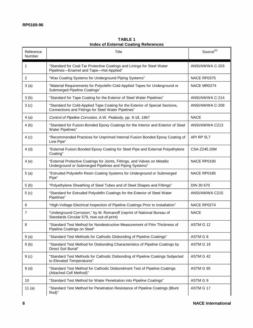
5.1.3.1 Table 1 is a general listing of all externalcoating references used, giving titles and spon-soring sources. In this table, each reference isgiven a reference number for convenient usethereafter.
5.1.3.2 Table 2 is a listing of types of externalcoating systems, showing the appropriatereferences for material specifications and recom-mended practices for application.
5.1.3.3 Table 3 is a grouping of references forgeneral use during installation and inspection,regardless of coating type.
5.1.3.4 Table 4 is a list of external coatingsystem characteristics related to environmentalconditions containing suggested laboratory testreferences for various properties.
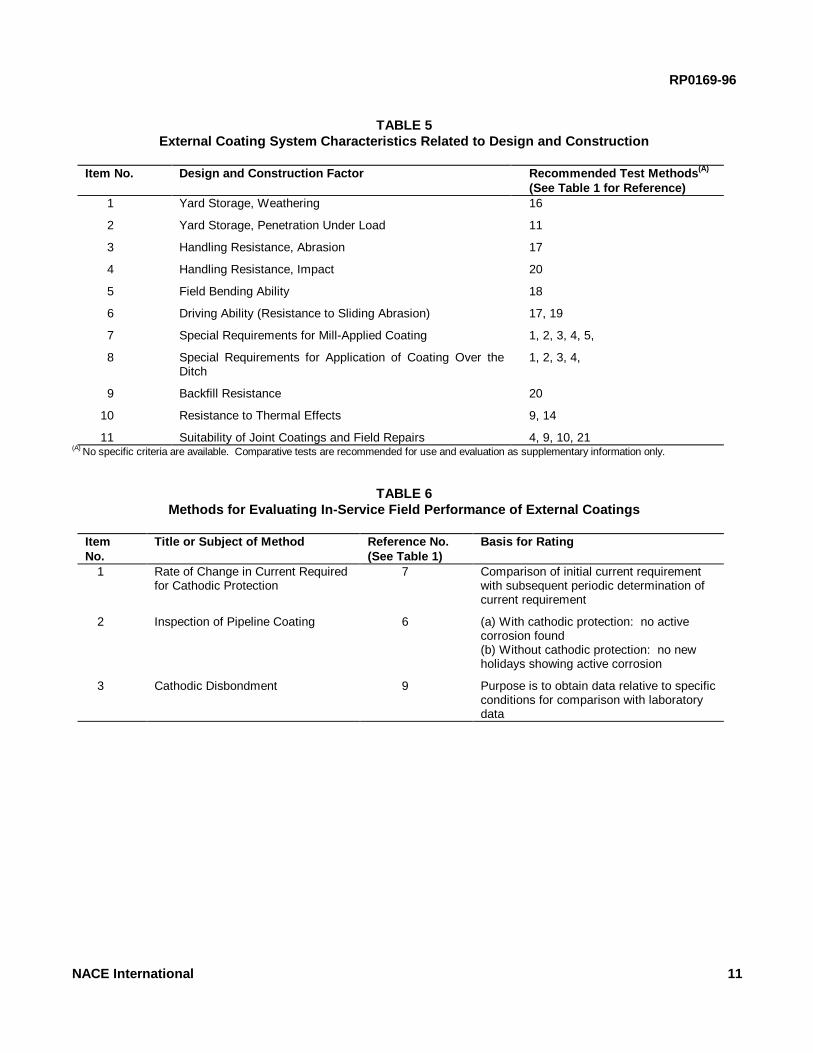
5.1.3.5 Table 5 is a list of external coatingsystem characteristics related to design andconstruction, with recommended laboratory testsfor evaluating these properties.
5.1.3.6 Table 6 lists the references that areuseful in field evaluation of external coatingsystems after the pipeline has been installed.
5.2 Storage, Handling, Inspection, and Installation
5.2.1 Storage and Handling
5.2.1.1 Coated pipe to be stored should beprotected internally and externally from atmos-pheric corrosion and coating deterioration.
5.2.1.2 Damage to coating can be minimized bycareful handling and by using proper pads and
7
slings.
RP0169-96
8 NACE International
TABLE 1Index of External Coating References
ReferenceNumber
Title Source(A)
1 “Standard for Coal-Tar Protective Coatings and Linings for Steel WaterPipelines—Enamel and Tape—Hot-Applied”
ANSI/AWWA C-203
2 “Wax Coating Systems for Underground Piping Systems” NACE RP0375
3 (a) “Material Requirements for Polyolefin Cold-Applied Tapes for Underground orSubmerged Pipeline Coatings”
NACE MR0274
3 (b) “Standard for Tape Coating for the Exterior of Steel Water Pipelines” ANSI/AWWA C-214
3 (c) “Standard for Cold-Applied Tape Coating for the Exterior of Special Sections,Connections and Fittings for Steel Water Pipelines”
ANSI/AWWA C-209
4 (a) Control of Pipeline Corrosion, A.W. Peabody, pp. 9-18, 1967 NACE
4 (b) “Standard for Fusion-Bonded Epoxy Coatings for the Interior and Exterior of SteelWater Pipelines”
ANSI/AWWA C213
4 (c) “Recommended Practices for Unprimed Internal Fusion Bonded Epoxy Coating ofLine Pipe”
API RP 5L7
4 (d) “External Fusion Bonded Epoxy Coating for Steel Pipe and External PolyethyleneCoating”
CSA-Z245.20M
4 (e) “External Protective Coatings for Joints, Fittings, and Valves on MetallicUnderground or Submerged Pipelines and Piping Systems”
NACE RP0190
5 (a) “Extruded Polyolefin Resin Coating Systems for Underground or SubmergedPipe”
NACE RP0185
5 (b) “Polyethylene Sheathing of Steel Tubes and of Steel Shapes and Fittings” DIN 30 670
5 (c) “Standard for Extruded Polyolefin Coatings for the Exterior of Steel WaterPipelines”
ANSI/AWWA C215
6 “High-Voltage Electrical Inspection of Pipeline Coatings Prior to Installation” NACE RP0274
7 “Underground Corrosion,” by M. Romanoff (reprint of National Bureau ofStandards Circular 579, now out-of-print)
NACE
8 “Standard Test Method for Nondestructive Measurement of Film Thickness ofPipeline Coatings on Steel”
ASTM G 12
9 (a) “Standard Test Methods for Cathodic Disbonding of Pipeline Coatings” ASTM G 8
9 (b) “Standard Test Method for Disbonding Characteristics of Pipeline Coatings byDirect Soil Burial”
ASTM G 19
9 (c) “Standard Test Methods for Cathodic Disbonding of Pipeline Coatings Subjectedto Elevated Temperatures”
ASTM G 42
9 (d) “Standard Test Method for Cathodic Disbondment Test of Pipeline Coatings(Attached Cell Method)”
ASTM G 95
10 “Standard Test Method for Water Penetration into Pipeline Coatings” ASTM G 9
11 (a) “Standard Test Method for Penetration Resistance of Pipeline Coatings (BluntRod)”
ASTM G 17

RP0169-96
11 (b) “Standard Test Method for Rubber Property-Durometer Hardness” ASTM D 2240
12 “Test Method for Shrinkage Factors of Soils by the Mercury Method” ASTM D 427
13 (a) “Standard Practice for Evaluating the Resistance of Plastics to ChemicalReagents”
ASTM D 543
13 (b) “Test Method for Resistance of Plastics to Chemical Reagents,” Federal TestStandard No. 406A, Method 7011
General ServicesAdministration
13 (c) “Standard Test Method for Chemical Resistance of Pipeline Coatings” ASTM G 20
14 (a) “Standard Test Method for Thermal Endurance of Rigid Electrical InsulatingMaterials”
ASTM D 2304
14 (b) “Standard Practice for Determining the Effect of Overbaking on OrganicCoatings”
ASTM D 2454
14 (c) “Standard Test Methods for Evaluating Coatings for High Temperature Service” ASTM D 2485
15 (a) “Standard Practice for Determining Resistance of Synthetic Polymeric Materialsto Fungi”
ASTM G 21
15 (b) “Test Method for Mildew Resistance of Plastics by Mixed Culture Method,” AgarMedium, Federal Test Standard No. 406A, Method 6091, January 1982
General ServicesAdministration
16 “Standard Test Method for Effects of Outdoor Weathering on Pipeline Coatings” ASTM G 11
17 “Standard Test Method for Abrasion Resistance of Pipeline Coatings” ASTM G 6
18 “Standard Test Method for Specific Bendability of Pipeline Coatings” ASTM G 10
19 “Standard Test Method for Adhesion of Organic Coatings by Scrape Adhesion” ASTM D 2197
20 (a) “Standard Test Method for Impact Resistance of Pipeline Coatings (LimestoneDrop Test)”
ASTM G 13
20 (b) “Standard Test Method for Impact Resistance of Pipeline Coatings (FallingWeight Test)”
ASTM G 14
21 (a) “Standard Test Method for Joints, Fittings, and Patches in Coated Pipelines” ASTM G 18
21 (b) “Standard Test Method for Evaluating Pipeline Coating Patch Materials” ASTM G 55
____________________________(A) Addresses of Sources:ASTM, 100 Barr Harbor Dr., West Conshohocken, PA 19428-2959. Telephone (610)832-9585.American Petroleum Institute (API), 1220 L St. NW, Washington, DC 20005. Telephone (202)682-8000.American Water Works Association (AWWA), 6666 West Quincy Ave., Denver, CO 80235. Telephone (303)794-7711.National Association of Pipe Coating Applicators (NAPCA), Commercial National Bank Bldg., 333 Texas St., Suite 800, Shreveport, LA 71101-3673. Telephone (318)227-2769.General Services Administration, Business Service Center, Washington, DC 20025. Telephone (202)472-2205.NACE International, P.O. Box 218340, Houston, TX 77218-8340. Telephone (281)492-0535.U.S. Government Printing Office, Washington, DC 20420. Telephone (202)783-3238.Canadian Standards Association (CSA), 178 Rexdale Blvd., Toronto, Ontario, Canada M9W 1R3. Telephone (416)747-4000.Deutsches Institut fur Normung (DIN), Postfach 1107, D-1000 Berlin 30, Germany.
NACE International 9

RP0169-96
TABLE 2Generic External Coating Systems With Material Requirements
and Recommended Practices for Application (A)
Item No. Generic External Coating System Reference No.(See Table 1)
1 Coal Tar 1
2 Wax 2
3 Prefabricated Films 3
4 Fusion-Bonded Epoxy Coatings 4
5 Polyolefin Coatings 5(A) NOTE: Many other references are available and this table is not comprehensive. Listing does not constitute endorsement of any externalcoating system in preference to another. Omission of a system may be due to unavailability of reference standards or lack of data.
TABLE 3References for General Use in the Installation and Inspection
of External Coating Systems for Underground Piping
Item No. Reference Reference No.(See Table 1)
1 Application of Organic PipelineCoatings
1, 2, 4
2 Film Thickness of Pipeline Coatings 8
3 Inspection of Pipeline Coatings 6
TABLE 4External Coating System Characteristics Relative to Environmental Conditions (A)
Item No. Environmental Factor Recommended TestMethods (B)
(See Table 1 for Reference)1 General underground exposure with or without cathodic protection 4, 9
2 Resistance to water penetration and its effect on choice of coatingthickness
10
3 Resistance to penetration by stones in backfill 11, 20
4 Soil stress 7, 12
5 Resistance to specific liquid not normally encountered in virginsoil
13
6 Resistance to thermal effects 14
7 Suitability of supplementary materials for joint coating and fieldrepairs
9, 10, 21
8 Resistance to microorganisms 15(A) NOTE: Apply only those factors pertinent to the installation.(B) No specific criteria are available. Comparative tests are recommended for use and evaluation as supplementary information only.
10 NACE International
RP0169-96
TABLE 5External Coating System Characteristics Related to Design and Construction
Item No. Design and Construction Factor Recommended Test Methods (A)
(See Table 1 for Reference)1 Yard Storage, Weathering 16
2 Yard Storage, Penetration Under Load 11
3 Handling Resistance, Abrasion 17
4 Handling Resistance, Impact 20
5 Field Bending Ability 18
6 Driving Ability (Resistance to Sliding Abrasion) 17, 19
7 Special Requirements for Mill-Applied Coating 1, 2, 3, 4, 5,
8 Special Requirements for Application of Coating Over theDitch
1, 2, 3, 4,
9 Backfill Resistance 20
10 Resistance to Thermal Effects 9, 14
11 Suitability of Joint Coatings and Field Repairs 4, 9, 10, 21(A) No specific criteria are available. Comparative tests are recommended for use and evaluation as supplementary information only.
TABLE 6Methods for Evaluating In-Service Field Performance of External Coatings
ItemNo.
Title or Subject of Method Reference No.(See Table 1)
Basis for Rating
1 Rate of Change in Current Requiredfor Cathodic Protection
7 Comparison of initial current requirementwith subsequent periodic determination ofcurrent requirement
2 Inspection of Pipeline Coating 6 (a) With cathodic protection: no activecorrosion found(b) Without cathodic protection: no newholidays showing active corrosion
3 Cathodic Disbondment 9 Purpose is to obtain data relative to specificconditions for comparison with laboratorydata
NACE International 11

RP0169-96
5.2.2 Inspection
5.2.2.1 Qualified personnel should keep everyphase of the coating operation and pipinginstallation under surveillance.
5.2.2.2 Surface preparation, primer application,coating thickness, temperature, bonding, andother specific requirements should be checkedperiodically, using suitable test procedures, forconformance to specifications.
5.2.2.3 The use of holiday detectors is recom-mended to detect coating flaws that would not beobserved visually. The holiday detector shouldbe operated in accordance with the manu-facturer's instructions and at a voltage levelappropriate to the electrical characteristics of thecoating system.
5.2.3 Installation
5.2.3.1 Joints, fittings, and tie-ins must becoated with a material compatible with theexisting coating.
5.2.3.2 Coating defects should be repaired.
5.2.3.3 Materials used to repair coatings mustbe compatible with the existing pipe coating.
5.2.3.4 The ditch bottom should be graded andfree of rock or other foreign matter that coulddamage the external coating or cause electricalshielding. Under difficult conditions, considera-tion should be given to padding the pipe or theditch bottom.
5.2.3.5 Pipe should be lowered carefully into theditch to avoid external coating damage.
5.2.3.6 Care should be taken when backfilling sothat rocks and debris do not strike and damagethe pipe coating.
5.2.3.7 Care shall be exercised when usingmaterials such as loose wrappers, noncon-ducting urethane foam, and rock shield aroundpipelines as protection against physical damageor for other purposes, because these materialsmay create an electrical shielding effect thatwould be detrimental to the effectiveness ofcathodic protection.
5.2.3.8 Where a pipeline comes above ground,it must be cleaned and externally coated, orjacketed with a suitable material, for the preven-tion of atmospheric corrosion.
12
5.3 Methods for Evaluating External Coating Systems
5.3.1 Established Systems Proven by SuccessfulUse
5.3.1.1 Visual and electrical inspection ofin-service pipeline coatings should be used toevaluate the performance of an external coatingsystem. These inspections can be conductedwherever the pipeline is excavated or at bellholes made for inspection purposes.
5.3.2 Established or Modified Systems for NewEnvironments
5.3.2.1 This method is intended for use whereexternal coating systems will continue to be usedand are qualified under Paragraph 5.3.1, butwhere application will be extended to newenvironments or where it is desired to revise asystem to make use of new developments.
5.3.2.1.1 The use of applicable materialrequirements, material specifications, stan-dards, and recommended practices forapplication, as given in Table 2, is recom-mended.
5.3.2.1.2 The use of applicable referencesin Table 3 is recommended unless pre-viously covered in applicable references inTable 2.
5.3.3 New External Coating System Qualification
5.3.3.1 The purpose of this method is to qualifya new external coating material by subjecting itto laboratory tests appropriate for the intendedservice. After laboratory tests have been con-ducted and indicate that the external coatingsystem appears to be suitable, application andinstallation are conducted in accordance withrecommended practices. In-service field per-formance tests are made to confirm the successof the previous steps. The steps of the methodare (1) laboratory tests, (2) application underrecommended practices, (3) installation underrecommended practices, and (4) in-service fieldperformance tests. If good results are obtainedafter five years, only Steps 2 and 3 are requiredthereafter.
5.3.3.1.1 Applicable sections of Tables 4and 5 are recommended for the initiallaboratory test methods.
5.3.3.1.2 Applicable sections of Tables 2and 3 are recommended for conditional useduring Steps 2 and 3.
5.3.3.1.3 During a period of five years or
NACE International
more, the use of the evaluation methods

RP0169-96
N
6
given in Table 6, Item 1 or 2 is recom-mended. The test method in Item 3 may beused as a supplementary means forobtaining data for correlation with laboratorytests.
5.3.4 Method for Evaluating an External CoatingSystem by In-Service Field Performance Only
5.3.4.1 The purpose of this method is to qualifyan external coating system where none of the
ACE International
______________
.2 Criteria
first three methods given in Paragraph 5.3 havebeen or will be used. It is intended that thismethod should be limited to minor pilot instal-lations.
5.3.4.1.1 The use of at least one of the firsttwo methods given in Table 6 is recom-mended on the basis of at least oneinvestigation per year for five consecutiveyears.
______________
___________________________________________Section 6: Criteria and Other Considerations
P for Cathodic6.1 Introduction
6.1.1 This section lists criteria and other consider-ations for cathodic protection that will indicate, whenused either separately or in combination, whetheradequate cathodic protection of a metallic pipingsystem has been achieved (see also Section 1,Paragraphs 1.2 and 1.4).
6.1.2 The effectiveness of cathodic protection orother external corrosion control measures can beconfirmed by visual observation, by measurementsof pipe wall thickness, or by use of internal inspectiondevices. Because such methods sometimes are notpractical, meeting any criterion or combination ofcriteria in this section is evidence that adequatecathodic protection has been achieved. When exca-vations are made for any purpose, the pipe should beinspected for evidence of corrosion and/or coatingcondition.
6.1.3 The criteria in this section have beendeveloped through laboratory experiments and/orverified by evaluating data obtained from success-fully operated cathodic protection systems. Situa-tions may exist where a single criterion for evaluatingthe effectiveness of cathodic protection may not besatisfactory for all conditions. Often a combinationof criteria is needed for a single structure.
6.1.4 Sound engineering practices shall be used todetermine the methods and frequency of testingrequired to satisfy these criteria.
6.1.5 Corrosion leak history is valuable in assessingthe effectiveness of cathodic protection. Corrosionleak history by itself, however, shall not be used todetermine whether adequate levels of cathodicprotection have been achieved unless it is impracticalto make electrical surveys.
rotection
6.2.1 It is not intended that persons responsible forexternal corrosion control be limited to the criterialisted below. Criteria that have been successfullyapplied on existing piping systems can continue to beused on those piping systems. Any other criteriaused must achieve corrosion control comparable tothat attained with the criteria herein.
6.2.2 Steel and Cast Iron Piping
6.2.2.1 External corrosion control can beachieved at various levels of cathodic polari-zation depending on the environmental con-ditions. However, in the absence of specific datathat demonstrate that adequate cathodic pro-tection has been achieved, one or more of thefollowing shall apply:
6.2.2.1.1 A negative (cathodic) potential ofat least 850 mV with the cathodic protectionapplied. This potential is measured withrespect to a saturated copper/copper sulfatereference electrode contacting the electro-lyte. Voltage drops other than those acrossthe structure-to-electrolyte boundary mustbe considered for valid interpretation of thisvoltage measurement.
NOTE: Consideration is understood tomean the application of sound engineeringpractice in determining the significance ofvoltage drops by methods such as:
6.2.2.1.1.1 Measuring or calculating the voltage drop(s);
6.2.2.1.1.2 Reviewing the historical performance of the cathodic protection system;
6.2.2.1.1.3 Evaluating the physical andelectrical characteristics of the pipe and
13
its environment; and

RP0169-96
14
6.2.2.1.1.4 Determining whether or not there is physical evidence of corrosion.
6.2.2.1.2 A negative polarized potential (seedefinition in Section 2) of at least 850 mVrelative to a saturated copper/copper sulfatereference electrode.
6.2.2.1.3 A minimum of 100 mV of cathodicpolarization between the structure surfaceand a stable reference electrode contactingthe electrolyte. The formation or decay ofpolarization can be measured to satisfy thiscriterion.
6.2.2.2 Special Conditions
6.2.2.2.1 On bare or ineffectively coatedpipelines where long-line corrosion activityis of primary concern, the measurement of anet protective current at predeterminedcurrent discharge points from the electrolyteto the pipe surface, as measured by anearth current technique, may be sufficient.
6.2.2.2.2 In some situations, such as thepresence of sulfides, bacteria, elevated tem-peratures, acid environments, and dissimilarmetals, the criteria in Paragraph 6.2.2.1may not be sufficient.
6.2.2.2.3 When a pipeline is encased inconcrete or buried in dry or aerated high-resistivity soil, values less negative than thecriteria listed in Paragraph 6.2.2.1 may besufficient.
6.2.2.3 PRECAUTIONARY NOTES
6.2.2.3.1 The earth current technique isoften meaningless in multiple pipe rights-of-way, in high-resistivity surface soil, fordeeply buried pipe, in stray-current areas, orwhere local corrosion cell action pre-dominates.
6.2.2.3.2 Caution is advised against usingpolarized potentials less negative than -850mV for cathodic protection of pipelines whenoperating pressures and conditions areconducive to stress corrosion cracking (seereferences on stress corrosion cracking atthe end of this section).
6.2.2.3.3 The use of excessive polarizedpotentials on externally coated pipelines
should be avoided to minimize cathodicdisbondment of the coating.
6.2.2.3.4 Polarized potentials that result inexcessive generation of hydrogen should beavoided on all metals, particularly higherstrength steel, certain grades of stainlesssteel, titanium, aluminum alloys, and pre-stressed concrete pipe.
6.2.3 Aluminum Piping
6.2.3.1 The following criterion shall apply: aminimum of 100 mV of cathodic polarizationbetween the structure surface and a stablereference electrode contacting the electrolyte.The formation or decay of this polarization canbe used in this criterion.
6.2.3.2 PRECAUTIONARY NOTES
6.2.3.2.1 Excessive Voltages: Notwith-standing the minimum criterion in Section6.2.3.1, if aluminum is cathodically pro-tected at voltages more negative than -1200mV measured between the pipe surface anda saturated copper/copper sulfate referenceelectrode contacting the electrolyte andcompensation is made for the voltage dropsother than those across the pipe-electrolyteboundary, it may suffer corrosion as theresult of the buildup of alkali on the metalsurface. A polarized potential more nega-tive than -1,200 mV should not be usedunless previous test results indicate that noappreciable corrosion will occur in theparticular environment.
6.2.3.2.2 Alkaline Conditions: Aluminummay suffer from corrosion under high-pHconditions and application of cathodicprotection tends to increase the pH at themetal surface. Therefore, careful investiga-tion or testing should be made beforeapplying cathodic protection to stop pittingattack on aluminum in environments with anatural pH in excess of 8.0.
6.2.4 Copper Piping
6.2.4.1 The following criterion shall apply: aminimum of 100 mV of cathodic polarizationbetween the structure surface and a stablereference electrode contacting the electrolyte.The formation or decay of this polarization canbe used in this criterion.
NACE International

RP0169-96
6.2.5 Dissimilar Metal Piping
6.2.5.1 A negative voltage between all pipesurfaces and a stable reference electrodecontacting the electrolyte equal to that requiredfor the protection of the most anodic metalshould be maintained.
6.2.5.2 PRECAUTIONARY NOTE
6.2.5.2.1 Amphoteric materials that couldbe damaged by high alkalinity created bycathodic protection should be electricallyisolated and separately protected.
6.3 Other Considerations
6.3.1 Methods for determining voltage drop(s) shallbe selected and applied using sound engineeringpractices. Once determined, the voltage drop(s) maybe used for correcting future measurements at thesame location, providing conditions such as pipe andcathodic protection system operating conditions, soilcharacteristics, and external coating quality remainsimilar. (Note: Placing the reference electrode nextto the pipe surface may not be at the pipe-electrolyteinterface. A reference electrode placed at anexternally coated pipe surface may not significantlyreduce soil voltage drop in the measurement if thenearest coating holiday is remote from the referenceelectrode location.)
6.3.2 When it is impractical or considered unneces-sary to disconnect all current sources to correct forvoltage drop(s) in the structure-to-electrolyte poten-tial measurements, sound engineering practicesshould be used to ensure that adequate cathodicprotection has been achieved.
6.3.3 Where feasible and practicable, in-lineinspection of pipelines may be helpful in determiningthe presence or absence of pitting corrosion damage.Absence of external corrosion damage or the halting
NACE International
August, 1973, pp. 13-14.
of its growth may indicate adequate externalcorrosion control. The in-line inspection technique,however, may not be capable of detecting all types ofexternal corrosion damage, has limitations in itsaccuracy, and may report as anomalies items thatare not external corrosion. For example, longitudinalseam corrosion and general corrosion may not bereadily detected by in-line inspection. Also, possiblethickness variations, dents, gouges, and externalferrous objects may be detected as corrosion. Theappropriate use of in-line inspection must becarefully considered.
6.3.4 Situations involving stray currents and strayelectrical gradients may exist that require specialanalysis. For additional information, see Section 9,“Control of Interference Currents.”
6.4 Alternative Reference Electrodes
6.4.1 Other standard reference electrodes may besubstituted for the saturated copper/copper sulfatereference electrode. Two commonly used referenceelectrodes are listed below along with their voltageequivalent (at 25°C [77°F]) to -850 mV referred to asaturated copper/copper sulfate reference electrode:
6.4.1.1 Saturated KCl calomel referenceelectrode: -780 mV; and
6.4.1.2 Saturated silver/silver chloride referenceelectrode used in 25 ohm-cm seawater: -800mV.
6.4.2 In addition to these standard reference elec-trodes, an alternative metallic material or structuremay be used in place of the saturated copper/coppersulfate reference electrode if the stability of itselectrode potential is ensured and if its voltageequivalent referred to a saturated copper/coppersulfate reference electrode is established.
Bibliography for Section 6
Criteria for Copper
Schwerdtfeger, W.J. “Criteria for Cathodic Protection—Highly Resistant Copper Deteriorates in Severely Corrosive Soil.” Materials Protection 57, 9 (1968): p. 43.
Criteria for Aluminum
CP1021. “Code of Practice for Cathodic Protection.” London, England: British Standards Institution,
DIN30 676 (German Standard). “Design and Application of Cathodic Protection of External Surfaces.” Berlin, Germany: Deutsches Institut fur Normung, October, 1985.
NACE Publication 2M363. “Recommended Practice for Cathodic Protection of Aluminum Pipe Buried in Soil or Immersed in Water.” Materials Performance 2,10 (1963): p. 106.
Schwerdtfeger, W.J. “Effects of Cathodic Current on the
15
Corrosion of An Aluminum Alloy.” National Bureau

RP0169-96
of Standards Journal of Research 68c (Oct.-Dec. 1964): p. 283.
Criteria for Steel and Cast Iron
Doremus, E.P., and T.L. Canfield. “The Surface PotentialSurvey Can Detect Pipeline Corrosion Damage.” Materials Protection 6, 9 (1967): p. 33.
Ewing, S.P. “Potential Measurements for Determination of Cathodic Protection Requirements.” Corrosion 7, 12 (1951): p. 410.
Haycock, E.W. “Current Requirements for Cathodic Protection of Oil Well Casing.” Corrosion 13, 11 (1957): p. 767.
Kuhn, R.C. “Cathodic Protection of Underground Pipelines Against Soil Corrosion.” American Petroleum Institute Proceedings IV, 14 (1953): p. 153.
McCollum, B., and K.H. Logan. National Bureau of Standards Technical Paper No. 351, 1927.
Romanoff, M. Underground Corrosion. Houston, TX: NACE, 1989.
Pearson, J.M. Contributions of J.M. Pearson to Mitigationof Underground Corrosion—A Collection of Papers. Houston, TX: NACE Publication 56-12.
Pearson, J.M. “Electrical Instruments and Measurement in Cathodic Protection.” Corrosion 3, 11 (1947): p. 549.
Pearson, J.M. “Null Methods Applied to Corrosion Measurements.” Transactions of the ElectrochemicalSociety 81 (1942): p. 485.
Schwerdtfeger, W.J., and O.N. McDorman. “Potential and Current Requirements for the Cathodic Protection of Steel in Soils.” Corrosion 8, 11 (1952): p. 391.
Sudrabin, L.P., and F.W. Ringer. “Some Observations on Cathodic Protection Criteria.” Corrosion 13, 5 (1957) p. 351t. Discussion on this paper Corrosion13, 12 (1957): p. 835t.
Additional References
Barlo, T.J., and W.E. Berry. “A Reassessment of the -0.85 V and 100 mV Polarization Criteria for Cathodic Protection of Steel Buried in Soils. Ninth International Congress on Metallic Corrosion 4, (1984): June 7. National Research Council of
16
Canada.
Barlo, T.J., and W.E. Berry. “An Assessment of the Current Criteria for Cathodic Protection of Buried Steel Pipes.” Materials Performance 23, 9 (1984).
Barlo, T.J., and R.R. Fessler. “Interpretation of True Pipe-to-Soil Potentials on Coated Pipelines with Holidays.”CORROSION/83, paper no. 292. Houston, TX: NACE, 1983.
Barlo, T.J., and R.R. Fessler. “Investigation of Techniques to Determine the True Pipe-to-Soil Potential of a Buried Pipeline.” AGA Project PR-3-93, 1979 Annual Report, May, 1980.
Cathodic Protection Criteria—A Literature Survey. Houston, TX: NACE, 1989.
Comeaux, R.V. “The Role of Oxygen in Corrosion and Cathodic Protection.” Corrosion 8, 9 (1952): pp. 305-309.
Compton, K.G. “Criteria and Their Application for Cathodic Protection of Underground Structures.” Materials Protection 4, 8 (1965): pp. 93-96.
Dabkowski, J. “Assessing the Cathodic Protection Levelsof Well Casings.” AGA Project 151-106, Final Report, January 1983: pp. 3-92.
Dexter, S.C., L.N. Moettus, and K.E. Lucas. “On the Mechanism of Cathodic Protection.” Corrosion 41, 10 (1985).
“Field Testing the Criteria for Cathodic Protection.” AGA Interim Report PR-151-163, December, 1987.
Fischer, K.P. “Cathodic Protection in Saline Mud Containing Sulfate Reducing Bacteria.” Materials Performance 20, 10 (1981): pp. 41-46.
Gummow, R.A. “Cathodic Protection Criteria—A Critical Review of NACE Standard RP0169.” Materials Performance 25, 9 (1986): pp. 9-16.
Hoey, G.R., and M. Cohen. “Cathodic Protection of Iron in the Temperature Range 25-92 C.” Corrosion 14, 4 (1958): pp. 200t-202t.
Holler, H.D. “Studies on Galvanic Couples II-Some Potential-Current Relations in Galvanic Corrosion.” Journal of the Electrochemical Society September (1950): pp. 277-282.
Howell, R.P. “Potential Measurements in Cathodic Protection Designs.” Corrosion 8 (1952).
Jones, D. “Electrochemical Fundamentals of Cathodic
NACE International
Protection.” CORROSION/87, paper no. 317. Houston, TX: NACE, 1987.

RP0169-96
Kasahara, K., T. Sato, and H. Adachi. “Results of Polarization Potential and Current Density Surveys on Existing Buried Pipelines.” Materials Performance19, 9 (1980): pp. 45-51.
Kehn, G.R., and E.J. Wilhelm. “Current Requirements forthe Cathodic Protection of Steel in Dilute Aqueous Solutions.” Corrosion 7, 5 (1951): pp. 156-160.
Koybayaski, T. “Effect of Environmental Factors on the Protective Potential of Steel.” Proceedings of the Fifth International Congress on Metallic Corrosion. Houston, TX: NACE, 1980.
Krivian, L. “Application of the Theory of Cathodic Protection to Practical Corrosion Systems.” British Corrosion Journal, 19, 1 (1984).
Kuhn, R.J. “Cathodic Protection on Texas Gas Systems.”AGA Annual Conference. Detroit, MI: April 1950.
Lattin, B.C. “The Errors of Your Ways (Fourteen Pitfalls for Corrosion Engineers and Technicians to Avoid).” Materials Performance, 20, 3 (1981): p. 30.
Logan, K.H. “Comparison of Cathodic Protection Test Methods.” Corrosion, 10, 7 (1959).
Logan, K.H. “Underground Corrosion.” National Bureau of Standards Circular C450, November, 1945, pp. 249-278.
Logan, K.H. “The Determination of the Current Required for Cathodic Protection.” National Bureau of Standards Soil Corrosion Conference, March, 1943.
Martin, B.A. “Cathodic Protection: The Ohmic Component of Potential Measurements—Laboratory Determination with a Polarization Probe in Aqueous Environments.” Materials Performance 20, 1 (1981): p. 52.
Martin, B.A., and J.A. Huckson. “New Developments in Interference Testing.” Industrial Corrosion 4, 6 (1986): pp. 26-31.
Mears and Brown. “A Theory of Cathodic Protection.” Transactions of the Electrochemical Society 74 (1938): p. 527.
Morgan, J. Cathodic Protection. Houston, TX: NACE, 1987.
NACE Technical Committee T-2C Report. “Criteria for Adequate Cathodic Protection of Coated, Buried, or Submerged Steel Pipe Lines and Similar Steel Structures.” Corrosion 14,13 (1958): p. 561t.
NACE International
Pearson, J.M. “Concepts and Methods of Cathodic Protection.” The Petroleum Engineer 15, 6 (1944): p.218; and 15, 7 (1944): p. 199.
Pourbaix, M. Atlas of Electrochemical Equilibria in Aqueous Solutions. Houston, TX: NACE, 1974, p. 319.
Prinz, W. “Close Interval Potential Survey of Buried Pipelines, Methods and Experience.” UK Corrosion '86, p. 67.
Riordan, M.A. “The Electrical Survey—What It Won't Do,” Materials Performance 17, 11 (1978): pp. 38-41.
Riordan, M.A., and R.P. Sterk. “Well Casing as an Electrochemical Network in Cathodic Protection Design.” Materials Performance 2, 7 (1963): pp. 58-68.
Schaschl, E., and G.A. Marsh. “Placement of Reference Electrode and Impressed Current Anode Effect on Cathodic Protection of Steel in a Long Cell.” Materials Performance 13, 6 (1974): pp. 9-11.
Stern, M. “Fundamentals of Electrode Processes in Corrosion.” Corrosion 13, 11 (1957): pp. 775t-782t.
Task Group E4-2. “State-of-the-Art Report, Specialized Surveys for Buried Pipelines.” Corrosion Control Engineering Joint Venture, March, 1987: p. 22.
Thompson, N.G., and T.J. Barlo. “Fundamental Process of Cathodically Protecting Steel Pipelines.” International Gas Research Conference, 1983.
Toncre, A.C. “A Review of Cathodic Protection Criteria.” Proceeding of Sixth European Congress on Metallic Corrosion. London, England: September, (1977): pp. 365-372.
Van Nouhuys, H.C. “Cathodic Protection and High Resistivity Soil.” Corrosion 9 (1953): pp. 448-458.
Van Nouhuys, H.C. “Cathodic Protection and High Resistivity Soil—A Sequel.” Corrosion 14, 12 (1958):pp. 583-587.
Von Baekmann, W., A. Ballest, and W. Prinz. “New Development in Measuring the Effectiveness of Cathodic Protection.” Corrosion Australasia,February, 1983.
Von Baekmann, W., and W. Schwenk. Handbook of Cathodic Protection. Portellis Press, 1975, Chapter 2.
17
RP0169-96
Webster, R.D. “Compensating for the IR Drop Component in Pipe-to-Soil Potential Measurements.”Materials Performance 26, 10 (1987): pp. 38-41.
Wyatt, B.S., K.C. Lax. “Close Interval Overline Polarized Potential Surveys of Buried Pipelines.” UK CorrosionConference, 1985.
Stress Corrosion Cracking
Barlo, T.J., et al. “An Assessment of the Criteria for Cathodic Protection of Buried Pipelines.” American Gas Association Final Report, Project PR-3-129, 1983.
Barlo, T.J., et al. “Controlling Stress-Corrosion Cracking by Cathodic Protection.” American Gas Association Annual Report, Project-3-164, 1984.
Parkins, R.N., et al. “Hydrogen Gas Evolution From Cathodically Protected Surfaces.” Corrosion 41
18
(1985): pp. 389-397.
_________________________________
____________________________(2)National Electrical Manufacturers Association (NEMA), 2101 L St., N(3)National Fire Protection Association, Batterymarch Park, Quincy, MA
Parkins, R.N., and R.R. Fessler. “Stress Corrosion Cracking of High Pressure Gas Transmission Pipelines.” Materials in Engineering Applications 1, pp. 80-96.
Parkins, R.N., and R.R. Fessler. “Line Pipe Stress Corrosion Cracking—Mechanisms and Remedies.” CORROSION/86 paper no. 320. Houston, TX: NACE, 1986.
Parkins, R.N., A.J. Markworth, and J.H. Holbrook. “Hydrogen Gas Evolution From Cathodically Protected Pipeline Steel Surfaces Exposed to Chloride-Sulfate Solutions.” Corrosion 44 (1988): pp.572-580.
McCaffrey, W.R. “Effect of Overprotection on Pipeline Coatings.” Materials Protection and Performance 12,2 (1973): p. 10.
PR-15-427. “An Assessment of Stress Corrosion Cracking (SCC) Research for Line Pipe Steels.”
American Gas Association, 1985.______________________________________
Section 7: Design of Cathodic Protection Systems
7.1 Introduction
7.1.1 This section recommends procedures fordesigning cathodic protection systems that willprovide effective external corrosion control bysatisfying one or more of the criteria listed in Section6 and exhibiting maximum reliability over theintended operating life of the systems.
7.1.2 In the design of a cathodic protection system,the following should be considered:
7.1.2.1 Recognition of hazardous conditionsprevailing at the proposed installation site(s) andthe selection and specification of materials andinstallation practices that will ensure safeinstallation and operation.
7.1.2.2 Specification of materials and instal-lation practices to conform to the latest editionsof applicable codes, National Electrical Manu-facturers Association (NEMA)(2) standards,National Electrical Code (NEC),(3) appropriateinternational standards, and NACE standards.
W, W 022
7.1.2.3 Selection and specification of materialsand installation practices that will ensuredependable and economical operation through-out the intended operating life.
7.1.2.4 Selection of locations for proposedinstallations to minimize currents or earthpotential gradients, which can cause detrimentaleffects on foreign buried or submerged metallicstructures.
7.1.2.5 Cooperative investigations to determinemutually satisfactory solution(s) of interferenceproblems (see Section 9).
7.1.2.6 Special consideration should be given tothe presence of sulfides, bacteria, disbondedcoatings, thermal insulating coatings, elevatedtemperatures, shielding, acid environments, anddissimilar metals.
7.1.2.7 Excessive levels of cathodic protectionthat can cause external coating disbondmentand possible damage to high-strength steels as
NACE International
ashington, DC 20037.69.

RP0169-96
NACE International 19
a result of hydrogen evolution should beavoided.
7.1.2.8 Where amphoteric metals are involved,care should be taken so that high-pH conditionsare not established that could cause cathodiccorrosion of the metal.
7.2 Major objectives of cathodic protection systemdesign include the following:
7.2.1 To provide sufficient current to the structure tobe protected and distribute this current so that theselected criteria for cathodic protection are effectivelyattained;
7.2.2 To minimize the interference currents onneighboring underground structures (see Section 9);
7.2.3 To provide a design life of the anode systemcommensurate with the required life of the protectedstructure, or to provide for periodic rehabilitation ofthe anode system;
7.2.4 To provide adequate allowance for anticipatedchanges in current requirements with time;
7.2.5 To install anodes where the possibility ofdisturbance or damage is minimal; and
7.2.6 To provide adequate monitoring facilities totest and evaluate the system performance.
7.3 Information Useful for Design
7.3.1 Useful piping system specifications andinformation include the following:
7.3.1.1 Route maps and atlas sheets;
7.3.1.2 Construction dates;
7.3.1.3 Pipe, fittings, and other appurtenances;
7.3.1.4 External coatings;
7.3.1.5 Casings;
7.3.1.6 Corrosion control test stations;
7.3.1.7 Electrically isolating devices;
7.3.1.8 Electrical bonds; and
7.3.1.9 Aerial, bridge, and underwater cross-ings.
7.3.2 Useful information on piping system siteconditions includes the following:
7.3.2.1 Existing and proposed cathodic protec-tion systems;
7.3.2.2 Possible interference sources (seeSection 9);
7.3.2.3 Special environmental conditions;
7.3.2.4 Neighboring buried metallic structures(including location, ownership, and corrosioncontrol practices);
7.3.2.5 Structure accessibility;
7.3.2.6 Power availability; and
7.3.2.7 Feasibility of electrical isolation fromforeign structures.
7.3.3 Useful information from field surveys,corrosion test data, and operating experienceincludes the following:
7.3.3.1 Protective current requirements to meetapplicable criteria;
7.3.3.2 Electrical resistivity of the electrolyte;
7.3.3.3 Electrical continuity;
7.3.3.4 Electrical isolation;
7.3.3.5 External coating integrity;
7.3.3.6 Cumulative leak history;
7.3.3.7 Interference currents;
7.3.3.8 Deviation from construction specifica-tions; and
7.3.3.9 Other maintenance and operating data.
7.3.4 Field survey work prior to actual application ofcathodic protection is not always required if priorexperience or test data are available to estimatecurrent requirements, electrical resistivities of theelectrolyte, and other design factors.
7.4 Types of Cathodic Protection Systems
7.4.1 Galvanic Anode Systems
7.4.1.1 Galvanic anodes can be made ofmaterials such as alloys of magnesium, zinc, oraluminum. The anodes are connected to thepipe, either individually or in groups. Galvanicanodes are limited in current output by theanode-to-pipe driving voltage and the electrolyteresistivity.

RP0169-96
7.4.2 Impressed Current Anode Systems
7.4.2.1 Impressed current anodes can be ofmaterials such as graphite, high-silicon castiron, lead-silver alloy, precious metals, or steel.They are connected with an insulated cable,either individually or in groups, to the positiveterminal of a direct-current source, such as arectifier or generator. The pipeline is connectedto the negative terminal of the direct-currentsource.
7.5 Considerations influencing selection of the type ofcathodic protection system include the following:
7.5.1 Magnitude of protective current required;
7.5.2 Stray currents causing significant potentialfluctuations between the pipeline and earth that maypreclude the use of galvanic anodes;
7.5.3 Effects of cathodic protection interferencecurrents on adjacent structures that may limit the useof impressed current cathodic protection systems;
7.5.4 Availability of electrical power;
7.5.5 Physical space available, proximity of foreignstructures, easement procurement, surface condi-tions, presence of streets and buildings, rivercrossings, and other construction and maintenanceconcerns.
7.5.6 Future development of the right-of-way areaand future extensions to the pipeline system;
7.5.7 Costs of installation, operation, and main-tenance; and
7.5.8 Electrical resistivity of the environment.
7.6 Factors Influencing Design of Cathodic ProtectionSystems
7.6.1 Various anode materials have different rates ofdeterioration when discharging a given currentdensity from the anode surface in a specificenvironment. Therefore, for a given current output,the anode life will depend on the environment andanode material, as well as the anode weight and thenumber of anodes in the cathodic protection system.Established anode performance data may be used tocalculate the probable deterioration rate.
7.6.2 Data on the dimensions, depth, and con-figuration of the anodes and the electrolyte resistivitymay be used to calculate the resultant resistance toelectrolyte of the anode system. Formulas andgraphs relating to these factors are available in theliterature and from manufacturers.
20
7.6.3 Design of galvanic anode systems shouldconsider anode-to-pipe potential, electrolyte resis-ivity, current output, and in special cases, anodelead-wire resistance. A separate design for eachanode or anode system may not be necessary.
7.6.4 Galvanic anode performance in most soils canbe improved by using special backfill material.Mixtures of gypsum, bentonite, and anhydroussodium sulfate are most commonly used.
7.6.5 The number of impressed current anodesrequired can be reduced and their useful lifelengthened by the use of special backfill around theanodes. The most common materials are coal coke,calcined petroleum coke, and natural or manu-factured graphite.
7.6.6 In the design of an extensive distributed-anodeimpressed current system, the voltage and currentattenuation along the anode-connecting (header)cable should be considered. In such cases, thedesign objective is to optimize anode system length,anode spacing and size, and cable size in order toachieve efficient external corrosion control at theextremities of the protected structure.
7.6.7 Where it is anticipated that entrapment of gasgenerated by anodic reactions could impair the abilityof the impressed current groundbed to deliver therequired current, suitable provisions should be madefor venting the anodes. For the same current outputof the system, an increase in the surface area of thespecial backfill material or an increase in the numberof anodes may reduce gas blockage.
7.6.8 Where it is anticipated that electroosmoticeffects could impair the ability of the impressedcurrent groundbed to deliver the required currentoutput, suitable provisions should be made to ensureadequate soil moisture around the anodes.Increasing the number of impressed current anodesor increasing the surface area of the special backfillmaterials may further reduce the electroosmoticeffect.
7.7 Design Drawings and Specifications
7.7.1 Suitable drawings should be prepared todesignate the overall layout of the piping to beprotected and the location of significant items ofstructure hardware, corrosion control test stations,electrical bonds, electrical isolation devices, andneighboring buried or submerged metallic structures.
7.7.2 Layout drawings should be prepared for eachimpressed current cathodic protection installation,showing the details and location of the componentsof the cathodic protection system with respect to theprotected structure(s) and to major physical land-
NACE International
RP0169-96
N
marks. These drawings should include right-of-wayinformation.
7.7.3 The locations of galvanic anode installationsshould be recorded on drawings or in tabular form,
ACE International
Bibliography fo
__________
th
construction drawings and specifications. The con-
with appropriate notes on anode type, weight,spacing, depth, and backfill.
7.7.4 Specifications should be prepared for allmaterials and installation practices that are to beincorporated in construction of the cathodic pro-tection system.
r Section 7
Anode Resistance Fundamentals and Applications—Classic Papers and Reviews. Houston, TX: NACE, 1986.
Baboian, R., P.F. Drew, and K. Kawate. “Design of Platinum Clad Wire Anodes for Impressed Current Protection.” Materials Performance 23, 9 (1984): pp.31-35.
Collected Papers on Cathodic Protection Current Distribution. Houston, TX: NACE, 1989.
Doremus, G., and J.G. Davis. “Marine Anodes: The Old and New.” Materials Performance 6, 1 (1967): p. 30.
Dwight, H.B. “Calculations for Resistance to Ground.” Electrical Engineering 55 (1936): p. 1319.
George P.F., J.J. Newport, and J.L. Nichols. “A High Potential Magnesium Anode.” Corrosion 12, 12 (1956): p. 627t.
Jacobs, J.A. “A Comparison of Anodes for Impressed Current Systems.” NACE Canadian Region Western Conference, Edmonton, Alberta, Canada, February, 1980.
Kurr, G.W. “Zinc Anodes—Underground Uses for Cathodic Protection and Grounding.” Materials Per-
formance 18, 4 (1979): pp. 34-41.
NACE Publication 2B160. “Use of High Silicon Cast Iron for Anodes.” Corrosion 16, 2 (1960): p. 109.
NACE Publication 2B156. “Final Report on Four Annual Anode Inspections.” Corrosion 12, 1 (1956): p. 63.
Parker, M.E. Pipe Line Corrosion and Cathodic Protection—A Field Manual. Houston, TX: Gulf Publishing Company, 1962.
Peabody, A.W. Control of Pipeline Corrosion. Houston, TX: NACE, 1967, pp. 94 and 116.
Robinson, H.A., and P.F. George. “Effect of Alloying and Impurity Elements in Magnesium Cast Anodes.” Corrosion 10, 6 (1954): p. 182.
Rudenberg, R. “Grounding Principles and Practices.” Electrical Engineering 64 (1945): p. 1.
Schreiber, C.F., and G.L. Mussinelli. “Characteristics andPerformance of the LIDA Impressed Current System in Natural Waters and Saline Muds.” CORROSION/86, paper no. 287. Houston, TX: NACE, 1986.
Sunde, E.D.. Earth Conduction Effects in Transmission
Systems. New York, NY: Dover Publications, 1968.________
_____________________________________________________Section 8: Installation of Ca
8.1 Introduction
8.1.1 This section recommends procedures that willresult in the installation of cathodic protection sys-tems that achieve protection of the structure. Thedesign considerations recommended in Sections 4and 7 should be followed.
8.2 Construction Specifications
8.2.1 All construction work on cathodic protectionsystems should be performed in accordance with
odic Protection Systems
struction specifications should be in accordance withrecommended practices in Sections 4 and 7.
8.3 Construction Supervision
8.3.1 All construction work on cathodic protectionsystems should be performed under the surveillanceof trained and qualified personnel to verify that theinstallation is in strict accordance with the drawingsand specifications. Exceptions may be made onlywith the approval of qualified personnel responsible
21
for external corrosion control.

RP0169-96
8.3.2 All deviations from construction specificationsshould be noted on as-built drawings.
8.4 Galvanic Anodes
8.4.1 Inspection, Handling, and Storage
8.4.1.1 Packaged anodes should be inspectedand steps taken to ensure that backfill materialcompletely surrounds the anode. The individualcontainer for the backfill material and anodeshould be intact. If individually packagedanodes are supplied in waterproof containers,the containers must be removed before instal-lation. Packaged anodes should be kept dryduring storage.
8.4.1.2 Lead wire must be securely connected tothe anode. Lead wire should be inspected forassurance that it is not damaged.
8.4.1.3 Other galvanic anodes, such as theunpackaged “bracelet” or ribbon type, should beinspected to ensure that dimensions conform todesign specifications and that any damageduring handling does not affect application. If acoating is used on bands and the inner side ofbracelet anode segments, it should be inspectedand, if damaged, repaired before the anodes areinstalled.
8.4.2 Installing Anodes
8.4.2.1 Anodes should be installed according toconstruction specifications.
8.4.2.2 Packaged galvanic anodes should bebackfilled with appropriately compacted material.Where anodes and special chemical backfill areprovided separately, anodes should be centeredin special backfill, which should be compactedprior to backfilling. Care should be exercisedduring all operations so that lead wires andconnections are not damaged. Sufficient slackshould exist in lead wires to avoid strain.
8.4.2.3 Where anodes in bracelet form are used,external pipe coating beneath the anode shouldbe free of holidays. Care should be taken toprevent damage to the external coating wheninstalling bracelet anodes. After application ofconcrete (if used) to pipe, all coating andconcrete should be removed from the anodesurface. If reinforced concrete is used, theremust be no metallic contact between the anodeand the reinforcing mesh or between thereinforcing mesh and the pipe.
8.4.2.4 Where a ribbon-type anode is used, itcan be trenched or plowed in, with or without
22
special chemical backfill as required, generallyparallel to the section of pipeline to be protected.
8.5 Impressed Current Systems
8.5.1 Inspection and Handling
8.5.1.1 The rectifier or other power sourceshould be inspected to ensure that internalconnections are mechanically secure and thatthe unit is free of damage. Rating of the direct-current power source should comply with theconstruction specification. Care should beexercised in handling and installing the powersource.
8.5.1.2 Impressed current anodes should beinspected for conformance to specificationsconcerning anode material, size, length of leadcable, anode lead connection, and integrity ofseal. Care should be exercised to avoidcracking or damaging anodes during handlingand installation.
8.5.1.3 All cables should be carefully inspectedto detect defects in insulation. Care should betaken to avoid damage to cable insulation.Defects in the cable insulation must be repaired.
8.5.1.4 Anode backfill material should conformto specifications.
8.5.2 Installation Provisions
8.5.2.1 A rectifier or other power source shouldbe installed so that the possibility of damage orvandalism is minimized.
8.5.2.2 Wiring to rectifiers shall comply withlocal and national electrical codes and require-ments of the utility supplying power. An externaldisconnect switch should be provided in the ACcircuit. A rectifier case shall be properlygrounded.
8.5.2.3 On thermoelectric generators, a reverse-current device should be installed to preventgalvanic action between the anode bed and thepipe if the flame is extinguished.
8.5.2.4 Impressed current anodes can be buriedvertically, horizontally, or in deep holes (seeNACE Standard RP0572) as indicated inconstruction specifications. Backfill materialshould be installed to ensure that there are novoids around anodes. Care should be exercisedduring backfilling to avoid damage to the anodeand cable.
NACE International

RP0169-96
NAC
8.5.2.5 The cable from the rectifier negativeterminal to the pipe should be connected to thepipe as described in Paragraph 8.6. Cableconnections to the rectifier must be mechanicallysecure and electrically conductive. Before thepower source is energized, it must be verifiedthat the negative cable is connected to thestructure to be protected and that the positivecable is connected to the anodes. After thedirect-current power source has been energized,suitable measurements should be made to verifythat these connections are correct.
8.5.2.6 Underground splices on the header(positive) cable to the groundbed should be keptto a minimum. Connections between the headerand anode cables should be mechanicallysecure and electrically conductive. If buried orsubmerged, these connections must be sealedto prevent moisture penetration so that electricalisolation from the environment is ensured.
8.5.2.7 Care must be taken when installingdirect-burial cable to the anodes (positive cable)to avoid damage to insulation. Sufficient slackshould be left to avoid strain on all cables.Backfill material around the cable should be freeof rocks and foreign matter that might causedamage to the insulation when the cable isinstalled in a trench. Cable can be installed byplowing if proper precautions are taken.
8.5.2.8 If insulation integrity on the buried orsubmerged header cable, including splices, isnot maintained, this cable may fail because ofcorrosion.
E International
____________________________________
8.6 Corrosion Control Test Stations, Connections, andBonds (see Paragraph 4.5, “Corrosion Control TestStations”)
8.6.1 Pipe and test lead wires should be clean, dry,and free of foreign materials at points of connectionwhen the connections are made. Connections of testlead wires to the pipe must be installed so they willremain mechanically secure and electrically con-ductive.
8.6.2 All buried or submerged lead-wire attachmentsshould be coated with an electrically insulatingmaterial, compatible with the external pipe coatingand wire insulation.
8.6.3 Test lead wires should be color coded orotherwise permanently identified. Wires should beinstalled with slack. Damage to insulation should beavoided and repairs made if damage occurs. Testleads should not be exposed to excessive heat andsunlight. Aboveground test stations are preferred. Iftest stations are flush with the ground, adequateslack should be provided within the test station tofacilitate test connections.
8.6.4 Cable connections at bonds to other structuresor across isolating joints should be mechanicallysecure, electrically conductive, and suitably coated.Bond connections should be accessible for testing.
8.7 Electrical Isolation
8.7.1 Inspection and electrical measurements shouldensure that electrical isolation is adequate (seeNACE Standard RP0286).
___________________________________
Section 9: Control of Interference Currents
9.1 Introduction
9.1.1 This section recommends practices for thedetection and control of interference currents. Themechanism and its detrimental effects are described.
9.2 Mechanism of Interference-Current Corrosion (Stray-Current Corrosion)
9.2.1 Interference-current corrosion on buried orsubmerged metallic structures differs from othercauses of corrosion damage in that the directcurrent, which causes the corrosion, has a sourceforeign to the affected structure. Usually theinterfering current is collected from the electrolyte bythe affected structure from a direct-current source notmetallically bonded to the affected structure.
9.2.1.1 Detrimental effects of interferencecurrents usually occur at locations where thecurrents transfer between the affected structuresand the electrolyte.
9.2.1.2 Structures made of amphoteric metalssuch as aluminum and lead may be subject tocorrosion damage from a buildup of alkalinity ator near the metal surface collecting interferencecurrents.
9.2.1.3 Coatings may become disbonded atareas where voltage gradients in the electrolyteforce current onto the affected structure.However, as the external coating becomesdisbonded, a larger area of metal may beexposed, which would increase the demand for a
23
RP0169-96
cathodic protection current. This disbondmentmay create shielding problems.
9.2.2 The severity of external corrosion resultingfrom interference currents depends on severalfactors:
9.2.2.1 Separation and routing of the interferingand affected structures and location of theinterfering current source;
9.2.2.2 Magnitude and density of the current;
9.2.2.3 Quality of the external coating orabsence of an external coating on the structuresinvolved; and
9.2.2.4 Presence and location of mechanicaljoints having high electrical resistance.
9.2.3 Typical sources of interference currents includethe following:
9.2.3.1 Direct current: cathodic protection recti-fiers, thermoelectric generators, direct currentelectrified railway and transit systems, coal minehaulage systems and pumps, welding machines,and other direct current power systems;
9.2.3.2 Alternating current: alternating-currentpower systems and alternating-current electrifiedrailway systems; and
9.2.3.3 Telluric current.
9.3 Detection of Interference Currents
9.3.1 During external corrosion control surveys,personnel should be alert for electrical or physicalobservations that could indicate interference from aforeign source such as the following:
9.3.1.1 Pipe-electrolyte potential changes on theaffected structure caused by the foreign direct-current source;
9.3.1.2 Changes in the line current magnitude ordirection caused by the foreign direct-currentsource;
9.3.1.3 Localized pitting in areas near orimmediately adjacent to a foreign structure; and
9.3.1.4 Damage to external coatings in alocalized area near an anode bed or near anyother source of stray direct current.
9.3.2 In areas where interference currents aresuspected, appropriate tests should be conducted.All affected parties shall be notified before tests are
24
conducted. Notification should be channeled throughcorrosion control coordinating committees, wherethey exist (see NACE Publication TPC 11). Any oneor combination of the following test methods can beused.
9.3.2.1 Measurement of structure-electrolytepotentials with recording or indicating instru-ments;
9.3.2.2 Measurement of current flowing on thestructure with recording or indicating instru-ments;
9.3.2.3 Development of beta curves to locate thearea of maximum current discharge from theaffected structure (see Appendix A); and
9.3.2.4 Measurement of the variations in currentoutput of the suspected source of interferencecurrent and correlations with measurementsobtained in Paragraphs 9.3.2.1 and 9.3.2.2.
9.4 Methods for Mitigating Interference CorrosionProblems
9.4.1 Interference problems are individual in natureand the solution should be mutually satisfactory tothe parties involved. These methods may be usedindividually or in combination.
9.4.2 Design and installation of electrical bonds ofproper resistance between the affected structures is atechnique for interference control. The bondelectrically conducts interference current from anaffected structure to the interfering structure and/orcurrent source.
9.4.2.1 Unidirectional control devices, such asdiodes or reverse-current switches, may berequired in conjunction with electrical bonds iffluctuating currents are present. These devicesprevent reversal of current flow.
9.4.2.2 A resistor may be necessary in the bondcircuit to control the flow of electrical currentfrom the affected structure to the interferingstructure.
9.4.2.3 The attachment of electrical bonds canreduce the level of cathodic protection on theinterfering structure. Supplementary cathodicprotection may then be required on theinterfering structure to compensate for thiseffect.
9.4.2.4 A bond may not effectively mitigate theinterference problem in the case of acathodically protected bare or poorly externally
NACE International
RP0169-96
N
coated pipeline that is causing interference on anexternally coated pipeline.
9.4.3 Cathodic protection current can be applied tothe affected structure at those locations where theinterfering current is being discharged. The source ofcathodic protection current may be galvanic orimpressed current anodes.
9.4.4 Adjustment of the current output frominterfering cathodic protection rectifiers may resolveinterference problems.
9.4.5 Relocation of the groundbeds of cathodicprotection rectifiers can reduce or eliminate thepickup of interference currents on nearby structures.
9.4.6 Rerouting of proposed pipelines may avoidsources of interference current.
ACE International
____________________________________
line operating data; (c) locate areas of
9.4.7 Properly located isolating fittings in theaffected structure may reduce or resolve interferenceproblems.
9.4.8 Application of external coating to current pick-up area(s) may reduce or resolve interferenceproblems.
9.5 Indications of Resolved Interference Problems
9.5.1 Restoration of the structure-electrolyte poten-tials on the affected structure to those values whichexisted prior to the interference.
9.5.2 Measured line currents on the affectedstructure which show that the interference current isnot being discharged to the electrolyte.
9.5.3 Adjustment of the slope of the beta curve toshow that current discharge has been eliminated atthe location of maximum exposure (see Appendix A).
___________________________________
Section 10: Operation and Maintenance of Cathodic Protection Systems
10.1 Introduction
10.1.1 This section recommends procedures andpractices for energizing and maintaining continuous,effective, and efficient operation of cathodic pro-tection systems.
10.1.1.1 Electrical measurements and inspectionare necessary to determine that protection hasbeen established according to applicable criteriaand that each part of the cathodic protectionsystem is operating properly. Conditions thataffect protection are subject to change.Correspondingly, changes may be required inthe cathodic protection system to maintainprotection. Periodic measurements and inspec-tions are necessary to detect changes in thecathodic protection system. Conditions mayexist where operating experience indicates thattesting and inspections need to be made morefrequently than recommended herein.
10.1.1.2 Care should be exercised in selectingthe location, number, and type of electricalmeasurements used to determine the adequacyof cathodic protection.
10.1.1.3 Where practicable and determinednecessary by sound engineering practice, adetailed (close-interval) potential survey shouldbe conducted to (a) assess the effectiveness ofthe cathodic protection system; (b) provide base
inadequate protection levels; (d) identifylocations likely to be adversely affected byconstruction, stray currents, or other unusualenvironmental conditions; or (e) select areas tobe monitored periodically.
10.1.1.4 Adjustments to a cathodic protectionsystem should be accompanied by sufficienttesting to assure the criteria remain satisfied andto reassess interference to other structures orisolation points.
10.2 A survey should be conducted after each cathodicprotection system is energized and/or adjusted todetermine whether the applicable criterion or criteria fromSection 6 have been satisfied.
10.3 The effectiveness of the cathodic protection systemshould be monitored annually. Longer or shorter intervalsfor monitoring may be appropriate, depending on thevariability of cathodic protection factors, safety consider-ations, and economics of monitoring.
10.4 Inspection and tests of cathodic protection facilitiesshould be made to ensure their proper operation andmaintenance as follows:
10.4.1 All sources of impressed current should bechecked at intervals of two months. Longer orshorter intervals for monitoring may be appropriate.Evidence of proper functioning may be currentoutput, normal power consumption, a signal
25

RP0169-96
indicating normal operation, or satisfactory cathodicprotection levels on the pipe.
10.4.2 All impressed current protective facilitiesshould be inspected annually as part of a preventivemaintenance program to minimize in-service failure.Longer or shorter intervals for monitoring may beappropriate. Inspections may include a check forelectrical malfunctions, safety ground connections,meter accuracy, efficiency, and circuit resistance.
10.4.3 Reverse-current switches, diodes, interferencebonds, and other protective devices, whose failureswould jeopardize structure protection, should beinspected for proper functioning at intervals of twomonths. Longer or shorter intervals for monitoringmay be appropriate.
10.4.4 The effectiveness of isolating fittings, con-tinuity bonds, and casing isolation should beevaluated during the periodic surveys. This may beaccomplished by electrical measurements.
10.5 Where pipe has been uncovered, it should beexamined for evidence of external corrosion and, ifexternally coated, for condition of the external coating.
10.6 The test equipment used for obtaining eachelectrical value should be of an appropriate type.Instruments and related equipment should be maintainedin good operating condition and checked for accuracy.
10.7 Remedial measures should be taken whereperiodic tests and inspections indicate that cathodicprotection is no longer adequate. These measures mayinclude the following:
10.7.1 Repair, replace, or adjust components ofcathodic protection systems;
26
_____________________________________
10.7.2 Provide supplementary facilities where addi-tional cathodic protection is necessary;
10.7.3 Thoroughly clean and properly coat barestructures if required to attain cathodic protection;
10.7.4 Repair, replace, or adjust continuity andinterference bonds;
10.7.5 Remove accidental metallic contacts; and
10.7.6 Repair defective isolating devices.
10.8 An electrical short circuit between a casing andcarrier pipe can result in inadequate cathodic protectionof the pipeline outside the casing due to reduction ofprotective current to the pipeline.
10.8.1 When a short results in inadequate cathodicprotection of the pipeline outside the casing, stepsmust be taken to restore cathodic protection to alevel required to meet the cathodic protectioncriterion. These steps may include eliminating theshort between the casing and carrier pipe,supplementing cathodic protection, or improving thequality of the external coating on the pipeline outsidethe casing. None of these steps will ensure thatexternal corrosion will not occur on the carrier pipeinside the casing; however, a shorted casing doesnot necessarily result in external corrosion of thecarrier pipe inside the casing.
10.9 When the effects of electrical shielding of cathodicprotection current are detected, the situation should beevaluated and appropriate action taken.
__________________________________
Section 11: External Corrosion Control Records
11.1 Introduction
11.1.1 This section describes external corrosioncontrol records that will document in a clear, concise,workable manner, data that is pertinent to the design,installation, operation, maintenance, and effec-tiveness of external corrosion control measures.
11.2 Relative to the determination of the need forexternal corrosion control, the following should berecorded:
11.2.1 Corrosion leaks, breaks, and pipe replace-ments; and
11.2.2 Pipe and external coating condition observedwhen a buried structure is exposed.
11.3 Relative to structure design, the following should berecorded:
11.3.1 External coating material and applicationspecifications; and
11.3.2 Design and location of isolating devices, testleads and other test facilities, and details of otherspecial external corrosion control measures taken.
11.4 Relative to the design of external corrosion controlfacilities, the following should be recorded:
NACE International
RP0169-96
11.4.1 Results of current requirement tests;
11.4.2 Results of soil resistivity surveys;
11.4.3 Location of foreign structures; and
11.4.4 Interference tests and design of interferencebonds and reverse-current switch installations.
11.4.4.1 Scheduling of interference tests, corre-spondence with corrosion control coordinatingcommittees, and direct communication with theconcerned companies.
11.4.4.2 Record of interference tests conducted,including location of tests, name of companyinvolved, and results.
11.5 Relative to the installation of external corrosioncontrol facilities, the following should be recorded:
11.5.1 Installation of cathodic protection facilities:
11.5.1.1 Impressed current systems:
11.5.1.1.1 Location and date placed inservice;
11.5.1.1.2 Number, type, size, depth,backfill, and spacing of anodes;
11.5.1.1.3 Specifications of rectifier orother energy source; and
11.5.1.1.4 Cable size and type of insula-tion.
11.5.1.2 Galvanic anode systems:
11.5.1.2.1 Location and date placed inservice;
11.5.1.2.2 Number, type, size, backfill,and spacing of anodes; and
11.5.1.2.3 Wire size and type of insu-lation.
11.5.2 Installation of interference mitigation facilities:
11.5.2.1 Details of interference bond installation:
11.5.2.1.1 Location and name of com-pany involved;
NACE International
11.5.2.1.2 Resistance value or otherpertinent information; and
11.5.2.1.3 Magnitude and polarity ofdrainage current.
11.5.2.2 Details of reverse-current switch:
11.5.2.2.1 Location and name of com-panies;
11.5.2.2.2 Type of switch or equivalentdevice; and
11.5.2.2.3 Data showing effective operat-ing adjustment.
11.5.2.3 Details of other remedial measures.
11.6 Records of surveys, inspections, and tests shouldbe maintained to demonstrate that applicable criteria forinterference control and cathodic protection have beensatisfied.
11.7 Relative to the maintenance of external corrosioncontrol facilities, the following information should berecorded:
11.7.1 Maintenance of cathodic protection facilities:
11.7.1.1 Repair of rectifiers and other DC powersources; and
11.7.1.2 Repair or replacement of anodes, con-nections, wires, and cables.
11.7.2 Maintenance of interference bonds andreverse current switches:
11.7.2.1 Repair of interference bonds; and
11.7.2.2 Repair of reverse-current switches orequivalent devices.
11.7.3 Maintenance, repair, and replacement ofexternal coating, isolating devices, test leads, andother test facilities.
11.8 Records sufficient to demonstrate the evaluation ofthe need for and the effectiveness of external corrosioncontrol measures should be maintained as long as thefacility involved remains in service. Other related externalcorrosion control records should be retained for such aperiod as satisfies individual company needs.
27

RP0169-96
28
_______________________________________________________________________
_______
similar metallic structures wherconditions are similar. Conside
_______________
(b) Property damage claims;
Appendix A—Interference Testing
A beta curve is a plot of dynamic (fluctuating)interference current or related proportional voltage(ordinate) versus values of corresponding structure-to-soilpotentials at a selected location on the affected structure(abscissa). If the correlation is reasonably linear, the plotwill indicate whether the affected structure is receiving ordischarging current at the location where the structure-to-soil potential was measured. Dynamic interferenceinvestigation involves many beta curve plots to search forthe point of maximum interference-current discharge.Interference is resolved when the correlation of maximumcurrent discharge has been changed to a correlation that
int
e environmentalration should be
t
shows that current pickup is being achieved in theexposure area by the corrective measures taken. Thesecorrective measures may be accomplished by metallicbonding or other interference control techniques.
For more information on the field techniquescommonly used, refer to NACE Publication 56-12“Contributions of J.M. Pearson to Mitigation of Under-ground Corrosion,” and NACE Publication 10B189,“Direct Current (DC) Operated Rail Transit and MineRailroad Stray Current Mitigation.”
______
__________________________________________________________Appendix B—Method for Determining Probable Corrosion Rate
a and Costs of MaMaintenance of a piping system may includerepairing corrosion leaks and reconditioning or replacingall or portions of the system.
In order to make estimates of the costs involved, it isnecessary to determine the probability of corrosion or therate at which corrosion is proceeding. The usualmethods of predicting the probability or rate of corrosionare as follows:
(a) Study of corrosion history on the piping systemin question or on other systems of the same materialin the same general area or in similar environments.Cumulative leak-frequency curves are valuable in thisrespect.
(b) Study of the environment surrounding a pipingsystem: resistivity, pH, and composition. Redoxpotential tests may also be used to a limited extent.Once the nature of the environment has beendetermined, the probable corrosiveness is estimatedby reference to actual corrosion experience on
ining Service
included in such a study of possible environmentalchanges such as might result from irrigation, spillageof corrosive substances, pollution, and seasonalchanges in soil moisture content.
(c) Investigation for corrosion on a piping systemby visual inspection of the pipe and/or by instrumentswhich mechanically or electrically inspect the con-dition of the pipe. Condition of the piping systemshould be carefully determined and recorded eachtime a portion of the line is excavated for any reason.
(d) Maintenance records detailing leak locations,soil studies, structure-to-electrolyte potential surveys,surface potential surveys, line current studies, andwall thickness surveys, used as a guide for locatingareas of maximum corrosion.
(e) Statistical treatment of available data.
(f) Results of pressure testing. Under certainconditions, this may help to determine the existence
of corrosion._______________
_________________________________________C
Appendix C—ContingenIn addition to the direct costs that result fromcorrosion, contingent costs include:
(a) Public liability claims;
osts of Corrosion
(c) Damage to natural facilities, such as municipalor irrigation water supplies, forests, parks, and scenicareas;
(d) Cleanup of product lost to surroundings;
NACE International
(e) Plant shutdown and startup costs;
RP0169-96
N
_
(f) Cost of lost product;
(g) Loss of revenue through interruption of service;
___________________________________
ACE International
(h) Loss of contract or goodwill throughinterruption of service; and
(i) Loss of reclaim or salvage value of pipingsystem.
___________________________________
Appendix D—Costs of Corrosion Control
The usual costs for protecting buried or submergedmetallic structures are for complete or partial cathodicprotection or for external coatings supplemented withcathodic protection. Other corrosion control costsinclude:
(a) Relocation of piping to avoid known corrosiveconditions (this may include installing lines aboveground);
(b) Reconditioning and externally coating thepiping system;
(c) Use of corrosion-resistant materials;
(d) Use of selected or inhibited backfill;
(e) Electrical isolation to limit possible galvanicaction; and
(f) Correction of conditions in or on the pipe thatmight accelerate corrosion.
29