nace 0177-2005
DESCRIPTION
naceTRANSCRIPT

Ttf,0t77-2005
Forcword
This standard addresses the testing of metals for resistiance to cracking failure under thecombined action of tensile stress and corrosion in aqueous environments containing hydrogensulfide (HzS). This phenomenon is generally termed sulfide stress cracking (SSC) when operatingat room temperature and stress conosion cracking (SCC) when operating at higher temperatures.In recognition of the variation with temperature and with different materials this phenomenon isherein called environmental cracking (EC). For the purposes of this standard, EG includes onlySSC, SCC, and hydrogen stress cracking (HSC).
The primary purpose of this standard is to facilitate conformity in testing so that data from differentsouroes can be compared on a common basis. Consequently, this standard aids the evaluationand selection of all types of metals and alloys, regardless of their form or application, for service inHzS environments. This standard contains methods for testing metals using tensile, bent-beam,C-ring, and double-cantilever-beam (DCB) test specimens. Certain ASTM(') shndard testmethods have been listed as references for supplementary tests, creating a comprehensive testmethod standard. .ln addition, the four-point bent-beam test method is also referenced as asupplementary test. "' This standard is intended for use by laboratory and materials personnel tofacilitate conformity in testing.
SSC of metals exposed to oilfield environments containing HzS was recognized as a materialsfailure problem by 1952. Laboratory data and field experience have demonstrated that evenextremely low concentrations of HzS may be sufficient to lead to SSC failure of susceptiblematerials. In some cases HzS can act synergistically with chlorides to produce corrosion andcracking (SSC and other mode) failures. However, laboratory and operating experiences havealso indicated to materials engineers the optimum selection and specification of materials havingminimum susceptibility to SSC. This standard covers test methods for SSC (at room temperature)and SCC (at elevated temperature), but other failure modes (e.9., hydrogen blistering, hydrogen-induced crackihg [HlC], chloride stress corrosion cracking [SCCI, pitting conosion, and mass-lossconosion) must also be considered when selecting materials for use in sour (HzS-containing)environments.
The need for better understanding of the variables involved in EC of metals in oilfield environmentsand better conelation of data has become apparent for several reasons. New design requirementsby the oil and gas production industries call for higher-strength materials that, in general, are moresusceptible to EC than lower-strength alloys. These design requirements have resulted inextensive development programs to obtain more resistant alloys and/or better heat treatments. Atthe same time, users in the petroleum refining and synthetic fuels industries are pushing presentmaterials much closer to their mechanical limits.
Room-temperature (SSC) failures in some alloys generally are believed to result from hydrogenembrittlement (HE). When hydrogen is cathodically evolved on the surface of a metal (as byconosion or cathodic charging), the presence of HzS (and other compounds, such as thosecontaining cyanides and arsenic) tends to cause hydrogen atoms to enter the metal rather than toform hydrogen molecules that cannot enter the metal. In the metal, hydrogen atoms difftrse toregions of high triaxial tensile stress or to some microstructural configurations where they becometrapped and decrease the ductility of the metal. Although there are several kinds of crackingdamage that can occur in metals, delayed brittle fracture of metals resulting from the combinedaction of conosion in an aqueous sulfide environment and tensile stresses (failure may occur atstresses far below the yield stress) is the phenomenon known as SSC.
In some cases, however, failure may be the result of localized anodic conosion processes thatmay or may not involve hydrogen. In such instances failure is the result of anodic stress corrosioncracking (SCC). Such failures have historically been termed SSC even though their cause maynot be hydrogen.
(I)ASTM Intemational (ASTM), 100 Ban Harbor Dr., West Conshohocken, PA 1942&2959.
NACE lnternational

f
t TM0177-2005
This standard was originally published in 1977 by NACE Intemational Task Group T-1F-9, acomponent of Unit Committee T-1F on Metallurgy of Oilfield Equipment. The standard was revisedin 1986, 1990, and 1996 by Task Group T-1F-9. lt was revised in 2005 by Task Group (TG) 085on Sulfide Conosion Cracking: Metallic Materials Testing Techniques. TG 085 is administered bySpecific Technology Group (STG) 32 on Oil and Gas Production-Metallurgy and is sponsored bySTG 62 on Corrosion Monitoring and Measurement-Science and Engineering Applications. Thestandard is issued by NACE under the auspices of STG 32.
fn NACE standards, the terms shafi must, should, and may are used in accordance with thedefinitions of these terms in the NACE Publications Sfy/e Manual,4th ed., Paragraph 7.4.1.9. Shalland musf are used to state mandatory requirements. The term should is used to state somethingconsidered good and is recommended but is not mandatory. The lerm may is used to statesomething considered optional.
NAGE lnternationalStandard
Test Method
Laboratory Testing of Metals for Resistance to Sulfide StressCracking and Stress Gorrosion Gracking in HzS Environments
Contents
1. General ................ 1
2. EC Testing Variability......... ............... 1
3. Reagents .............24. Test Specimens and Material Properties ............ ............25. Test Vessels and Fixtures......... ........ 36. Test Solutions ...... 37. Testing at Elevated Temperature/Pressure ..... 48. Method A-NACE Standard Tensile Test ........79. Method B-NACE Standard Bent-Beam Test... ............ 1310. Method C-NACE Standard C-Ring Test ......2011. Method D-NACE Standard DCB Test ..........26References........... ....37Appendix A-Safety Considerations in Handling HzS Toxicity ........... 37Appendix B-Explanatory Notes on EC Test Method.. ........ 38FIGURE 1:Schematic Anangement of Test Equipment for Method A-NACE Standard
Tensile Test....... .................. 5FIGURE 2: Schematic Anangement of Test Equipment for Method B-NACE Standard
Bent-Beam Test, Method C-NACE Strandard C-Ring Test, and Method D-NACEStandard Double-Gantilever Beam Test ........... 6
NACE lnternational

t
Ttrl0177-2005 r
FIGURE 3: Tensile Test Specim€ns................... .................................... 8FIGURE 4: Constant-Load (Dead-Weight) Device........................................................... 1OFIGURE 5: Sustain€d-Load Devices .............. .......... 11FIGURE 6: Applied Stress vs. Log Cfime-tcFailure)........-............................................... 16FIGURE 7: Dimensional Drawing of the Standard Bent-Beam Test Spsdmen ...............17FIGURE 8: Tlpical Stressing Fixture for Bent-Beam Test Specimen .................-............ 18FIGURE 9: Dimensional Drawing of the GRing Test Specimsn........................ ..............24FIGURE 10: DCB Sp€cimen... ......-........................... 30Table 1-NACE Uniform MatarialTesting Report Form (Part '1): Testing in Accordance
with NACE Standard TM0177 Method A-NACE Strandard Tensile Test................... .14
Table 1-NACE Uniform Material Tesling Report Form (Part 2): Testing in Accordancewith I{ACE Standard TM0177 Mebod A-NACE Standad Tensile Test................... 15
Table 2-I{ACE Uniform Mate.ial Tssting Report Form (Part 1): Tesung in Accordancewith NACE Standard TM0177 M€thod H{ACE Standard B€nt-Beam Test ............2.
Table 2-NACE Uniform Material Testing Report Form (Part 2): Testing in Accodancewith NACE Standard TM0177 Method B-NACE Standard B€nt-Beam Test ............23
Table 3-NACE Uniform MaterialTesting Report Form (Part 1): Testing in Accordancewith NACE Standard TM0177 Method C---hlACE Stiandard C-Ring Test ...................27
Teble HlnCE Unifom Material Testing Report Form (Part 2): Testing in Accordancewith I{ACE Standard TM0177 Method C,-NACE Standard C-RingTest.................... 28
Table /t-Arm Displacements for API and Other Grade Oilfield Tubular Stee1s............... 31Table Huggested Arm Displacements for Sel€cted Alloys and Strength Leve|s......... 32Table 6-NACE Uniform Mate.ial T€sting Report Form (Part 1): Testing in Accodance
with NACE Standard TM0177 Method D-NACE Standard DCB Test....................... 35Table H{ACE Unifonn MaGrial Testing R€port Form (Part 2): Testing in Accordance
with NACE Standard TM0177 Method D-+.|ACE Standard DCB Test....................... 36
iiiNACE International

a
a Tu0177-2005
Sec'tion l:1.1 This standard covers the testing of metals subjected totensile stresses for resistance to cracking failure in low-pHaqueous environments containing HzS. Carbon and low-alloy steels are commonly tested for EC resistiance at roomtemperature where SSC susceptibility is typically high. Forother types of alloys the conelation of EC susceptibility withtemperature is more complicated.
1.2 This strandard describes the reagents, test specimens,and equipment to use, discusses base material and testspecimen properties, and specifies the test procedures tofollow. This standard describes four test methods:
Method A-.Standard Tensile TestMethod B-Strandard Bent-Beam TestMethod C-.Standard C-Ring TestMethod HStandard Dou ble-Ca ntilever-Beam ( DCB ) Test
Sections 1 through 7 of this standard give generalcomments that apply to all four test methods. Sections 8through 11 indicate the test method to follow for each typeof test specimen. General guidelines to help to determinethe aptness of each test method are given at the beginningof each test method description (Sections 8 through 11).Reporting of the test results is also discussed.
1.3 Metals can be tested for resistance to EC attemperatures and pressures that are either ambient(atmospheric) or elevated.
General
1.3.1 For testing at ambient conditions, the testprocedures can be summarized as follows: Stressedtest specimens are immersed in acidifted aqueousenvironments containing HzS. Applied loads atconvenient increments can be used to obtiain EG data.
1.3.2 For testing at temperatures higher than 27"C(80"F), at either atmospheric or elevated pressure,Section 7 describes an altemative test technique. Allmethods (A, B, C, and D) are adaptable to thistechnique.
1.4 This standard may be used for release or acceptancetesting to ensure that the product meets a cgrtiain minimumlevel of EC._resistanoe as prescribed in API(2) Specification5CT,3 ISO(3) 11960,4 or as prescribed by flie user orpurchaser. This standard may also provide a quantitativemeasure of the product's EC resistance for research orinformational purposes. This rating may be based on:
Method A The highest no-failure stress in72O hours.Method B The stratistically based critical stress factor (S")
for a50o/o probability of failure in720 hours.Method C The highest no-failure stress in720 hours.Method D The avenage l(ssc (threshold stress intensig
factor for SSC) for valid tests of replicate testspecimens.
1.5 Safety Precautions: HzS is an extremely toxic gas thatmust be handled with care. (See Appendix A.)
Section 2: EC Testing Variability
2.1 Interpretation of stress conosion test results is adifficult trask. The test methods contained in this standardare severe, with accelerated tests making the evaluation ofthe data extremely difficult. In testing the reproducibility ofthe test methods among different laboratories, severalundesirable side effects (ftequent with many acceleratedtests) that must be noted include:
2.1.1 The test environment may cause failure by HICand hydrogen blistering. This is especially true forlower-strength steels not usually subject to SSC. HICmay be detected by visual and metallographicobservations. Blistering is normally visible on the testspecimen surface. (For further information regardingthis phenomenon, see NACE Strandard TM0284.c)
2.1.2 The test envircnment may conode some alloysthat normally do not conode in actual field seMce andthereby induce EC fiailures in alloys that ordinarily donot fail by EC. This problem is especially acute withthe martensitic and precipitration-hardened strainlesssteels.
2.2 Furthermore, other aspec{s to be considered in theselection of test method(s) include:
2.2.1 Material anisotropy affecting mechanicalproperties and EC susceptibility can be an importantparameter. The fradure path in the test specimenshould matcfr what is anticipated in the actualcomponent.
j2-) Rmerlcan Petroteum Institute (APl), 1220 Lst. NW, washingrton, DC 2000s.(3) Intemational Organization for SianOirOization (lSO), i rue de faremb6, Case postale 56, CH-1211 Geneva 20, SwiEerland.
NACE International

Tm0177-2005
2.2.2 Galvanic effects between dissimilar metials caneither accelerate or suppress cracking susceptibility.Examples of this behavior are accelerated EC in somenickel-based conosion-resistant alloys (CRAs) andreduced EC in some duplex stainless steels whenthese materials are coupled to electrochemically less-noble materials such as carbon and low-alloy steels.
2.2.3 Test temperature affects cracking susceptibility.Test temperatures above 24"C (75'F) can reduce SSCseverity in steels, whereas test temperatures below24'C (75'F) can increase SSC severity.
2.2.4 Different test methods may not necessarilyprovide the same rankings of like materials.
2.2.5 Material inhomogeneity, such as weldments andsegregation, can affect test results. This is particularlytrue when comparing results from tests that evaluate alarge volume of material (tensile test) versus a smallvolume of material (bent-beam test).
2.2.6 Maximum no-failure stresses for a specifiedexposure period should be considered apparentthreshold stresses. Longer exposure times or largernumbers of test specimens may result in lowerthreshold values.
2.2.7 EC test results can show stratistical variability.Replicate testing may be needed to obtain arepresentative value characterizing resistance to EC.
2.2.8 Some test specimens are better suited thanothers for measuring EC resistiance in localized areas(e.9., near surfaoes or other features, and in weldzones).
2.2.9 Some types of EC tests require considerablymore time than others for determination of ECresistiance.
3.1
Section 3:
Reagent Punty
3.1.1 The test gases, sodium chloride (NaCl), aceticacid (CHgCOOH), sodium acetate (CHaCOONa), andsolvents shall be reagent grade or chemically pure(99.5olo minimum purity) chemicals. (See Appendix B.)
Reagents
3.1.2 The test water shall be distilled or deionized andof quality equ?l to or greater than ASTM Type lV(ASTM D 1193'). Tap water shall not be used.
3.2 Inert gas shall be used for removal of orygen. Inertgas shall mean high-purity nitrogen, argon, or other suitablenonreactive gas.
Section 4: Test Specimens and Material Properties
4.1 The location and orientation of the test specimens tobe removed from the product should be carefullyconsidered so that test results provide the most meaningfulindication of the performance to be expec-ted from thatproduct when placed in seMce. All test specimens in a setshould be traken ftom metallurgically equivalent positions(i.e., all test specimens should have the same orientationwith similar or nearly the same microstructure andmechanical properties).
4.2 Tensile testing in accordance with standard testmethods such as ASTM A 370' shall be used to determinebase material properties. Two or more test specimens shallbe pulled, and the individual test results shall be averagedto determine the yield and ultimate strengths, percentelongation, and percent reduction in area for the material.Machining a tensile test specimen from material adjacent toand in the same position and orientation as the EG test
specimen to be tested can minimize material propertyvariations that normally occur ftom test specimen to testspecimen.
4.3 A number of fundamental material properties conelatewith EC susceptibility. Consequently, all pertinent data onchemical composition, mechanical properties, heattreatment, and mechanical histories (such as percent coldreduction or prestrain) shall be determined and reportedwith the tensile test data. Each different heat treatment andmicrostructure of a material of a fixed chemical compositionshall be tested as though it were a different material.
4.4 Hardness may be measured on the test specimenbefore or after exposure to the test environment. However,these measurements shall not be made on the stressedevaluation portion of the test specimen.
NACE International

o
7 TM0177-2005
Sec{ion 5: Test Vessels and Fixtures
5.1 The size, shape, and entry portrs of the test vessel shallbe determined by the actual test specimens and testfixtures used to stress the test specimens.
5.2 Test vessels shall be capable of being purged toremove orygen before beginning the test and of keeping airout during the test. Using a small outlet trap on the HzSeffiuent line to maintiain Zffi Pa (1.0 in HzO) back pressureon the test vessel prevents orygen entry through smallleaks or by diffusion up the vent line. (See Appendix B,section titled 'Reasons for Exclusion of Orygen.")
5.3 Test vessels shall be sized to maintain the test solutionvolume within the specified limlts relative to the testspecimen surface area to standardize the drift of pH withtime. (See each test method for specified limits.)
5.4 Test vessels shall be constructed from materials thatare inert to the test environment. While some plastic testvessels give satisfactory service, others may cause varyingtest results frcm the time they are new until after they havebeen in continuous use. Glass test vessels have notexhibited this tendency.
5.5 Test specimens shall be electrically isolated from test
vessels and test fixtures made ftom dissimilar metals if thedissimilar metral is in contact with the test environment.
5.6 Rigid electrical insulating materials not exhibitingrelaxation or flow under load should be selected for loadingor deflesting the test specimen.
5.7 Galvanic Coupling
5.7.1 lt may be necessary to evaluate the effects ofgalvanic coupling on EC resistance, such as in thecase of coupling stainless allop or CRAs to steel (seeParagraph 2.2.2).
5.7.1.1 To evaluate this, galvanic couples of ironor steel having a surface area between 0.5 and 1
times the exposed area of the test specimenshould be bolted securely to the test specimen.
5.7.2 Particles of iron sulfide can be electricallyconductive. lf deposited on insulating materials, theycan provide electrical connection between materialsand affect the results of the tests.
Section 6:
6.1 Test Solution A
6.1.1 Test Solution A is an acirJified and buffered, HzS-saturated aqueous brine solution.
6.1.2 Test Solution A shall consist of 5.0 wt% sodiumchloride and 0.5 wt9/o glacial acetic acid dissolved indistilled or deionized water (e.9., 50.0 g of NaCl and S.0g of GH3COOH dissolved in 915 g of distilled ordeionized water).
6.1.3 Test solution pH before or after HzS saturationbut before contiact with a test specimen is eloected torange between 2.6 and 2.8. Each laboratory shall havea demonstrated and documented procedure forpurging to veriff that the pH has not exceeded 3.0 forTest Solution A after purging. During the test, pH mayincrease but shall not exceed 4.0. lf the pH exceeds4.0, the test is invalid. lf the test-solution-volume totest-specimen-surface-area ratio is maintained andsteps are tiaken to exclude orygen from the test vesselas specified in this stiandard, the pH will not exceed thisvalue.
6.1.4 Test Solution A shall be used in lvlethods A, C,and D unless the use of Test Solution B or TestSolution C is specified by the user or purchaser.
NACE lntemational
Test Solutions
6.2 Test Solution B
6.2.1 Test Solution B is an acidified and buffered, Hzgsatumted aqueous brine solution.
6.2.2 Test Solution B shall consist of 5.0 wt% sodiumchloride, 2.5 rttto/o glacial acetic acid, and 0.41 vtto/osodium acetate dissolved in distilled or deionized water(e.9., 50.0 g of NaCl, 25 g of CHsCOOH, and 4.1 g ofCHgCOONa dissolved in 921 g of distilled or deionizedwater).
6.2.3 Test solution pH before or after HzS saturationbut before contact with a test specimen is expected torange between 3.4 and 3.6. During the test, pH mayincrease but shall not exceed 4.0. lf the pH exceeds4.0, the test is invalid. lf the test-solution-volume totest-specirnen-surface-area ratio is maintained andsteps are tiaken to exclude oxygen from the test vesselas specified in this stiandard, the pH will not exceed thisvalue.
6.2.4 Test Solution B is intended for use with carbonand low-alloy steels.
6.2.5 Test Solution B is allowed in lvlethods A, C, andD.

TM0177-2005
6.3 Test Solution C
6.3.1 Test Solution C is a buffered aqueous brinesolution with a chloride content, HzS partial pressure,and pH specified by the user or purchaser to simulatethe intended service environment.
6.3.2 Test Solution C shall consist of distilled ordeionized water containing 0.4 g/L sodium acetate (5mM CHgCOONa) and chloride (added as NaCl) at thesame concentration as the intended serviceenvironment.
6.3.3 Hydrochloric acid (HCl) or sodium hydroxide(NaOH) shall be added to achieve the specified pH.The test solution pH shall be measured at the start ofthe test and at the end of the test. The test solution pHshall be maintained within 0.2 pH units of the specifiedpH.
6.3.4 Test gas shall consist of a mixture of HzS andcarbon dioxide (COz), with HzS content suffcient toproduce the specified HzS partial pressure of theintended service environment. The test gas shall becontinuously bubbled through the test solution. Thegas bubbling rate shall be optimized to maintiainsaturation of the test solution.
6.3.5 Test Solution C is intended for use withmartensitic stiainless steels.
6.3.6 Test Solution C is allowed in lUethods A, C, andD.
Note: The combination of a lower acetate concentration(0.4 g/L) and acidification with HCI rather than aceticacid leads to a significantly reduced concentration ofacetic acid in Test Solutbn C when compared with TestSolution B. Although this may be adequate formaintaining the bulk solution pH constant when testingconosion-resistiant alloys, the ability to resist anincrease in pH at the metal-solution interface bydissociation of the acetic acid is lowered. As the testsare conducted with little convective florr, it is possiblethat the pH at the surface increases slightly, and forconditions on the borderline between active andpassive behavior, this may lead to passivity, gMng anon@nservative result. Bulk solution pHmeasurements do not necessarily indicate anylimitation in the buffer capacity as the pH change ishighly localized.
6.4 The test solution required for use in Method B isspecified in Paragraph 9.3.
6.5 All reagentrs added to the test solutions shall bemeasured to *1.0% of the quantities specified for thespecific test solution.
6.6 The test solution shall be maintained at 24 *3"C (75ts"F), except for Method D (the DCB tesg in wtrich the testtemperature range is 24 t1.7"C (75 t3.0"F). Also, the testtemperature range shall be specifted in accordance withtesting at elevated temperature (see Section 7). Anyvariations beyond this range shall be reported.
6.7 The test solution used for each test method shall beindicated on the materialtesting report.
Section 7: Testing at Elevated Temperaturc/Pressure
7.1 The dominant cracking mechanisms for most classesof materials in the presenoe of HzS vary with temperature.Fenitic steels and fenitic and martensitic stiainless steelscrack primarily by a hydrogen (i.e., cathodic) mechanismand have maximum susceptibility near room temperature.For austenitic stainless steels, as temperature increases,cnacking susceptibility increases due to the majorcontribution from anodic processes. Duplex stainless steelserhibit mixed behavior, with maximum suseptibility tocracking in a mid-range of temperatures. To facilitratetesting in simulated seMce conditions or to predict worst-case conditions, and to facilitrate testing with HzS partialpressure exceeding 100 kPa (absolute) (14.5 psia), thefollowing modified techniques are available.
7.2 Testing at elevated temperatures and pressuresinvolves additional safety considerations compared withrcom temperature and atmospheric pressurc testing. Whilesome genenal guidance is given herein, it may not addressall aspects and should be supplemented to accord withlocal safety requirements. Because HzS may be consumedduring the test, gas replenishment and continuous gas
4
bubbling techniques are described. The HzS loss rate andits efiect on the onosiveness of the test environment arefunctions of several factors, including the conosion rrate ofthe test material and the partial pressure of HzS in the testenvironment. Guidance is given on measures thatexperience has shown to be appropriate for maintaining therequired HzS partial pressure, but in all cases it isnecessary to demonstrate, by measuring HzS concentrationin either the test solution or gas phase, that the required testconditions have been maintained. This information must bereported with the test datia.
7.3 Test Equipment
The test equipment shall consist of a test vessel andaccessory equipment rated to withstrand conosion andpressure @mmensurate with the test conditions and with anappropriate safety margin.
7.3.1 The test vessel shall be eguipped with athermocouple well or other means of measuring thetemperature of the test solution, inlet and outlet ports
NACE lnternational

I
e
for gas, a dip tube on the inlet port, and a pressure-measuring device.
7.3.2 lf continuous gas bubbling is to be used, acondenser on the outlet port may be used to limit lossof test solution. This has been found to be useful attemperatures greater than 50"C (120"F) andlor whenthe volume of the test solution is less than 200 mL.
7.3.3 A bursting (rupture) disc or pressure-relief valveis generally used for safety reasons.
7.4 Test Solution
The test solution used in the test may be selected asrequired by the test specification. The test solution usuallyconsists of brine (NaCl) at concentrations up to saturation.Buffered acidification is permitted, analogous to rcpm-temperature me$p.Qs. Also, the test solution may containelemental sulfu r.8'e'10
TM0177-2005
7.3.4 The pressure-measuring device shall have anaccuracy ol t1o/o of the maximum system pressure. lfthe pressure is measured by a gauge, the maximumsystem pressure shall be greater than 20o/o and lessthan 80% of gauge fullscale. Schematic anangementsof test equipment used for the various test methods areshoryn in Figures 1and2.
7.3.5 Elastomeric seal materials, if used, must resistHzS at the temperature of use as verified byindependent measurement.
7.5 Test Gas
The test gas is usually a mixture of tno or more of thefollowing: HzS, CQ, and inert gas such as Nz or Ar. At lowHzS partial pressures, testrs in inert gas without GOz requirecarefu | jlterpretation because of conosion product solubilityeffects. " The test gas mixture should be contained in astandard gas bottle equipped with a suitrable pressureregulator (usually stainless steel) capable of gas delivery tothe total test pressure required. A commercially suppliedgas mixture with composition determined by analy$s shouldbe used.
Gas out
Condenser
Regulator
FIGURE 1: Schematic Arrangement of Test Equipment for Method A=NACE Standard Tensile Test
NACE lnternational

TM0177-2005
Gas out
Condenser
Regulator
FIGURE 2: Schematic Arrangement of Test Equipment for Method B-NACE Standard Bent-Beam Test,Method C-NACE Standard C-Ring Test, and Method IH{ACE Standard Double€antilever-Beam Test
7.6 Test Procedure
Test procedures shall be identical to those specified forroom-temperature tests unless excepted or amended asfollows:
7.6.1 The test solution and test specimen(s) shall beplaced in the test vessel, then the test vessel shall besealed and leak tested. Test vessels are usually testedfor leaks with inert gas at 1.5 times the maximum testpressure.
7.6.2 The expansion of test solution on heating can fillthe test vessel and risk explosion. The volume of testsolution should be less than 75% of the total volume ofthe test vessel. Mor@ver, a greater safety margin(smaller percentage of total volume) should be used attemperatures exoeeding 225"C (435"F).
7.6.3 The test solution shall be deaerated by bubblinginert gas through the gas inlet tube into the test solutionfor a minimum period of 1 f/L of test solution.
7.6.4 The HzS partial pressure, pHzS, in the testenvironment shall be determined by one of thefollowing two methods:
7.6.4.1 Test vessel heated before test gasadmitted
7.6.4.1.1 The test vessel shall be heated withvalves closed to test temperature andstabilized. Sptem pressure (the vaporpressure of the test solution), P1, shall bemeasured.
7.6.4.1.2 Test gas shall be admitted to thevessel until the test pressure, Pr, is reached.
7.6.4.1.3 The HzS partial pressure, pHzS, inthe test environment is given approximately inEquation (1):
pHzs= (p, - p,' ) X r.s (1)
where:
Pr = total absolute test pressure;P1 = Vopor pressure above the test solution;andX,!s = mole ftaction of HzS in the test gas.
7.6.4.2 Test gas admitted before test vesselheated
Test gas may be admitted to the test vessel beforeheating if a proven means of calculating pHzS canbe demonstrated.
7.6.5 Test gas shall be replenished as needed tomaintain the required test conditions (primarily HzSpartial pressure) as outlined in Paragraph 7.2.Continuous test gas bubbling at 0.5 to 1.0 mUmin orperiodic test gas replenishment once or twice weeklyhas been found necessary when testing CRAS at HzSpartial pressures below 2 kPa (absolute) (0.3 psia) orcarbon and alloy steels at HzS partial pressures below100 kPa (absolute) (14.5 psia). Test solution loss andingrcss of orygen during test gas replenishment shallbe avoided.
NACE Intemational
t
a
7.6.6 The test duration shall be as specified for theapplicable test method (A, B, C, or D). The testtemperature for Methods A, B, and C shall bemaintained within t3"C (tS'F) of the specified testtemperature and recorded manually on a daily basis orat shorter intervals by data recorder. For Method D,test temperature shall be maintained within 11.7'C(t3.0'F). Pressure shall be monitored and recorded
TM0177-2005
daily. lf test pressure falls by more than 40 kPa (6 psi)below the required test pressure, the test gas must bereplenished.
7.6.7 At the test completion, the test vessel should bepurged with inert gas wfiile cooling to ambienttemperature before opening. The load should berelaxed before cooling, if possible, when usingequipment with extemal loading.
Section 8: Method A-llACE Standard Tensile Test
8.1 Method A, the NACE Strandard Tensile Test, providesfor evaluating metals for EC resistiance under uniaxialtensile loading. lt offers a simple unnotched test specimenwith a welldefined stress state. EC susceptibility withMethod A is usually determined by time-to-failure. Tensiletest specimens loaded to a particular stress level give afailure/no-failure test result. When multiple test specimensare tested at varying stress levels, an apparent thresholdstress for EC can be obtained. ''
8.1.1 This section setrs forth the procedure for testingat room temperature and atmospheric pressure.Special considerations for testing at elevatedtemperature and pressure are set forth in Section 7.
8.2 Test Specimen
8.2.1 The size and shape of the material available fortesting often restricts selection of test specimens. Theorientation of the test specimen can affect the resultsand should be noted.
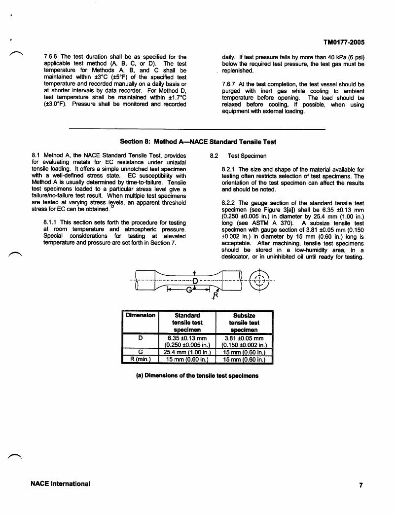
8.2.2 The gauge section of the standard tensile testspecimen (see Figure 3[a]) shall be 6.35 t0.13 mm(0.250 t0.005 in.) in diameter by 25.4 mm (1.00 in.)long (see ASTM A 370). A subsize tensile testspecimen with gauge section of 3.81 t0.05 mm (0.150t0.002 in.) in diameter by 15 mm (0.60 in.) long isacceptable. After machining, tensile test specimensshould be stored in a low-humidity area, in adesiccator, or in uninhibited oil until ready for testing.
(a) Dimenslons of the tensile test specimens
Dlmenslon Standardtensile testspecimen
Subslzetenslle testspeclmen
D 6.35 t0.13 mm(0.250 t0.005 in.)
3.81 t0.05 mm(0.150 t0.002 in.)
G 25.4 mm (1.00 in.) 15 mm (0.60 in.)R (min.) 15 mm (0.60 in.) 15 mm (0.60 in.)
NACE International

TM0177-2005
8.2.3 The radius of curvature at the ends of the gaugesedion shall be at least 15 mm (0.60 in.) to minimhestress concentrations and fillet failures.
8.2.3.1 Additional methods that have been foundhelpful in reducing fillet failures are to:
(1) eliminate undercutting of fillet rradii inmachined test specimens; and
(2) machine the test specimen gauge sec.tionwith a sllght (0.05- to 0.1&mm [0.002- to 0.00$in.l) taper that produces a minimum cross-sectionin the middle of the gauge section.
8.2.4 The ends of the test specimen must be longenough to accommodate seals for the test vessel andto make connections to the stressing fixture. (SeeFigure 3lbl.)
8.2.5 The test specimen must be machined or groundcarefully to avoid overheating and cold working in thegauge sec'tion. In machining operations, the final twopasses should remove no more than a total of 0.05 mm(0.002 in.) of material. Grinding is also acceptrable ifthe grinding process does not harden the material.
FIS Gas out to["t HS Gas tni lt IIY
UFORCE
(b) Tensile test specimen in an environmental chamber
FIGURE 3: Tensile Test Specimens
8.2.6 For all materials the final surface finish shall be0.81 pm (32 pin.) or finer. Final surface finish may beobtrained by mechanical polishing or electropolishing ifthe roughness requirement is met. Using any ftnishingprocess other than grinding must be reported with thetest data. When electropolishing, bath conditions mustbe such that the test specimen does not absorbhydrogen during the procedure.
8.2.7 When the stiandard tensile test specimen cannotbe obtiained ftom the material because of its size orshape, an appropriate subsize tensile test specimenmay be used. However, subsize tensile test specimenscan prcduce shorter failure times than those observedfor stiandard tensile test specimens. The report of testdatra using subsize tensile test specimens shall clearlystate the use and size of subsize test specimens.
8.2.8 Test Specimen ldentification
8.2.8.1 Stamping or vibratory stenciling may beused on the ends of the test specimen but shallnot be used in the gauge section.
NACE International

8.2.9 Test Specimen Cleaning
8.2.9.1 Before testing, test specimens shall bedegreased with solvent and rinsed with acetone.
8.2.9.2 The gauge section of the test specimenshall not be handled or contaminated aftercleaning.
8.3 Test Solutions (for Method A)+ee Section 6.
8.4 Test Equipment
8.4.1 Many types of stress fixtures and test vesselsused for stress onosion testing are aoceptable forMethod A. Consequently, the following discussionemphasizes the test equipment characteristics requiredfor selecting suitable items and procedures.
8.4.2 Tensile tests should be performed with constrant-load devices or sustiained-load {proof ring or spring-loaded) devices (see ASTM G 49'').
8.4.2.1 All loading devices shall be calibrated toensure accurate application of load to the testspecimen. The eror for loads within the
TM0177-2005
calibration range of the loading device shall notexceed 1.0o/o of the calibration load.
8.4.2.2 The loading device shall be constructed toavoid torsional ioads.
8.4.3 When susceptible materials are tested usingsustained-load devices, it is possible for cracks toinitiate and propagate only partially, not fully, throughthe test specimen (see Paragraph 8.7). Consequently,susceptibility determination fiom sustiained{oad testresults requires the visual examination of the testspecimens br the presence of part-through cracks.The determination may be difficult if the cncks aresmall and sparse or if obscured by conosion deposits.However, testing with constrant-load devices ensuresthat susceptible materials will separate completely.This result clearly identifies the material as susceptibleand does not rely on finding part-through cracks.
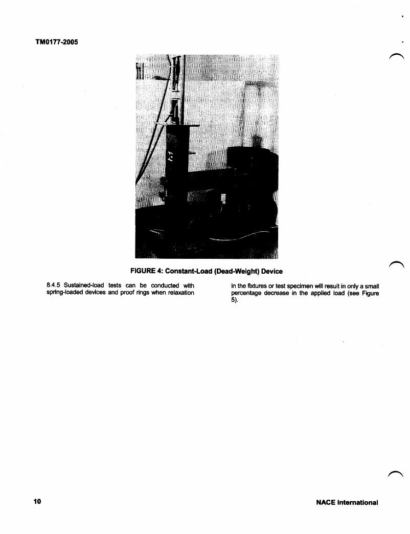
8.4.4 Dead-weight testers capable of maintaining'constant pressure on a hydraulic cell may be used forconstiant-load testing (see Figure 4).
NACE International
TM0177.2005
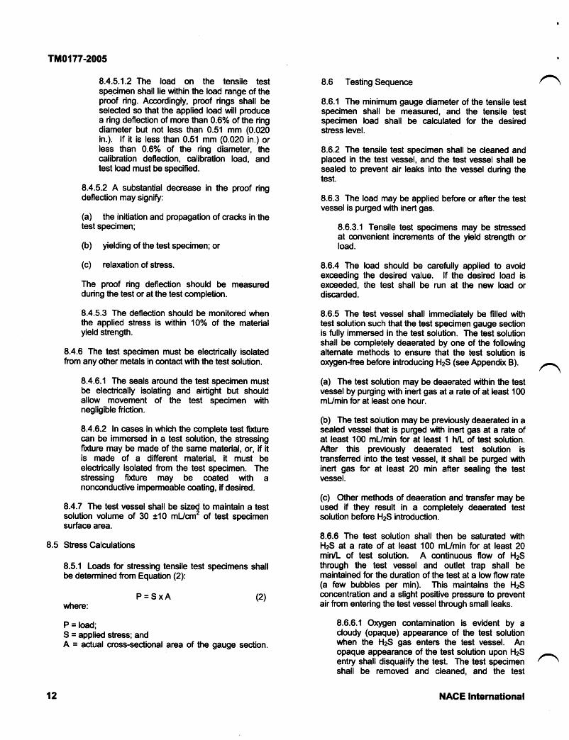
8.4.5 Sustained-load tests can be conducted withspring-loaded devices and proof rings wtren relaxation
FIGURE 4: Gonstant-Load (Dead-Weight) Device
in the fixtures or test specimen will result in only a smallpercentage decrease in the applied load (see Figure5).
10 NACE lnternational

8.4.5.1 In using proofprooedures are required:
(a) Proof ring
FIGURE 5: Sustained-Load Devices
TM0177-2005
8.4.5.1.1 Before calibration, proof rings shallbe preconditioned by stressing at least 10times to 1'lO% of the maximum load nting ofthe proof ring.
(b) Sprlng-loaded
NACE Intemational
rings, the following
11
TM0177-2005
8.4.5.1.2 The load on the tensile testspecimen shall lie within the load range of theproof ring. Accordingly, proof rings shall beselected so that the applied load will producea ring deflection of more than 0.6% of the ringdiameter but not less than 0.51 mm (0.020in.). lf it is less than 0.51 mm (0.020 in.) orless than 0.60/o of the ring diameter, thecalibration deflection, calibration load, andtest load must be specifted.
8.4.5.2 A substantial decrease in the proof ringdeflection may signifu:
(a) the initiation and propagation of cracks in thetest specimen;
(b) yielding of the test specimen; or
(c) relaxation of stress.
The proof ring deflection should be measuredduring the test or at the test completion.
8.4.5.3 The deflection should be monitored wfrenthe applied stress is within 1oo/o ol the materialyield strength.
8.4.6 The test specimen must be electrically isolatedfrom any other metials in contact with the test solution.
8.4.6.1 The seals around the test specimen mustbe electrically isolating and airtight but shouldallow movement of the test specimen withnegligible friction.
8.4.6.2 In cases in which the complete test fixturecan be immersed in a test solution, the stressingfixture may be made of the same material, or, if itis made of a different material, it must beelectrically isolated ftom the test specimen. Thestressing fixture may be coated with anonconduc'tive impermeable coating, if desired.
8.4.7 The test vessel shall be sized to maintain a testsolution volume of 30 t10 mUcm2 of test specimensurface area.
8.5 Stress Calculations
8.5.1 Loads for stressing tensile test specimens shallbe determined from Equation (2):
P=SxAwhere:
P = load;S = applied stress; andA = actual cross-sectional area of the gauge section.
8.6 Testing Sequence
8.6.1 The minimum gauge diameter of the tensile testspecimen shall be measured, and the tensile testspecimen load shall be calculated for the desiredstress level.
8.6.2 The tensile test specimen shall be cleaned andplaced in the test vessel, and the test vessel shall besealed to prevent air leaks into the vessel during thetest.
8.6.3 The load may be applied before or after the testvessel is purged with inert gas.
8.6.3.1 Tensile test specimens may be stressedat convenient increments of the yield strength orload.
8.6.4 The load should be carefully applied to avoidexceeding the desired value. lf the desired load isexceeded, the test shall be run at the new load ordiscarded.
8.6.5 The test vessel shall immediately be filled withtest solution such that the test specimen gauge sectionis fully immersed in the test solution. The test solutionshall be completely deaerated by one of the followingaltemate methods to ensure that the test solution isoxygen-free before introducing HzS (see Appendix B).
(a) The test solution may be deaerated within the testvessel by purging with inert gas at a rate of at least 100mUmin for at least one hour.
(b) The test solution may be previously deaerated in asealed vessel that is purged with inert gas at a rate ofat least 100 mUmin for at least t h/L of test solution.After this previously deaerated test solution istransfened into the test vessel, it shall be purged withinert gas for at least 20 min after sealing the testvessel.
(c) Other methods of deaeration and transfer may beused if they result in a completely deaerated testsolution before HzS introduction.
8.6.6 The test solution shall then be saturated withHzS at a rate of at least 100 mUmin for at least 20mir/L of test solution. A continuous flow of HzSthrough the test vessel and outlet trap shall bemaintained for the duration of the test at a low flow rate(a few bubbles per min). This maintains the HzSconcentration and a slight positive pressure to preventair from entering the test vessel through small leaks.
8.6.6.1 Orygen contiamination is evident by acloudy (opaque) appearance of the test solutionwhen the HzS gas enters the test vessel. Anopaque appearanoe of the test solution upon HzSentry shall disqualiff the test. The test specirnenshall be removed and cleaned, and the test
(2)
12 NACE International

solution makeup, transfer, and deaerationprocedure repeated.
8.6.7 The termination of the test shall be at tensile testspecimen failure or after 720 hours, whichever occursfirst.
8.6.8 When needed, additional tensile test specimensshall be tested to define dosely the no-failure stress.
8.7 Failure Detection
Following exposure, the surfaces of the gauge section ofthe nonfailed tensile test specimens shall be cleaned andinspec{ed for evidence of cracking. Those tensile testspecimens containing cracks shall be noted.
8.7.1 For all materials, failure is either:
(a) Complete separation of the tensile testspecimen; or
TM0177-2005
(b) Visual observation of cracks on the gaugesection of the tensile test specimen at 10X aftercompleting the T2Ghour test duration. Investigativetechniques employing metallography, scanningmicroscopy, el' mechanical testing may be used todetermine whether cracks on the gauge section areevidence of EC. lf it is verifted that the cracks are notEC, then the tensile test specimen passes the test.
8.7.2 Time-to-failure may be recorded using electricaltimers and microswitches.
8.8 Reporting of Test Results
8.8.1 Time-to-failure and no-failure data or the visualobseruation of surface cracks at the end of the testshall be reported for each stress level.
8.8.2 The chemical composition, heat treatment,mechanical properties, other information specifiedabove, and data taken shall be reported.
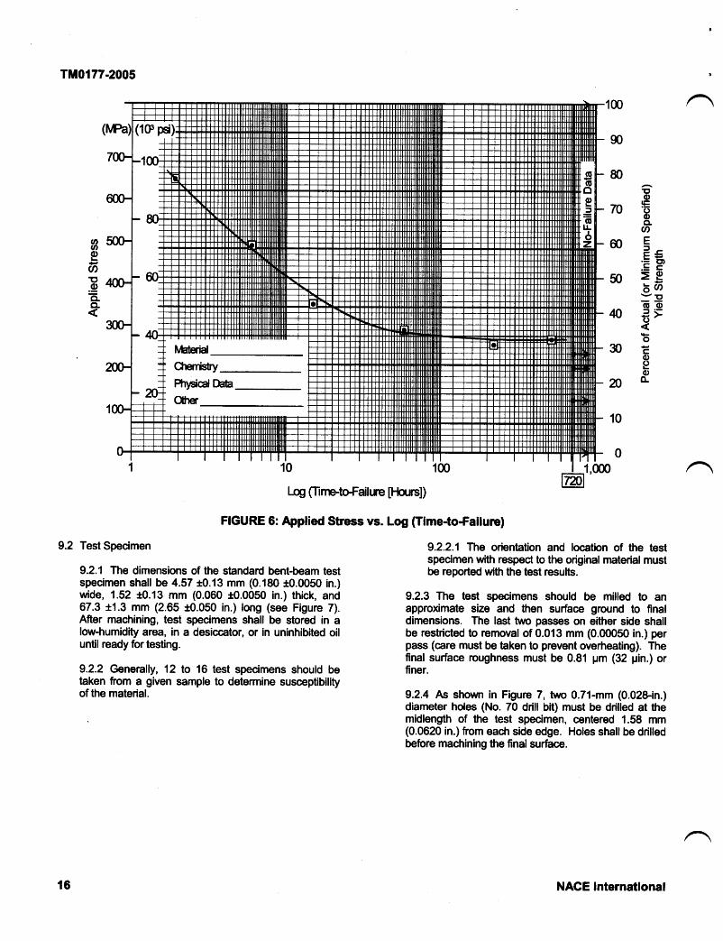
8.8.3 Table 1 shows the recommended format forreporting the data. Data may also be presented onsemilog graph paper (see Figure 6).
Section 9: Method B-l.lACE Standard Bent-Beam Test
9.1 Method B, the NACE Standard Bent-Beam Test,provides for testing carbon and low-alloy steels subjected totensile stress to evaluate resistance to cracking failure inlow-pH aqueous environments contiaining HzS. lt evaluatesEC susceptibility of these materials in the presence of astress concentration. The compact size of the bent-beamtest specimen facilitiates testing small, localized areas andthin materials. Bent-beam test specimens loaded to aparticular deflection give a failure/no-failure test result.When testing multiple test specimens at varying deflections,a statistically based critical stress factor (S") for a 50o/oprobability of failure can be obtained. NaCl is not added tothe test solution for this test method. Laboratory test datafor carbon and low-alloy steels have been found to conelatewtth field datia.ra
9.1.1 This section sets forth the procedure for bent-beam testing at room temperature and atmosphericpressure. Special considerations for testing at elevatedtemperature and pressure are set forth in Section 7.
9.1.2 Method B can be summarized as follovra:
9.1.2.1 This method involves deflecting each testspecimen in a series by applying a differentbending stress. The stressed test specimens then
are exposed to the test envircnment, and thefailure (or no-failure) by oacking is determined.From these datra obtained by testing multiple testspecimens at varying deflections, a statisticallybased Sc for a 50o/o probability of failure iscalculated to indicate the material's resistiance tossc.
9.1.2.2 This method constitutes a constant-deflection test of hph test specimen compliance.The computed stress is called a pseudo-stressbecause it does not reflect:
(a) ac'tual stress or stress distribution in the testspecinren;
(b) deviation from elasticity associated withplastic deformation; or
(c) decrease in stress in the test specimen as acrack or cracks grow.
Consequently, this method is not suitiable fordetermination of threshold stress.
NACE International 13

TM0177-2005
TABLE I-NACE Uniform illaterial Testing Report Form (Part 1):Testing in Accordanoe with NACE Standard TM0177(a
Method A,-],|ACE Standard Tensile Test
Submitting Company Submittial DateSubmitted by Telephone No. Testing LabAlloy Designation General MaterialType.
ll'Test method must be fully described if not in accordance with TM0177.jl) tttett prac'tice: open-heartir (OH), basic orygen fumace (BOF), electric fumace (EF), argon-orygen decarburization (AOD).(") E.g.,'*lO uprk, plating, nitriOin(j, prestrain.
t
!
Ghemistry
Heat N umber/ldentificatlon
cMnsiPsNiCrMoVAITiNbNCuOther
MaterialProcessing HistoryMelt Practice (e.9., OH,BOF, EF, AOD)(",
Product Form
Heat Treatment (Specifytime, temperature, andcooling mode for eachcyde in process.)
Other Mechanical,Thermal, Chemical, orCoating TreatmentG)
14 NAGE lnternational

)) )
TM0177-2005
TABLE I-NACE Uniform Material Testing Report Form (Part 2):Testing in Accordanoe with NACE Standard TM0177
Method A,-trlACE Standard Tensile TestLab Data for tlaterlal:
Test Specimen Geometry: I Standard I Nonstandard Nomlnal Dlameter Gauge Length
Tested per NAGE Standard TM0177(A)
Constant Load- E oeaO Welght fl Hydrautic Tloflt"iSustained Load-[ Proof Ring E Sprtng I OtneriD Post-Test Proof Ring Def,ection teasurement
Ghemlstry: E Test Solutlon A I Test Solutlon B E Test Solution G (deftne]
D Outtet Trap to Exclude Oxygen I temperature Maintalned 24o t3oG (75'tsoF)
D Ottrer Test Solution_
I temperature Maintained t3oc (ts'F)
Materialldentlllcation
Test Speclmen Propertles Test Stress (% of Yleld Strength) Applled HeatTreatment
Remarks(lncludlngSurface
Gonditlonand HzSLevel)
^g6tS-g *'*
Time-to-Failure (Hours)NF = No Failure at720 hours
NACE International 15
TM0177-2005
9.2
ao70Eo
CLU'
ME-ss:=P
50 >g6cn
=ooon .E;<o30Eoeono-
ooEatt.oo-CL
I
^
10
Test Specimen
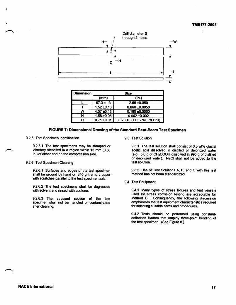
9.2.1 The dimensions of the stiandard bent-beam testspecimen shall be 4.57 t0.13 mm (0.180 *0.0050 in.)wide, 1.52 10.13 mm (0.060 10.0050 in.) thick, and67.3 t1.3 mm (2.65 t0.050 in.) long (see Figure 7).After machining, test specimens shall be stored in alow-humidity area, in a desiccator, or in uninhibited oiluntil ready for testing.
9.2.2 @nerally, 12 to 16 test specimens should betraken from a given sample to determine susceptibilityof the material.
FIGURE 6: Applied Stress vs. Log (Time-to-Failure)
1,000
9.2.2.1 The orientration and location of the testspecimen with respect to the original material mustbe reported with the test results.
9.2.3 The test specimens should be milled to anapproximate size and then surface ground to finaldimensbns. The last two passes on either side shallbe restricted to removal of 0.013 mm (0.@050 in.) perpass (care must be taken to prevent overheating). Thefinal surface roughness must be 0.81 pm (32 pin.) orfiner.
9.2.4 As shown in Figure 7, two 0.71-mm (0.02&in.)diameter holes (No. 70 drill bit) must be drilled at themidlength of the test specimen, centered 1.58 mm(0.0620 in.) ffom each side edge. Holes shall be drilledbeflcre machining the final surface.
FlT icd kOher
Log CnnetoFdue [Fh^rs])
16 NACE International
!
t
9.2.5 Test Specimen ldentification
9.2.5.1 The test specimens may be stiamped orvibratory stenciled in a region within 13 mm (0.50in.) of either end on the compression side.
9.2.6 Test Specimen Cleaning
9.2.6.1 Surfaces and edges of the test specimenshall be ground by hand on 24O grit emery paperwith scratches parallelto the test spednren axis.
9.2.6.2 The test specimens shall be degreasedwith solvent and rinsed with acetone.
9.2.6.3 The stressed section of the testspecimen shall not be handled or contiaminatedafier cleaning.
Tit0177-2005
9.3 Test Solution
9.3.1 The test solution shall consist of 0.5 wt% glacialacetic acid dissolved in distilled or deionized water(e.9., 5.0 g of CH3COOH dissolved in 995 g of distilledor deionized ulater). NaCl shall not be added to thetest solution.
9.3.2 Use of Test Solutions A, B, and C with this testmethod has not been strandardized.
9.4 Test Equipment
9.4.1 Many types of stress fixtures and test vesselsused for stress conosion testing are acceptiable forMethod B. Consequently, the following discussionemphasizes the test equipment characteristics requiredfor selecting suitable items and procedures.
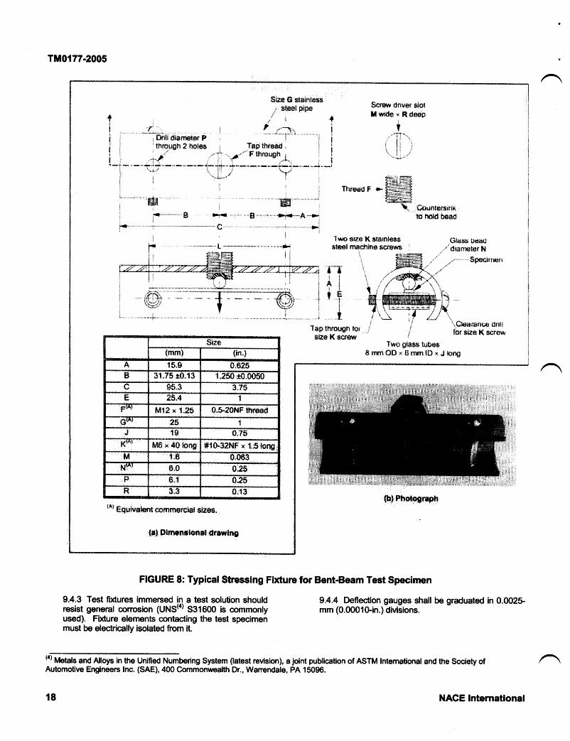
9.4.2 Tests should be perfonned using constiant-deflection fixtures that employ three-point bending ofthe test specimen. (See Figure 8.)
fwt
|-tt
Dimension Size(mm) (in.)
L 67.3 t1.3 2.65 10.050t 1.52 r0.13 0.060 10.0050
W 4.57 r0.13 0.180 10.0050H 1.58 10.05 0.062 10.002D 0.71 t0.01 0.028 t0.0005 (No. 70 Drill)
FIGURE 7: Dimensional Drawing of the Standard Bent-Beam Test Specimen
Drill diameter Dthrough 2 holes
NACE International 17
TMo{77-2005
$ize
tmml (in.)
A 1$_g 0.6255 31.75 r0.13 1.?50 *S.0050c gs"3 3"75E 25.4 1
pl*l *rt12 x 1.25 S"$,I0NF thrEad
G{*} as 1
J rs 0.?s;4t*l MS x 40 bng #1&32NF x 1.5longM 1,6 0.063
gtrt 6.0 03$F s.t 0 5R $-3 0,13
{^} Equl$al6nt,rssf!!$}Erslil sEes.
9.4.3 Test fixtures immersed in a test solution shouldresist general corrosion (UruStrl $1600 is commonlyused). Fixture elements contacting the test specimenmust be electrically isolated ftom it.
Sire G stainless," steelpipe
!' "il +i r' , i o.--]:. i
i i '"*ffilidiarnetpr# , -.-i'' i i; i thretgh2holes ; TaPlhread, i i: i , ,! ."Fthrar.qh i ii I .Tt' ,"|;-ra''!*i * ***{r;;n---*-*".--,*::ii*T--**--- a{il1-*-..;..*l
i ; t,"-i*-i Y" :
ii :
:i.ji
i"*uFT'.@---.'&K'l
B -rr'<*A--->i
'.. --*' -.....- . -. -..-. ..1'"" . ...' -."..''.*.
l'
$erwr dnv6r *lstil wrde * R,deep
j
I
."-Ti1." i| ",,
i it ii,. tl :.
#ffifirreadr -ffiffic""ff#fffi:
Iwo sae K stamlesssteelmach;ne screrirs
GiE$s $*e{"/disryEter ll
..,.,.r"''"'' $P€c*nmn
r*r i
+li+lifFil
...-i ... _t
Tap througfr forslze X $c{€r.$
\
t\
at
ffi1\f
J
{*}. Slrnsnrloilrt {trrwlnf,
FIGURE 8: Typical Stressing Fixture for Bent-Beam Test Specimen
Two gfa*s USeaImm0Dr.SrnmlSeJt$r€
9.4.4 Deflection gauges shall be graduated in 0.@2$mm (0.0001 Gin.) divisions.
(a) Metals and Allop in the Unified Numbering Sptem (atest revision), a joint publication of ASTM Intemational and the Society of
Automotive Engineers lnc. (SAE),400 Commonwealth Dr., Wanendale, PA 15096.
18 NACE International

9.4.4.1 Test specimen deflection should bedetermined by separate gauges or by gaugesincorporated in a loading fixture. In designing adeflection gauge to suit individual circumstiances,the deflection at midlength of the test specimenshould be measured.
9.4.5 Test Vessel
9.4.5.1 The test vessel shall be sized to maintaina test solution volume of 30 t10 mUcm2 of testspecimen surface area. Maximum volume of thetest vessel should be 10 L.
9.4.5.2 The test vessel shall be valved at bothinlet and outlet to prevent contiamination of the testsolution by orygen.
9.4.5.3 A fritted glass bubbler shall be used tointroduce the inert gas and HzS below the anay oftest specimens. The bubbles should not impingeon the test specimens.
Defl ection Calculations
9.5.1 An estimated outer fiber pseudo-stress (S) forthe material shall be used in beam deflectioncalculations. For carbon and low-alloy stgels, S valuesare typically in the range of 69 MPa (104 psi) at 22 to24 HRC. As hardness increases, S generallydecreases.
9.5.2 The selected range of estimated S values shallbe used as pseudo-stresses to calculate thedeflections of the test specimens.
9.5.3 The test specimen deflection shall be calculatedfor each of the pseudo-stress values using Equation(3):
sfp=-6Et
where:
D = deflection;S = nominal outer fiber pseudo-stress;
/ = distance between end supports;E = elastic modulus; andt = thickness of test specimen.
The formula assumes elastic conditions and ignoresthe stress concentration effect of the holes and the testspecimen plasticity at high stress levels.
TM0177-2005
Testing Sequence
9.6.1 The test specimen dimensions shall bemeasured, and deflections shall be calculated fordesired pseudo-stress levels.
9.6.2 Test specimens shall be stressed in fixtures bydeflecting them to the nearest 0.0025 mm (0.00010 in.)with dialgauge and fildure.
9.6.2.1 The deflection should be caretully appliedto avoid exceeding the desired value. lf thedesired deflection is exceeded. the test shall berun at the higher deflection or discarded.
9.6.3 The stressed test specimens shall be cleanedand placed into the test vessel.
9.6.4 The test vessel shall be filled immediately withdearated test solution and sealed. The test solutionshall be completely deaerated by one of the followingaltemate methods to ensure that the test solution isorygen-ftee before introducing HzS (see Appendix B).
(a) The test solution may be deaerated within the testvessel by purging with inert gas at a rate of at least 1@mUmin for at least one hour.
(b) The test solution may be previously deaerated in asealed vessel that is purged with inert gas at a rate ofat least 100 mUmin for at least 1 t/L of test solution.After this previously deaerated test solution istransfened into the test vessel, it shall be purged withinert gas for at least 20 min after sealing the testvessel.
(c) CIher methods of deaeration and transfer may beused if they result in a completely deaerated testsolution prior to HzS introduction.
9.6.5 The test solution shall then be saturated withHzS at a rate of at least 100 mUmin for at least 20min/L of test solution. The HzS in the test vessel shallbe replenished periodically by bubbling HzS for aduration of 20 to 30 min at a rate of at least 100 mUminper liter of test solution three times per week for theduration of the test. The days for the replenishmentshould be the first, third, and fifth day of each week.
9.6.5.1 Orygen contiamination is evident by acloudy (opaque) appearanoe in the test solutionwhen the HzS gas enters the test vessel. Anopaque appearanoe to the test solution upon HzSentry shall disqualiff the test. The test specimenshall be removed and cleaned, and the testsolution makeup, transfer, and deaerationprocedures repeated.
9.6.6 The test shall be terminated after 720 hours orwhen all test specimens have failed, wfrichever o@ursfirst.
9.6
9.5
(3)
NACE lnternational 19
TM0177-2005
9.6.7 Additional test specimens and iterative testingmay be necessary to define the Sc closely.
9.8 Failure Detection
9.8.1 Crack presence shall be determined visually withthe aid of a low-power binocular microscope. lf the testspecimen contiains only one or a few cracks, the shapeof the test specimen may have changed considerably,predominantly by kinking; this feature helps to identifycracked test specimens. However, if many cracks arepresent, a shape change may not be apparent.Because corrosion prcducts may obscure cracks, acareful examination shall be made. Mechanicalcleaning or metiallographic sectioning of the testspecimen may be necessary in these instances todetect cracks.
9.8.2 Failurc is cracking of the test specimen.Consequently, following exposure, the surface of thetest specimens should be cleaned and visuallyinspected at 10X for evidence of cracking following a20degree bending by hand. Test specimens found tocontain cracks shall be considered failed.
9.9 Reporting of Test Results
9.9.1 Failure/no-failure datia and nominal outer fiberpseudo-stress (S) values shall be reported. Time-to-failure datia are optional.
9.9.2 The Sc shall be calculated using Equation (4) forS values expressed in MPa, or Equation (5) for Svalues expressed in psi:
where:
S = nominal outer fiber pseudo-stress (in MPa) used tocalculate the beam's deflec'tion;T = the test resuft (i.e., +1 for passing and -1 forfailure); andn = the total number of test specimens tested.
When using Equation (4), all pseudo-stress datia thatare more than t210 MPa from the initial calculatedvalue S" x 68.95 MPa shall be discarded, and a new S"value shall be recalculated. The recalculated S" valueeliminates low and high bias data.
>S + zlts" : toapsi
(s)
where:
S = nominal outer fiber pseudo-stress (in psi) used tocalculate the beam's deflection;T = the test result (i.e., +1 for passing and -1 forfailure); andn = the totral number of test specimens tested.
When using Equation (5), all pseudo-stress data thatare more than.t3.0 x 10" psi ftom the initial calculatedvalue S" x 104 psi shall 6e OiscarOed, and a new S" nvalue shall be recalculated. The recalculated S" value ' \
eliminates low and high bias data.
9.9.3 The calculated S" value for each material testedshall be reported. lf S" is recalculated, the recalculatedS" value shall be reported, not the initial calculated Scvalue.
9.9.4 The chemical compositions, heat treafrnent,mechanical properties, and other data traken shall bereported.
9.9.5 Table 2 shows the re@mmended format forreporting the data.
*fi*+2Er (4)sc
Section 10: Method H{ACE Standard G-Ring Test
10.1 Method C, the NACE Standard GRing Test,provides for evaluating the EC resistance of metals underconditions of circumferential loading (hoop stress). lt isparticularly suitiable for making transverse tests of tubingand bar. EC susceptibility with the C+ing test specimen isusually determined by tirne-tocracking during the test. C-ring test specimens, when deflected to a particular outerfiber stress level, give a failure/no-fiailure result. Whentesting multiple Gring test specimens at varying stresslevels, an apparent threshold stress for EC can be obtained.
10.1.1 This section sets forth the procedure for C-ringtesting at room temperature and atmospheric pressure.Special considerations for testing at elevated
tempemture and pressure are set forth in Section 7.
10.2 Test Specimen
10.2.1 An unnotched C-flng test specimen inaccordance with ASTM G 38'" shall be used. Sizes forC-rings may be varied over a wide range, but C-ringswith an outside diameter (OD) of less than about 15.9mm (0.625 in.) should not be used because of
20 NACE International

increased difficulties in machining and decreasedprecision in stressing. A typical Gring test specimen isshown in Figure 9.
10.2.2 The circumferential stress may vary across thewidth of the C-ring; the variation extent depends on thewidth-tothickness (wlt) and diameter-to-thickness (d/t)ratios of the C-ring. The wft ratio shall be betueen 2and 10, and the d/t ratio shall be between 10 and 100.
10.2.3 The material used in the bolting fixtures shallbe of the same material as that of the Gring testspecimen or be electrically isolated from the G-ring testspecirnen to minimize any galvanic effects, unlessspeciftc galvanic effects are desired.
TM0177-2005
10.2.4 Machining should be done in stages: thefinal tvro passes should remove a total of no morethan 0.05 mm (0.002 in.) of metal, and the final cutshould leave the principal surface with a finish of0.81 pm (32 pin.) or finer. After machining, testspecimens shall be stored in a low-humidity area, ina desiccator, or in uninhibited oil until ready fortesting.
10.2.4.1 A high-quality machined surface isnormally used for conosion test purposes.However, the as-fabricated surface of a tube orbar also may be evaluated by C-ring testspecimens. Using any finishing process otherthan machining must be reported with the testdatra.
21NACE International

TM0177-2005
TABLE 2-I{ACE Uniform Material Testing Report Form (Part 1):Testing in Accordance with NACE Standard TM0177(4
Method B-NACE Standard Bent-Beam Test
Submitting Company Submittal DateSubmitted by Telephone No. Testing LabAlloy Designation General MaterialType.
f'Test method must be fully descdbed if not in accordance with TM0177.jfltvtett practice: open-hearth (OH), basic orygen fumace (BOF), electric fumace (EF), argon-orygen decarburization (AOD).(") E.g., cold urork, plating, nfuiding, prestrain.
a
I
Chemistry
Heat N um ber/ldentiflcation
cMnsiPSNiCrMoVAITiNbNCuOther
MaterialPrccessingHistoryMelt Practice(e.9., QH, BOF, EF,AOD)(o,
Product Form
Heat Treatment (Specrfftime, temperature, andcooling mode for eachcycle in process.)
Other Mechanical,Thermal, Chemical.orCoating Treatment
22 NACE Intemational

)) )'
TM0177-2005
TABLE 2-NACE Uniform tlaterial Testing Report Form (Part 2):Testing in Accordance with NACE Standard TM0177
Method B-i{ACE Standard Bent-Beam TestLab Data for taterlal: Tested per NACE Standard TM0177(A)
LengthTest Specimen Geometry: I Standard D Nonstandard Nominal Sizef] Statlstical Sc Method Applled
Ghemistry: [ 0.5 rrf/o glaclal acetlc acid In dletllled or delonized water D Ottrer Test Solution
E Outtet Trap to Exclude Oxygen I temperature Malntalnedz4" t3oG (75'ts'F) E temperature tlaintained t3"c (ts'F)
:TE3t rn€thod must b€ fuly d€scrlb€d ll not In accodenc€ with I'IACE Sbndard TM0l77.(",Locafmofbst8p€c|m€nmayb€:tubu|aB-.{ut8usdiam6t€r(oD),m|ds6||(Mvv),orinsid€diam9t€r(|D);so|ids.--euthce(S)'qual
tE).:pri€ntatim may bE longlhldirEl (L) or hans€r8e (T).
:pp€n paEnthos$ must b6 frll€d wth m6tdc or Engllsh unlts, a8 appEpdat8 to lh6 data. Yl€ld stFnglh ls ssum€d to b6 0.2% ofis€t unl€a8 olfislwE€ notsd.t'Ent€. pH lor test conductad on nontellsd b€nt-bsfln bst s@mon at hlgh€st sbess F summadZng dab.
I{ACE lntemational
Materialldentlflcatlon
Psuedo€tress (S) Value ( AppliedHeat
Treatment
Remarks(lncludingSurface
Gonditlonand HzSLevel)
nU,-J
-d d'dd=o
^C"C---0 3Eg=o{o
fgo
G>ngd qoE'o-6'f:f
Time-to-Failure (Hours)NF = No Failure at720 hours
23

Tlrl0177-2005
14.2.5 Test Specimen ldentiftcation
10.2.5.1 The C-ring test specimen end segmentsmay be stamped or vibratory stenciled.
10.2.6 Test Specimen Cleaning
10.2.6.1 Before testing, C-ring test specimensshall be degreased with solvent and rinsed withacetone.
10.2.6.2 After cleaning, the test section of the C-ring test specimen shall not be handled orcontaminated.
10.3 Test Solutions for Method C,-see Sec'tion 6.
10.4 Test Equipment
10.4.1 The test equipment necessary for stressing C-ring test specimens shall indude calipers or equivalentequipment capable of measuring to the nearest 0.025mm (0.0010 in.), wrenches sized to the bolting fixturesused, and a clamping device.
10.4.1.1 Gring test specimens shall be clampedduring stressing by the bolting fixtures or the tips ofthe Gring. No clamping shall trake place in thecentraltest section of the Gring.
24
w12
ERILL 2.HOLESaT 1,S0'
10.4.2 The C-ring test specimen shall be so supportedthat nothing except the test solution contacts thestressed area.
10.4.2.1 The supporting fixture shall beconstructed of material compatible with the testsolution.
10.4.2.2 Galvanic effects between the C+ing testspecimens, supporting fixtures, and test vesselshall be avoided. For example, an isolatingbushing or washer can be used to isolate the C-ring elec'trically from the supporting fixtures.
10.4.3 TestVessel
10.4.3.1 The test vessel should be sized tomaintain a test solution volume of 30 t10 mUcm2of test specimen surface area.
10.4.3.2 A fritted glass bubbler shall be used tointroduce the inert gas and HzS below the anay ofGring test specimens. The bubbles should notimpinge on the C-ring test specimens.
10.5 DeflectionCalculations
t
FIGURE 9: Dimensional Drawing of the Gfling Test Specimen
NACE International

10.5.1 The deflection necessary to obtrain the desiredstress on the Gring test specimen shall be calculatedusing Equation (6):
nd(d-t)Sp=-4tE
where:
D = deflection of Gring test specimen across boltholes;d = C-ring test specimen outer diameter;t = Gring test specimen thickness;S = desired outer fiber stress; andE = modulus of elasticity.
10.5.1.1 Deflections calculated by Equation (6)should be limited to stresses below the materialelastic limit. For many CRAs the elastic limit iswell below the O.2o/o offset proof (yield) stress.Deflection values beyond the elastic limit can becalculated from information obtained from thestress-strain curve of the material and the strain-deflection characteristics of the specific C-ringgeometry being used.
10.5.1.2 Equation (6) can be used to calculatethe deflection necessary to stress the testspecimen to 100o/o of the 0.2o/o ofbet yieldstrength (Sv) by substituting Sv + E (0.002) for S inthe original equation. This relationship is not validfor allalloy sptems and should be checked beforeuse on materials other than carbon and low-alloysteels.
10.5.1.3 No equation exists to calculate thedeflection needed to stress Gring test specimensto values between the material's elastic limit andits 0.2olo offset proof (yield) stress.
',0.5.2 The deflection can be determined directly byusing electrical resistance strain gauges applied to theGring test specimen.
10.5.2.1 Each Gring shall be straingauged onthe outside diameter at a point 90" opposite theaxis of the C-ring bolt. The bolt shall be tightenedto the appropriate strain by monitoring the straingauge output, then the strain gauge and glueresidue shall be removed. The C-ring shall thenbe recleaned using the same procedures given inParagraph 10.2.6.
10.6 Testing Sequence
10.6.1 The C-ring test specimen dimensions shall bemeasured, and the conesponding C-ring deflectionsshall be calculated.
',0.6.2 C-ring test specimens shall be stressed bytightening botting fixtures to calculated deflectionsmeasured to the nearest 0.025 mm (0.0010 in.).
NACE International
TM0177-2005
10.6.2.1 Deflections shall be measured at thecenter line of the bolting fixture. Thesemeasurements may be taken at the outerdiameter, inner diameter, or midwall with care tomaintain consistency in the points ofmeasurement. lf the desired deflection isexceeded, the test shall be run at the higherdeflection or discarded.
10.6.3 The Gring test specimens shall be cleanedand placed into the test vessel.
10.6.4 The test vessel shall be filled immediately withtest solution and sealed. The test solution shall becompletely deaerated by one of the following altematemethods to ensure that the test solution is orygen-freebefore introducing HzS (see Appendix B).
(a) The test solution may be deaerated within the testvessel by purging with inert gas at a rate of at least 1@mUmin for at least one hour.
(b) The test solution may be previously deaerated in asealed vessel that is puryed with inert gas at a rate ofat least 100 mUmin for at least t h/L of test solution.After this previously deaerated test solution istransfened into the test vessel, it shall be purged wtthinert gas for at least 20 min after sealing the testvessel.
(c) Other methods of deaeration and transfer may beused if they result in a completely deaerated testsolution prior to HzS introduction.
10.6.5 The test solution shall then be saturated withHzS at a rate of at least 100 mUmin for at least 20min/L of test solution. A continuous HzS flow throughthe test vessel and outlet trap shall be maintained forthe duration of the test at a lor flow rate (a few bubblesper min). This maintains the HzS concentration and aslight positive pressure to prevent air from entering thetest vessel through small leaks.
10.6.5.1 Orygen contiamination is evident by acloudy (opaque) appearance in the test solutionwhen the HzS gas enters the test vessel. Anopaque appearance to the test solution upon H2Sentry shall disqualifo the test. The test specimenshall be removed and cleaned, and the testsolution makeup, transfer, and deaerationprocedures repeated.
10.6.6 The test duration shall be 720 hours or until allC-ring test specimens have failed, wfrichever occursfirct.
10.7 Failure Detection
10.7.1 Highly stressed C-rings of alloys that areappreciably susceptible to EC tend to ftacture throughthe entire thickness or to crack in a nay that isconspicuous. However, with more-EGresistant alloys,
(6)
25
TMot77-2005
cracking frequently begins slowly and is difftcult todetect. Small crac*s may initiate at multiple sites andbe obscured by conosion products. lt is preferable toreport the first crack, if detected at 10X magnification,as the criterion of failure. An altemative method ofexposing oacking in C-rings after etgosure is to stressthe C-ring beyond the tested stress level. Cracksresulting from EC can be differentiated frommechanically induced cracks by the conoded nature ofthe crack surfiace.
10.8 Reporting of Results
10.8.1 Failure/no-failure data shall be reported fromeach stress level. lf time-to-failure data are recorded,they shall be reported.
10.8.2 The chemical composition, heat treatment,mechanical properties, and other data taken shall bereported.
10.8.3 Table 3 shows the recommended format forreporting the datra.
I
^.
Section 11: Method IH{ACE Standard DCB Test
11.1 Method D, the NACE Standard DCB Test, providesfor measuring the resistiance of metallic materials topropagation of EC, expressed in terms of a critical stressintensity factor, Krssc for SSC and Krec for the more generalcase of EC, using a crack-anest type of fracture mechanicstest. Method D does not depend on the uncertiainty ofpitting and/or crack initiation, because a crack is alwaysinitiated in a valid test. For SSC testing of carbon and low-alloy steels this method requires little time. Method D givesa direct numerical rating of crack propagation resistanceand dqgs not depend on evaluation of failure/no-failureresults.l6 The subject of facture mechanics testing forevaluation of EC resistance is cunently under considerationby NACE TG 085 and Work Group (WG) 08Sc, and ASTMCommittees E 8.06.02 and G 1.06.04. The user of thisstiandard should maintain contact with these groups andtheir technical activities for knowledge of cunent strate-of-the-art testing techniques.
11.1.1 This section sets forth the procedure for DCBtesting at rcom temperaturc and atmospheric pressure
and enables computation of Krssc. When the specialconsiderations set forth in Section 7 tor testing atelevated temperature and pressure are observed, thecomputed stress intensity factor should be written asKrec. The equations needed to compute Krec ar€ thesame as those set forth in Paragraph 11.6 for Kssc.However, the following descriptions of materialbehavior under SSC conditions may not be accurateforthe more general conditions of EC.
11.2 Test Specimen
11.2.1 The standard DCB test specimen design shallbe in accordance with Figure 10(a). A double-taperedwedge shall be used to load the DCB test specimen(see Figure 10tbl). The double-trapered wedge shall bemade of the same material as the DCB test specimenor of the same class of material as the DCB testspecimen. The wedge material may be heat treated orcold worked to increase its hardness and thereby helpto prevent galling during wedge insertion. Wedgesmay be shielded with polytetrafluoroethylene (PTFE)tape to reduce conosion in the wedge region.
^
26 NACE Intemational

TABLE LNACE Uniform Material Testing Report Form (Part l):Testing in Accordance with NACE Standard Tm0177(4
Submifting Company
ilethod C-NACE Standard C-Ring Test
Submittral DateSubmitted by Telephone No. Testing Lab,Alloy Designation General Material Type
Chemistry
Heat Number/ldentification
cMnSiPSNiCrMoVAITiNbNCuOther
MaterialProcessing Historytttlelt Practice (e.9., OH,BOF, EF, AOD)(",
Product Form
Heat Treatment (Specifytime, temperature, andcooling mode for eachcycle in proess.)
Other Mechanical,Thermal, Chemica[rorCoating Treatment
llf Test meffiod must be fully described if not in accordance with TM0177.
!)t"tett practice: open-hearth (OH), basic orygen fumace (BOF), electric fumace (EF), argon-orygen decarburization (AOD).(C) C ^
--lrf .^^rt
'^l-li^^ aildzliaa nmatminE.9., cold uork, plating, nibiding, prestrain.
TM0177-2005
NACE International 27

TM0177-2005
Lab Data for tlaterial:
TABLE 3-trlAGE uniform Material resting Report Form (part 2):Testing In Accordance with NACE Standard TMOlZz
Method C-I{ACE Standard G-RingTest
Tested per NAGE Standard Tltl0l77(Al
Test Speclmen Geomelry: Outside Dlameter _Test Equlpment: [J eonlng illaterial Same as Speclmen
f] Conection for Yleld Applled
Wall/Thlckness width
Ch.mllity: E Tcat Solutlon A El T.tt Solutlon B E Tc* Sotutlon C (dof,nel_ E Othor Tert Soluton
E Outlet Trap to Exclude Oxygen ff temperature Malntatned 24"C t3oG (75.F ts.F) D Temperature ilaintalned t3.C (tS.F)
NACE International
)d))
Materlalldentiffcatlon
Appfled Stress (o/o ol Yleld Strength) ApplledHeat
Treatment
Remarks(lncludlngSurface
Gondltionand HzSLevel)
t,l #t
Time-to-Failure (Hours)NF = No Failure at720 hours
28

11.2.2 The standard DCB test specimen thicknessshall be nomiiraily 9.53 mm (0.375 in.); completedimensions are shown in Figure 10(a). When thematerial being tested is too thin to meet thisrequirement, optional thicknesses as noted in the ftguremay be considered. Subsize DCB test specimens ofsome carbon and low-alloy steels may give lower Krsscvalues than the standard DCB test specimens;differences as high as 37o/o have been observed.Further work is necessary to quantiff this effect.
11.2.3 Full-thickness DCB test specimens may beprepared ftom tubular products if the ratio of the tubularoutside diameter to the wall thickness is greater than10. The side grooves should be 20o/o of the wallthickness, thus maintaining a web thickness (Bn) equalto 60% of the wallthickness.
11.2.4 The side grooves must be machined carefullyto avoid overheating and cold working. The ftnal twomachining passes should remove a totral of 0.05 mm(0.002 in.) of metal. Grinding is also acceptable if theprocess does not harden the material.
11.2.5 In testing materials of low Kscc (below 22to27MPa{m [20 to 25 ksi{in.l) or materials in which crackinitiation is difficult, e.9., lower-yield-strengilh materials,introducing the electrodischarge-machined (EDM) slotnoted in Figure 10(a) or a fat(;ue precrack is veryhelpful in avoiding side-cracking and in initiating SSC,respectively. Fatigue precracking of the DCBspecimen should be conducted under load control at aconvenient frequency. The acceptrable range for a
TM0177-2005
fatigue precrack is 1 to 3 mm (0.04 to 0.12 in.) past thebase of the chevron. To avoid eroneous high results,the maximum precracking load shall be the lesser of7oo/o of the expected initial Krimparted by the wedge or30 MPa{m (27 ksi{in.). The ratio of minimum tomaximum load shall be in the range of 0.1 to 0.2. Theprecrack should be sharpened at tvrto-thirds of themaximum precracking load for approximately 20,000cycles to extend the crack through any zone of residualcompressive stresses that might have developed.
1'4.2.6 Test Specimen ldentification
11.2.6.1 Each sidearm of the DCB test specimenshould be identified by stamping or vibratorystenciling, either near the two holes or on the endthat is not wedge loaded.
1'1.2.7 Dimensional Check
11.2.7.1 Dimensions B, Bn, 2h, and the distianceof the hole centers fnom the near end of the DCBtest specimen shall be measured. (A blademicrometer should be used for measuring Bn.)Any values that lie outside the limits shown inFigure 10(a) shall be recorded for later use incomputing l(ssc (see Paragraph 11.6.3).
11.2.8 Test Specimen Cleaning
11.2.8.'a Test specimens shall be degreased withsolvent and rinsed in acetone.
NACE Intemational 29

TM0177-2005
Jt
T
o
^
BlutmdodorC
Ng[Ei t is $fident b gtw the specffied armdlsplacement.
(b) Double-tapeied wcdgo
JE
ITI
B l'-
@-E
jt(mm) (ln.) (mm) (ln.)
4.76 0.188 2.86 0.113
6.35 0.250 3.81 0.150
12.7 0.500 7.62 0.300
Fullwall 0,6 B
NgESi
4 I O9e.tq".lrnel of length U may be used lf rrery lorr cracklng reslsbnce is expocted.- A ehort eloctodlscharge-machlneO GOU) 8lot, X thlck, enenOing b a ded0r of y ftom theslofred end, may be.subsllUbd br the dre,rron crack starbr. Addl6nally, th6 fi*quhr portonof the cfrevron q?y be ellminabd br the sake of macfilnlng effciency, dtlirU a sqriared end tothe slot {To amld dde-arm breakofr, it b reoomm€ndod that the r,eoi oouoni of ttie wedge ebt
A be roun@ or beveled.)\ Grmves must be oentehrO wlthln to,lerane Z andmust be opposite nnthh blerance Z.
Dlrnenelon Slze(mm) 0n.)
B .53 t0.05 .375 10.002B" .72 10.05 .?,25 fr.002D 4.85 0. 91 (No. 11 Drlll)E 6.4 +9.2r 4.6 0.25 +0.01/.0.00F t 10.10 .250 t0.004G r0.05 '5 10.002h 12.70 10.05 0.500 10.002J 36.10 r1.59 1.5m t(}.OdX)K .17 fr.77 0.125 10.031L I 1.60 11.59 4.000 10.0630M 5l r13 2.0 r0.5N 6.35 r0.10 0.250 10.004R 0.25 10.05 0.010 10.002s 2.38 t0.05 0.094 10.002U 130 5w 25.40 t().05 1.000 f).002X 0.3 0.01Y 41.3 1.6:lz r0.05 r0.002
(a) Derlgn
Secilon A-A
il bplcalUCr dOccA(d[hg ortbr]
30
FIGURE l0: DCB Specimen
NACE Intemational
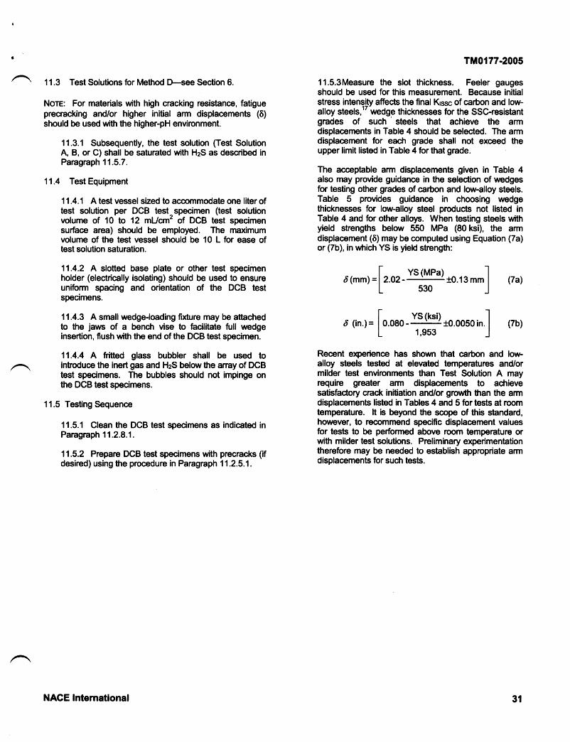
11.3 Test Solutions for Method f-see Section 6.
Nore: For materials with high cracking resistance, fatigueprecracking and/or higher initial arm displacements (6)should be used with the higher-pH environment.
11.3.1 Subsequently, the test solution (Test SolutionA, B, or C) shall be saturated with HzS as described inParagraph 11.5.7.
11.4 Test Equipment
11.4.'l A test vessel sized to accommodate one liter oftest solution per DCB test^specimen (test solutionvolume of 10 to 12 mUcm' of DGB test specimensurface area) should be employed. The maximumvolume of the test vessel should be 10 L for ease oftest solution saturation.
11.4.2 A slotted base plate or other test specimenholder (electrically isolating) should be used to ensureuniform spacing and orientation of the DCB testspecimens.
11.4.3 A small wedge-loading fixture may be attrachedto the jaws of a bench vise to facilitate full wedgeinsertion, flush with the end of the DCB test specimen.
11.4.4 A fritted glass bubbler shall be used tointroduce the inert gas and HzS below the anay of DCBtest specimens. The bubbles should not impinge onthe DCB test specimens.
11.5 Testing Sequence
11.5.1 Clean the DCB test specimens as indicated inParagraph 11.2.8.1.
11.5.2 Prepare DCB test specimens with precracks (ifdesired) using the procedure in Paragraph 11.2.5.1.
TM0177-2005
11.5.3Measure the slot thickness. Feeler gaugesshould be used for this measurement. Because initialstress intensity affects the final Kssc of carbon and low-alloy steels, " wedge thicknesses for the SSC-resistantgrades of such
' steels that achieve the armdisplacements in Table 4 should be selected. The armdisplacement for each grade shall not exceed theupper limit listed in Table 4 forthat grade.
The acceptrable arm displacements given in Table 4also may provide guidance in the selection of wedgesfor testing other grades of carbon and low-alloy steels.Table 5 provides guidance in choosing wedgethicknesses for low-alloy steel products not listed inTable 4 and for other alloys. When testing steels withyield strengrths below 550 MPa (80 ksi), the armdisplacement (6) may be computed using Equation (7a)or (7b), in which YS is yield strength:
l- YS (MPa) Id(mm) =12.02 10.13 mm I ltal
lraal'15301
I YS (ksi) Id (in.)- | 0.080_r10.0050in. | (7b)
L 1,9s3 J
Recent eleerience has shown that carbon and low-alloy steels tested at elevated temperatures and/ormilder test environments than Test Solution A mayrequire greater arm displacernents to achievesatisfac'tory crack initiation and/or growth than the armdisplacements listed in Tables 4 and 5 for tests at roomtemperature. lt is beyond the scope of this stiandard,however, to recommend specific displacement valuesfor tests to be performed above room temperatune orwith milder test solutions. Preliminary experimentationtherefore may be needed to establish appropriate armdisplacements for such tests.
31NACE Internatlonal

TM0177-2005
llaterialYield
L€Oc-90c-95, T-95Grade 100€)
Grade 105€)
Grade 110(B)
P-110G,125
552€s5621-72465S758689-793724427758€6275&965
(80.e5)(e0-105)(e$110)
(10e115)(10$120)(1 10-125)(1 10-140)
0.714.970.64{.890.58-0.840.51{.760.46-0.71
0.38-0.640.2il.&r0.2ffi.51
TABLE 4-Arm Displacements for API and Other Grade Oilfield Tubular Steels
Yield Strength Range AcceptableArm Displacement (6)Gr:ade6
MPa (ksi) (0.001 in.)
(2&38)(2$35)(23-33)
(20-30)(18-28)
(1$25)(1O.25)
862-1.030 12?.-1
0.o4-0.8e (2$3s)0.46-0.71 (18-28)0.20-0.46 (8-18)
10-20(^' API grades unless noted otherwise.(B) Non-APlgrades.
TABLE S-Suggested Arm Displacements for Selected Alloys and Strcngth Levels
Arm Displacement (6), mm (0.001 in.;{rt
MPa (ksi) Low.Alloy Steels(Bl UNS J9iS40 Duplex Stainless UNS N10226Steels
552621689827965
1,1001,240
(80)(e0)
(100)(120)(140)(160)
(2842)(23-35)(1e-31)(13-23)(8-18)(7-15)
0.71-1.070.58-0.890.48-0.790.33-0.580.20-0.460.18-0.380.1s0.30
Tl-3-86.0-l
1.02-1.52 (40-60)0.8e-1.02 (3il0)0.64-0.89 (25-35) ^
180) 1
11.5.3.1 Measure the initial spacing of the loadingholes in the DCB test specimen for use indetermining actual arm displacement.
11.5.3.2 Select a wedge thickness that wouldproduce an expected displacement in the middleof the desired range, because exact armdisplacements are dfficult to achieve.
11.5.3.3 Press the wedge into the slot, flush withthe end of the DCB test specimen.
11.5.3.4 Remeasure the spacing of the holes, andthen compute the actual arm displacement (6).For the SSC-resistrant carbon and low-alloy steelsin Table 5, if the actual arm displacement liesbelow the intended range, a new wedge may beinserted to achieve an acceptiable displacement. lfthe actual arm displacement lies above theintended range, the wedge shall be removed, andthe EDM slot or fatigue precrack shall be extendedthrough the zone of plastically deformed materialbefore reloading the DCB test specimen.
1.27-1.78 (50-70)1.02-1.27 (40-50
Therefore, the user shonld interpolate or
11.5.4 Degrease the DGB test specimens with solventand rinse in acetone.
Note: Fatigue-precracked DCB test specimens shallbe cleaned by wiping, not by using immersion.
11.5.5 Place the DCB test specimens in the testvessel.
11.5.6 Add one liter of tesj solution per DCB testspecimen (10 to 12 mLtcm2 of DCB iest specimensurfiace area) to the test vessel. The test solution shallbe completely deaerated by one of the followingaltemate methods to ensure that the test solution isorygen-free before introducing HzS (see Appendix B).
(a) The test solution may be deaerated within the testvessel by purging with inert gas at a rate of at least 100mUmin for at least one hour.
(b) The test solution may be previously deaerated in asealed vessel that is purged with inert gas at a rate ofat least 100 mUmin for at least t h/L of test solution.
32 NACE International

Afier this previously deaerated test solution istransfened into the test vessel, it shall be purged withinert gas for at least 20 min after sealing the testvessel.
(c) Other methods of deaeration and transfer may beused if they result in a completely deaerated testsolution prior to HzS introduction.
11.5.7 Saturate the test solution with HzS at a rate ofat least 100 mUmin for at least 20 min/L of testsolution. A continuous HzS flow through the test vesseland outlet trap shall be maintained for the duration ofthe test at a low flow rate. This maintains the HzSconcentration and a slight positive pressure to preventairftom entering the test vessel through small leaks.
11.5.7.1 Orygen contiamination is evident by acloudy (opaque) appearanoe in the test solutionwhen the HzS gas enters the test vessel. Anopaque appearance to the test solution upon HzSentry shall disqualiff the test. The test specimenshall be removed and cleaned, and the testsolution makeup, transfer, and deaerationprocedure repeated.
11.5.8 The temperature of the test solution shall bemaintained within the range of 24 t1.7'C (75 r3.0'F)throughout the test because Krssc v?lues for low-alloysteels have been found to vary significantly withtemperature in the vicinity of room temperature.Temperature of the test solution shall be monitored,and the average reported.
11.5.9 The test duration for carbon and low-alloysteels shall be 14 days. For stainless steels, Ni-,Ni/Co-, Ti-, or Zr-based alloys, a longer test may berequired to ensure that the crack has stopped growing.For these materials the test duration should be at least
720 hours. The duration of the test shall be mutuallyagreed upon among all interested parties and shall bereported with the results.
1 1 .5.10 Remove onosion products trom the DCB testspecimen by vapor honing, by bead- or sand-blastinglightly, or by any other means that does not remove asignificant amount of metial.
11.5.11 Obtain the load-vs.-displacement curve andremove the wedge. The equilibrium uedge-load (P) islocated at the abrupt change in slope of this "lift-offcurve.
11.5.'12 After wedge removal, open the DCB testspecimen mechanically to expose the crack surfaces.This procedure may require the use of a tensilemachine. For fenitic steels this process can be madeeasier by chilling the DCB test specimen in llquidnitrogen and splitting the arms apart with a hammerand chisel.
Ttrt0177-2005
11.6 Determination of Krssc
11.6.1 The fracture surface shall be examined for thefollowing characteristics:
(a) The ftacture surface shall show at least 2.5 mm(0.10 in.) crack growth beyond the base of the chevron,EDM slot, orfatigue precrack;
(b) lf the fracture is nonplanar at the crack ftont, theeonvex surfae shall not project beyond the lf portionof the side groove;
(c) The crack ftont shall not be pinned; causes ofpinning include intemalcracks and fissures;
(d) The crack front should be free of significantdisturbance created when the main crack dips below,or rises above, a previously formed (darker) triangularedge crack ("shark's tooth"). Thus the combined widthof any edge crack(s) at the crack front on the ffacturesurface shall not exceed 25o/o of the web thickness Bnfor a valid test. Edge cracks lying away from the crackfront (that formed earlier in the test) shall be given one-fourth the weight of those at the crack ftont. Thus aDCB specimen whose earlier-formed edge cracks havea combined width exceeding 100o/o of the webthickness shall be invalid. For DCB test specimenswith both earlier-brmed edge cracks and edge cracksat the crack front, the sum of the combined widths ofthe earlier-formed edge cracks divided by four, plus thewidths of those at the crack fiont, shall not exeed 25o/o
of the web thickness, Bn, for the test to be consideredvalid;
(e) The crack should not branch into one or both ofthe sidearms (side crack);
(0 The crack ftont should be at least 25 mm (1.0 in.)from the unslotted end; and
(g) The crack front of full-thickness (curved) DCB testspecimens must not lead on the edge of the ftacturesurface closer to the tubular intemal surfaoe.
11.6.2 lf the fracture surface is satisfactory withrespect to all of the characteristics in Paragraph 1 1 .6.1,the test shall be considered valid. The distance fromthe slotted end of the DCB test specimen to the meanposition of the crack ftont shall be measured using adial caliper. From that distance 6.35 mm (0.250 in.)shall be subtracted to obtain the crack length (a). Thelocation of the SSC/briftle (overload) fracture boundarymay be checked, if in doubt, by a staining techniquebefore sidearm separation or scanning elec*ronmicroscopy after separation.
11.6.3 The stress intensity factor for SSC of flat DCBtest specimens shall be calculated using Equation (8):
NACE Intemational 33

TM0177-2005
(0.225 in.);(0.500 in.);(421tbi:
t
t
Krssc (flat DCB test specimen)=Pa(2rE + 2.38h/aXB/8, /6
(8)
where:
Kssc = threshold stress intensity factor for SSC;P = equilibrium (final) wedge load, measured in theloading plane;a = crack length, as described in Paragraph 1'1.6.2;h = height of each arm;B = DCB test specimen thickness; andBn = web thickness.
(For any dimension that was found in Paragraph11.2.7.1 to lie outside the specified tolerance, thisactual dimension, rather than the nominal, shall beused to compute Krssc.)
Krssc (curved DCB test specimen) =
wherc:
Krssc (flat DCB test specimen) is calculated using
where:
B and h have values11.6.3; and
in accordance with Paragraph
D = tubular outside diameter.
lvlathematical analpis and experimental results haveshourn that the conection factor for curved DCB testspecimens results in only a few percentage increase,at most, in Krssc value.
1 1.6.4.1 Calculation Check:
Data:
D = 193.7 mm (7.625 in.); and
u2Bh
11.6.3.1 Calculation check:
Data: B = 9.53 mm (0.375 in.);Bn = 5.72 mmh = 12.7 mmP = 1,870 Na = 46.48 mm (1.830 in.); andKrssc = 35.3 MPa{m (32.1 ksitn.).
11.6.4 The stress intensity factor br SSC of full-wallthickness (curved) DCB tegt specimens shall becomputed using Equation (g).tt
(#)" Krssc (flat DCB test spednren)
Equation (9); anO
Quantity I is oomputed from Equation (10) as folloua:
(e)
=_!(+_,',)*.*l +
:g-,) '[8,)
")'o* oo,,n-,
[3).: [B -,)'- n'
' - n'f' " -* B - r)","-' [#)
3t2
(10)
Otherdata as in Paragmph 11.6.3.1.
Result:
lGsc = 35.4 MPa{m p2.zksitn.)
11.7 Reporting of Test Results:
11.7.1 For each set of DCB test specimens, allindividual values of Kssc for valid tests shall bereported. The arm displacement for each DCB testspecimen shall be reported.
11.7.2 The chemical composition, heat treatment,mecfianical properties, and other data taken shall bereported.
11.7.3 Table 6 shows the recommended format forreporting the data.
34 NACE International

t TM0177-2005
TABLE HTIACE Uniform Material Testing Report Form (Part 1):Testing in Accordance with NAGE Standard TM017761
Method D-].|ACE Standard DCB Test
Submifting Company. Submittral DateSubmifted by Telephone No. Testing LaQAlloy Designation General MaterialType
Ghemistry
Heat N umber/ldentification
cMnsiPSNiCrMoVAITiNbNCuOther
MaterialProcessing HistoryMelt Practice (e.9., OH,BOF, EF, AOD)(",
Product Form
Heat Treatment (Specifftime, temperature, andcooling mode for eachcycfe in process.)
other Mechanical,Thermal, Chemical,_orCoating Treatment(c)
ti'Test method must be fully desaibed if not in accordance with TM0177.
!) Utett practice: open-hearth (OH), basic orygen fumace (BOF), electric fumace (EF), argon-orygen decarburization (AOD).(") E.g., cold uork, ptating, nitriding, presUain.
NACE lnternational 35
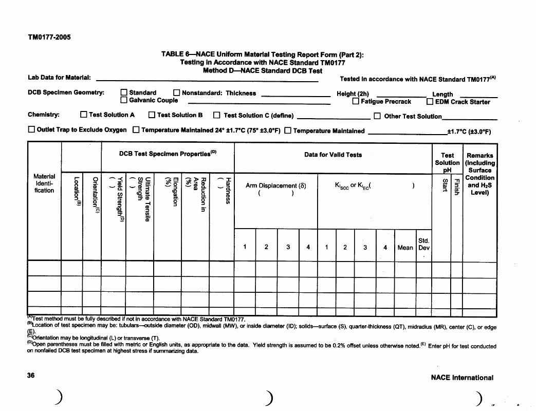
TM0177-2005
TABLE 6J{ACE Uniform Material Testlng Report Form (Part 2):Testlng in Accordance wlth NACE Standard TM017Z
ilethod D-NACE Standard DCB TestLab Data for tlaterial:
DGB speclmen Geometry: E standard El Nonstandard: Thlckness Helsht (2h)I Gakanlc Gouple
Ghemlstry: D Test Solutlon A El rest Solutlon B E Test Solution G (deflne)
E Otr0et tnp to e:rclud. (Xyg.n ! Temperahrre flalr alncd 24o tl.7'c {7t' rit.o'F} E Tcmperatuo ilalntalned
on nonfailed DCB test specimen at highest stress if summarizing data.
36
Tested in accordance with NACE Standard TM017Z6
Lengthfl fatgue Precrack D eOm Crack Starter
E Ottrer Test Soluffon_
NACE International
\),.
DGB Test Speclmen Propertles(D) Data for Valld Tests Remarks(lncludlngSurface
Conditlonand HzSLevel)
^CI'C-----!D i'dg
=o{o:'g.o
-mO\F-5(o
q)*.ot
G>ned EO' E'o6'5f
Arm Displacement (6)()

TM0177-2005
References
1. NACE MR0175/lSO(5) 15156 (latest revision),"Petroleum and natural gas industries-Materials for use inHzS-containing environments in oil and gas production"(Houston, TX: NACE).
2. European Federation of Conosion (EFC/6) Publication#16, 2nd ed., "Guidelines on Materials Requirements forCarbon and Low Alloy Steel for HzS Environments in Oiland Gas Production" (London, UK: EFC, 2002).
3. API Specification SCT/|SO 11960 (latest revision),'Specification for Casing and Tubing" (Washington, DC:APr).
4. ISO 11960 (latest revision), "Petroleum and natural gasindustries-Steel pipes for use as casing or tubing for wells"(Geneva, SwiEerland: ISO).
5. NACE Standard TM0284 (latest revision), 'Evaluationof Pipeline and Pressure Vessel Steels for Resistance toHydrogen-lnduced Cracking" (Houston, D( NACE).
6. ASTM D 1193 (latest revision),'stiandard Specificationfor Reagent Watef (West Conshohocken, PA: ASTM).
7. ASTM A 370 (latest revision), "Stiandard Test Methodsand Definitions for Mechanical Testing of Steel Produds"(West Conshohocken, PA: ASTM).
8. G. Steinbeck, W. Bruckoff, M. Kohler, H. Schlerkmann,G.A. Schmift, 'Test Methodology for Elemental Sulfur-Resistant Advanced Materials for Oil and Gas FieldEquipment," CORROSION/9S, paper no. 47 (Houston, TX:NACE, 1995).
9. Steel-lron Test Specification of the Institute for lron andSteel (VDEt/Germany) SEP 1865: "Test Methods for theEvaluation of the Conosion Perficrmance of Steels andNon-Fenous Alloys in the System: Water-HydrogenSulfid*Elemential Sulfur," German lron and Steel Institute.
10. EFC Publication #'17, 2nd ed., "Conosion ResistantAlloys for Oil and Gas Prcduction: Guidanoe on GeneralRequirements and Test Methods for HzS Service" (London,UK: EFC,2OO2r.
11. J.L. Crolet, M.R. Bonis, "How to Pressurize Autoclavesfor Conosion Testing under Carbon Dioxide and HydrogenSulfide Pressure," Conosion 56, 2 (2000): p.167.
12. J.B. Greer, "Results of Interlaboratory Sulfide StressCracking Using the NACE T-1F-9 Proposed Test Method,"MP 16,9 (1977): p.9.
13. ASTM G 49 (latest revision), "Stiandard Practice forPreparation and Use of Direct Tension Stress-ConosionTest Specimens" (West Conshohocken, PA: ASTM).
14. J.P. Fraser, G.G. Eldridge, R.S. Treseder, "Laboratoryand 'Field Methods for Quantitative Study of SulfideConosion Cracking," HzS Conosion in Oil and GasProduction-A Compilation of Classic Papers, R.N. Tuttle,R.D. Kane, eds. (Houston, TX: NACE, 1981), p. 283.Original Publication: Conosion 14, 11 (1958): p.517t.
15. ASTM G 38 (atest revision), "Standard Practice forMaking and Using GRing Stress4onosion TestSpecimens" (West Conshohocken, PA: ASTM).
16. R.B. Heady, 'Evaluation of Sulfide Conosion Crac-l<ingResistance in Low Alloy Steels," Conosion 33, 3 (1977): p.
98.
'17. D.L. Sponseller, 'lnterlaboratory Testing of SevenAlloys for SSC Resistance by the Double Gantilever BeamMethod," Conosion 48,2 (1992): p. 159.
18. S.W. Cianaldi, ?pplication of a Double CantileverBeam Specimen to Laboratory Evaluation of Sour ServiceHigh-Alloy Tubulars," CORROSION/83, paper no. 162(Houston, TX: NACE, 1983).
19. OSHA0 Rubs and Regulations (Federal Register, Vol.37, No. 202,Part ll, October 18,1972).
20. Chemical Safety Datra Sheet SD:36 (Washington, DC:Manufactu ring Chemists Association, t"'
1 950).
21. N. lrving Sax, Dangerous Properties of IndusfialMaterials (New York, NY: Reinhold Bmk Corp., 1984).
{5) hbnradonal OrgEnlzation for Sten&rdizatbn (lSO), 1rue d€ Varsmb€, C.s. Po6tel€ 56, CH.ll21 G€nsve 20,SrfliE€dand.!) Eump€an Fodoration of Co.tGion (Sodsty of Chsmicsl lndusby), In8ttJta of ir€tals, I Cadbn HouEe Tenaca, London, SWIY sDB, UK.:' Occupational Saidy and Health Admldsbadd| (OSHA), 200 CondiMion Aw. l,|w, Wshington, DE z)210.r"' lrlanutactudng Chsmist3 Association (iilcA), 1825 Conmctidrt Av6. Nw, Washington, DC 4009.
NACE International 37
TMot77-2005
q
!
Appendix A,-Safety Gonsiderations in Handling H2S Toxicity
HzS is pefiaps responsible for more industrial poisoningaccidents than is any other single chemical. A number ofthese accidents have been fatal. HzS must be handled withcaution and any experiments using it must be plannedcarefully. The OSHA maximum allowable concentration ofHzS in the air for an eight-hour work day is 20 parts peImillion (ppm), well above the level detectable by smell.rsHowever, the olfactory nerves can become deadened to theodor after exposure of 2 to 15 min, depending onconcentration, so that odor is not a completely reliablealarm system.
Briefly, the following are some of the human phpiologicalreactions to various concentrations of HzS. Erposure toconcentrations in the range of 150 to 200 ppm for prolongedperiods may cause edema of the lungs. Nausea, stomachdistress, belching, coughing, headache, dizziness, andblistering are symptoms of poisoning in this range ofconcentration. Pulmonary complications, such aspneumonia, are strong possibilities ftrom such subacutee)(posure. At 500 ppm, unconsciousness may occur in lessthan 15 min, and death within 30 min. At concentrationsabove 1,000 ppm, a single inhalation may result ininstantianeous unconsciousness, complete respir:atoryfailure, cardiac anest, and death.
Additional information on the toxicity of HzS can_le obtainedftom the Chemical Safety Data Sheet SD36a and fromDangercus Prcprties of tndustriat Materials.2l
Fire and Explosion Harards
HzS is a flammable gas and yields poisonous sulfur dioxide(SO2) as a combustion product. In addition, itrs explosivelimits range from 4 to 460/o in air. Appropriate precautionsshall be taken to prevent these hazads from developing.
Safiety Procedures During Test
All tests shall be performed in a hood wtth adequateventilation to exhaust all of the HzS. The HzS flor ratesduring the test should be kept low to minimize the quantityexhausted. A 10o/o caustic absorbent solution for effiuentgas can be used to further minimize the quantity of HzS gasexhausted. This caustic solution needs periodicreplenishing. Provision shall be made to prevent backflowof the caustic solution into the test vessel if the HzS flow isintemrpted. Suitrable safety equipment shall be used whenworking with HzS.
Because the downstream working pressure frequently risesas onosion products, debris, etc., a@umulate and interferewith regulation at low flow rates, particular attention shouldbe given to the output pressure on the pressure regulators.Gas rylinders shall be securely fastened to prevent tippingand breaking of the cylinder head. Because HzS is in liquidform in the cylinders, the higfr-pressure gauge must bechecked ftequently, because relatively little time elapsesafter the last liquid evaporates and the pressure drops ftom1.7 MPa (250 psig) to atmospheric pressure. The cylindershall be replaced by the time it reaches 0.5 to 0.7 MPa (75to 100 psig) because the regulator control may becomeenatic. Flow shall not be allowed to stop without dosing avalve or disconnecting the tubing at the test vessel becausethe test solution continues to absorb HzS and moveupstream into the flowline, regulator, and even the cylinder.A check valve in the line should prevent the problem if thevalve works properly. However, if sucfr an accident o@urs,the remaining HzS should be vented as rrapidly and safelyas possible and the manufacturer notified so that thecylinder can be given special aftention.
^
Appendix B-Explanatory Notes on EG Test Method
Reaeons for Reagent Purfi
Water impurities of major @noem are alkaline- or acid-buffering constituents that may alter the pH of the testsolution and organic and inorganic compounds that couldchange the nature of the conosion reaction. Oxidizingagents could also convert part of the HzS to solubleprcducts, such as polysulfides and polythionic acids, wtrichmay also affect the conosion process.
Alkaline materials (such as magnesium carbonate andsodium silica aluminate) are often added to (or not removedftom) commercial grades of sodium chloride to ensure free-flowing characteristics and can greatly affec.t the pH.
38
Trace orygen impurities in the purge gas are mucfr morecritical than water impurities if nitrogen (or other inert gas) iscontinuously mixed with HzS to obtain a lower partialpressure of HzS in the gas and henoe a lower HzSconcentration in the test solution. Oxidation productrs couldaccumulate, resulting in changes in conosion rate and/orhydrogen entry rate (see the paragraph below on Reasonsfor Exclusion of O4ygen).
Prcparation of Test Speclmen
All machining operations shall be perfirrmed carefully andslowly so that overheating, excessive gouging, and colduork do not alter critical physical properties of the material.

9
t
Uniform surface condition is critical to consistent SSC testresults.
Reasons for Exclusion of Oxygen
Obtaining and maintaining an environment with minimumdissolved orygen contamination is considered veryimportant because of signiftcant effects noted in field andlaboratory studies:
(1) Orygen contiamination in brines containing HzS canresult in drastic increases in conosion rates by as much astwo orders of magnitude. Generally, the o4ygen can alsoreduce hydrogen evolution and entry into the metial.
Syatematic studies of the parameters affecting thesephenomena (as they apply to EC) have not been reported inthe literature.
TM0177-2005
(2) Small amounts of orygen or ammonium polysulfide aresometimes added to aqueous refinery streams inconjunction with careful pH control near 8 to minimize bothconosion and hydrogen blistering. The effectiveness isattributed to an alteration of the conosion product.
In the absence of sufficient data to define and clarify theeffects of these phenomena on EC, all reasonableprecautions to exclude orygen shall be taken. Theprecautions cited in this standard minimize the effects oforygen with little increase in cost, difficulty, or complexity.
Cautlonary Notes
Cleaning solvents such as 1,1,1-trichloroethane, acetone,and other hydrocarbon liquids can be hazardous if thevapors are inhaled or absorbed through the skin. Manychlorinated hydrocarbon compounds are suspected ofbeing carcinogenic and should be used only with the propersafeguards.
NACE International 39

t
I
^