naca rm a55do7 estimation of incremental pitching moments due to trailing edge flaps on swept and...
TRANSCRIPT

7/27/2019 NACA RM A55DO7 Estimation of Incremental Pitching Moments Due to Trailing Edge Flaps on Swept and Triangular…
http://slidepdf.com/reader/full/naca-rm-a55do7-estimation-of-incremental-pitching-moments-due-to-trailing-edge 1/33
Copy1 7 5
RM A55D07
JH I
/.t_5I7
NACA
R E S E A R C H M E M O R A N D U M
ESTIMATION OF INCREMENTAL PITCHING MOMENTS DUE TOTRAILING-EDGE FLAPS ON SWEPT AND TRIANGULAR WINGS
By Harry A. James and Lynn W. Hunton
Ames Aeronautical LaboratoryMoffett Field, Calif.
/
CASE: FILE
COPYF D D O C U M E N T
National Defense of the United States within the meaningof the espionage laws, T itle 18, U.S.C., Secs. 793 and 794, the transmission or revelation of which In an ymanner to an u nauthorized person is prohibited by law.
N A T IO N A L A D V IS O R Y C O M M IT T E E
FO R AERONAU TICS
WASH INGTONJune 10, 1955
O N 1 D E
Restriction/Classification Cancelled
Restriction/Classification
Cancelled
Restriction/Classification Cancelled

7/27/2019 NACA RM A55DO7 Estimation of Incremental Pitching Moments Due to Trailing Edge Flaps on Swept and Triangular…
http://slidepdf.com/reader/full/naca-rm-a55do7-estimation-of-incremental-pitching-moments-due-to-trailing-edge 2/33
NACA RM A55D07ATIONAL ADVISORY COMMITTEE FOR AERONAUTICS RESEARCH MEMORANDUM
ESTIMATION OF INCREMENTAL PITCHING MOMENTS DUE TO
TRAILING-EDGE FLAPS ON SWEPT AND TRIANGULAR WINGS
By Harry A. James and Lynn W. H unton
SUMMARY
A method is presented whereby incremental pitching moments can be
estimated for swept and triangular wings having arbitrary types of
trailing-edge high-lift flaps. In the method use is made of span-loading
theory together with two-dimensional airfoil data adjusted for the effects
of sweep. The method as presented was limited to low speeds a nd small
angles of attack.
Application of the method is demonstrated for some 58 cases covering
various types of flaps on wings having a wide range of sweep, aspect
ratio, and taper ratio. For all wings, swept as well as triangular, a
mean deviation from experiment of about 0.02 in incremental pitching-
moment coefficient was found.
Two-dimensional-flap data pertinent to the general application of
the method are summarized in graphical form.
INTRODUCTION
The theory of references 1 and 2 permits the rapid determination ofthe spanwise distribution of lift, lift-curve slope, aerodynamic center,
and induced drag for wings having arbitrary plan forms and trailing-edge
flap configurations. Calculations of the pitching moment with trailing-
edge flaps deflected, however, are outside the scope of this theory since
no method of estimating the chordwise distribution of the loading due to
flap deflection was included.
The work of reference 3 has demonstrated, on a particular 1 1 5 0 swept-
back wing with flaps, how two-dimensional airfoil data and sweep theory
can be used to estimate the chordwise load distribution on a swept wing
when the spanwise load distribution is known. Once the chordwise andspanwise load distributions are know n, of course, the pitching moment can
Restriction/Classification Cancelled
Restriction/Classification Cancelled

7/27/2019 NACA RM A55DO7 Estimation of Incremental Pitching Moments Due to Trailing Edge Flaps on Swept and Triangular…
http://slidepdf.com/reader/full/naca-rm-a55do7-estimation-of-incremental-pitching-moments-due-to-trailing-edge 3/33
2ONFIDENTIALJACA EM A55D07readily be determined. The purpose of this report is to present a method
for estimating the incremental pitching moment due to trailing-edge flaps
on swept and triangular wings by using two-dimensional airfoil data and
theory in conjunction with sweep theory. To demonstrate the range of
applicability of the procedure, a study has been made wherein measuredand estimated pitching moments are compared for a w ide variety of flap
configurations on swept- and triangular-wing plan forms.
To facilitate the general application of the method, some attention
has been given to collecting from numerous sources relevant two-dimensional
data for the commonly used types of high-lift flaps, including some data
for flaps with area suction or blowing. These results have been summarized
herein in graphical form.
NOTATION
Aspect ratiobing spancocal chord1b/2 c2dy
mean aerodynamic chord, rb/2 c dyJ o
CLift coefficient lift, qS
Cmitching-moment coefficient aboutitching momentq S
section liftc 1ection lift coefficient,cC Mection pitching-moment coefficient, section pitching momentq c 2
c 1ate of change of section lift coefficient with angle of attack,per deg
cz eate of change of section lift coefficient with flap deflection,per deg
cm 5ate of change of section pitching-moment coefficient with flapdeflection, per deg
CONFIDENTIAL

7/27/2019 NACA RM A55DO7 Estimation of Incremental Pitching Moments Due to Trailing Edge Flaps on Swept and Triangular…
http://slidepdf.com/reader/full/naca-rm-a55do7-estimation-of-incremental-pitching-moments-due-to-trailing-edge 4/33
NACA B1'l A55D07ONFIDENTIAL C.P.enter of pressure, percent chordSing areaKactor equal to 3-
i o o ( A , 1 ) 2
qree-stream dynamic pressurexong itudina l coordinate from c/4to local c.p.
yateral coordinate from pla ne of symmetryangle of attack, degablap effectiveness parameter, -Ancremental valueangle of flap deflection, measured in plane parallel to plane of
symmetry, deg
angle of flap deflection for effective section measured in plane
normal to the reference sweep line, 5n = tan-l(Lan o), deg
angle of fla p deflection measured in plane normal to hinge line,
d e g
taper ratio
fraction of semispan,
Aweep angle, degSubscripts
additional lift due to angle of attackbasic lift due to camberflap or increment due to flap deflectionav verage
CONFIDENTIAL

7/27/2019 NACA RM A55DO7 Estimation of Incremental Pitching Moments Due to Trailing Edge Flaps on Swept and Triangular…
http://slidepdf.com/reader/full/naca-rm-a55do7-estimation-of-incremental-pitching-moments-due-to-trailing-edge 5/33
CONFIDENTIALACA EM A57D07Aawed flowA=owo-dimensional or equivalent two-dimensional
ThOD AND APPLICATION
The intent of this report is to supplement refe rences 1 and 2 f or
the purpose of o btaining estimates of the pitching moment with flaps
deflected.' The chordwise distribution of the loading due to flap deflec-
tion as determined from two-dimensional data are a pplied, by means of
simple-swee p theory, to swept wings and to highly tapered plan forms such
as triangular wings.
Section loadings on finite swept wings having moderate taper can,
rather successfully be rel ated to those in two-dimensional flo w through
the simple-sweep-theory rela tions by treating them as untapered wings
having a sweep ang le equal to that of the c/4 line, as demonstrated in
references 3 and 11. The primary assumption made is that each section
(streamwise) of the finite wing is assumed to behave a s that of a yawe d
infinite wing having identical streamwise geometry a nd a swee p angle
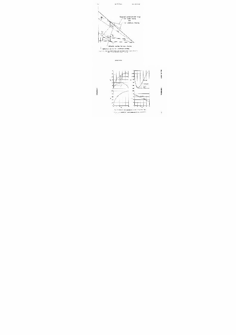
equal to that of the finite wing as illustrated in figure 1. For the
yawed infinite wing the chordwise lo ad distributions and centers of pres-
sure of streamwise sections are identical to those of sections normal to
the lea ding edge. These normal sections designated a s effe ctive sections
can be related directly to two-dimensional airfoil data through simple-
sweep-theory relations.
To attempt to apply swee p theory to determine an effe ctive section
on wings with large amounts of taper lea ds to a rather complicated section
owing to the variation in sweep angle of the constant-percent-chord lines.
Obviously, in the interest of simplicity of application, some approximation
is required for this case. Such an approximation is discussed in detail
in a subsequent section.
Untapered Swe pt Wings
A method is developed first for the simpler case involving no taper.
One effective section is used for both the add itional and basic types of
chordwise loading. The fo llowing steps are then taken for the purpose of
obtaining estimated local centers of pressure.
1 Another approach to this problem more limited in its applicability
is presented in NACA TN 16 7 1 1 entitled "Estimation of Effectiveness of
Flap-Type Controls on Sweptback Wings, " 1948, by John G. Lowry andLeslie F. Schneiter.
CONFIDENTIAL

7/27/2019 NACA RM A55DO7 Estimation of Incremental Pitching Moments Due to Trailing Edge Flaps on Swept and Triangular…
http://slidepdf.com/reader/full/naca-rm-a55do7-estimation-of-incremental-pitching-moments-due-to-trailing-edge 6/33
NACA RM A55D07ONFIDENTIAL 1. Determine the incremental spanwise load dis tribution due to flap
deflection from available theory such as re ference 1 (c j versus 9 as
shown in fig. i).
2. Obtain the centers of pressure for the sections (streamwise) of
the wing that intersect the flap as follows:
(a) Assume each finite-wing section to be equivalent to one on a
yawed infinite wing having a sweep ang le equal to that of the finite
wing.
(b) Determine the geometry of the effective section on the yawed
infinite wing. Being untapered, the flap deflection angle is the only
important parameter which differs between the streamwise and effective
sections. The flap-chord ratio remains unchang ed and the variation in
thickness can be ignored.
(c) Solve for an equivalent two-dimensional lift coefficient in
unyawed flow for each section that is being considered on the flap of
the finite wing.
C ZAC_____A=o cos2A
where CiA is the incremental lift coefficient due to flap def lection
and is equal to c1.
(d) Determine a center of pressure from two-dimensional airfoil
data or from theory of a section having the g eometry of the effective
section in (b) and at the lift coefficient obtained in (c). S ince the
section (strearnwise) of the finite wing is assumed as identical to
that on the infinite wing, the local center of pressure can be assumed
to be that found for the effective section.
3 . ssume the center of pressure for the unflapped sections of thewing to be located at the 0.25-chord line, except in the regions within
0.20 semispan of the ends of the flap. In this transition region, thecenter-of-pressure variation can be approximated by the relation
c.p. = 0.25 + K(ic.p.). The value of the constant K and the definition
of tc.p. are given in fig ure 2. This assumed variation for the center
of pressure near the ends of the flap was based primarily on the experi-
mental data shown in figure 3.
4. ith the local centers of pressure and the span loading deter-
mined, an integration of the section moments about a common axis thus
yields the incremental pitching-moment coefficient due to flap deflection
CONFIDENTIAL
7/27/2019 NACA RM A55DO7 Estimation of Incremental Pitching Moments Due to Trailing Edge Flaps on Swept and Triangular…
http://slidepdf.com/reader/full/naca-rm-a55do7-estimation-of-incremental-pitching-moments-due-to-trailing-edge 7/33
6ONFIDENTIALACA RM A55D07b / 2
CZACX d y
Tapered Swept Wings
Introducing taper into the problem rather complicates the determina-
tion of an effective section from sweep-theory concepts, owing to the
variation in sweep angle of the constant-percent-chord lines. With flaps
retracted, the loading is pri marily of the additional type and may
genera lly be assumed as concentrated close to the 0.27-chord line. With
flaps extended, however, a large portion of the loading is of the basic
(camber) type having a much more rearward center of pres sure. Since theload line for the additional loading (i.e., quarter-chord line) has been
shown (ref. i i-) to serve quite satisfactorily as the reference sweep line
to define an a verage effective section for this type of loading, it
would then a ppear re asonable to expect that the basic load line might in
similar fashion be used as a reference swee p line to define a n effective
section for the basi c type of loading. Thus, the effect of the varying
sweep angle of the constant-percent-chord lines on the chordwise loading
can be approximated in a rather simple manner. For the highly tapered
wing, two di fferent reference sw eep ang les become involved in the problem
as illustrated in figure 4. ombining t hese two loads one may derive a
local center of pressure as follows:
c A(ctbA=o(cosAb) = c1aA+ cibc,\ \__=aA+ C.P.bcj)However, it can be shown that the procedure can be simplified still fur-
thur'by use of only the basic load line as the reference sweep line for
both components of the loading (additiona l and basic). Proof that use
of only the one load line yields a n ident ical value of c.p. to that0
found by using both load lines is gi ven in Appe ndix A. Hence, the more
detailed p rocedure by parts resolves into one no more difficult than that
used for untapered w ings where only one effective section for both the
additional and basic parts of the loading was necessary.
The basic-load reference swee p line required i n this method was
determined from calculations of center of pressure of the basic load for
a plain flap using the section theory of reference 5. In the present
analysis the plain-flap theory of this reference has been used for all
flap configurations irrespective of the type. This procedure is illus-
trated in Appendix B and in figure -i-. It should be noted that t he
CONFIDENTIAL
7/27/2019 NACA RM A55DO7 Estimation of Incremental Pitching Moments Due to Trailing Edge Flaps on Swept and Triangular…
http://slidepdf.com/reader/full/naca-rm-a55do7-estimation-of-incremental-pitching-moments-due-to-trailing-edge 8/33
NACA EM A55D07ONFIDENTIAL streamwise geometry of the section considered on the finite wing is
identical to that for the fictitious yawed infinite wing; moreover, the
effective section is defined on the fictitious yawed infinite wing and
not on the finite wing.
Two-Dimensional Data
To facilitate the use of the method, a summary of some pertinent
flap parameters and flap data from two-dimensional airfoil tests and
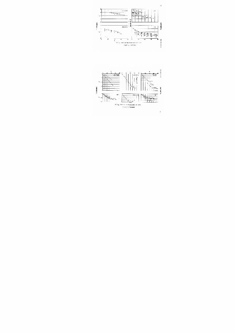
theory is given i n figure 5. Values of a6, c15, c.p.b, and c%for a
plain flap from the theory of reference 5 are shown in figure 5(a).
The values of ao and Cm f for various types of flaps given in figures 5(b)
and 5(c) were obtained from available test data of references 6 to 51.
Use of values of a and Cmf from plain-flap theory are generally appli-
cable for area-suction- and blowing-type flaps employing only sufficient
amounts of suction or blowing for maintenance of attached flow on the
flaps of the finite wing. Use of these data is demonstrated in Appendi x B.
DISCUSSION
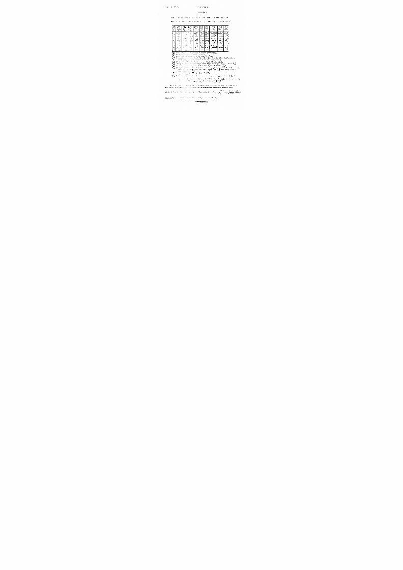
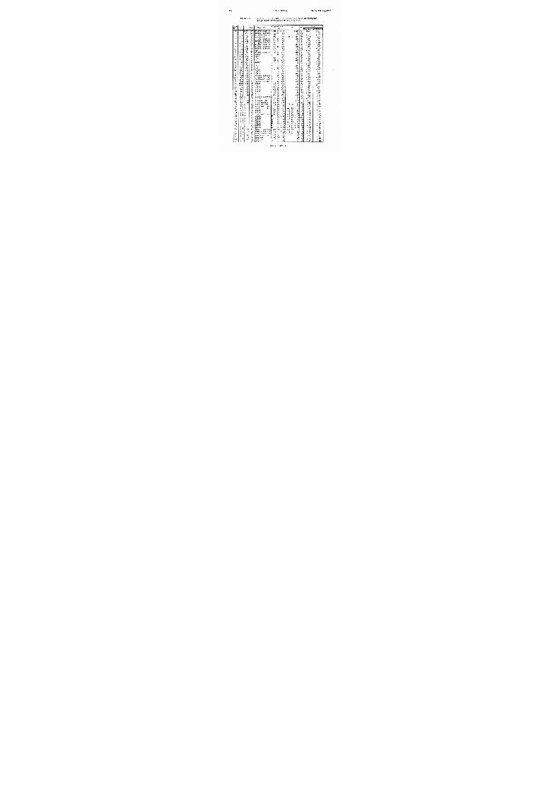
A complete summary of the calculations made of the incremental pitch-
ing moments due to flaps for some 58 cases on swept and triangular wings
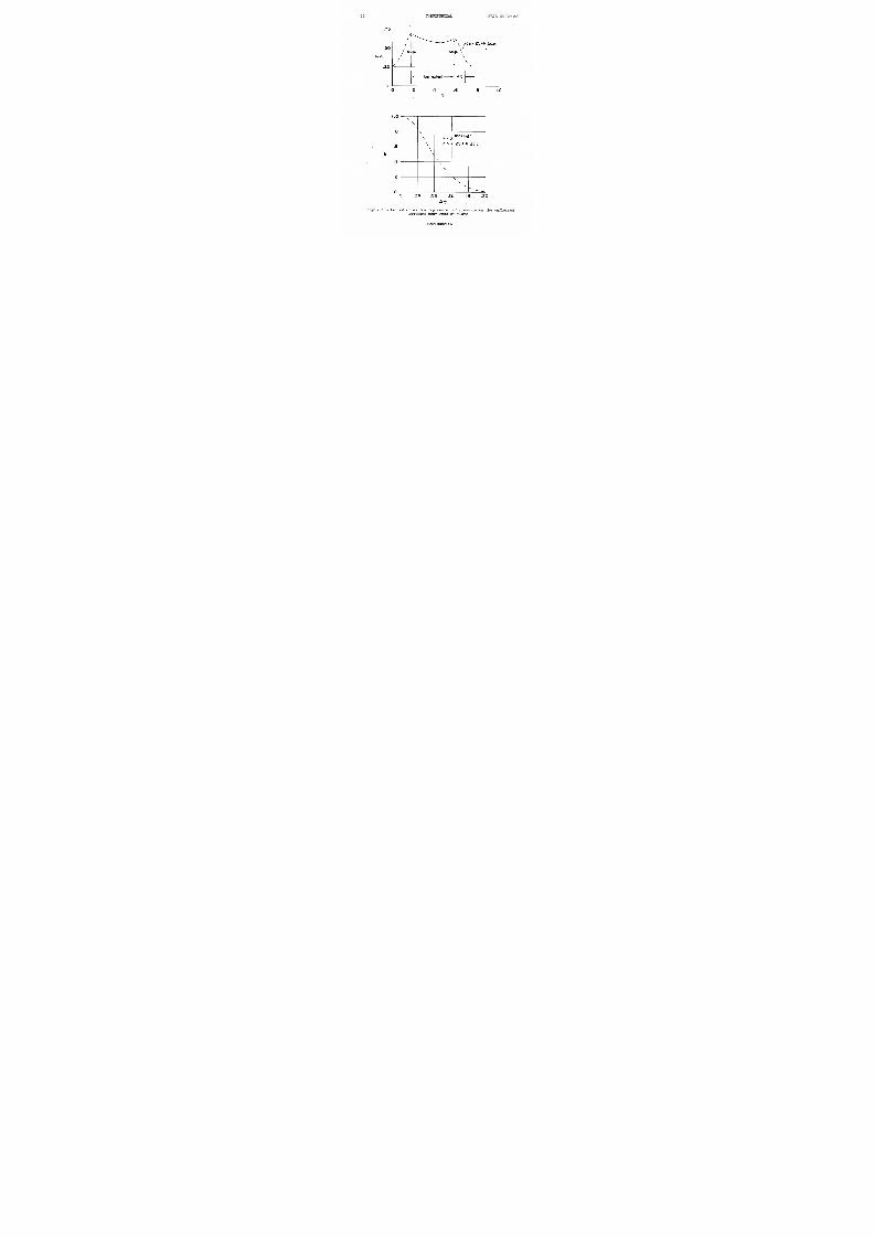
at low speed is presented in table I. The measured pitching-moment res ults
for the sample wings were obtained from references 55 to 79. A represent-
ative sampling of these results is illustrated in figures 6(a) and 6(b)
for the swept and the triangular wings, respectively. Here an attempt has
been made to show briefly some results for each of the various types of
flap configurations examined. The absolute values of lift and moment
indicated in these results were obtained by combining the calculated
increments of these quantities with the respective measure d values deter-
mined from tests of the wing with flaps retracted. The slopes of the
estimated pitching-moment curves were determined from the theory of
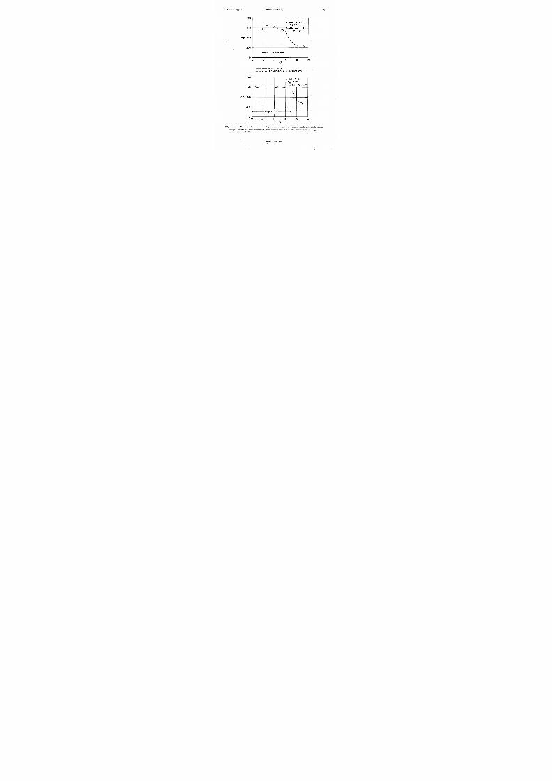
reference 2. An examination of these results shows, surprisingly enough,that little difference in accuracy exists between the swept- an d triangular-
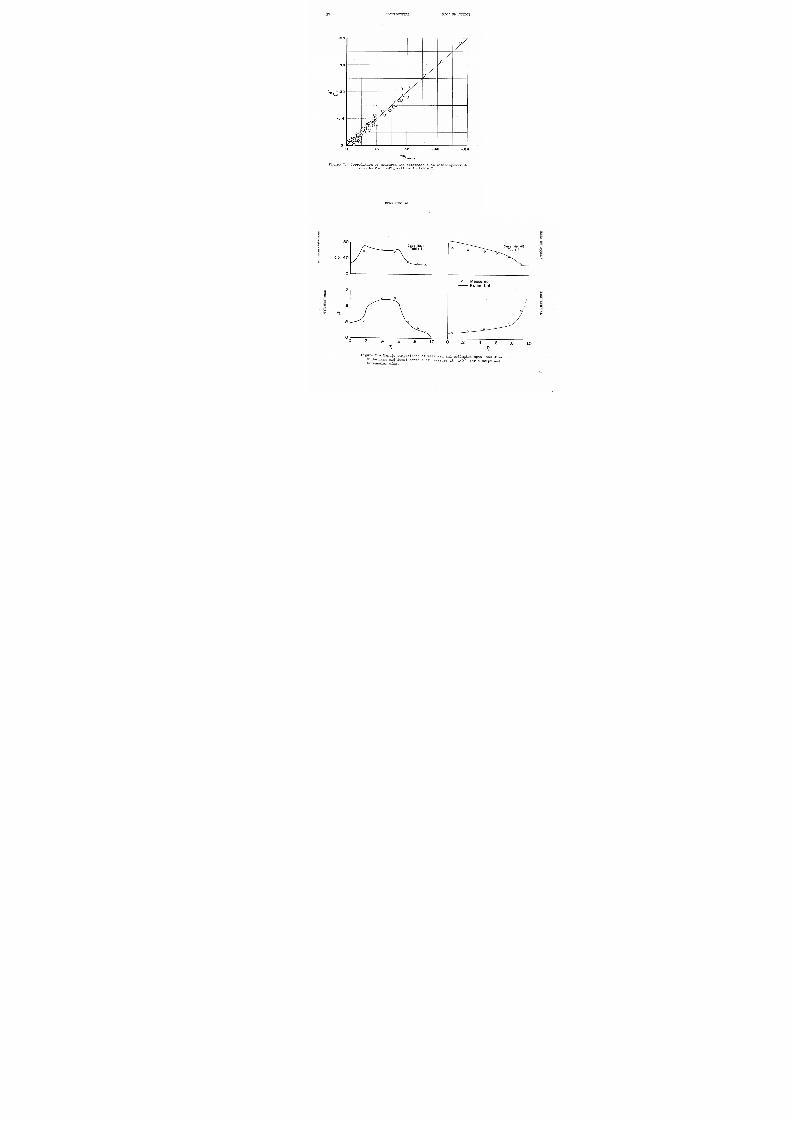
wing results. An over-all indication of the accur acy of the method for
all 58 cases can be seen in the correlation plot of figure 7 where a mean
deviation of the order of 0.02 in ACm was found. The method as presented
was limited to the low-speed, small-angle-of-attack range where the
longitudinal characteristics are essentially linear, and in the lift range
where the loading due to flap deflection can be calculated with reasonably
good accuracy. Sample comparisons of measured and estimated span load
distributions and local centers of pressure at a.=O° are shown in
figure 8 for a swept and a triangular wing.
CONFIDENTIAL

7/27/2019 NACA RM A55DO7 Estimation of Incremental Pitching Moments Due to Trailing Edge Flaps on Swept and Triangular…
http://slidepdf.com/reader/full/naca-rm-a55do7-estimation-of-incremental-pitching-moments-due-to-trailing-edge 9/33
8ONFIDENTIALACA RN A55D07CONCLUDING REMARKS
The low-speed incremental pitching-moment coefficients due to
deflection of arbitrary types of partial-span, trailing-edge, high-lift
flaps on swept and triangular wings at 00 angle of attack have been
estimated and the values correlated with test results for a wide variety
of swept- and triangular-wing configurations.. The estimates were based
on span-loading theory combined with two-dimensional airfoil data
corrected to yawed flow conditions.
The results of the study clearly showed that satisfactory estimates
of pitching-moment increments could be made for wings with sweepback
including those with large amounts of taper such as triangular plan forms.
For all wings, the estimated increments of moment coefficient deviated
from experiment by a mean value of about 0.0 2.
Ames Aeronautical Laboratory
National Advisory Committee for Aeronautics
Moffett Field, Calif., Apr. 7, 1 9 5 5
CONFIDENTIAL

7/27/2019 NACA RM A55DO7 Estimation of Incremental Pitching Moments Due to Trailing Edge Flaps on Swept and Triangular…
http://slidepdf.com/reader/full/naca-rm-a55do7-estimation-of-incremental-pitching-moments-due-to-trailing-edge 10/33
NACA RM A55D07ONFIDENTIAL APPENDIX A
USE OF THE BASIC LOAD LINE AS THE REFERENCE SWEEP LINE FOR DETERMINING LOCAL CENTERS OF PRESSURE
The general expression for the loading made up of basic and
additional components can be expressed in coefficient form as
cl = l cibA l )
Since the shape.s of the loadings are assumed to be invariant with magni-
tude, the following expression can be used to define local center ofpressure for either the finite or two-dimensional case.
c.p. = O.25() + c . P . b(-)A 2 )
The analysis by parts for the tapered swept wing indicates that
c i A =CaA=o (cos
2Aa) + c 1cos2Ab)A 3 )
and
C.P.A = O.27() + c.P. b(cAA u )
It is the intent now to show that only the value of Ab is required in
the determination of c.p.
For a particular flap-chord ratio and deflection, c ZbA=o n d
can be determined from theory or two-dimensional data from which the
basic loading for the finite wing section can be expressed as
c 1cbAbA5AbA 7 )
which then defines the additional loading
CC ibA6 )aA
CONFIDENTIAL
7/27/2019 NACA RM A55DO7 Estimation of Incremental Pitching Moments Due to Trailing Edge Flaps on Swept and Triangular…
http://slidepdf.com/reader/full/naca-rm-a55do7-estimation-of-incremental-pitching-moments-due-to-trailing-edge 11/33
10ONFIDENTIALACA RM A55D07Substitution of equations (A5) and (A6) into equation .(A l - - ) g i v e s
C j b 0S2Ab
C.P.A = (1(C.P'b - 0.25) + 0.25A 7 )
The two-dimensional pitching-moment coefficient may be expressed as
_ c m A _ - olb A = O (c.p. b - 0 . 2 5 )A 8 )
Substitution of equation (A8) into (A7) gives
C . P.
A
= 0.25 - (crnA).A 9 )
which, it can be seen, does not involve the value of the additional lift
reference line Aa.
CONFIDENTIAL
7/27/2019 NACA RM A55DO7 Estimation of Incremental Pitching Moments Due to Trailing Edge Flaps on Swept and Triangular…
http://slidepdf.com/reader/full/naca-rm-a55do7-estimation-of-incremental-pitching-moments-due-to-trailing-edge 12/33
NACA RN A55D07ONFIDENTIAL1APPENDIX B
SAMPLE CALCULATIONS FOR AN ASP ECT-RATIO-2 TRIANGULAR WING
WITH A FULL-SPAN.
, CONSTANT-CHORD, PLAIN FLAP DEFLECTED iO°
T Ir0.107
Cf/C a C2 C.p. b Ab, 6j C
®
CiAC•P•
0 0.39 0.137 0.69 31.0 11.6 -0.1116 o . 1 8 1 + 0 . 8 6
. 1 .112 .42 .143 .69 31. 4 11. 7 -.1137 .197 . 8 3
. 2 .130 . 1 + 5 .160 . 6 8 32.0 11.8 -.1197 .222 . 7 9
. 3 .150. 1 + 8
.177 .67 33.3 11.9 -.1257 .257. 7 1 +
. 1 + .175 .52 .203 . 6 6 33.8 12. 0 -.1307 .295 . 6 9
. 5 .210 . 7 6 . 2 1 + 0 . 6 1 + 3 1 + . 5 12. 1 -.1386 . 3 5 1 + . 6 1 +
. 6 .270 .63 .265 .61 37.0 12.5 - . 1 1 + 5 0 . 1 + 1 6 . 6 0
. 7 .360 .70 .313 .57 1 + 0 . 0 13.0 -.1388 .532 . 7 1
. 8 .530 . 8 1 + .379 .8 1 + 6 . 0 1 1 + . 3 -.1106 .788 . 3 9
. 9 1. 000 1. 00 .610 0 --- . 2 5
1.0 1.000 1.00 0-1 Intervals of 0.1 will suffice generally.2 From streamwise fla p geometry.
Theoretical values from figure 5(a).
Incremental spa n load distribution due to flap deflection.from available methods such as reference 1.
(3 Pla in-flap basic load c.p. from figure 5(a).
Sweep of the constant-percent line through c.p.b f r o m
© 8n = tan - '(tan 8/cos Ab) = tan - '(tan 100/cos
From two-dimensional da ta or theory (theory used in this ca se),
such as in fie 5(a), for cf/c in G and flap deflec-
tion 8- in
C iA = c z A/ cosAb =Ø/cos2 ®
From two-dimensional data or theory at CiArom ®, forCf/c innd flap deflectipn8 in 0 ; or computed by
c.p. = 0.25 - (cmf/cZA ) = 0.25 - 6 / ( D At this point, several of the a ccepted procedures may be used with
the above information to obtain an incremental pitching-moment coef-
ficient due to flap deflection. The relation Cm f =
from reference 80 is sometimes used; or more simp ly
f o1.0 C2\f'2r. . ./4cav)b)
CONFIDENTIAL

7/27/2019 NACA RM A55DO7 Estimation of Incremental Pitching Moments Due to Trailing Edge Flaps on Swept and Triangular…
http://slidepdf.com/reader/full/naca-rm-a55do7-estimation-of-incremental-pitching-moments-due-to-trailing-edge 13/33
12ONFIDENTIALACA RM A55D07b / 2MfrC I u f =y = -CLf *
U0
(x is the distance to E/4 from the wing center of pressure) which for
the above example was found to be:
Cmf = -o.2o6(l) = - 0.098
Configurations having constant-percent-chord flaps naturally have
singul ar valu es of,ndnd, consequently,the computations are reduced considerably.
CONFIDENTIAL

7/27/2019 NACA RM A55DO7 Estimation of Incremental Pitching Moments Due to Trailing Edge Flaps on Swept and Triangular…
http://slidepdf.com/reader/full/naca-rm-a55do7-estimation-of-incremental-pitching-moments-due-to-trailing-edge 14/33

7/27/2019 NACA RM A55DO7 Estimation of Incremental Pitching Moments Due to Trailing Edge Flaps on Swept and Triangular…
http://slidepdf.com/reader/full/naca-rm-a55do7-estimation-of-incremental-pitching-moments-due-to-trailing-edge 15/33
14ONFIDENTIALACA RM .A55D0713. Rogallo, Francis M.: Collection of Balanced Aileron Test Data.
NACA WE L-419, 191. (Formerly NACA ACR ll.Ali)
1 4 . Sears,. Richard I.: Wind-Tunnel Data on the Aerodynamic Character-
istics of Airplane Control Surfaces. NACA WR L-663, 1943.
(Formerly NACA ACE 3L08)
1 5 . Swanson, Robert S .J.
and Crandall, Stewart M.: Analysis of Available
Data on the Effectiveness of Ailerons Without Exposed Overhand
Balance. NACA WE L-17131 1911. (Formerly NACA ACE L4E0l)
1 6 . Street, William G., and Ames, Milton B., Jr.: Pressure-Distribution
Investigation of an NACA 0009 Airfoil With a 50-Percent-Chord
Plain Flap and Three Tabs. NACA TN 734 1 1 9 3 9 .
1 7 . Sears, Richard I., and Ames, Milton B., Jr.: Pressure-Distribution
Investigation of an NACA 0 00 9 Airfoil With a 30-Percent-Chord
Plain Flap and Three Tabs. NACA TN 75 9, 1940 .
18. Ames, Milton B., Jr., and Sears, Richard I.: Determination of
Control-Surface Characteristics from NACA Plain-Flap and Tab Data.
NACA Rep. 721, 1941.
1 9 . Langley Research Department: Summary of Lateral-Control Research.
Compiled by Thomas A. Toll. NACA TN 1245, 1947.
20. Braslow, Albert L.: Two-Dimensional Wind-Tunnel Investigation of
Sealed 0.22-Airfoil-Chord Internally-Balanced Ailerons of Different
Contour on an NACA 6 5 ( 112 ) _ 21 3 Airfoil. NACA TN 1099, 1 946.
2 1 . Lockwood, Vernard E..: Wind-Tunnel Investigation of Control-Surface
Characteristics. XVII - Beveled-Trailing-Edge Flaps of 0.20, 0.30,
and 0 . 1 1 . 0 Airfoil Chord on an NACA 0009 Airfoil. NACA WR L-666,
1944. (Formerly NACA ACR I)4D12)
2 2 . Rose, Leonard M., and Altman, John M.: Low-Speed Experimental Inves-
tigation of a Thin Faired, Double-Wedge Airfoil Section With Noseand Trailing-Edge Flaps. NACA TN 1934, 1 9 4 9 .
2 3. Wenzinger, Carl Joseph, and Delano, James B.: Pressure Distribution
Over an NACA 23012 Airfoil With a Slotted and a Plain Flap.
NACA Rep. 633, 1 9 3 8 .
2 4 . Weick, Fred E., and Jones, Robert T.: Resume'uni and Analysis of NACA
Lateral Control Research. NACA R ep. 60 5, 1937.
2 5 . Purser, Paul E., and Johnson, Harold S.: Effects of Trailing-Edge
Modifications on Pitching-Moment Characteristics of Airfoils.NACA WR L-664, 19411.. (Formerly NACA CB L4130)
CONFIDENTIAL

7/27/2019 NACA RM A55DO7 Estimation of Incremental Pitching Moments Due to Trailing Edge Flaps on Swept and Triangular…
http://slidepdf.com/reader/full/naca-rm-a55do7-estimation-of-incremental-pitching-moments-due-to-trailing-edge 16/33
NACA RM A57D07ONFIDENTIAL726. Klein, Milton M.: Pressure Distribution and Forc e Tests of an NACA
65-210 Airfoil Section With a 70-Percent-Chord Plain Flap. NACA
TN 116, 191v7.
27. Holtzclaw, Ralph W., and Weisman, Yale: Wind-Tunnel Investigation
of the Effects of Slot Shape and Flap Location on the Character-
istics of a Low-Drag Airfoil Equipped With a 0.25- Chord Slotted
Flap. NACA WR A-80 1 1944. (Formerly NACA MR ALi-L28)
28. Wenzinger, Carl Joseph, and Harris, Thomas A.: Wind-Tunnel Investi-
gation of an NACA 23012 Airfoil With V arious Arrangements of
Slotted Flaps. NACA Rep. 677, 1 9 3 9 .
29. Holtzclaw, Ralph W., and Dods, Jules B., Jr.: Wind-Tunnel Investi-
gation of Drooped Ailerons on a 16-Percent-Thick Low-Drag Airfoil.
NACA TN 1386, 1947.
30. Holtzclaw, Ralph W.: Wind-Tunnel Investigat ion of the Effects of
Spoilers on the Characteristics of a Low-Drag Airfoil Equipped With
a 0.27-Chord Slotted Flap. NACA WR A -9 2 , 1945. (Formerly NACA
MR A5G23)
31. Abbott, Ira H.: Pressure-Distribution Measurements of Two Airfoil
Models With Fowler Flaps Submitted by Consolidated Vultee Aircraft
Corporation as Alternative Wing Sections of the XB-32 Airplane.
NACA WR L-700, 1942. (Formerly CNR for Army, Jan. 2 9 , 1 9 4 2 )
32. Underwood, William J., and Abbott, Frank T.: Test of NACA 66,2-116,
= 0.6 Airfoil Section Fitted With Pressure Balance and Slotted
Flaps for the Wing of the XP-63. NACA WR L-701, 1912. ( Formerly
NACA CMR for AAF Mat. Corn., May 23, 1942)
33. Harris, Thomas A.: Wind-Tunnel Investigation of an NACA 23012 Air-
foil With Two Arrangements of a Wide-Chord Slott ed Flap. NACA
TN 715, 1 9 3 9 .
34. Duschik, Frank: Wind-Tunnel Investigation With Two Arrangements ofan NACA 23021 Airfoil With Two Arrangements of a 40-Percent-Chord
Slotted Flap. NACA.TN 728, 1939.
35. Abbott, Ira H .J.
and Fulliner, • Felicien F., Jr.: Wind-Tunnel Investi-
gation of an NACA 63,4-4 20 Section With 25-Percent - Cho rd SlottedFlap. NACA ACR 3121, 19113.
36. Goodwin, Myron D.: Single-Slotted Trailing-Edge Flap Combined With
Plain or Slotted Leading-Edge Flap. Wright Air Development Center
TB 6356 1 July 1953, pt. 3.
CONFIDENTIAL

7/27/2019 NACA RM A55DO7 Estimation of Incremental Pitching Moments Due to Trailing Edge Flaps on Swept and Triangular…
http://slidepdf.com/reader/full/naca-rm-a55do7-estimation-of-incremental-pitching-moments-due-to-trailing-edge 17/33
16ONFIDENTIALACA RM A55D0737. Wenzinger, Carl Joseph,and Gauvain, William E.: Wind-Tunnel
Investigation of an NACA 23012 Airfoil With a Slotted Flap and
Three Types of Auxiliary Flaps. NACA Rep. 679, 1939.
38. Purser, Paul Emil, Fischel, Jack, and Riebe, John M.: Wind-Tunnel
Investigation of an NACA 23012 Airfoil With a 0 .30-Airfoil-Chord
Double-Slotted Flap. NACA WR L-469 , 1943. (Formerly NACA
ARR 3 1 , 1 0 )
39. Quinn, John H., Jr.: Wind-Tunnel Investigation of the NACA 651_1I21
Airfoil Section With a Double-Slotted Flap and Boundary-Layer
Control by Suction. NACA TN 1395, 1947.
h O. Cahill, Jones F.: Two-Dimensional Wind-Tunnel Investigation of FourTypes of High-Lift Flaps on an NACA 65-21 0 Airfoil Section. NACATN 1191 3 , 1 9 4 7 .
41. Cahill, Jones F., and Raciscz, Stanley F.: Wind-Tunnel Investigation
of Seven Thin NACA Airfoil Sections to Determine Optimum Double-
Slotted-Flap Configurations. NACA TN 1 5 1 1 . 5 , 1 9 4 8 .
1 1.2. Bogdonoff, Seymour M.: Wind-Tunnel Investigation of a Low-DragAirfoil Section With a Double-Slotted Flap. NACA WR L-697, 1943.
(Formerly NACA ACR 3120)
43. Visconti, F.: Wind-Tunnel Investigation of Air Loads Over a Double-
Slotted Flap on the NACA 65(216)-215, a = 8, Airfoil Section.
NACA EM L7A30, 1947.
1 1 . 1 1.. Braslow, A. L., and Loftin, L. K., Jr.: Two-Dimensional Wind-TunnelInvestigation of an Approximately 14-Percent-Thick NACA 66 -Series-
Type Airfoil Section With a Double Slotted Flap. NACA TN 1110, 1946.
1 1.5. Kelly, John A., and Hayter, Nora-Lee F.: Lift and Pitching Momentat Low Speeds of the NACA 64AO10 Airfoil Section Equipped With
Various Combinations of a Leading-Edge Slat, Leading-Edge Flap,
Split Flap, and Double-Slotted Flap. NACA TN 3 00 7 , 1 9 5 3 .
46 . Abbott, Ira H., and Greenberg, Henry: Tests in the Variable-Density
Wind Tunnel of the NACA 23012 Airfoil With Plain and Split Flaps.
NACA Rep. 661, 1949.
47 . Wenzinger, Carl J., and Harris, Thomas A.: Wind-Tunnel Investigation
of the NACA 23012 123021, and 23030 Airfoils With Various Sizes of
Split Flaps. NACA Rep. 668, 1939.
18. Schuldenfrei, Marvin J.: Wind-Tunnel Investigation of an NACA 23012Airfoil With a Handley-Page Slat and Two Flap Arrangements. NACA
WR L-261 5 0 1942.
CONFIDENTIAL

7/27/2019 NACA RM A55DO7 Estimation of Incremental Pitching Moments Due to Trailing Edge Flaps on Swept and Triangular…
http://slidepdf.com/reader/full/naca-rm-a55do7-estimation-of-incremental-pitching-moments-due-to-trailing-edge 18/33
I'TACA PM A55D07ONFIDENTIAL749. Harris, Thomas A., and Purser, Paul E.: Wind-Tunnel Investigation
of an NACA 23012 Airfoil With Two Sizes of Balanced Split Flaps.
NACA WR L-441 3 1 1940. (Formerly NAC A AC R, Nov. 1940)
50. Schuldenfrei, Marvin J.: Wind-Tunnel Investigation of an NACA 23012
Airfoil With a Handley-Page Slat and Two Flap Arrangements. NACA
WE L-261, 1942. (Formerly NACA ABE, Feb. 1942)
51. Gauvain, William E.: Wind-Tunnel Tests of a C lark Y Wing With
"Maxwell" Leading-Edge Slats. NACA TN 5981 1 9 3 7 .
52. McKee, Paul 5., Jr.: Plain and Slotted Leading-Edge Flaps With a
C onventional Split Trailing-Edge Flap. Wright A ir D evelopment
Center TB 6356, Apr. 1951, pt. 1.
53. Regenscheit, B.: Measurements on an NACA 23015 Wing With Suction
Flaps of 10-Percent and 15-Percent Chord. MOS Volkenrode,
vol. 40, British Rep. & Trans. 482, 1946.
Harkleroad, Edgar L., and Murphy, R. D.: Two-dimensional Wind-
Tunnel Tests of a Model Of an F9F-5 Airplane Wing Section Using
a High-Speed Jet Blowing Over the Flap. Part I - Tests of a
6-Foot Chord Model. Bureau of Aeronautics, Navy Dept., TED No.
TMB DE-3134, May 1953.
55. Franks, Ralph W.: T ests in the Amesy 80-Foot Wind Tunnel ofTwo Airplane Models Having Aspect Ratio 2 Trapezoidal Wings of
Taper Ratio of 0.33 and 0.20. NACA EM A521,16 1 1 9 5 3 -
56. Franks, Ralph W.: Tests in the Ames 1 40 by 80 -Foot Wind Tunnel ofan A irplane Model With an A spect Ratio 4 Triangular Wing and an
All-M ovable Horizontal T ail - High Lift D evices and Lateral
Controls. NACA PM A5 2K13, 1953.
57. Koenig, David G.: Tests in the Ames h O- by 80-Foot Wind Tunnel ofan A irplane Configuration With an Aspect Ratio 3 T riangular Wing
and an All-Movable Horizontal Tail - Longitudinal and Lateral
Characteristics. NACA EM A52L15, 1953.
8. Graham, David: Chordwise and Spanwise Loadings Measured at Low
Speeds on a Large Triangular Wing Having an Aspect Ratio 2 and a
Thin, Subsonic-Type Airfoil Section. NACA EM A50A04a, 1950.
59. Graham, David, and Koenig, David G.: Tests in the Ames 40- by
80-Foot Wind Tunnel of an Airplane Configuration With an Aspect
Ratio 2 T riangular Wing and an All-M ovable Horizontal T ail -
Longitudinal Characteristics. NACA EM A5 1B21, 1951.
CONFIDENTIAL

7/27/2019 NACA RM A55DO7 Estimation of Incremental Pitching Moments Due to Trailing Edge Flaps on Swept and Triangular…
http://slidepdf.com/reader/full/naca-rm-a55do7-estimation-of-incremental-pitching-moments-due-to-trailing-edge 19/33
18ONFIDENTIALACA EM A75D0760. Smith, Donald W., and Reed, Verlin D.: Subsonic Static Longitudinal
Stability and Control Characteristics of a Wing-Body- Combination
Having a Pointed Wing of Aspect Ratio 2 With Constant-Percent-
Chord Elevons. NACA EM A53C20, 1 9 7 3 .
61. Riebe, John M., and MacLeod, Richard G.: Low-Speed Wind-Tunnel
Investigation of a Thin 600 elta Wing With Double-Slotted,
Single-Slotted, Plain and Split Flaps. NACA EM L52J29, 1953.
62. Whittle, Edward F., Jr., and Lovell, J. Calvin: Full-Scale Inves-
tigation of an Equilateral Triangular Wing Having 10-Percent-
Thick Biconvex Airfoil Sections. NACA EN L8G05, 1948.
63. Fink, Marvin P., and Cocke, Bennie W.: A Low-Speed Investigation
of the Aerodynamic, Control, and Hinge-Moment Characteristics of
Two Types of Controls and Balancing Tabs on a Large-Scale Thin
Delta-Wing-Fuselage Model. NACA RN L54B03, 1954.
64. Kelly, Mark W.: Low-Speed Aerodynamic Characteristics of a Large-
Scale 60 0 Swept-Back Wing With High-Lift Devices. NACA EM A5 2A14a,
1 9 5 2 .
6. Maki, Ralph W., and Embry, Ursel R.: Effects of High-Lift Devices
and Horizontal-Tail Location on the Low-Speed Characteristics of
a Large-Scale 45 0 Swept-Wing Airplane Configuration. NACA EM
A5E10, 1954.
66. Cook, Woodrow L., Holzhauser, Curt A., and Kelly, Mark W.: The Use
of Area Suction for the Purpose of Improving Trailing-Edge Flap
Effectiveness on a 35 0 Swept Wing. NACARM A53E06, 195 3.
67. Kelly, Mark W., and Tolhurst William H.: The Use of Area Suction to
Increase the Effectiveness of a Trailing-Edge Flap on a Triangular
Wing of Aspect Ratio 2. NACA PM A5 1 A25, 1954.
68. Mollenberg, Ernest F., and Spooner, Stanley H.: Low-Speed Investi-
gation of the Effects of Single-Slotted and Double-Slotted' Flapson a 1 1 . 7 . 7 0 Swept-Back Wing-Fuselage Combination at a Reynolds
Number of 6x10 6 . NACA RM L51E2 1 1 ., 1 9 5 1 .
69. Koven, William, and Graham, Robert R.: Wind-Tunnel Investigation of
High-Lift and Stall-Control Devices on a370
Swept-Back Wing of
Aspect Ratio 6 at High Reynolds Numbers. NACA EM L8D29, 1948.
70. Barnett, U. Reed, Jr., and Lipson, Stanley: Effects of Several High-
Lift and Stall-Control Devices on the Aerodynamic Characteristics
of a Semi-Span 1 1 . 9 ° Swept-Back Wing. NACA RN L52D17a, 1952.
CONFIDENTIAL
7/27/2019 NACA RM A55DO7 Estimation of Incremental Pitching Moments Due to Trailing Edge Flaps on Swept and Triangular…
http://slidepdf.com/reader/full/naca-rm-a55do7-estimation-of-incremental-pitching-moments-due-to-trailing-edge 20/33
NACA EM A55 D0 7ONFIDENTIAL971. Guryansky, Eugene R., and Lipson, Stanley: Effect of High-Lift
Devices on the Longitudinal and Lateral Characteristics of a 45 0
Swept-Back Wing With Symmetrical Circular-Arc Sections. NACA
EM L8D06, 1948 .
72. Schuldenfrei, Marvin J., Coinisarow, Paul, and Goodson, Kenneth W.:
Stability and Control Characteristics of a Complete Airplane Model
Having a Wing With Quarter-Chord Line Swept Back 400, A s p e c t
Ratio 2.50 and Taper Ratio 0.42. NACA TN 2 1 1 . 8 2 , 1 9 5 1 .
73. Sivells, James C., and Spooner, Stanley H.: Investigation in the
Langley 19-Foot Pressure Tunnel of Two Wings of NACA 65-21 0 and
64 -210 Airfoil Sections With Various Types of Flaps. NACA Rep.
942, 1949.
7 1 4.. Tinling, Bruce E., and Lopez, Armando E.: The Effects of Nacelles
and of Extended Split Flaps on the Longitudinal Characteristics of
a Wing-Fuselage-Tail Combination Having a Wing With 1 I 0 0 of Sweep-
back and an Aspect Ratio of 10. NACA EM A53D06 1 1 9 5 3 .
75 . Graham, David, and Koenig, David G.: Tests in the Ames 0- by
80-Foot Wind Tunnel of an Airplane Configuration With an Aspect
Ratio 2 Triangular Wing and an All-Movable Horizontal Tail -
Lateral Characteristics. NACA EM A51L03, 1 95 2.
6. Graham, David: The Low-Speed Lift and Drag Characteristics of aSeries of Airplane Models Having Triangular or Modified Triangular
Wings. NACA EM A53D14, 195 3.
7 7 . Anderson, Adrien E.: Chordwise and Spanwise Loadings Measured at
Low Speed on Large Triangular Wings. NACA EM A9B17 , 19 49.
7 8 . Lowry, G., and Schneiter, Leslie E.: Inv estigation at Low Speed of
the Longitudinal Stability Characteristics of a 60 0 Swept-Back
Tapered Low-Drag Wing. NACA TN 1284, 1 947 .
7 9 . Pratt, George L., and Shields, E. Rousseau: Low-Speed LongitudinalCharacteristics of a 45 0 Swept-Back Wing of Aspect Ratio 8 With
High-Lift and Stall Control Devices at Reynolds Numbers from
1,500,000 to 11,8 00,000. NACA EM L51JO I 1. , 1 9 7 2 .
8 0. Kelly, H. Neale: The Calculated and Experimental Incremental Loads
and Moments Produced by Split Flaps of Various Spans and Spanwise
Locations on a 450 Swept-Back Wing of Aspect Ratio 8 ACA EM
L53F12, 1953.
CONFIDENTIAL
7/27/2019 NACA RM A55DO7 Estimation of Incremental Pitching Moments Due to Trailing Edge Flaps on Swept and Triangular…
http://slidepdf.com/reader/full/naca-rm-a55do7-estimation-of-incremental-pitching-moments-due-to-trailing-edge 21/33

7/27/2019 NACA RM A55DO7 Estimation of Incremental Pitching Moments Due to Trailing Edge Flaps on Swept and Triangular…
http://slidepdf.com/reader/full/naca-rm-a55do7-estimation-of-incremental-pitching-moments-due-to-trailing-edge 22/33
N i f l • g
2 1ACA EM A55D07ONFIDENTIALo. . 0
A
Effective sections
Infinite wing
c.p
Flap
C
CLoadings assumed on
yawed infinite wing
Theoretical loadingon finite wing due
c1/ o flap deflection
0.01 1
Figure 1.- Theoretical loading for untapered wing with trailing-edge flap.
CONFIDENTIAL
7/27/2019 NACA RM A55DO7 Estimation of Incremental Pitching Moments Due to Trailing Edge Flaps on Swept and Triangular…
http://slidepdf.com/reader/full/naca-rm-a55do7-estimation-of-incremental-pitching-moments-due-to-trailing-edge 23/33
22 CONFIDENTIALACA RM A75D07Vc.p . - . 25+k ,ac .p .
àC.p.C.P./
.25'
f la p e x t e n t
00268. 01 . 0
. 8
. 6
k
. 4
. 2
00040 81 21 62 0
1 7
Figure 2.- Method of estimating center of pressure on the unflapped sections near ends of flaps.
N
\\
k-IOO(Ai)C. P . = . 2 5 + k Ac.p.
\
\
\
\
\
N
CONFIDENTIAL
7/27/2019 NACA RM A55DO7 Estimation of Incremental Pitching Moments Due to Trailing Edge Flaps on Swept and Triangular…
http://slidepdf.com/reader/full/naca-rm-a55do7-estimation-of-incremental-pitching-moments-due-to-trailing-edge 24/33
NACA RM A55D07ONFIDENTIAL3.80
.60
C.P. .40
.2 0
=6.OO.54 5 0
)oubte slotted flop
8'5 °
'I
0
- lap extent—.I
I Si2468. 07 7
—0---- Measured
- --- Assumed c.p. variation
.80
60
C.P. .40
20
0268. 07 )
Figure 3 . - Measured centers of pressure on two wings with partial-span
flaps showing the assumed variation used in the transition region
near ends of flaps.
=2.O=OPlain flop, 8' =220-------o---_
0 ',
Flap extent -CONFIDENTIAL
7/27/2019 NACA RM A55DO7 Estimation of Incremental Pitching Moments Due to Trailing Edge Flaps on Swept and Triangular…
http://slidepdf.com/reader/full/naca-rm-a55do7-estimation-of-incremental-pitching-moments-due-to-trailing-edge 25/33
24ONFIDENTIALACA RN A55D07/ 0 0
AG
Ab
I N C.P.b
A s s u m e d
f o r
for
yawe d infinite w ings
basic loading
a n d
addit ional loading
iiEffe c t iv e s e c t io n fo r b a s ic l o a d ing
E f fe ct ive s e ct io n f o r a d d i tio na l lo a d ing
Figure 4.-Tapered swept wing with reference sweep lines shown for additional- and basic-type loading.
CONFIDENTIAL
7/27/2019 NACA RM A55DO7 Estimation of Incremental Pitching Moments Due to Trailing Edge Flaps on Swept and Triangular…
http://slidepdf.com/reader/full/naca-rm-a55do7-estimation-of-incremental-pitching-moments-due-to-trailing-edge 26/33
t
co
d0
1E
_
i-
.J0CD
2C.0
H)
c
aE
.r-13 P,
(31HPi
o CH,-4
C
ca
I
a
H cd rd
Cl
a-P CjdHrdC)0
H C3P
C)rdco Hl5Cl
U -
U-l
a10a
)'-
I
I
0
0
0
00
0
o
w
-c
C
N
.
w
CD
0
c
.j
0
0
0
0 0000q o00—
I
I
l•
Ia.
0
U
E U
CONFIDENTIAL

7/27/2019 NACA RM A55DO7 Estimation of Incremental Pitching Moments Due to Trailing Edge Flaps on Swept and Triangular…
http://slidepdf.com/reader/full/naca-rm-a55do7-estimation-of-incremental-pitching-moments-due-to-trailing-edge 27/33
7/27/2019 NACA RM A55DO7 Estimation of Incremental Pitching Moments Due to Trailing Edge Flaps on Swept and Triangular…
http://slidepdf.com/reader/full/naca-rm-a55do7-estimation-of-incremental-pitching-moments-due-to-trailing-edge 28/33
MEN
Ha1
PAP,
1 E00
cd ca
+ co ci
HrdCdzdo
•HC'C))
()oo0
r1rd+U)0rdiU)C'C
d
rO 0
0
—4I
e
-
/400to
.a0000(0
6?0c
..J
000(006
0c'J 0
(D
OD
0
I
I
E
U
E
U
CONFIDENTIAL

7/27/2019 NACA RM A55DO7 Estimation of Incremental Pitching Moments Due to Trailing Edge Flaps on Swept and Triangular…
http://slidepdf.com/reader/full/naca-rm-a55do7-estimation-of-incremental-pitching-moments-due-to-trailing-edge 29/33
I
.E
1:-0_I
1
CD -•H
o- c3
-
D-
)OCl
i•
11)
00
o
q-
A
0
)
.u
c
E
q
A
C+
z
+D
cd
oE0
r1
)
cd C)
Hp•1
o
/1
\TW
00E
E0 OD
;n
0w0o"C0U)-
'?.g totoOD
ccJ(0
C)
0
CODNA

7/27/2019 NACA RM A55DO7 Estimation of Incremental Pitching Moments Due to Trailing Edge Flaps on Swept and Triangular…
http://slidepdf.com/reader/full/naca-rm-a55do7-estimation-of-incremental-pitching-moments-due-to-trailing-edge 30/33
0
OD
1C
.5L
ccio
VI)C-
cIv
JEc
0
o_to
E
0a,00
2
C)
CONFIDENTIAL

7/27/2019 NACA RM A55DO7 Estimation of Incremental Pitching Moments Due to Trailing Edge Flaps on Swept and Triangular…
http://slidepdf.com/reader/full/naca-rm-a55do7-estimation-of-incremental-pitching-moments-due-to-trailing-edge 31/33
30ONFIDENTIALACA RM A55D07
—.64
—.48
Cm —.32
rest
—.16
0.1 6.32.48.64Cm
moos
Figure 7.- Correlation of measured and estimated flap pitching -moment results for configurations in table T.
0
CONFIDENTIAL

7/27/2019 NACA RM A55DO7 Estimation of Incremental Pitching Moments Due to Trailing Edge Flaps on Swept and Triangular…
http://slidepdf.com/reader/full/naca-rm-a55do7-estimation-of-incremental-pitching-moments-due-to-trailing-edge 32/33
o
a
CLU
'0
0
aV
C)
C
l
0rdc
W
-PEO -Pd0
)0
+'
'd
o d0
0ia
oCc
00
OR
O. UQ
r1C
)
O3HPAd
(0
0OLo
11)rdH pcOI1 •+co0C3
0Hr1
CJ •
r1
nEo
nLLJ
0ONFIDENTIAL
N
Le61535

7/27/2019 NACA RM A55DO7 Estimation of Incremental Pitching Moments Due to Trailing Edge Flaps on Swept and Triangular…
http://slidepdf.com/reader/full/naca-rm-a55do7-estimation-of-incremental-pitching-moments-due-to-trailing-edge 33/33
•z.O
I•11•) ..-..C
1AAIRO(44'lVi ' /1 iTper
Restriction/Classification Cancelled