naca research memorandum - nasa · pdf filenaca research memorandum ... on t he wing of an a i...
TRANSCRIPT

I
I
RM No. A7G17
NACA
RESEARCH MEMORANDUM
C01v1PARISON BETWEEN FLIGHT-MEASURED AND CALCULATED
SPAN LOAD DISTRIBUTION AT HIGH MACH NUMBERS
By L. Stewart Rolls
Ames Aeronautical Laboratory Moffett Field, Calif.
NATIONAL ADVISORY COMMITTEE FOR AERONAUTICS
WASHINGTON November 26 1947 ,
https://ntrs.nasa.gov/search.jsp?R=19930085791 2018-05-25T20:02:32+00:00Z

NACA RM No . A7G17
, ' ;-, r:'
NATIONAL _~VISOBY COMMITTEE ~OR AERONAuTICS , , , . . . , ~ ". . . . .. ~
RESEMeR MEMORANDUM
COMPARISON BETWEEN FLIGHT-ME,AS~:P AND CALCULATED ," : . ",'
SPAN LOAD DISTRI13UTI ON, '.t{J' HIGH MiI,eli NUMBERS
By L. Stewart Rolls
SUMMARY
The spaJ.wise l oading has bee n computed ~ by two differ ont methods , on t he wing of an a i rpl a ne f or wh i ch pr e s sur 'e- dist l"'ibution measureme nt s wer e a vail abl e from f l ight t ests up t o a Mach n'lJmber of 0.866. One se t of the ca l cul ati ons " a s basE!d on a ,general ized me thod of the lUt i ng-line theory utilizin g high- speed wind-tunne l dat a , whi l e t he othe:c se t empl oys. a n appr9xima~e semi.eIUpt ical d i strJbut ion. The compari son ' be tween t he measur e d a nd ca l cul a t ed di s tr i but i ons has been made on t he basis of e qual wing-pane l nbr rnalfor ce coe f f icients .
To obtain a va l id compari son i t .Tas ne cessar y to consi er the upfloat of t he a i l e r on which occurred at the h gher Mach number s . A fairl y cl ose agr eement was obtai ne d by both me t hods f or the s o , condi t i ons , e spec i a l l y at the h ighest val ue s of CN cons ider ed . :r:~ wa s sh own t hat , up t o 0.866 lvlach number , ne gl ect of aileron upfl oat i n s pa n l oad ca l cul a tions mi ght produce a mor e serious shift i n t he s pan l oa d distribution tha n would occur f r oPl nonc onsider'aU on of. the c ompre s s ibil i ty e f f ects on t he Se ction l i ft-curve s l ope a nd an gl e of zero l i ft.
I NTRODUCTI ON
A great dea l of considerat ion has been given to t he acc u:-cacy of c omput ed span loa d distr ibut ion a t hieh spee ds due t o t he chan ge i n t he d i s t ribut i on occurrin g a t high Mac h numbers . RecentlYJ measur ements of the wi ng pr e ssure d i s tributions have been mude on a j e t-pr opelle d air pl ane i n fl.i ght up t o a Mach numlJe r of 0.866 ( r e fe r e nce 1) . The se data have g i ve n a n opport un i t y for che cki ng the a ccuracy of me t hods of computing high- speed span l oad dist ril.lu- t i on. This r eport pr esent s compari sons be t'veen measured span l oad a nd s pa n l oad a s computed by tyro me t hods .
2
In the first case the comparison vas made be tween measured sprm
l oad distr ibutions and calc ula t e d values , using thu motho of
r e f er e nce 2 , a ge ne r a l i ze d me thod by· "ThiGh t he effects of c()_nprc;J G-
ibilHy a nd abrupt twi s t a r o troat ed b . G. proC8r~s of ~,uccessiv'.:J
ap::9roxima"j:;ions utilizing sectj on d:lt a . The hi h- Gpeod s(.lcti on d:.t~
nucessary for thi s me thod of ca l culc.ting span l oad dlc'trlbut:i.on w[!.s
obtail13 d fron the r o"ults of t 'sts i n the .Ame s 1- by 3-·1 /~)-foot
11igb- speed "dnd tunnel.
The se cond comparison was made be twoen tho me~sured distrilm
ti ona a nd the ca l cul llt 0d di s tributions based on t he me t h od of
r efer e nce 3 yrhich :lSsumes an appr oximato semie l l iptico..l distr j.bu
tion of l ift .
SYMBOLS
AZ a irpl /.1ne normal-acce l eration factor (Z/W)
b wing span , f ee t
c wing section chord, f eet I '.
section a ddit ional l ift coe·ficient . ,r,:.:' · ·
cn section normal - force cruffic1ent ~
",
wing-~Etnel bencU ng- illoment coeffic ient ,
e lN wing-pane l nornal- force coeffic i e nt ,
.,
[ l .j~b/2 cnC d (-L) J 25 0 b/2. _

NACA RM No. A7G17
CN .air pl ane normal-force coef ficient (WAZ/ qS )
PL,
Pu
q
S
x
y
z
o a
Mach numbe r
pressure coefficient. on l ower surface of wj.Ilg
pr essure coefficie nt on upper sl.lJ.~face of wi ng
dyremic pressure~ pounds per square foot
wing Qrea~ square fe e t
chor dwise 10C.Clt i on f rom l oading edge J f ee t
spanwiso l ocation from plane of sJ~try ~ f ee t '
airpl a ne gross wo ight ~ pounds
ae rodynamic normal force on airpl~ne , pounds
ail e ron control-8urfac0 ,defl Dction (positive trai l i ng ~ d.go down ) ~ de;groos
angle of att ack of airfoil section , degrGCS
eta angl e of a t t ack of irpl ane thrus t 8..xis" degree 0 '. :
DESCRIPTI 0 ~ OF AIRPLfl11E AND INSTRmlENTATION
j
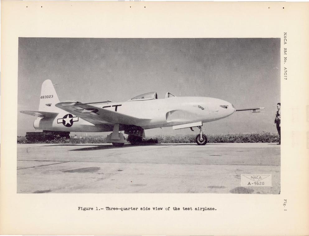
The airplane usnd in the se flight test s was a t urb0-.1et-propellod f ighte r . F igur es 1 and 2 c.r e photogr-aphs of tho air :pl a ne as instru:-mentod. for fl ight . thr'Je- ·vkw d.r:J.wing showing tho 6:(lamri (.,~~
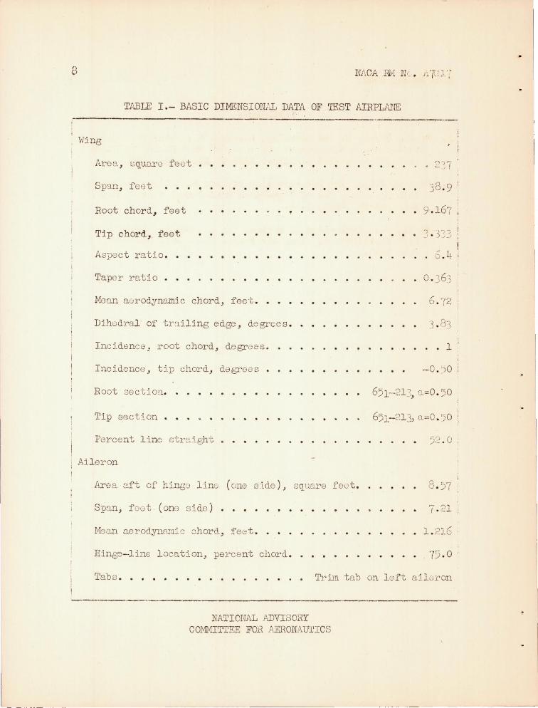
l ocations of ,·ring pressure orifices is pr0 3ente ci in fi gl)TE., ':. . The basic ciirnensions of the airpl a ne arc present~7d in tabl e I. '1'h0 geome tric .tvrist of the wing is shown in figl.lre 1+.
Standard HAC;' photogra phically rocordj,'ng inst J:l1J!l0n t .J wore used t o record tho wing orifice pressures a nd otho!' qu,qn·':.i t::.os durinG flight . A more complete description of tho instrulnGntc.t:l.on :.nd ·3,ccuracy of the e xperime ntal dat:>. llJ£l.~ be f ound in r of e r e nce 1.
RESULTS l'..ND'DISCTJSSION
The pl~imary comparlson made i n thi ~ re'port is bet"lGDn the f.1c'1su!..~ ".., (1.
" ,

4 NACA TIM No . A"!GJ.7
distribut i on a nd the calcul ate d distribut ion obtained using the method of refere:q.ce 2. The se calculation s are based. on a general ized method of applying l i ftin - line theory, using a series of succeF:sj.ve approximations ; that is, f rom t!1e funriamentql riowmlash e qua t ions , a spanwise distribution of dowmrash anglo is f ound for some i n:i.tl':1.1 assumed l oading a nd, from the difference betwee n the eometr :l c and. com})uted downwash angles at each station of the span, tho e ffective angles of attack are determined . \-Jhen the effective a.ngles of a tta ck are appl ied to each section lift curve , lift coefficients at each station are obt aine d wh ich, vrhen mul tipl i e d by the r a t iO of the chord. at the station to t he mean chord, . define a ne w. check di stribu-· tion. As a second approximation, a n assumed spnn loa.d.in,,· is t ,: }:,'; n between t ho first approximat ion and the che ck points . '1'he :fr08es3 is continue d until the check loadin g coincides vri th that from which it "as derived .
To enabl e the comparison to. be made on tho basis of equ2.1 ",1n(5-penol normal-force coeffici ents, it was ne cessary to compute: the wing-pane l normal-force c oe fficie nt vo.ria tion wi t h airpla ne anG10 of a tt8.ck . Those calculations were made by tho me thod . . of r e f or cmce 2 , using the t wo-dime nsional section M.ta obtai-ned on thE) NACA 651-213 (a =0 . 5 ) aj.rfoil in t he Ames 1- by 3-1/2-foot h igh-sruccl '''ind t unne l. (See fi g . 5 . ) Tho cal cul a t ed variat ion of ,.rin (:;- ·pano l normal-forco coeffici e nt ,·,i th a:i.rpl a ne angl e of att ack .'3,1'0 pr0sontod in figure 6 .
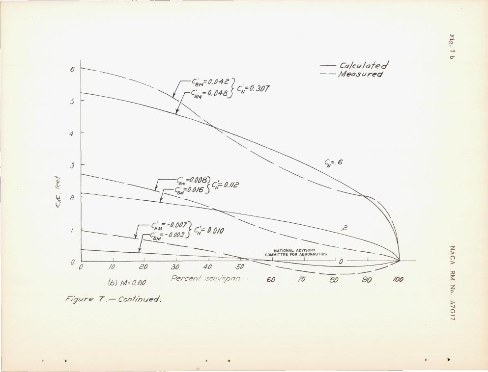
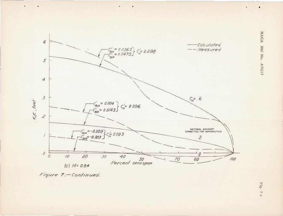
The r esul ts pre s.:mted in fi f,'UTe 7 shO\f the comparison botwe ·n measured a nd calcula t ed span load d.istribution for sove r nl valu83 of Mach number <.'.nd airpl ane nor:tlk'1.1-force coofficie nts .. In comp~ring the chordwise l oadj.ng CnO at each individual spa nwise· station, considerabl e varia tion bs tween the calculntod, a nd mee-suyod loadinG will be noted at Mach numbers ab ove 0 . 60 .
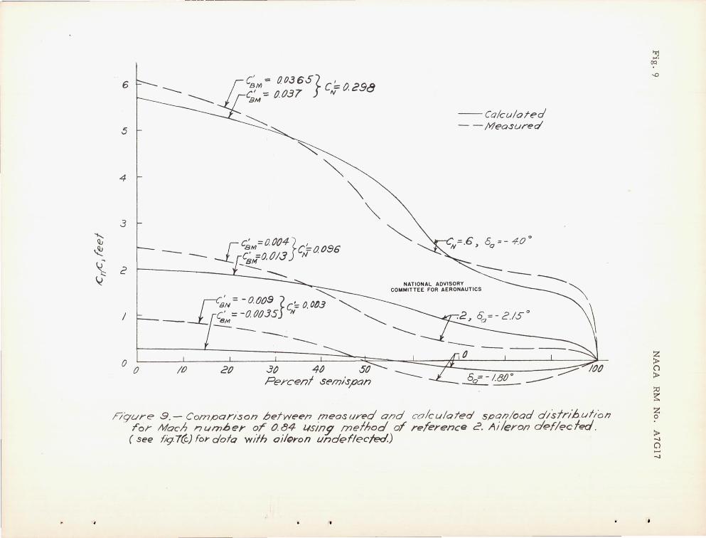
An earl ier report (re f er e nce 1) on this sc.m.e i nstallc.tion attri buted a portion of the inboard shift in the spamiise loao. di s tribution measlITed in flight .to the upfloating ail eron which o clrrrod in flight a t the higher Mach numbers . For the calculated distribution sho,.,rn in figure 7, no consider~tion we.s raade f or the effect of · an upfloating a ile ron. Extrapolating the section d.ata ohOim in :LGUre 5, for M = 0 . 84 , to the u iloron a ngl es t :tke n from r efer ence 1 ( shovm in fig . 8 ) the span l oad distr::'bution prt')sontc(l in figure 9 was compute d a nd compared .rith flight r esul t s .
Furthe r comparison of the sectiona l 10::J,ding vlaS obt a ine d by computing the wing- panel b(mding-momcnt coefficie nt based on the bending moment about the 25-percent semispan station . To e nabL
NACA RM No . A7Gi7 s
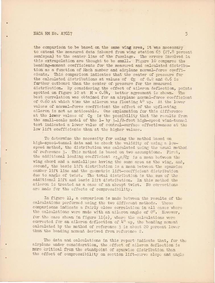
the comparison to be base d . on the same wi ng a rea, it ' ''as necessary t o extend the measured data inboard f rom 'fin station 65 (27 .8 percen.t semispan) to the center line of the fuse l age . 'I'he err ors i nvolved. in this extrapol ation are thought to be small. F5.E,ure 10 compares the bendi ng- moment coeffic ients for tp.e measured and cal ulated dictrib1~~t ion a s a function of Mac h number a nd a irplane n ormal-for ce c<?eff5.cients.. Thi s comparison indicate s that the center of pressure for the calcul ate d Mstribution s at values of CN of 0 . 2 a nd 0 . 6 is farther outboard than the center of . pressure for the measured dist ribution . By conside :dng , the e ffect of ail eron d.eflectj.on .. po~.nt8
spotted on figure 1 0 at 1>1 == 0.84; battEJr agreement is shown . '1'he best corr e l ation 'vas obtained for a n airpl ane n ormal- force coeffici0nt of 0 .60 at which t:Lme the a ileron "Tas f l oatin t 40 up . At the 1 mv0 l '
val ues of norwBl-force coefficien t the effect of the upfl o t7ng ai l eron is n ot as noticeabl e . One explana t ion for thi s differenco at the lowe r val ues of CN is' the pOGsibility tha t t he r OGults from the small-scal e mode l of the 1- by 3- l/2 ... foot high- spee d vrind.-hmnel t est indicat ed a l ower val ue of control-surfac8 eff e ctivenoss at the l ow lift coefficients t han at the h igher valuos .
To doter mine the nece s sity f or using the me thod. based on high-speed- tunne l data a nd to check the validity of usj n~ e. 1 0\-1-
speed method, the distributi on 'vas calcul ated usin e; tha us);,3ol method of rE;forence 3. This method j.s based on t,.,ro assumpt ion s . Fir :::. t , the additional l oading cOE;ffi ciGnt Gl aC/eN is a moan botween the wing chord a nd a semiell:lpse havinG the sarne area as the wing, ana. , "econd, the basic lj f t distr ibution is a mean ba b-leun the spaml::!.se camber l ift l ine a nd the geometric lift-coofficient distribut:i.on due to angl e of tvist . The total distri ut jon js tho sU-'tU of the additional l Ut and basic l ift distribution . In t his method the aileron is treat8d. as a case of an abrupt tvTj.st . No C01'r9c t Jon s are made for the effects of comprussibility .
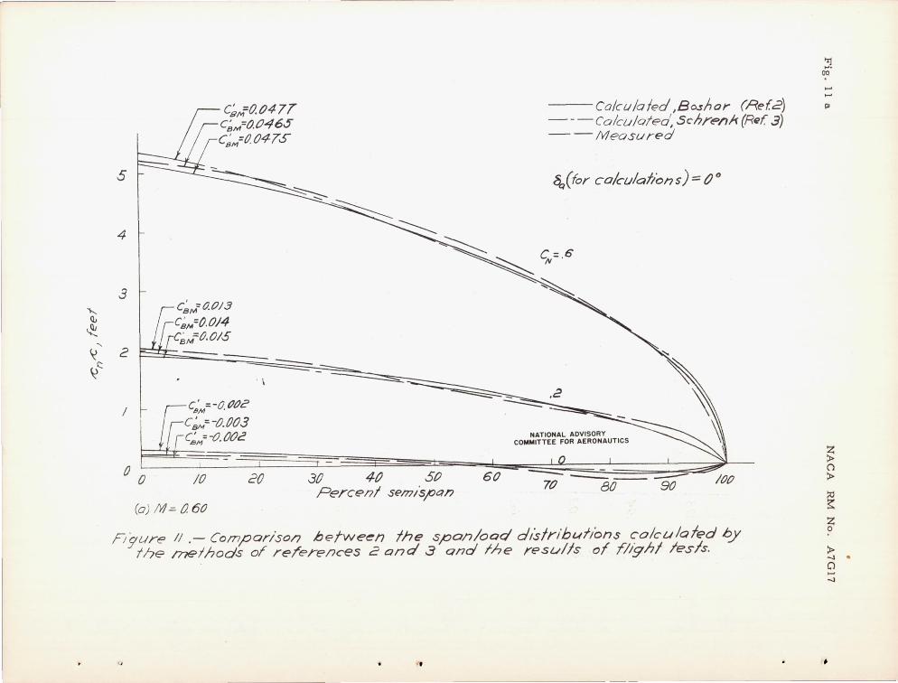
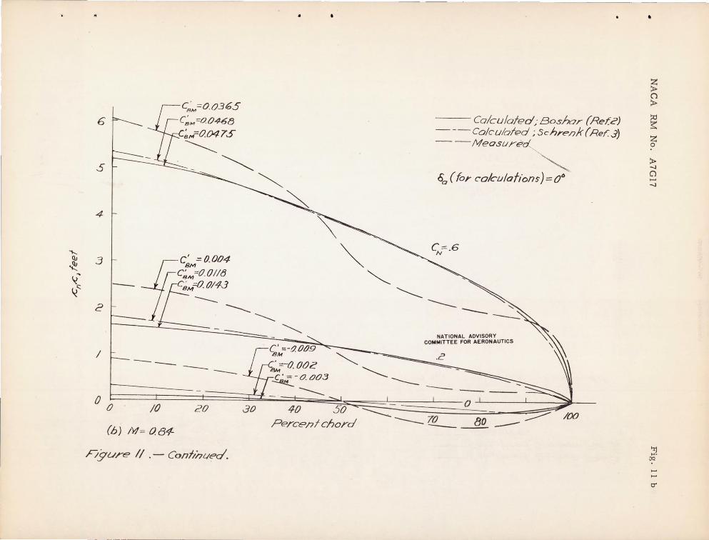
In fj.gurc 11, a comparison is made bctlleen the results of the cal culation s performed using tho tvo diffenmt methoo.s . 1'b080 comparisons i ndicate a fair l y c l ose correlation i n a ll cases whore the calculo.ti ons were made with a n ai l eron RnBle of 00 . HOvTeV:8r , for tho case shovm i n figure 11 (c), ",hor'.-: the cal cul ations were corr ected for a n ail e ron de flection of 4° up, tho bending mom:mt cal cul a t ed by the method of reference 3 is a'hout 20 percent l ov})]. ' than t he bending moment derived from r e f e r once 2 .
The data and cal culation s i n this r e port· indicate that , for tho a irpla.ne under consj.deration, the effect. of aileron deflection is more critical from the standpoint of spanwi88 dlstribution than the e ffe ct of comprossibi l ity on section lift - curve s l ope; a nd [1n{310

. '.'~ I
6 NACA :81'.1 lTc.,. A'{Gl'7
of zero l ift • . In thi s part icular case ,.,rith the a iler on de f l ec t ed. uP .. the re is a n ~nboard shift in ·the l oal thus causj ng a do cr aase in the be nding moment; a nd it is apparen t the.t ne glect of the affect of ailC:i ron upfl oat ·in design calcul ations of l oading would be consorvative . I t is conceivabl e .. howeve r .. thr:.t in some cas() s wtng a nd ai l oron characteristics mjght be such 13 S to cause a dowmvard defl r.;; c-·· tion of the a i l oron at htgh Me.ch numbers , t hus producinf.!, Lsr6nt cll·· bondin moments. It is recommendod , thorof oro , that cal cul a tions of 8p~nwi se 10a~inG at the higher ~bch numbers incl ude concide r a tion of th3 offect of a ileron defloction. In thi s r e ga rd it is appe.ront that research is nece ssary to provide me thoQs for Gstirnatin,s; [lJ.l c"ron de f l e ctions at highor Mach numbers .
CONCLu~ING REMARKS
Ove::o t he M:lch number range for whi ch t e sts we r e made , it was shown in thi s part:i.cula r case tr.2.t cons·i.dera bl e vLrta ti.on occurred be twGG n the se ction norl1l2..1-forco cOGfficie nt Cn .as r.lo2.surod:md. OB
ca l culate d ,.,rhore no dof l 0ct ion was con8ider8d . This d8monst:r.[~t0 ~.
th t 3 nocess i t y of c onsidering the aile on an810 at hi r.rh Mach nWl1b() rs t o obtain a corre l a tion be hreen· mea surod and ca l cu13:bd 0_i s tr:;bu-· tiona . In thi s C8.se be tte r corre lat ~.on ,,'as obtaJ.ne d ooi:-"70on m03.ouruc, and ca l culatod val ue s of span loa d dt(3tr ibutton :~t hjEhol' D. ir1l1a nu normal- force cooffici ;.mte tha n at lowe r airvlahe norm·:'.l - forcc cO'3 fftcie nts . Comparison of TIlOc.surc d and c2.1Cnlatod v~ lue s of span l oad distr ibution shO\.,red that t he upfloatj.n n a::. l e ron h:ld il great e r (; ffoct on the span 102.0. clist:dbut1on t han chanGG s in li1't- curve s l ope a nd anGl e of zero l ift duo to comprcssibillty . I t is r ecommende d thc.t ca l culclt io:1 of spa nwi se 10adin3 2t high Much numc8rs i ncludo tho e ifoct of a i l e ron deflectiona ~
The dtffe renco ootwcon tho ca lcul a t od distribution::: , ewing e i ther r e f e r onc8 2 or 3, a nd tho me2.ourod ·· dist:cJqution indj cnt od by tho 38 r o suI t s a r e: ,.,ri thin t ho:) a ccura cy of the pro lim:i.na ry <io s i gn conoidc r a tions . Honco , in thi s particulQr · caGe th.) s impl e mothod (r of e renc" 3 ) gave a s good a n c.greornont 1-lith t est r0sults s . r of -.) r enco 2 but tnvolve d approximate l y one- thj r d the tirlG :-.:.nd did not r e quire additiona l te sts to ootaj.n aJ rfoil--scction d.c.ta .
Amos AcronautiC2.l I"aoora tory , Na tional Advisor:{ Committ3e for AcrOl1:1utics J
Moffe tt Fiol d , Calif .
I.ACA RM No . A7G17
. . '. REFERENCES
1. Brown, Harvey H. o.nd Cl o1.'.sing, Lo:vrrenc0 A. : Wing PrG;:,:sUTf3-
Di s tribution MeasUJ:'em nts Up to 0 . 866 Mach Number in Flight on a Je t-Prope'11ed Airpl ane ., NACA TN Ifo. 1181, 1947 .
2 . Bos h:::.r , John: The De termino.tio~ of Spa n Load Distribu '!:' lon a t High Speeds 'by Use of High-Speeu Wind.~Tunne J. Secti on D:::.t c . NACA Ac:R No. t,·B22 , 1 9 l.>4 •.
3. Fla tt , J.: Evaluation, of Methods for Dot e rmining SpE\l1i.risiJ Lift Di s tributj.on . Army Air F o:cces 'r ,)ch . Rell . no . }~·~)52 J June 1943.
8
TABLE I. - BASIC DIMENSIONAL DA1~ OF. TEST AIRPLP~m
\'<ling
Areo. , ~~uare f eet •
Span, f08t
Root chord" feet
Tip chord, fee t
Aspect ratio . •
Taper ratio • •
Meo.n aurodYTh.'Ullic chord, fee t .
Dihodral of tr:liling edge , degr'co s .
Incj.dence , root chord, degrG8s .
Incidence , tip chord, degrees
Root section.
Tip section • •
Percent line ctr:::.ight • •
Ail eron
Area e,ft of hingo ltno (one s :Lde ), s Cluare fec t.
Spun, f oot (one side ) •
b1ean aerodyn£un.ic 8hord, feet . .
Hinge-l ine location, percent chord .
..., OJ,......
• -, I
38 . 9 l
. 9 .167 ,
· 6. 4
. o. J63
· . 1
651- 213,0.=0 . '50 :
52 . 0
7 · 21
. • 1. 216
75.0
Tabs . Trim ta~ on l eft ai l Gron
-------------------------NATIONAL ADVISORY
CO~rrTTEE FOR AERONAV£ICS
4U:1023 t"-
Figure 1.- Three-quarter side view of the teat airplane.
~ ()
:t>
~ ~
Z o
:t> -.J ()
-.J
~ OQ

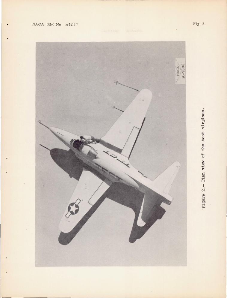
NACA RM No . A7G17 Fig. 2
. «> ~ rl ~ M
..-I cO
+> m «> +> «> :S Ct-t 0
~ ..-I ~
~ I .
C\J
~
9 ~ ..-I ~
L

r
J

NACA RM No. A7G17
A //(?70n ht"n'1e //ne
af 75 % chora.
1~04---- 467
-----
1== 414
•
207
Orifice slcdlons
All d/mensions /n Inches
--.. -.. -------
NATIONAL ADVISORY COMMITTEE FOR AERONAUTICS
~I
Fig . 3
Flgu.re 3. - Three-View dra.w/nJ of the test airp'O-ne.

I I
t, §
th .v, ~ ~o
" Q, ~ . (:: ~ ~ ~ 't)
~
~~ ~ v " t:: W, O ~
-Q " Q., ~ II) ())~ c: .c:: ~~
II __
01-1----
-/
o /0 cO .30 40 50 60 70 Perce/71 semisPQ/7
Figure 4- .- GeomfEOlric Iwisf //7 tile wing of loe lest Qlrplone.
80
NATIONAL ADVISORY COMMITTEE FOR AERONAUTICS
90 /00
. ' ..
'7j .... . DO
ol'-
~ ()
~
~ ~ Z o
~ -..J C)
-..J
•

NACA RM No . A7G17 Fig . 5
- 6
v~ , "' M:..60 c::-. Il, "- .8 . t..
..-:: .80 , .84-~ 0= o· C)
~ a
\l, .86 ~ ~ 6 :< -30
I -I ......... \::l .4' ~ .j ~ ~ / .~
lJ Il,
(f)
0 o· 0
P I - / -
/ NATIONAL ADVISORY COMMITTEE FOR AERONAUTICS
-.4 -; , , I , , ,
-4 -2 0 2 4 6 8 0( For M=.60
Figure 5.- Secftol7 dola on fh e NACA 65.J.-21.] (0 =.5) 0/';-/0// from lesls //7 Ihe ~mes /x ..3j 1001 /-I/gJJ-S;oeed w//;d Tun n el.

Fig. 6 NACA RM No . A7G17
M=.6 _ .8
.84
000
A/rplqae o/7g'/e or ollock, O<Q}deg
86
-4 -2 0 2 4 os, (or M~ .60
NATIONAL AOVISORY COMMITTEE FOR AERONAUTICS
Fi9ure 6 . - Co lculoled Varlo/loll of w/;!(] -panel
normal - force coeffic/eat w/!17 o/r'plane a ngle of
a/lock.

""' Q;
~
6
5
4
3
~2
I
-- Colculated --Measured
=:::::::::::-- r-,C~M = o. tJ4.65} ~ rC~M=OJJ4.75 <=P30
~ ~ ~
c· -r- 81'1-0.013] , F ~C~=OOIS . CN =o.096 --=:::::::::::
c~ - 0. (JOe 7. C;= tJ. 004 "=-0003j 19M .
~~ ~ ~: . 6
NATIONAL ADVISORY COMMITTEE FOR AERONAUTICS
I -I - i~ 0 :::):J o 0 /0 20 .]0 40 50 60 - __ _ _ =--
. 70 80 90 Percent semlspon (0) 1Yf= 0.60
Ft"qLlre T.- ComparIson .be/wee/? measured and colcu/oled sp,a/7 load dislrihu//ol7 Llsing me/hod of reference 2. Aileron undeflecled.
/00
~ ()
~
~ ~ Z o
~ -.J
Cl -.J
'"rJ .... ()Q
-.J
P>
........ QJ
~
~
6
s
4
-3
2
/
o o
-- Calculaled
--- c ' -004CJ ---- -----~ ~M- • c~={) 3()1
- - )v/eosur~c:I
r c =O.tJ48 8M
~
~ ~
---- -- ;-~~_=~tJf)82 C)= ().I/2 ------.t... ,-~M -(U) /6 j
----.::: ~
~~ ~= . 6
~
8M .//// I -----ire I = -d /1/1T]
Q~M= - (J.tJ(J.J ~;;; tJ. Off) " --- .2
---- ----- --NATIONAL ADVISORY -- --- -- COMMITTEE FOR AERONAUTICS
~I /0 20
(b) /Y1= 0.80
30 40 50 ------ 90 70 80 Percen! Sel7ll~;OOn 60
o
~
---Figure T. - COI7/;i7ued.
~
"'1 .... OQ
-.J
cT
~ ()
~
100 ~ z o
~ -.J
C)
-.J
I
"';0.",. III
~
\J~ \.j
6 p----.-... --Cokulole d
5'
4
3
2
I
~ 8/>/ - 0. tJ365 ' rC~M= O'0415} eN= (},298 ~CI-
~
'\ ~
---- C~M = 0.0.04 } C~M= 0., 0143 c~= () 096
----- -- ~ L C' =-000'0; 8M ,v ,
_ r~=-o.a7.3 C;: rJoa3 ~ --
~
- - /Vleasu red
C/y= ,6
,---, -------NATIONAL AOVISORY ~
COMMITTEE FOR AERONAUTICS \ \
,2
------ ~ ~ 1 r ------ -tJ 1 >-.1 --o /0 20 30 40 s ........ 1 0
50 ~TO ~ (c) M= 0,84 Percen! semlspcln--_8~ ---
/0.0
Fi'gure 7.- Conlt'nued.
~ ()
:t>
~ Z o
:t> -.J
o ...... -.J
'"Ij .... '
OQ
-.J
n

Fig. 7 d NACA RM No. A7G17
If> <.J f= =>
>- .. a:z 00 If> a: ~~ "a: ...JO
\ .. u. z", 0",
~~ ->-~t:
~ Z:I
,~ :I 0
~ ~ <.J
~ II)
\ ~ \ ~ ~
~~
I I
J ~ j I
I ~J / Ii / . rt)
V ~ ~
~ ~
\I) Q) ~ ~, ~
/ "'i- ~ ~ , II~ ~ ~ '-.l
/ ~ ~ ~
~~ , " I ~
Sl~ ,,1 t"r) ~~
/ I:::)~
~ Q
" " ~ ~ "< So, I ~
~q)~QJ I ~'S \() Q c:::s • ~ <Q ,~ ~
~ II I: I;:::i l.J ~ ~ 1\ ~
, OJ' CQ ~ C)
\..)
I ~ ~ I '-
t-....
Q., , ----1--_ <;:::, ~
fY) <\J "- ~ .0-,
faa) r :;I'.::v ~

NACA RM No. A7G17
4
()
.60
NATIONAL AOVISORY COMMITTEE FOR AERONAUTICS
.65 .70 .75
Mach numher 1M
.BO
Figure 8.- Varia/iol7 o f olleron angle wtlh Mach numher tor the fes f a;"rp lane .
.85
Fig . 8
~ .6
..,..... Q;
~ ~' <...t.r:::.
6
.5
4
3
2
/
o 0
- -
~M = (J().365} c' _ C!.-8M - 0.037 N- 0.298
I C~M = 0. 0(J4} , ~rc;M=O.()/3 CtJ=o.{)S6
"---'--- --r~N= -O.(}(}$} ~ _ -LrC;;M = -0. 003S c,.,'= O. OIJ3 ~ - --- ~
It} 2tJ ---
30 4~ S() Per-cenl sem/span
--CQ/cu/oted - -Measured
~
-----~ ~~ NATIONAL ADVISORY COMMITTEE FOR AERONAUTICS
, ~
04= -~ ___ ::::::----
Figure 9.- Comparison between measured and colcu/ated span/ood disfn'hult'ol7 ror Mach nl.lmDer oT O. t34 l/$j179 mefhod of reference 2. Ai/eron dt!?flecfed. (see rjq1(c) for dolo wdh oi/f?ron undef/eckd.)
':tj .... . OQ
-.D
z ~ ()
~
::u ~ z o
~ -.,J
Cl ..... -.,J

NACA RM No . A7G17
.05 C=.6 N
" .04
.03
.02
C,.,,=.2
.01
o r
C ={) N
-.OJ
-:02
- --------
--- -----
Fig. 10
--------- ""'~Sa :=O - 4.tJ 0
-- Ca!culoled ( oa: O) - - Meas ured
<:) Calculations made wllh ol/eroo floallng ~
~6a= -2. /5 ° 0
"" " '"
NATIONAL ADV ISORY COMMITTEE FO R AERONAUTICS
.6 .7 .8 .9 Mach n~m.h@r , M
Figure Ie? . - Varia/ion of W,1/79-,P0n,@/ b endl/7g -moment coe//l c/eof O!;ou/ t s e~71.spal7 w;/h Mach numher for th e meas4red /ood//7S' and the loading co/cuJoled by m e/hod cf reference 2.
"'Qo
~ .....
5
4
3
C:sM=o.04 7 T c~M=o.(}4 6.5' C~M=(J.04-TS
C~t.;:: (J.tJI3 c~M=()'OI4 C~M=O,O/5
Ca/cu /o led ,Bo.shol'" (Ae{.2) ---Ca/culolea: Schrel'lA (R~[ 3) --Meosured
<\( for calculafion s) ~ ~ 0
- ==---~ ,2 -~r
I
--==--2:--:::-::::::~~ ~ _ .E
' \ ~'..:::,=~,:;;;; C' =-OPtJ2 8M .
C~= -O. ()03 C~M= -o·OOC NATIONAL ADVISORY
COMMITTEE FOR AERONAUTICS
() 0 /0 20 3fJ 4tJ 50 60 80 -- ~. ::::.:.---90 Percenl sem/s,PCln
(0 ) M=- () 60
100
Fi"ytLlre II .- Comparison hetwe~n the span/oad d/slribuf/ons colculal€>d hy the /?7e lhods or reTere17ces .2 and.3 and Ihe resulls of r/ighl lesls,
' f
"1 .... OQ
..
... PI
~ ()
~
~ z o
~ -.I •
Cl ... -.I
'1-.. (lJ
~ \,(--
~'
6
5
4
3
-2
/ --
C; M=o.0365
C~M=0046t3 ~,.,=o. 04 T S
~ ~
c' = 0.004 8M
C~A1=(J.O//8 C~M:::(J. 0143 --
•
~ ~
----............ ~
=:::::::::::::: - - ~ C' =-(}' 009 BM
'=.-0002 dM . -C' = - 0 . 003 --- ~-----------
Calculated .. ' Bashor (Ret:L?) ---Co/cu/atl?d; Schrenk (Rer.d) --Measured..
',~
00
( for c-olculafions) == 0°
~--- ----~ o l /0 20 j; I ;0 '5'0 • ~ ~ 0 I :;:::;;>,
Perce/7tchord ---- - --.!l2.. ---(/;) !'Y/= 0. 84-
Figure II . - Conli/7t.1ed.
•
~ (J
~
~ ~ z o
~ -.J
o ...... -..J
~ ..... JQ
......
...... 0'

r ~
I
I
........ <U ~ ,
6
5
4
.]
" 2 ~t
/
o 0 /0
(c) M = o.e4
2 0
Fij;l'ure 11.- Conc/vd@d
30
~ ~~'
'"
--- eolculaled; Bashor (Ref. 2) - - - Co/cu/o/f>ctSchren/( (Ref..3) - -Meosured
C~M=o.0365
C~",,=(}.029S C~M -=0. ()37
°0 (for colcl.llaftons) = -4:r?
........ C=.b
\~~--~~ '\~i
NATIONAL ADVISORY COMMITTEE FOR AERONAUTICS
4tJ Sf} 60 TO t30 .5V /00 Perc@nf sel77/spol7
"Ij ..... OQ
n
~ ()
~
~ ~ Z o
~ -.J
o -.J