naca - digital library/67531/metadc62380/m2/1/high... · national advisory committee for...
TRANSCRIPT
4?y fn / 2; < d&d 77 copy +a FM SLW
,
NACA
RESEARCH MEMORANDUM for the
? Bureau of Aeronautics, Department of the Navy
4 .5 , AERODXHti~~IC Cm ISTICS AT MACE NI.NERS OF 1.61
f
$ I-’ 1, r: ‘Cl
g
‘F )
#$ \ ‘ :
: ’ ” 1 : 1 I
,
I
1
t
*. ,$
[>
I
i
> I I AND 2.01. OF VARIOtrS TIP COUTROLS OPT THE WING PAn'EL OF 1 I r 1 &iLOWAIS KODBL OF A MRTJX X%344-7 (BULWUP) MISSILE I 1
;i
\ fr :-‘r’
\ c ,.: , -‘- .z , 4.L. 2, I f--J i'
i” I , \ r* :i. I I,+ . ( -'. .-':
%sv NO. ~ACA AD 3106
By Cornelius Drfver ; .+ 4 .,’ I’ 1 4
/--a ,::) ..I' Lmgley Aeronautical Laboratury , 'r 1 1, .--1 /.. Langley Field, Va. c 1 "f-l
t 1 i .,l 1 > -* CLASSWED D”CUZ.:EiT _I .
I h.
-. L SF Thi; d::um~nl conhir~~ eb,3fied icdorm~tlo:~ ‘dfcctm ," tt,? i!+liCti DEfCnre Of the Ulule3 SL?ter. 7.Wh tt:
I n.e-aIn: of ti-,I Eqml;'C Act, WC Is:723 ?Li 70:. It; tr-uL;mEsion or tto ravelltim Of its contanta in q.
,, t In’uiu’ r tc, m uelutb,n,.~ *? i 5 x-con is prO:iib*t*: 3 by lx:.
‘2 1
% 1
rL I I
~%h4 . i NATjONAL ADVISORY COMMITTEE FOR AERONAUTICS
: -.- 1 2 -.
_ ..-... -- . . i _- -. -. _ ---_ _---. ,.-.. _ ,.-- __ ,,~.
-._. -,--..-*-^ _-- _(..i_---_ ._

NACA m ~~56~20 ,- _- : -r ;I
NATIONAL ADVISORY COMMITTEE FOR AERONAUTICS ‘;: '...
RESEARCHMEMCRANDUM , .*
for the
Bureau of.Aeronautics, Department of the Navy '\
k I _. '-,
AERODYNAMIC CHARACTERISTICS AT MACH N&BERS OF 1.61 $h 1 AND 2.01 OF VARIOUS TIP CONTROLS ON THE WING PANEL OF +$' .-F ID
A 0.05-SCALE MODEL OF A MARTIN XASM-N-7 (BULLPUP) MISSILE if+.
TFD NO. NACA AD 3106
By Cornelius Driver
-.
--
* ,_ ; . . .
,,-
:
: ,p.
.e-
^, .M ’ ,
” -’ .I-
: ‘0’ ‘. ~ I ,..- ;r,.. i’. - ,...’
An investigation has been conducted in the Langley 4- by b-foot supersonic pressure tunnel to determine the control effectiveness and hinge-moment characteristicslof the Martin XASM-N-7 (Bullpup) missile. A half-scale wing panel was tested with a tip control having three different hinge-line locations. The tests were made over an angle-of- attack range from -10' to 10' and a control-deflection range of -15' to 3O. The present paper is a data presentation of the results obtained at Mach numbers of 1.61 and 2.01.
INTRODUCTION d
At the request of the Bureau of Aeronautics, Department of the Navy, an investigation has been conducted in the Langley 4- by b-foot super- sonic presslure tunnel to det,ermine the control effectiveness and hinge- moment characteristics of the Martin XASM-N-7 (Bullpupr) missile. The missile uses a system of gyro-activated ailerons (rollerons) to inhibit the rate of roll. Simulated rollerons were tested on a half-scale delta- _ wing panel in the presence of a dummy body. The rollerons were tested with a simulated nonrotating gyro wheel both on and off. Three different
_.M.
‘..J ..*
i’. I .
. ,.
‘. ” v..
b$:!‘- i ,- .- : ‘, /
; _‘ ; ,‘“. \ . . . . . ..” ~,
-

2 IUCA RM ~~56~20
balance-to-control ratios were obtained by means of varying the hinge-line location of the control. This paper is a data presentation of the results obtained at Mach numbers of 1.61 and 2.01.
SYMBOLS
The data are referred to the stability axis system (fig. 1) with the center of moments at 3'7.2 percent of the exposed wing root chord.
S wing area (total = 90.01 sq in.)
c' wing mean aerodynamic chord (10.7% in.)
Ma moment area of control surface aft of hinge line
M Mach number
9
a
6a
L
D
M'
dynamic pressure
angle of attack, deg
control deflection relative to wing (positive trailing edge down on right wing panel), deg
force along the Z-axis
force along the X-axis
moment about the Y-axis
Mx
Mh
CL
CD
cm
moment about the X-axis
moment about the control hinge line
lift coefficient, -$
drag coefficient, $ M'
pitching-moment coefficient, - qsc
ch
Mx rolling-moment coefficient, - G-b
Mh hinge-moment coefficient, - 2qMa
/,
NACA RM ~~56~20 51 *
TEST CONDITIONS AND PROCEDURES
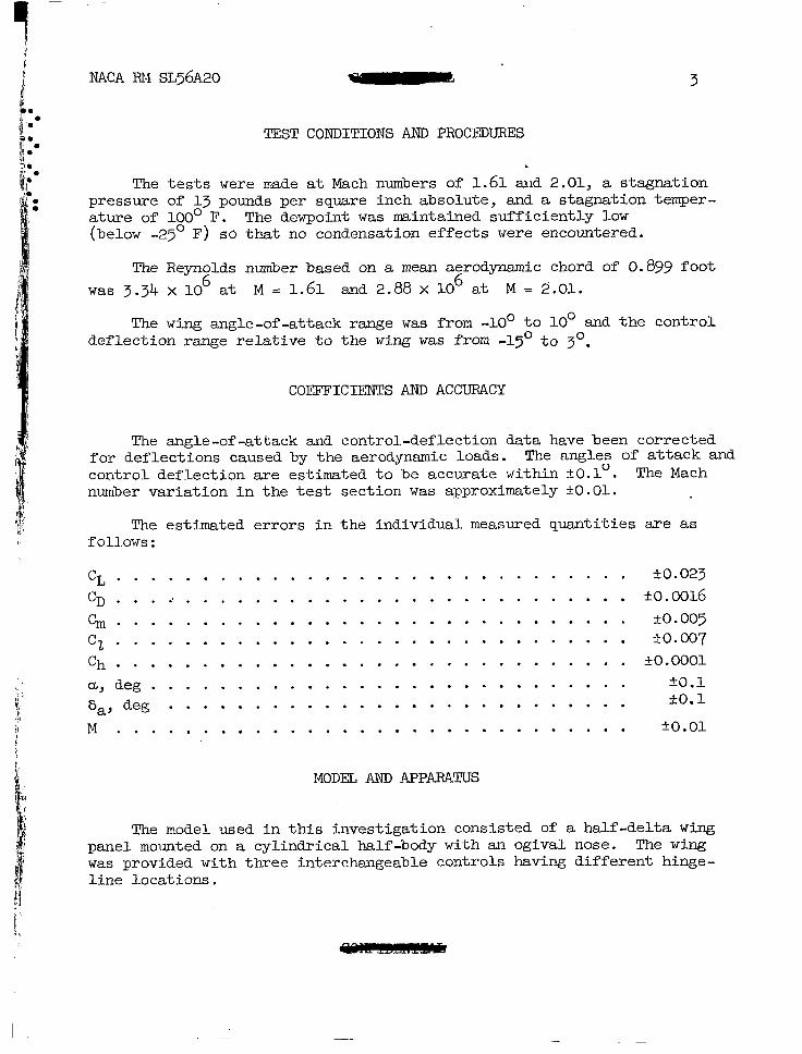
The tests were made at Mach numbers of 1.61 and 2.01, a stagnation pressure of 13 pounds per square inch absolute, and a stagnation temper- ature of 100° F. The dewpoint was maintained sufficiently low (below -25' F) so that no condensation effects were encountered.
The Reynolds number based on a mean aerodynamic chord of 0.899 foot was 3.34 x 10~ at M = 1.61 and 2.88 x 10⁶ at M = 2.01.
The wing angle-of-attack range was from -loo to 10' and the control deflection range relative to the wing was from -1~~ to 3O.
COEFFICIENTS AJJD ACCURACY
The angle-of-attack and control-deflection data have been corrected for deflections caused by the aerodynsmic loads. The angles of attack and control deflection are estimated to be accurate within +O.l". The Mach number variation in the test section was approximately kO.01.
The estimated errors in the individual measured quantities are as follows:
CL. . . . . . . . . . . ..'................ -1-0.023 CD... i.......................... -~0.0016 cm.............................. -to.005 cz.............................. *o.c07 ch . . . . . . . . . . . . . . . . . . . . . . . . . . . . . . _+0.0001 a,deg............................ +0.1 6 ,,deg . . . . . . . . . . . . . . . . . . . . . . . . . . . kO.1
M . . . . . . . . . . . . . . . . . . . . . . . . . . . . . . io.01
MODEL AND APPARATUS
The model used in this investigation consisted of a half-delta wing panel mounted on a cylindrical half-body with an ogival nose. The wing was provided with three interchangeable controls having different hinge- line locations.

11,; ; ~ 5 i ) F bj z
. . = 0 . I . . f:.’ hi.. . .
. . .
4 NACA RM ~~56~20
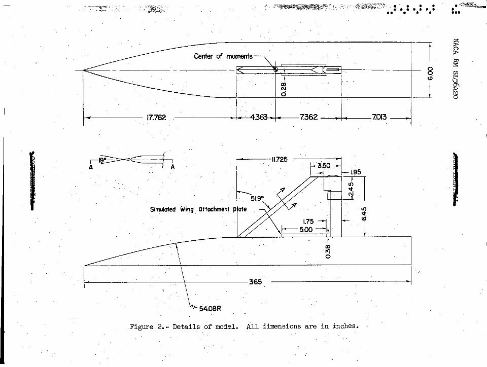
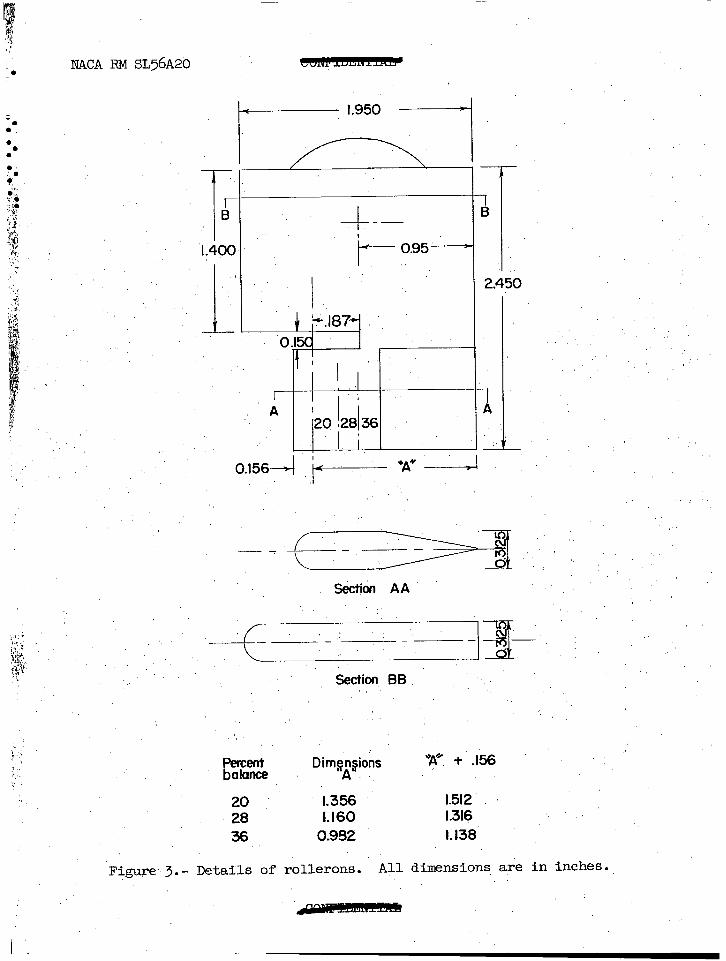
A drawing of the model is shown in figure 2. A wing mounting bracket, simulating the attachment plate used on the full-scale missile, was mounted on each surface of the wing as shown in figure 2 for most of the tests. Forces measured on the wing included the forces on the wing attachment plate. The rolleron and flap arrangement showing the various hinge-line locations is shown in figure 3. The geometric characteristics of %he model are presented in table I.
The model was tested on a boundary-layer bypass plate as shown in figure 4. The forces and moments on the wing were measured through the use of a four-component strain-gage balance mounted in the turntable of the bypass plate. No forces or moments were measured on the body which was rigidly attached to the turntable. The angle of attack was changed by rotating the turntable, which was motor driven from outside the tunnel.
The hinge moments on the control were determined by means of a strain-gage system which measured the torque exerted at the control hinge line. The angle of attack and the control deflections were set by means of an electrical control position indicator.
PRESENTATION OF RESULTS
The basic results are computed for a stability axis system and are presented as functions of angle of attack a and control deflection 6.
The figures are presented in the following manner:
Variation of basic coefficients with control deflection for 20-percent balance . . . . . . . . . . . . . . .
Variation of basic coefficie;tL ;ith control deflection for 28-percent balance . .
Variation of basic coefficrents ;i~h'c&&-~l'd~fie~t;o~ . . . .
for 36-percent balance . . . . . . . . . . . . . . Variation of basic coefficie:ts ~iCh"control deflection
for 20-percent balance with simulated wing-attachment plate............................
Variation of hinge-moment coefficient with angle of attack for 20-percent balance . . . . . . . . . . . . . . . .
Vsriation of hinge-moment coefficient with angle of attack for 28-percent balance . . . . . . . . . . . . . . . .
Variation of hinge-moment coefficient with angle of attack for 36-percent balance . . . . . . . . . . . . . . . .
Figure
8
9
I.0
11
-

NACA RM ~~56~2x1 5
. . LO . L .
. . ;i ‘L ;.
b *
/ 1
‘! ) i
Variation of wing lift, drag, and pitching-moment characteristics with angle of attack (6 = 0) . . . . . . . .
Effect of the wing attachment plate on the variation of the hinge-moment coefficient with angle of attack . for 20-percent baiance (M = 1.61) . . . . . . . . . . . . .
12
13
DISCUSSION
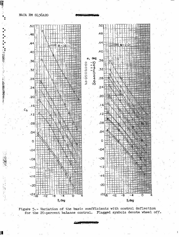
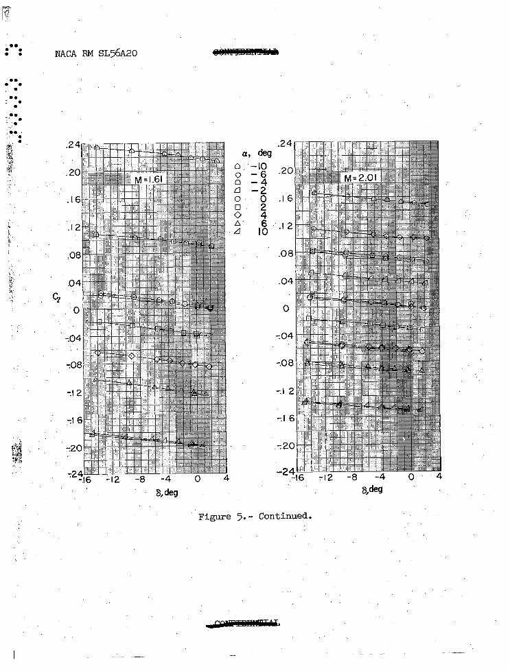
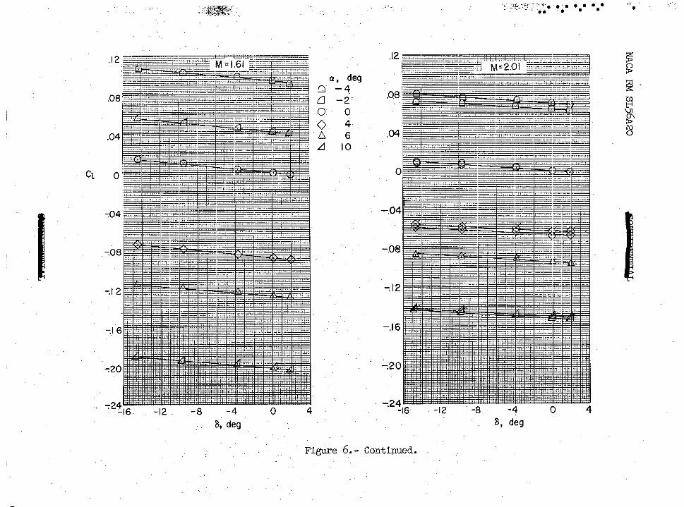
The variation of the hingeaoment coefficient with rolleron deflec- tion at constant angles of attack (figs. 5, 6, and 7) becomes increasingly nonlinear as the control balance increases from 20 to 36 percent. The variation of the rolling-moment coefficient with rolleron deflection (figs. 5, 6, and 7) is essentially linear and indicates constant rolling effectiveness over the angle-of-attack range.
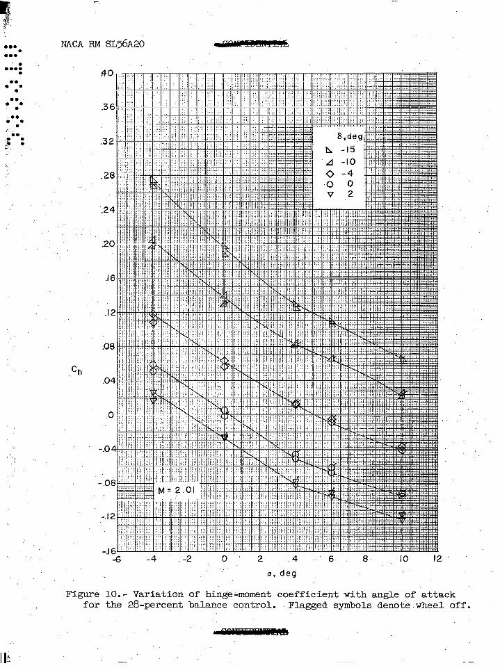
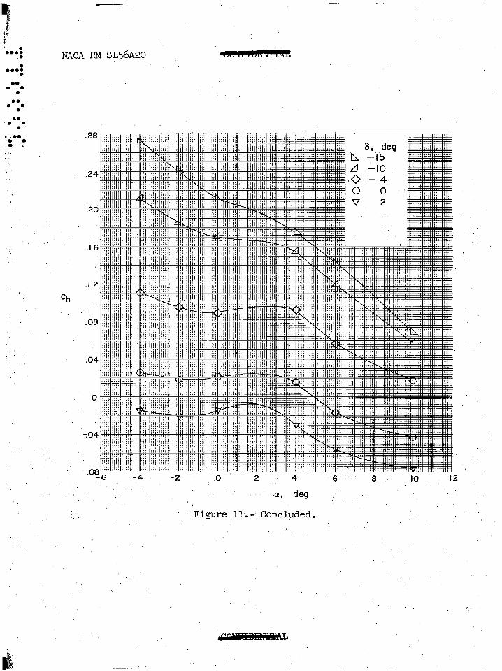
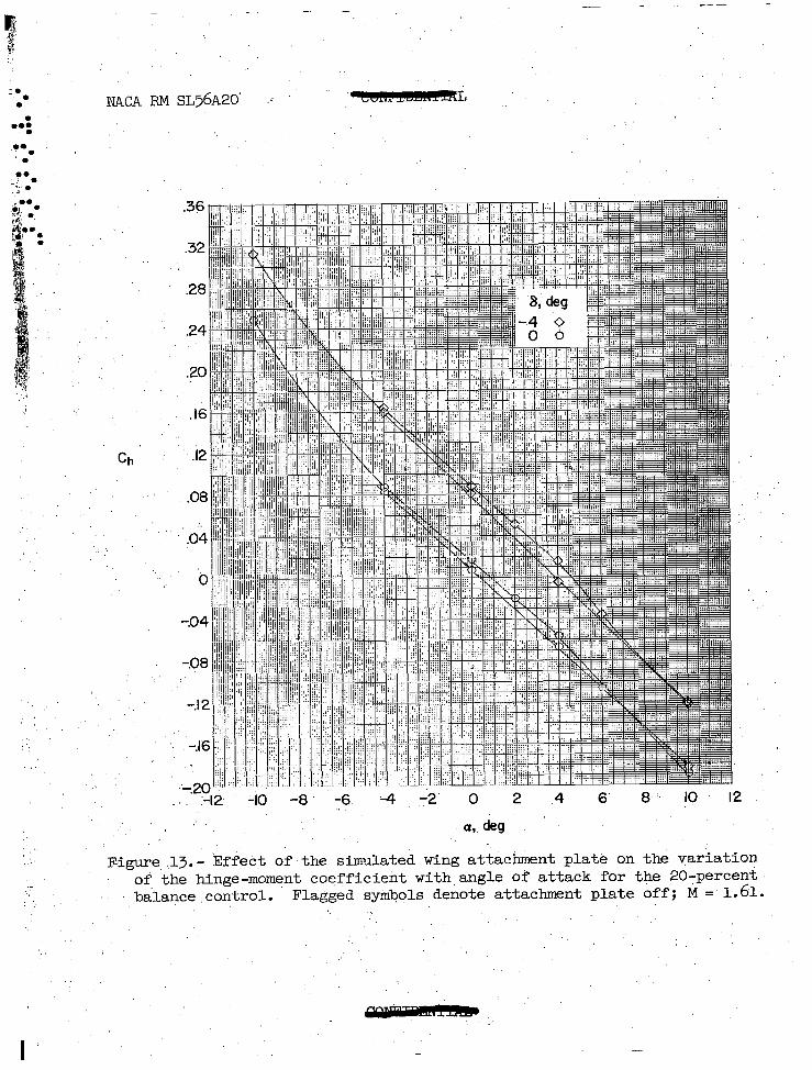
The variation of the rolleron hinge-moment coefficient with angle of attack (figs. 9, 10, and 11) indicates an abrupt change in slope at -Lb0 angle of attack which is probably a result of the shock wave disturbance from the simulated wing attachment plate. The data of figures 9, 10, and 11 indicate that Cb becomes increasingly nonlinear with increasing
control balance. Some improvement in the linearity of Cha may be
expected, however, with the removal of tJ,e wing attachment plate (fig. 13).
Attempts to correlate the hinge-m,ment slope parameters chs and ". Cb with the correlations presented in reference 1 for a family of tip controls were unsuccessful. The poor agreement probably resulted because of the differences in geometry between the controls tested. The present controls had the balance area shielded by the wing ahead of the control and had the wing tip cut off parallel to the stream. It appears that in using the correlation of reference 1 for predicting control hinge-moment characteristics that care must be taken that the control not only belongs to the same family of controls but is also similar in geometry.
Calculated values of C % (refs. 2 and 3) and Cb (refs. 4 and 5) using the linear-theory method also showed poor agreement with the experimental results. In contrast to the theoretical predictions shown in reference 6, linear theory consistently underestimated the experi- mental hinge-moment slopes for the present tests. It should be pointed
II II
6 NACA RM ~~56~20
L . . . . . out, however, that the data from the present investigation correlate well = . . i. . with the experimental. data obtained on a smaller scale model of a similar ! l
b.- configuration (ref. 7).
I’ l
g:
k
I $ Langley Aeronautical Laboratory, ( -'.! 1 1 National Advisory Committee for Aeronautics,
-r Langley Field, Va., January 6, 1956. iv
lhJh&dm .?$ Cornelius Driver
Approved: &-
Aeronautical Research Scientist ., r John V. Becker bi Chief of Compressibility Research Division
mfd
REFERENCES
1. Lord, Douglas R., and Czarnecki, K. R.: Aerodynamic Characteristics of Several Tip Controls on a 60' Delta Wing at a Mach Number of 1.61. NACA RM L54E25, 1954.
2. Coale, Charles W.: Supersonic Characteristics of Rectangular Horn Balanced Ailerons. Rep. No. ~~-13718, Douglas Aircraft Co., Inc., Mar. 31, 1950.
3. Lagerstrom, P. A., and Graham, Martha E.: Linearized Theory of Super- sonic Control Surfaces. Jour. Aero. Sci., vol. 16, No. 1, Jan. 1949, PP. 31-34.
4. Harmon, Sidney M., and Jeffreys, Isabella: Theoretical Lift and Damping in Roll of Thin Wings With Arbitrary Sweep and Taper at Supersonic Speeds - Supersonic Leading and Trailing Edges. NACA TN 2114, 1950.
5. Martin, John C., Margolis, Kenneth, and Jeffreys, Isabella: Calculation of Lift and Pitching Moments Due to Angle of Attack and Steady Pitching Velocity at Supersonic Speeds for Thin Sweptback Tapered Wings With Streamwise Tips and Supersonic Leading and Trailing Edges. NACA TN 26% 1952.
6. Czarnecki, K. R., and Lord, Douglas R.: for Several Tip Controls on a 60'
Hinge-Moment Characteristics Sweptback Delta Wing at Mach
Number 1.61. NACA RM ~52~28, 1953.
7. Anon.: The XASM-N-7 Guided Missile Weapon System - Analysis of Test Results, 50 Per Cent Rolleron Wing Panel. ER No. 6449 (Contract No. NOas54-633-c), The Glenn L. Martin Co., Feb. 15, 1955.
NACA ~4 SL 56~20
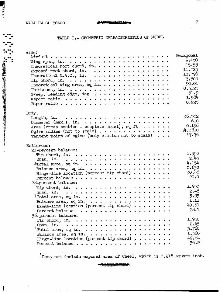
TABLJZ I.- GEOMETRIC CHARACTERISTICS OF MODEL
Wing: Airfoil ......................... Wing span, in. ..................... Theoretical root chord, in. ............... Exposed root chord, in. ................ TheoreticalM.A.C., in. ................ Tip chord, in. ...................... Theoretical wing area, sq in. .............. Thickness, in. ..................... Sweep, leading edge, deg ................ Aspect ratio ...................... Taperratio .......................
Body: Length.in. . . Diameter (max.j, in.
. ..................
Area (cross section - ~o&&-L'kdLj ............. Ogive radius (not to scale)
;s; it . .... .. .
Tangent point of ogive (body station not to scale) ..........
Rollerons: 20-percent balance:
Tip chord, in. .................... Span.in. ......................
Lpotal area, sq in. .................. Balance area, sq in. ................. Hinge-line location (percent tip chord) ........ Percent balance ....................
28-percent balance: Tip chord, in. .................... Span, in.
lTota1 area ,. iq'ik' .................................... Balance area, sq in. Hinge-line location (&.Ak*t~p'ci0~dj ................ Percent balance ...................
36-percent balance: Tip chord, in. .................... Span, in.
'Total area, Lq'in. ...................................... Balance area, sq in. Hinge-line location (&-Gtt'tip'ciO~dj
........
Percent balance ............ '1 ..............
7
Hexagonal 9.450 15.55
11.725 lo. 796
3.500 go.01
0.3125 51.9
1.984 0.225
36.~6;
0.156 ’ 54.0810
17.76
1.950 2.45
4.154 oi830 30.46
20.0
1.950 2.45 3.95 l.11
40.51 28.1
1.950 2.45
3.760 1.360
%I ‘- oes not include exposed area of wheel, which is 0.218 square inch.
m

9
d ,? 2
.I . . . .
.
. . .
. . .
. .
. . .
1. r ;a. 1,:
\y $ 6% .., .?.
:. .; ? s
I i
i;:, tqa . . :,;, 7 : ,,
.’ ‘, ;‘; : ..i I/, 8 ‘.i. I,< -,
: I’~: i
,/‘.
I
NACA RM ~~56~20
Looking upstrqm I
I System of axes bnd deflqztions
Definition of areas
Balance areb Total area
Percent balance --=.- ~~a~~~
Figure l.- Definition of axes system and rolleron areas. z
-
- .e-* “,-mT*: ! - .e-* ..V’~~~~ ! I I zr+.$~-r: *r+.$)Lr: : :
*-. ‘-*.. *-. ‘-*.. ~.,&&+&& _ ~.,&&$7&& _ -“~~x~~ %* -“$~xxv %* ~~~.~;:I..‘.--~-~,-~~~~~~~~-~‘, :, ; : l : . t &T&&.~; :.. .‘.‘--~-~,~;~~~~~~~~‘I. :, ; : l : . t
. . . . . . 0 . 0 .
._ ._
.
7 7
- - 8 8
.
.A
7013 JA,
Sitr@ted M ing attachment p/late
54.08 R
Figure 2.- Details~of model. All dimensions are in inches.
. .$$g@@
:.. .dqd
:E
!/I ,.i,
.d ,’
.
= .
.
. .
.
.
i;: I.
,?F “9
,$ v b .q
c1, ,,/, ‘I .I
g. “.Z ,,
2. :.;: I.” 1’ ,p .:n
i’
;., If j,= b’ :b g 9$; $ ’ ‘.
.;
; ,;. i ,. i ,.’ .,,’
I
NACA RM ~~56~20 7
,’
I I B B
+ + -- --
1.400 1.400 t- t-
0.95 - 0.95 -
‘1” ,I’. ‘1” ,I’. “, “, ‘+.187- ‘. ‘+.187- ‘. ‘o.qc ’ ‘o.qc ’
‘ill’ ” ‘II,, ” I ,’ I I i 1
A A ’ I 20 128 36
1,’ , B36l
2.450
a - -
0.1564 i- ‘A4 -----d
In --- 7 - --
33 d section AA
Section B8,
Percent balance
Diq$&s *I* + .I56
20 1.356 I.512 ’ 28 I.160 I.316 36 0.992 I. 138
F igure- 3.- Details of rollerons. All dimensions. are in inches.,
-
. . . . . . . . . . . .
. . . :
i ;. ,.::: ,-: .,’
, ,‘.’
NACA RM ~~56~20
Figure 4.- 1r.87452
Details of model ani boundqy-layer bypass plate.. :
4
I
,!
, -2
2& ,tiT yj
g;
Y y;.
d ‘I .:, ‘.
‘. / I_i ..‘I “;
9;’
;.- 2.: 1. ,’
< ”
$, ,i
jty
2. .I ;,1 .,.
%.. ,.
,’ .
NAC~ RM ~~56~20
I Cl% ,.lY ” .
: : :.,“-
.<:;; .,(.
.,
‘3:
i * l “; 2; .’ 9..
1/
:
il 16
6 ‘:;; ““~ ‘. ,. .A-
1 ‘i ..:
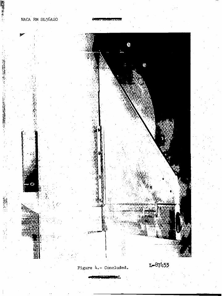
F igure 4.- Concluded. L-81&53
_I______’ ..
I . NACA RM SL56A20.
:
. .
.
. .
.
be* -.
‘,. ,i
:, ::3: ‘.N.$
“# T-:$2). . .
Q , *g $ 1’: 0” I,4 0 0
,G $ dn :,g
! *
;:. I., ,I
.I
,’
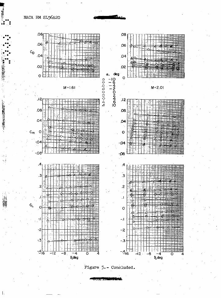
Figuke 5.- Variation of the basic coefficientg with control deflection for the 20-percent balance control. Flagged symbols denote wheel off. '. ', '
q Q ,‘.
. . : :
. . . l
.
. . E .
.
69 I’ .
.‘,.,i. ,.. .I
:
g
$4
‘$1’
” ~
.j
f
f‘
: ,. I. !L.. ‘?I r: 11. :;
:’
;
,j
a
_* ;
.‘
I
NACA RM SL56A20
8, deg
F igure 5*- Continued;
i!
1
0
b *. ‘7,. . .
=. :
z . . . .
.
. . ‘T .
.
’ . . ;. .
;,. .
;;..
$. =
! .n
P
*’ 1)
,$:
i2.a
j
:
4
.$
01
f k;
.Q
t
;: [
ih$l
‘: ]
c, .:.’ I
,. i;
‘: hp ‘6: ” p
d I*‘<
NACA F&I SL56A20
CD
C m
,’ c,
ww Weg
.08 -
M= 2.01
.08
Figure 5.- Concluded.

‘.
. =
= .
=
. .
.
0‘
:
.<‘.
?. ‘..a
: ,~.
;
‘, ,‘.
mcA m &5Q20 emhmmwa
ch
c&l -4
40 6
IO
‘76 -12 -8 -4 0 4 -16 -12 -8 -4 0 4
Meg
Figure 6.- Variation of,the basic coefficients with control dkflection for the 28-percent balance control. Flagged symbols denote wheel off.
- -
CZ
deg a, 0. cl 0.
.2 A
- ?. -2:
0 4.. 6
IO
-12 -8 -4 0 4 S,.deg
:-.- St- qz,. - I. i” 1 .~ ,.__ ~ l ;*-.‘o l ** l ** .
-12. .-8 -4 0 4 6, deg
.-
I
Figure 6.- Continued.
0 I’ . -:
E 52. F ul P g
I

NACA RM SL$A20
.
. . CD
4 ,. !. ‘,I 1..
a,
M=2.01
Figure 6.- Concluded.

. . . . . . _. : .: 8 _- j ys, * ~1.. ..-; l .
‘h-
-12 --8 ‘.-4 0 -4
s, deg s, $3
a, deg n -4 : b -2.
: 0 4
:: 1:
Figure 7.- Variation of basic coefficients with control deflection for 36-percent balance. Flagged symbols denote wheel off.
. . +qj
.I

: -,, ._ ’ ‘. -=*;L.- _.,
.08
-.I’6
-24 .- . -16 -12. x-8 -4 0 4
S;-dizg
a, ‘deg
n --4
$ ..: -A ij A IO
_, _. : ..?.‘ (1 . .‘. . . . l ** l .0
.I2 -- --
.08
.04 -__-~ szY!EEq-__---- --- --- ------ zzzz=zzBGz==
0
-.04-
-.08
-.I6
-.24 -16 -12 -8 -4 0 4
S, dw
Figure 7.- Continued. .

T ,! (1 r$
l .*
l i . . . . /’ . .
. . . . .j.. ; .’ . 7% c?i p: 4 :’ ,p!
Y
I
-‘.
NACA m ~~56~20
M=l,61
Cm
‘36 -12 -8 -4 0 4
6,deg
Figure 7*- Concluded.
‘M=2.OI
’
,
-1.2 -8 -4’ 0 4 ’ Bdes
l ..* . . . . NACA RM ~~56~20 r(nnTwl-nn 4--
l .- . . ..** . . l .- . .
. . ‘,,. . L -. j-1 i.;L 8:.
:
8.
4’
>.
I.,
.,; .- .., 1.’
.,
8 ,deg
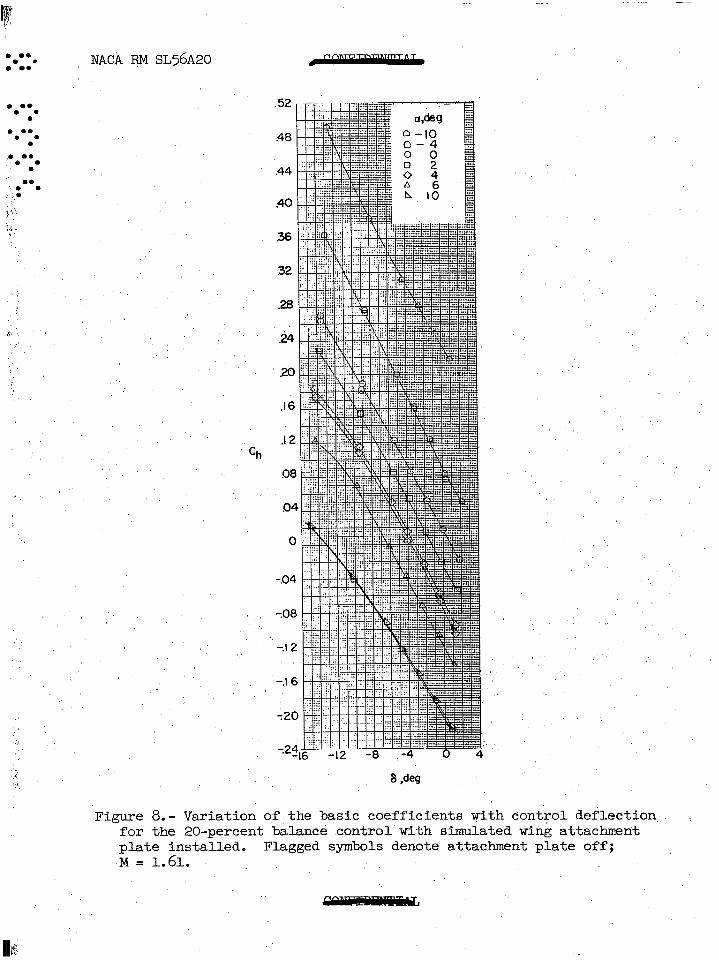
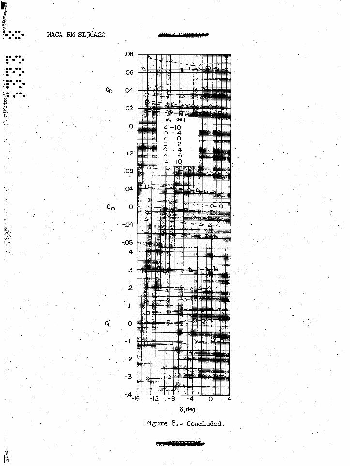
Figure 8.- Variation of the basic coefficients with control def;lection for the 20-percent balance control with simulated wing attachmerit plate installed. Flagged symbols denote attachment plate off; M= 1.61.
.:

_ -: :..:,. ., ,:;i;,.. -“.~~:-&~&~~-:“’ .,‘Y .. :. :-r.,.~A~~r~~;-:-~~~*~- l ” ,; . : .*: .*: l **
-, ~-.Fs~q-&g!.j l *. . . .
. I. . . . mx m sL56~20
‘0, . . . . . l .
:*:* . ‘. .
9.. . . s.. . h 6 .
B,. ..* , ,p l
5” .,
g,
‘5
:
I. ._ 1 !
*
.’ ,,,
:
i&
k.*:;
t\,:,,:: ,:’ 1 . .
. . ;
Gil
I:
CL
.06
04
.02
.I 2
.08
04
704
-.08 .4
.3
.2
.I
0
-.I
,-.2
-.3
h ,deg
Figure 8. - Concluded.‘
m 5’ f 6, .? :*. . . . . . . . ‘. .’ . ;y’.. J. . . . . . I. : :;, ,.” / i- 9
-.
I, .. ~,’ ‘.
NACA RM ~~56~20
i.
a, deg : :, ‘,
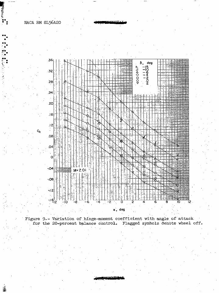
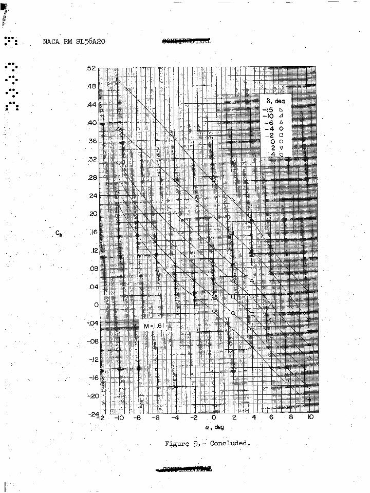
Figure 9;- Var,iation of,hinge-moment coefficient with angle of'attack for the 20-percent balance cdntrol. Flagged sy-mbols'den&e wheel off.
.' ,'
‘.
:
I,, jr i
>’
l . . . .
. .
. . . . .
.
. . . .
.
. . . .
.
. . . . ‘. :
,;
I .
‘.
.’ ,
I’.:.
NACA F&I SL56A20
/ ch
Figure 9.-' Concluded.
I 2 I i 6 ‘i, ”
. . . .
. . .
. . . . .
.
. . . .
.
. . . .
.
NACA
. . . . . .’ . . .e 6.0 : ,p,
RM ~~56~20 -,
. . -6 -4 .-2 0‘ 2 4 6 8 ,I0 12
a, deg
Fi.gu.r& lO.- Variation of hinge-moment coefficient with &gle of 'attack for the 28-percent balance control. Flagged symbol& denote wheel off.
e
114

- F I “i b S?h $1. . . . . NACA m ~~56~20 gnnm-*- . . . . ..i
’ . . ,. . .
. . . .
.
- .* 7. .
.
-,,.*- l 0. .
f:. G :(
., .’
ch
:‘: 1”*,
3.
a, deg
Figure lo.- Concluded.

!BJ- ...<F:.‘- I > ..- l l . . : .*: .*: l *o : :
-g&?&&II
..- r:. A. I
.
ch
-. Q, deg .’
Figure 11.- Variation of hingelmoment coefficient with angle- of attack for th? 36-percent balance control.-. Flagged symbols denote wheel off .
. /
.
. . . . .
. .
. .
.
. .
. . .
. .
.
.?
1? . .
. .
. .
, li
N A C A R M ~ ~ 5 6 ~ 2 0
,’ ;,
,.
.a , d e g F igu re 1 1 .~ C o n c l u d e d .

.: . .
..: . *. . . . . . .
‘.. .
.
. . .
:.
if‘.
:
,p-
‘b.,
NACA RN ~~56~20
Cm
.’ j l-4 L y,. ::
i
I IN : ‘. ;
I/i , Y .:i, .‘.,:::;... I> .i:‘~,‘~,j$
I -!
‘:’ .+I ,.. I I ,.‘I
! If’ II
rl”
.::‘,, ‘I ‘1)
i ‘!. :;! ;,,, j’~l /f I I
Ci
a,deg ’
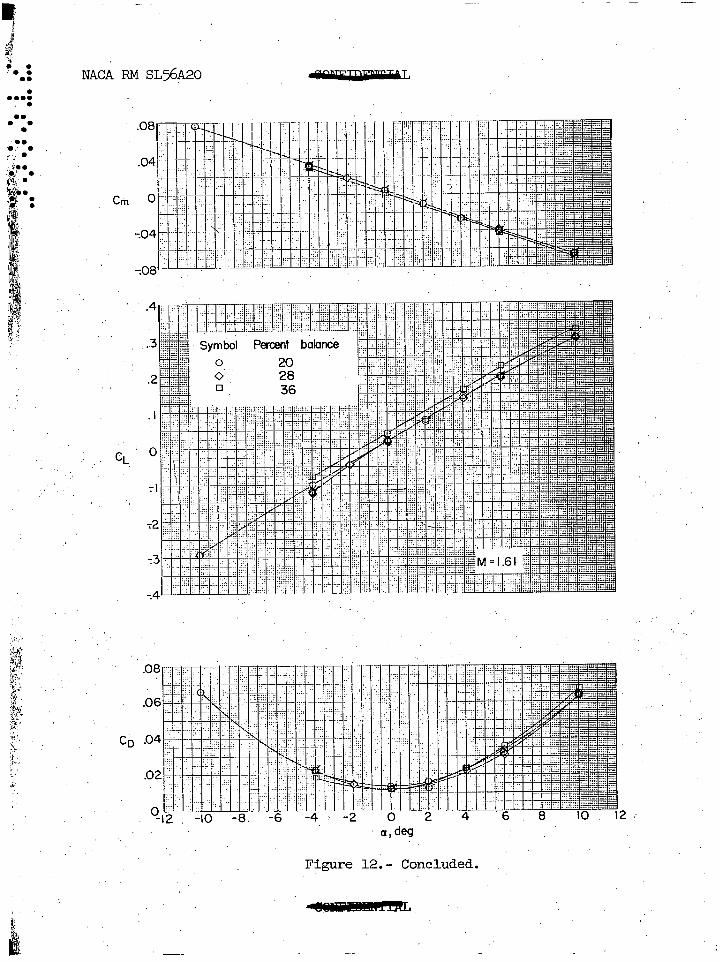
Figs-e 12.- Variations of wing lift, drag, and pitching-moment coeffi: ', cients with angle of attack. Flagged, symbols denote wheel 'o?f; 6 = O".
-
B ,.. 3 .: . . NACA FtM SL56420 . . . . .
. . 0. l .
‘.. ‘..- . :.; .
Cm
CL
a,deg
Figure 12.- Concluded.
-- F d
I.
. l NACA RM ~~56~20' .'J
..: . t- . '0 . . . -i, . .*
ch
.-I2 -8 -6 4 -2 0’ 2 4 6 8 IO I2 \’
a1 Ml
Figure, (13. - Effect of the simulated wing attachment -@ate on the variation of the hinge-moment coefficient with,angle of attack for the 20-percent balance control. Flagged symbols denote attachment plate off; M =.1.61.
.

,, : . ‘.
i I ,, _: 1 1. I; “ . . “,‘.“,
‘, ,~ I ;J,:’
., ., . ” :: ‘~,_ ~
_...