nab audio recording and reproducing ......nab audio recording and reproducing standards for audio...
TRANSCRIPT

NAB AUDIO
RECORDING AND REPRODUCING
STANDARDS FOR
AUDIO CASSETTE TAPE SYSTEMS
The NAB Recording and Reproducing Standards Committee w,as originally organized in 1941. Standards proposals issuing from the Committee have been adopted by the Board of Directors in 1942, 1949, 1950, 1953, 1964 and 1965. The Standards contained herein were adopted by the Board on June 16, 1972.
These standards and recommended good engineering practices are for the guidmce of the braadcasing industry, and represent the contributions of many of the nation's authorities on the various phases of recording as used by the industry. The NAB Recording and Reproducing Stand- ards Committee has also benefited by contributions made by several international organizations. The committee was open to participation by any interested individual or organization and con- sisted of representatives from the manufacturers, broadcasters and producers. Close liaison was m,aintained with other organizations (as well as foreign countries) to insure the maximum degree of coordinated understanding and recommended standardization, to permit interchangeability and, a t the same time, to embrace the latest technologioal advances of the art.
Nothing in these standards prohibits or discourages continued progress or advancement of the art. On the contrary, the standards are intended to provide stimulus for continued scientific exploration in the field of recording. It is anticipated that when new techniques and develop- ments are evident the NAB Recording and Reproducing Standards Committee may request sub- missions thereon looking toward any needed amendments and additions to keep pace with the ar t as it affects all forms of AM, F M and TV broadcasting.
THE NATIONAL ASSOCIATION OF BROADCASTERS 1771 N Street, N.W., Washington, D.C. 20036

The following organizations contributed to the formulation of these standards:
Spotmaster, Silver Spring, Maryland Sparta East Rockville, Maryland Sono-Mag Corporation, Bloomington, Illinois The Telex Corporation, Minneapolis, Minnesota Radio Corporation of America, Camden, New Jersey American Broadcasting Company, New York Columbia Broadcasting System, New York National Broadcasting Company, New York Public Broadcasting Service, Washington, D.C. Cybrix Corporation, Woodland Hills, California International Tapetronics Corp. Bloomington, Illinois Gates Radio Company, Quincy, Illinois Tele-Tape Productions, New York Nortronics Company, Inc., Minneapolis, Minnesota Marathon Broadcast Equipment Sales Co., West Boylston, Mass. Audio Devices, Inc. Glenbrook, Connecticut Ampex Corporation, Redwood City, California Philips Broadcast Equipment Corp., Montvale, New Jersey Schafer International, Chatsworth, California Minnesota Mining & Manufacturing Co., St. Paul, Minnesota U.M.C. Electronics Co., North Haven, Connecticut Ampro Corporation, Camden, New Jersey Gray Research, East Hartford, Connecticut Northwestern Technology, Inc., Bellingham, Washington Conrac Co~poration, Long Island City, New York

NAB AUDIO CASSETTE RECORDING AND REPRODUCING STANDARDS
I. MECHANICAL SPECIFICATIONS
1.05 Cassette Size
It shall be standard that 'there be a co-planar magnetic tape cassette physically identified and designed as shown in Figures A, B, and C, with a window area as specified in Figure C.
1.10 Tape Thickness
It shall be standard that the thickness of the magnetic tape for use in an NAB Audio Cassette be 800 micro inches (20.3 microns) maximum and 600 micro inches (15.2 microns) minimum.
1.15 Tape Width
I t shall be standard that the magnetic tape and leaders for use in an NAB Audio Cassette be 0.150 + 0.000, - 0.002 inches (3.81 mm + 0, - 50.8 microns) wide.
1.20 Standard Tape For Measureme.nts
The stmdard measurement tape shall be equivalent to 3M magnetic tape type # 277. This is a 500 micro inch (12.7 microns) tensilized polyester backed tape with a 200 micro inch (5.1 microns) low noise oxide coating. The tape has a minimum yield strength of 1.5 pounds (.650 Kg) a t 57% elongation under environmental test conditions. (see Section 1.80)
1.25 Tape Wind
It shall be standard that the magnetic tape be wound on both hubs within the cassette with the magnetic coating facing out from the hub and out of the cassette head openings and with the tape travel directim as specified in Figure D.
1.30 Tape Length Within Cassette
It shall be standard that an NAB Audio Cassette labeled as "NAB-300" contain 295 rt 5 feet (89.9 & 1.52 meters) of splice free magnetic tape. The "NAB-150" cassette shall contain 150 * 5 feet (45.7 + 1.52 meters) of splice free magnetic tape.
1.35 Cassette Head Shield
I t shall be standard that an NAB Audio Cassette contain a hum reducing magnetic shield behind the pressure pad as located in Figure D.
1.40 Pressure Pad
I t shall be standard that an NAB Audio Cassette have a pressure pad which is located and sized as described in Figure D. The pressure the pad exerts on the record/play head, when placed in the cassette in accordance with Figure E, shall be 11.4 to 34.1 oz/in2 (0.5 to 1.5 gm/mm2).
1.45 Cassette Torque
It shall be standard that the maximum friction torque of the full hub, in the cassette be 0.28 oz in (20 gm em). The maximum friction torque of both hubs measured in the cassette itself a t the nearly full hub shall be 0.38 oz in (27 gm cm). With the holdback torque of 0.11 oz in (8 gm
'Record/play a s used in these standards may be either a record head, a play head, or a combination rec- ordtplay head.
3

cm) applied to the nearly empty hub, the required maximum torque to be applied to the nearly full hub shall not exceed 0.78 oz in (55 g m cm).
1.50 Cassette Leaders
1.150.01 It shall be standard that an NAB Audio Cassette have a leader on each end of the tape having a minimum light transmittance of 75 % ,and that the tape have a maximum light trans- mittance of 5% when using a light source having a color temperature of 2000 & 200" K and using a silicon phototransistor for detection.
1.50.02 It shall be standard that the leader be 12 to 15 inches (30.48 to 38.10 cm) long with a typical thickness of 0.0015 inches (38.1 microns).
1.50.03 I t shall be standard that the leaders not part from the hub with a force of 2.20 lbs (1000 grams) under operating environment.
1.50.04 It shall be standard that the leader-to-tape splice not separate with a force of 1.54 lbs (700 grams) under operating environment.
1.55 Tape Position and Travel Direction
It shall be standard that the magnetic tape position and travel direction in the cassette head openings correspond to Figure D.
1.60 Cassette Breakage
I t shall be standard that an NAB Audio Cassette withstand 10 random drops of 12 inches (30.48 cm) onto concrete without causing functional damage.
1.65 Track Designation
It shall be standard that the track numbering be as shown in Figure G.
170. Cassette Support Planes
It shall be standard that the cassette be supported by the record/play instrument on only the cross hatched areas in Figure B designated a s support planes.
1.75 Label
It shall be standard that the label be located on side one only and shall fit within the area defined in Figure C.
The label shall include the following:
Side 1 designation, manufacturer, NAB designation (NAB-150 or NAB-300 per paragraph 1.30) and a blank area for content identification.
1.80 Cassette Environmental Conditions
Test environmental conditions are 70 & 5' F (21 + 3" C) and 50 + 10% relative humidity.
Operating environmental conditions shall be 20 to 125" F (- 7 to + 52" C) and 5 to 85% relative humidity non-condensing.
Storage environmental conditions shall be a maximum of 125" F, minimum - 40" F (+ 52", - 40" C) and maximum 85% relative humidity. After a period of 24 hours storage a t these ex- tremes and then normalized a t the test environment, the NAB cassette shall meet the NAB specifi- cation.
11. MECHANICAL SPECIFICATIONS FOR CASSETTE TRANSPORT
2.05 Transport Cassette Acceptance
I t shall be standard that the transport accept the standard NAB Audio Cassette.

2.10 Tape Speeds
It shall be standard that the tape speeds be 1% and 334 ips + 0.3% (4.76 cm/s & 9.53 cm/s t 0.3%). ...
2.15 Flutter and Wow
It shall be standard that the flutter and wow not exceed 0.2% NAB weighted rms in the play mode a t either speed.
2.20 Tape Guides
I t shall be standard that the tape guides have a width of 0.151 2 0.001 inches (3.84mm + 25.4 microns) and be centered on the nominal centerline of the cassette within 0.010 inches (254 microns). Two guides shall be provided, one located each side of (but not necessarily adjacent to) the record/play head.
2.25 Head Configuration
I t shall be standard that the magnetic record/play head be l/s track 4 track in-line. The erase head shall be y2 track 1/4, track with l/z track covering tracks 1 and 2 and with l/s track covering track 3.
2.30 Head Track Dimensions
I t shall be standard that the track dimensions of the magnetic record/play head be in con- formity with the track dimensions shown in Figure F. (Track width is the effective track defined as the region of the common interface on the abutting pole pieces).
2.35 Head Penetration
I t shall be standard that the head penetration be in accordance with Figure E.
2.40 Head Phasing and Azimuth
I t shall be stmdard that the phasing between tracks 1 and 2 result in no more than 90" dif- ference at 10 kHz when the head is adjusted within 1 db of peak azimuth a t lY8 ips (4.76 cm/s). The head may be adjusted for optimum within the phase and azimuth loss limits.
2.45 Head Zenith
I t shall be standard that the head face be no more than 2" out of perpendicularity with respect to the cassette support planes.
2;50 Tape Wrap
I t shall be standard that the tape wrap extend a minimum of 0.030 inches (762 microns) on each side of the head gap.
2.55 Spindle Take Up Torque
I t shall be standard that the spindle take up torque during play or record mode be within 0.41 to 0.83 oz in (30 to 60 gm cm).
2.60 Fast Wind Torque
I t shall be standard that the fast wind torque be within the range of 1.39 to 3.47 oz in (100 to 250 gm cm).
2.65 Fast Wind Times
I t shall be standard th,at the minimum fast forward or rewind time of a machine be 30 seconds for an NAB 300 cassette.

2.70 Maximum Tape Tension
It shall be standard that the maximum tension exerted on the tape not exceed 1.32 lbs (600 gm) for any mode of operation.
2.75 Start-Stop Time
It shall be standard that the tape motion start and meet all applicable standards within 500 milliseconds. The tape motion s h ~ l l stop within 50 milliseconds from play speed.
2.80 Cueing Accuracy
It shall be standard that the machine cue and stop within 75 milliseconds of the leading edge of the primary cue tone in the play mode.
111. SYSTEM ELECTRICAL SPECIFICATIONS
3.05 Standard 0pe.rating Reference Levels
It shall be standard that the operating reference level be a recorded 400 Hz signal that pro- duces an rms short circuit tape flux per unit track width of 200 nWb/m a t lY8 and 3% ips (4.76 and 9.53 cm/s) speeds. (This is approximately 3 to 4 dB below 3% third harmonic tape distortion).
3.10 Cue and Function Tone Recorded Level
It shall be standard that the cue and function tones be recorded a t a .level which produces an output 15dB below the standard operating reference level.
3.15 Playback Equalization Time Constants
It shall be standard that the higher frequency equalization time constant a t 3% ips (9.53 cm/s) be 90 microseconds. The lower frequency equalization time constant shall be 3180 micro- seconds.
At 1% ips (4.76 cm/s) the higher frequency equalization time constant shall be 120 micro- seconds and the lower frequency equalization time constant shall be 1590 microseconds.
3.20 Signal-to-Noise Ratio (either audio ~ h a n n e l ) ~
I t shall be standard that a t 394. ips (9.53 cm/s) the signal-to-noise ratio be not less than 48 dB weighted (NAB) below standard operating level (Reference Figure H).
At lY8 ips (4.76 em/&) it shall not be less than 45 dB.
The foregoing figures shall include residual noise contributed by machine erasing and biasing functions.
3.25 Freque,ncy Response
It shall be standard that the system response be within the limits shown in Figure I.
' All recordings to be made on bulk erased tape.
"Weighted noise shall be measured using the weighting curve of figure H in the measuring circuik. This curve is based on the ASA "A" curve (ASA Standard S1.4-1961). The noise measurement shall be made using a tape pre- viously recorded with bias but with no signal. The reference level is to be established, with the weighting network inserted, a t 1000 Hz using the 1000 Hz noise reference level signal included for this purpose on the NAB Test Tape. The indicator meter shall have the dynamics of the Standard Volume Indicator (ASA Standard C16.5-1961) and the measuring system shall conform wikh a full-wave rectified average measurement law.
Frequency response measurements shall be made a t a level of a t least 20 dB below the standard operating reference level.

3.30 Control Tones
Seven control tones shall be standard-for use in NAB Cassette Machine control: 261 Hz, 408 Hz, 639 Hz, 1000 Hz, 1565 Hz, 2449 Hz, and 3833 Hz, each within a tolerance of 4%.
3.35 Primary Cue Tune
I t shall be standard that 539 Hz be used as the Primary Cue Tone on tracks 3 or 4 for both "address" and %on-address" services. A tone burst of 0.75 * 0.25 seconds shall be employed for the Primary Cue Tone, with the machine cueing a t the beginning of the tone a t play speed. An inhibit circuit shall be employed to prevent the operation of the primary cue tone sensor for a pe- riod of 2 seconds -t 0.5 seconds after machine start.
3.40 Secondary Cue Tone
It shall be standard that 1 kHz be used as the Secondary Cue Tone on track 3 as the "End of Message" and "Overlap" tone. There shall be no constraint on the length of the tone. The "End of Message" function shall operate by sensing the leading edge of the tone. (The "Overlap" function may be used to start the next programed event on the leading edge and drop the current even on the trailing edge).
3.45 Tertiary Cue Tone
I t shall be standard that 3833 Hz be used as the Tertiary Cue Tone on track 3 for special re- quirements, e.g. digital logging (coded numeric) or alphaneumeric (plain english) . For logging systems using FSK, 3833 Hz may be replaced with tones in the 2.5 to 5 kHz region.
3.50 Address Code
I t shall be standard that an 8-bit binary code for two digit addresses (0-99) be recorded on tracks 3 and 4.
A 261 Hz tone shall be employed for encoding the address in pulse groups of 8 cycles per group (making each group 30.64 milliseconds long).
A zero bit shall be defined as a tone burst on track 3 immediately followed by a tone burst on track 4. A one bit shall be defined as a tone burst on track 4 immediately followed by a tone burst on track 3. A single set of ssimultaneous tone bursts a t the leading edge of the code group on tracks 3 and 4 shall be recorded to denote the forward direction of the tape. A double set of simultaneous tone bursts shall be recorded a t the trailing edge of the address code group. (The reading of a double set of simultaneous tone bursts prior to the address code indicates a reverse motion of the tape) 6.
In address type service, the primary cue tone shall follow the address code.
3.55 Auxiliary Tones
It shall be standard that 408, 1565, and 2449 Hz be designated as Au~ili~ary Tones for use as required. (2449 Hz shall be eliminated if FSK tones in the 2.5 kHz region are used).
3.60 Track Code
It shall be standard that the following track configuration be utilized:
The Primary Cue Tone may be used on track 4 when it is desired to retain a semi-permanent cue (which must be bulk-erased); or on track 3 when i t is desired that i t be erased as a normal machine function. The sensor shall react to a Primary Cue Tone on either track 3 or 4 at play speed.
Y n example is shown in Figure J of a recorded code group, address 48, with directions sensing marker. A leading and YZ trailing in the forward direction. Immediately following direction sensing marker A is the most significant bit of the least significant digit. After the first four bits (which comprise the least significant digit) there follows the most significant bit of the most significant digit.

Stop Tone (non-address) -Tracks 3 and/or 4. Address/Stop Tone -Tracks 3 and 4. Secondary, Tertiary and
Auxiliary Tones -Track 3.
3.65 Crosstalk
It shall be standard that the,playback crosstalk be not less than 26 dB between tracks 3 and 4, and tracks 1 and 2 within the frequency range of 50 to 10,000 Hz.
The crosstalk shall be not less than 40 dB between tracks 2 and 3, 2 and 4, 1 and 4, or 1 and 3 within the frequency range of 50 to 10,000 HZ.=
3.70 Transient Noise
It shall be standard that any transients generated within the machine result in an oscilloscope measurement a t least 40 dB below the standard operating reference level.
IV. TEST TAPE SPECIFICATIONS
There shall be two NAB Audio Cassette Test Tapes, one for use a t 1% ips (4.76 cm/s) and one for use a t 3% ips (9.53 em/s) which shall conform to the following specifications.
4.05 Cassette and Tape
The cassette and tape shall conform with the requirements of Section I of this Standard except for tape length.
4.10 Track Width
All recorded tones shall be full track.
4.15 Tone Spacing
There shall be a 2 second interval between tones which may be used for voice announcements.
4.20 Tape Erasure
All tape shall be bulk erased prior to recording the test tones.
4.25 Recorded Level
All levels shall be as specified within a 0.5 dB.
All test tones specified in 4.35 having a level of - 20 dB shall be recorded so as to produce a uniform response when the test tape is reproduced through an ideal reproducing system. (See annex A)
In lieu of the + 0.5 dB tolerance specification, a a 3 dB tolerance specification may be used provided that the deviation from uniform response when the test tape is reproduced on an ideal reproducing system is supplied for each test frequency.
4.30 Frequency Accuracy
All frequencies recorded on the test tape shall be within 1% of the specified frequency when the tapes are reproduced
7 Since control tones are recorded at a level 15 dB below standard operating reference level, this re- sults in an effective crosstalk level from the control tracks to the program tracks of 55 dB below standard operating reference level.
8

4.35 Test Tape Format
Time Frequency (Seconds) ( H z )
639 400 400
10,000 ' 6,000 3,000 1,000
500 100 50
Blank 1,000
Blank 1,000 1,000 3833 3833 3833 639 639 639
Level ..
(DB) Function
Stop tone to cue tape Opearting reference level Calibration level Azimuth Frequency Response Frequency Response Frequency Response Frequency Response Frequency Response Frequency Response To allow meter scale adjustment Signal reference for signal/noise measurement Noise measurement segment Tone bursts for cue tests Tone bursts for cue tests Tone bursts for cue tests Tone bursts for cue tests Tone bursts for cue tests Stop tones Stop tones Stop tones

I 7 I ! ) / l- 2697
2* I
I THIS SURFACE AREA SHALL BE -------- -+ ---
FLUSH WITH BACK I
I \.\ I
A I -- - ' 4 o . 1 5 , Y- i; 3.177 f 3153
I I I
D I M E N S I O N S I N I N C H E S
WHERE TWO NUMBER ARE MENTIONED, THE UPPER ONE GIVES THE MAXIMUM, THE LOWER ONE THE MINIMUM DIMENSION.
FIGURE A
EXTERNAL DIMENSIONS

MIN. 0.178 IN. (4.5 MY)
I MAX. 4X 0.2% IN. (6.0 Y M ) - -
FIGURE B
SUPPORT PLANES

MU, O.M2 IN. ( 0 . 3 MM)
1 - 3.587 IN. I (91.1 MY) I
- 1 I
MAXIMUM LABEL AREA CROSSHATCHED 0 . 0 1 2 IN.
MAX' ( 0 . 3 MM)
MAXIMUM WINDOW AREA CROSSHATCHED
FIGURE C

I UPPER SUPWRT PLANE
LOWE'R SUPPORT PLANE
LOWER LIMIT OF TAPE BLACK AREA DESIGNATES THE DIMENSION WITHIN WHICH THE PRESSURE PAD SHALL HOLD THE TAPE IN CONTACT WITH THE HEAD AREA.
TAPE TRAVEL DIRECTION FOR PLAYBACK - FIGURE D
TAPE PATH DIMENSIONS AND TRAVEL DIRECTION
0.1575 0.1496 0.1300 0.1221
\ ,
I I
I I I
I I I I I I I ERASE HEAD
! REC/PLAYBACK PRESSURE
HEAD ROLLER
FIGURE E
HEAD PENETRATION DIMENSIONS IN RECORD/ PLAY MODE

HEAD TRACK
NOTE:
THE OUTSIDE EWES OF EFFECTIVE HEAD TRACK NUMBERS ONE AND FOUR
SHALL NOT OVERLAP THE TAPE GUIDE AREA BY MORE THAN 0.002 INCHES.
FIGURE F
HEAD TRACK DIMENSIONS
- - ----PLAY TAPE MOTION-- - - 4
CONTROL TRACKS 3
Z(R1
PROGRAM TRACKS I I L )
VIEW ON THE COATED SIDE
NOTE: -- FOR MONOPHONIC OPERATION COMBINE TRACKS ONE AND TWO.
FIGURE G
TAPE TRACK DESIGNATION

I ! ! ! I ! ! ! ! I ! ! ! ! ! ! ! ! ! ! " ? ! ! ! ! ! ! ! ! ! ! ! " ! ' l l l " " l l ~ ' l l


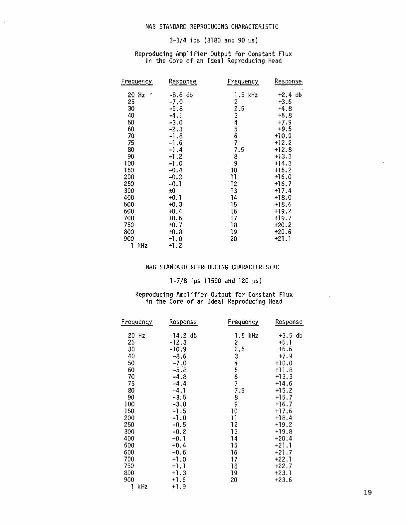
NAB STANDARD REPRODUCING CHARACTERISTIC
3-3/4 i p s (31 80 and 90 us)
Reproducing Ampl i , f i e r Output f o r Constant Flux i n the Core o f an Idea l Reproducing Head
Frequency
20 Hz ' 2 5 30 40 50 60 70 75 80 90
100 1 50 200 2 50 300 400 500 600 700 750 800 900
1 kHz
Response
-8.6 db -7.0 -5.8 -4.1 -3.0 -2.3 -1.8 -1.6 -1.4 -1.2 -1 .o -0.4 -0.2 -0.1 rO +o. 1 +O. 3 +0.4 +0.6 +O. 7 +0.8 +1 .o +1.2
Frequency
1.5 kHz 2 2.5 3 4 5 6 7 7.5 8 9
10 11 12 13 14 15 16 17 18 19 2 0
Response.
+2.4 db t3.6 +4.8 +5.8 t7.9 +9.5
+10.9 +12.2 +12.8 t13.3 +14.3 +15.2 +16.0 +16.7 +17.4 +18.0 +18.6 +19.2 +19.7 +20.2 +20.6 +21.1
NAB STANDARD REPRODUCING CHARACTERISTIC
1-718 i p s (1 590 and 120 us)
Reproducing Ampl i f i e r Output f o r Constant Fl ux i n the Core o f an Ideal Reproducing Head
Frequency
20 Hz 2 5 30 40 50 60 70 7 5 80 90
100 1 50 200 2 50 300 400 500 600 700 750 800 900
1 kHz
Response Freqliericy
1.5 kHz 2 2.5 3 4 5 6 7 7.5 8 9
10 11 12 13 14 15 16 17 18 19 20
Response
+3.5 db +5.1 t6.6 +7.9
+10.0 +11.8 +13.3 +14.6 +15.2 +15.7 +16.7 +17.6 +18.4 +19.2 +19.8 +20.4 +21.1 +21.7 t22.1 +22.7 t23.1 +23.6

ANNEX A 1. Ideal Reproducing System
The standard NAB Ideal Reproducing System is a theoretical reproducing system. I t consists of an "ideal" reproducing head and an amplifier the output voltage of which shall conform to the voltage-frequency curve of Figure K with constant flux vs frequency in the core of the head.2
The curve of voltage amplification vs frequency shall be uniform with frequency except where modified by the following equalizations :
ca) The voltage attenuation of a single resistance-capacitance high pass filter having am RC time constant tl.
(b) The inverse of the voltage attenuation of a single resistance capacitance low pass filter having an RC time constant t2. The curve expressed in decibels is represented by the following expression :
Na,, = 20 log,, ot1 v' 1 + (wt2) 1 + ( d l )
= 2T times frequency
At 3-3/4 ips tape speed tl = 3180 us and t2 = 90 us At 1-7/8 ips tape speed t, = 1590 us and tz = 120 us
2. Standard Reproducing System
I t shall be standard that an NAB Standard Reproducing System shall consist of a suitable tape transport, reproduce head and amplifier equalized to compensate for head losses insofar as possible and to produce a reproduce response from an NAB Standard Test Tape, within the limits specified in Figure I. It shall also meet the specifications for distortion, signal-to-noise ratio and other applicable parts of this Standard.
' An "ideal" reproducing head is defined as a ferromagnetic head, the losses of which are negligible. This means that the gap is short and straight, the long wave-length flux paths are controlled so ;that no low frequency contour effects are present, and the losses in the head materials are negligibly small.
' I t is recognized that the flux in the core of an "ideal" head is not necessarily the same as the surface flux on a tape in space for various reasons. Since most of these effects are not readily measured i t has been decided to base this standard on "ideal" head core flux rather than surface induction.
Vt is recommended tha t the Reproducing System response roll off a t the rate of a t least 6 db per octave beyond the frequency limiks shown in Figure I.

Copyright 1976
National Association of Broadcasters
Engineering Department National Association of Broadcasters
177 N Street, N.W. Washington, D.C. 20036