n99-am_detalii montaj foisor
TRANSCRIPT

Toll Free 1-888-658-1658 www.outdoorlivingtoday.com [email protected]
9 ft Naramata/Getaway Spa ShelterAssembly Manual
Outdoor Living Today
Thank you for purchasing a Naramata /Getaway Spa Shelter from Outdoor Living Today. Please takethe time to identify all the parts prior to assembly.
Safety Points and Other ConsiderationsOur products are built for use based on proper installation and normal residential use, on level ground. Please follow the instruction manual when building your shelter and retain the manual for future maintenance purposes.
Some of the safety and usage measures you may wish to consider include:-snow load ratings vary by geographical location. If heavy or wet snowfall occurs, it is advisable to sweep the snow off the roof(s).
-if the product is elevated, any structural and building code requirements are solely the customer's responsibility, and should be abided by.
-in high or gusty wind conditions it is advisable to keep the structure securely grounded. -have a regular maintenance plan to ensure screws, doors, windows and parts are tight.
Customers agree to hold Outdoor Living Today and any Authorized Dealers free of any liability forimproper installation, maintenance and repair of any Outdoor Living Today products.
In the event of a missing or broken piece, simply call the Outdoor Living TodayCustomer Support Line @ 1-888-658-1658 within 30 days of the delivery of your purchase. It is our commitment to you to courier replacement parts, free of charge, within 10 business days of this notification. Replacement parts will not be provided free of charge after the 30 day grace period.
Version #3Sept 16, 2009

Toll Free 1-888-658-1658 www.outdoorlivingtoday.com [email protected]
Parts Lists:A. Wall Section4 - 3 1/2” x 3 1/2” x 92” long Posts4 - Upper Railing Sections 13”h x 101”long (Getaway = 10”high- wood)8 - 1 1/2” x 3 1/2” x 54” Top Plates (cut on 45 degree on 1 end)
B. Roof Section1 - Skybox - 5 1/2” high x 37” x 37” 4 - 2x4 Corner Rafters with Side Cleats- 58 3/8” long4 - 2x4 Center Rafters with Side Cleats - 42” long8 - 2x4 Mid Rafters (without Side Cleats) - 42” long4 - Left Side Roof Sections 4 - Right Side Roof Sections1 - Bundle of Filler Shingles (18” long & 4 Top Row Trimmed)32 -Regular Cedar Roof Ridge Caps4 - 10” long Cedar Roof Ridge Caps with Roofing Paper attached4- 42” long x 3” wide Flex Flashings for Skylight4 - 1/2” x 3 1/2” x 36” long Skylight Trims
Assembly Time: 1 Day (does not include site preparation)
Specifications:Outside Post to Post Dimensions108” w x 108” w Inside Post to Post Dimensions101” w x 101”wOverall Dimensions with Roof Overhang120”w x 120”w x 116”hOverall Weight750 Lbs
Thank you for purchasing one of our Naramata/Getaway Spa Shelters.Please take the time to identify all the parts prior to assembly.
Page 2
9’x9’ NARAMATA HARDWARE SHEET
2 1/2”
Note: screws and nails shown actual size.
1 1/4”Shingle
Hardware Kit (Provided)
4”
Square Drive Bit
Simpson StrongTie x 4
1 1/2”
Wooden RafterCorner Block
Washer
4 - Corner Post/Top Plate Cap (Naramata Only)
8 - Corner Brackets (BlackAluminum) (Getaway = WoodBrackets)
1 1/4”
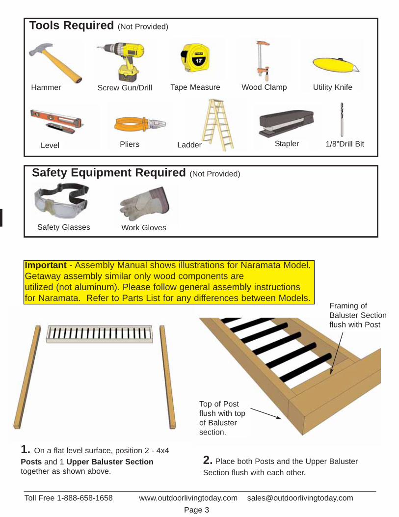
1. On a flat level surface, position 2 - 4x4Posts and 1 Upper Baluster Sectiontogether as shown above.
2. Place both Posts and the Upper BalusterSection flush with each other.
Top of Postflush with topof Balustersection.
Framing ofBaluster Sectionflush with Post
Important - Assembly Manual shows illustrations for Naramata Model.Getaway assembly similar only wood components are utilized (not aluminum). Please follow general assembly instructionsfor Naramata. Refer to Parts List for any differences between Models.
Safety Glasses Work Gloves
Safety Equipment Required (Not Provided)
Ladder
Screw Gun/Drill Tape MeasureHammer Wood Clamp
Level Pliers
Tools Required (Not Provided)
1/8”Drill Bit
Toll Free 1-888-658-1658 www.outdoorlivingtoday.com [email protected] 3
Utility Knife
Stapler

Toll Free 1-888-658-1658 www.outdoorlivingtoday.com [email protected] 4
3. When Post and Baluster Section areposition correctly, fasten together with 4 - 2 1/2” screws per side.
Hint- screw both front sides (2 screws perside) flip assembly over and complete theother sides.
2 1/2” screws here.
4. Complete 2nd Post/Upper BalusterAttachments.
5. Standing the Post/Baluster Assemblies will beeasier with 2 extra helpers. Carefully raise one ofthe section up first and steady with 1 helper.Raise the second assembly up and steady withyour other helper.
6. While both sectionsare held in place byyour helpers, locate a3rd Upper BalusterSection and placebetween both sections. Have your helper standclose to your end toassist you with the lifting of the BalusterSection while still keeping the assembly steadied.
Place assembliesapprox. 9 feetapart.
You can find theSquare Drive Bit forthe screws in withthe Hardware KitBag.
Toll Free 1-888-658-1658 www.outdoorlivingtoday.com [email protected] 5
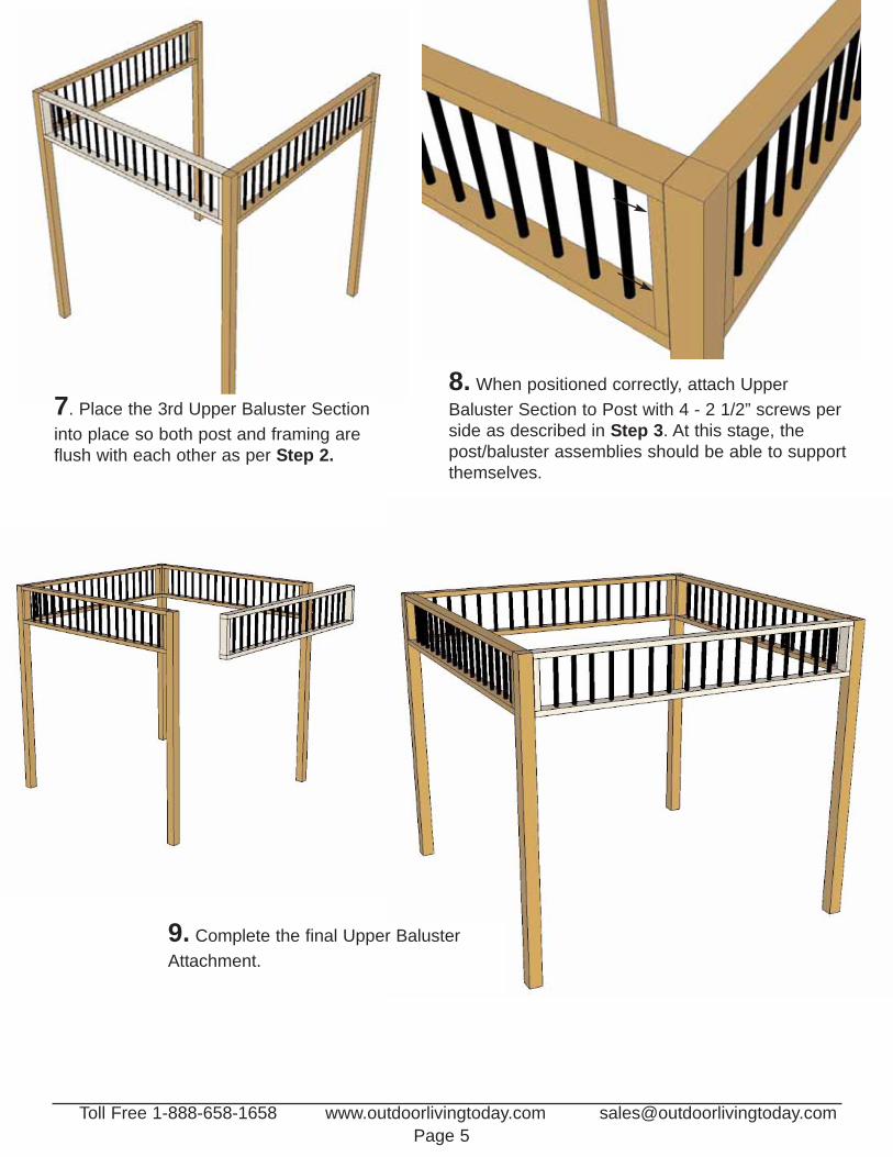
7. Place the 3rd Upper Baluster Sectioninto place so both post and framing areflush with each other as per Step 2.
8. When positioned correctly, attach UpperBaluster Section to Post with 4 - 2 1/2” screws perside as described in Step 3. At this stage, thepost/baluster assemblies should be able to supportthemselves.
9. Complete the final Upper BalusterAttachment.

Toll Free 1-888-658-1658 www.outdoorlivingtoday.com [email protected] 6
10. Next, attach Top Plates. The TopPlates will tie your post and balusterstogether. There are 2 Top Plates per side(left and right both with a 45 degree cut onthe end. Locate and position on top ofpost/baluster assembly.
11. Place Top Plate so the 45 degree cuton the end sits over the post approximatelyhalfway as illustrated above. When positioned correctly, attach to post/balusterassembly with 4 - 2 1/2” screws per piece.Make sure to place a screw from top plateinto post. Drill pilot hole to prevent splitting.
2 1/2” screw
2 1/2” screw
12. Position 2nd Top Plate on post/balusterassembly and fasten down as per Step 11.

Toll Free 1-888-658-1658 www.outdoorlivingtoday.com [email protected] 7
13. Position 3rd TopPlate down and attachto post/baluster assemblies asdescribed earlier.
3rd TopPlate.
Both Top Plates shouldbe flush and sitting onthe post equally.
14. Complete remainingTop Plate attachments working in a clockwise direction.
When completed, you are ready tostart Corner Bracket Attachments.
Toll Free 1-888-658-1658 www.outdoorlivingtoday.com [email protected] 8
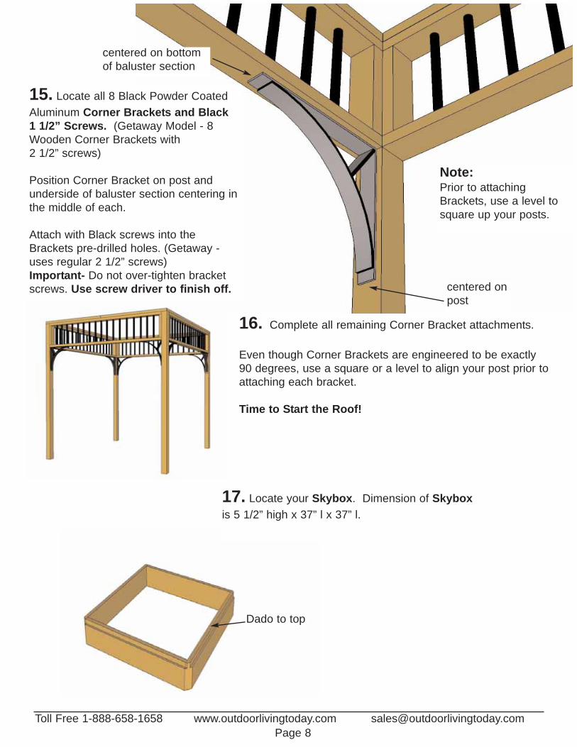
15. Locate all 8 Black Powder CoatedAluminum Corner Brackets and Black 1 1/2” Screws. (Getaway Model - 8Wooden Corner Brackets with 2 1/2” screws)
Position Corner Bracket on post andunderside of baluster section centering inthe middle of each.
Attach with Black screws into theBrackets pre-drilled holes. (Getaway -uses regular 2 1/2” screws)Important- Do not over-tighten bracketscrews. Use screw driver to finish off.
centered on bottomof baluster section
centered onpost
Note:Prior to attachingBrackets, use a level tosquare up your posts.
16. Complete all remaining Corner Bracket attachments.
Even though Corner Brackets are engineered to be exactly 90 degrees, use a square or a level to align your post prior toattaching each bracket.
Time to Start the Roof!
17. Locate your Skybox. Dimension of Skyboxis 5 1/2” high x 37” l x 37” l.
Dado to top
Toll Free 1-888-658-1658 www.outdoorlivingtoday.com [email protected] 9
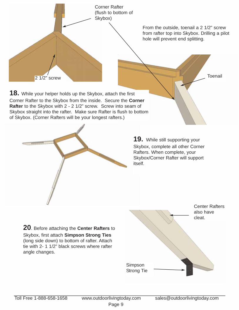
From the outside, toenail a 2 1/2” screwfrom rafter top into Skybox. Drilling a pilothole will prevent end splitting.
19. While still supporting yourSkybox, complete all other CornerRafters. When complete, yourSkybox/Corner Rafter will supportitself.
20. Before attaching the Center Rafters toSkybox, first attach Simpson Strong Ties(long side down) to bottom of rafter. Attachtie with 2- 1 1/2” black screws where rafterangle changes.
Toenail2 1/2” screw
Corner Rafter(flush to bottom ofSkybox)
18. While your helper holds up the Skybox, attach the firstCorner Rafter to the Skybox from the inside. Secure the CornerRafter to the Skybox with 2 - 2 1/2” screw. Screw into seam ofSkybox straight into the rafter. Make sure Rafter is flush to bottomof Skybox. (Corner Rafters will be your longest rafters.)
SimpsonStrong Tie
Center Raftersalso havecleat.
Toll Free 1-888-658-1658 www.outdoorlivingtoday.com [email protected] 10
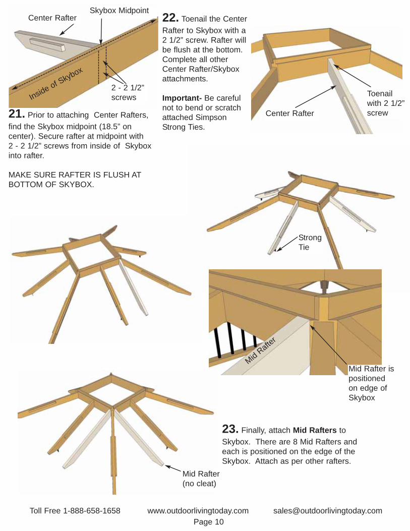
23. Finally, attach Mid Rafters toSkybox. There are 8 Mid Rafters andeach is positioned on the edge of theSkybox. Attach as per other rafters.
22. Toenail the CenterRafter to Skybox with a2 1/2” screw. Rafter willbe flush at the bottom.Complete all otherCenter Rafter/Skyboxattachments.
Important- Be carefulnot to bend or scratchattached SimpsonStrong Ties.
Toenailwith 2 1/2”screwCenter Rafter
Center Rafter
Inside of Skybox
StrongTie
Mid Rafter ispositionedon edge ofSkybox
Mid Rafter(no cleat)
MidRafte
r
21. Prior to attaching Center Rafters,find the Skybox midpoint (18.5” on center). Secure rafter at midpoint with 2 - 2 1/2” screws from inside of Skyboxinto rafter.
MAKE SURE RAFTER IS FLUSH ATBOTTOM OF SKYBOX.
Skybox Midpoint
2 - 2 1/2”screws

Toll Free 1-888-658-1658 www.outdoorlivingtoday.com [email protected] 11
24. Picture illustrated to leftshows all Mid, Center andCorner Rafter attachments.
Next Step...
Positioning the rafter sectionson the post/baluster section.
25. With 2 or 3helpers, carefully liftup your completedrafter section andplace on top of yourpost/baluster section.Position Rafters intheir approx. location.
Birds eye viewof rafters sittingon top plates.
26. When inside the Naramata, the CenterRafter Simpson Strong Tie should sit flush againstTop Plate and be centered between posts. Checkall Center Rafter locations and when positionedcorrectly, screw the Strong Ties into Top Plate /Baluster with 2 - 1 1/2” Black screws per side.
SimpsonStrong Tie
Center Rafter
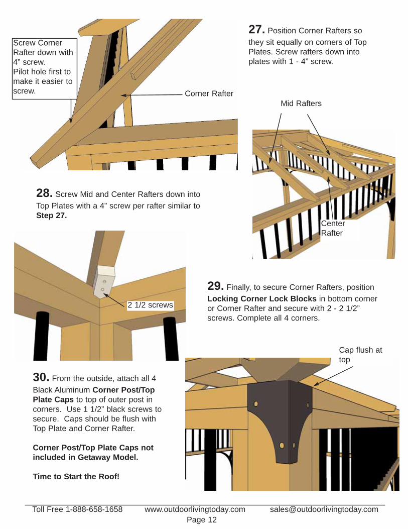
27. Position Corner Rafters sothey sit equally on corners of TopPlates. Screw rafters down intoplates with 1 - 4” screw.
Corner Rafter
Screw CornerRafter down with4” screw.Pilot hole first tomake it easier toscrew.
Mid Rafters
28. Screw Mid and Center Rafters down intoTop Plates with a 4” screw per rafter similar toStep 27.
CenterRafter
29. Finally, to secure Corner Rafters, positionLocking Corner Lock Blocks in bottom corneror Corner Rafter and secure with 2 - 2 1/2”screws. Complete all 4 corners.
30. From the outside, attach all 4Black Aluminum Corner Post/TopPlate Caps to top of outer post incorners. Use 1 1/2” black screws tosecure. Caps should be flush withTop Plate and Corner Rafter.
Corner Post/Top Plate Caps notincluded in Getaway Model.
Time to Start the Roof!
Toll Free 1-888-658-1658 www.outdoorlivingtoday.com [email protected] 12
Cap flush attop
2 1/2 screws

Toll Free 1-888-658-1658 www.outdoorlivingtoday.com [email protected] 13
31. You will need a step ladder to complete the roofsection. Be Careful when working on the ladder!Lift and position the first Right Sided Roof Section intoplace on the rafters. (There are 4 Right and Left SidedRoof Panels).
32. Place Right Sided Panel so it sitsapproximately 1/2 way on the CenterRafter
33. Position roof so panel sits flush in DadoSlot of Skybox and is centered approximately1/2 way on Center Rafter.
34. When Right SIded Roof Panel is positioned correctly, attach roof panel to CornerRafter with 3 - 2 1/2” screws.
DO NOT SCREW ROOF PANEL DOWN TOCENTER RAFTER AT THIS POINT!
1/2 wayon rafter
SkyB
ox
Roof is sitting in dado slot andsitting 1/2 on Center Rafter
Center Rafter
3 - 2 1/2”screwsintoCornerRafter
Toll Free 1-888-658-1658 www.outdoorlivingtoday.com [email protected] 14
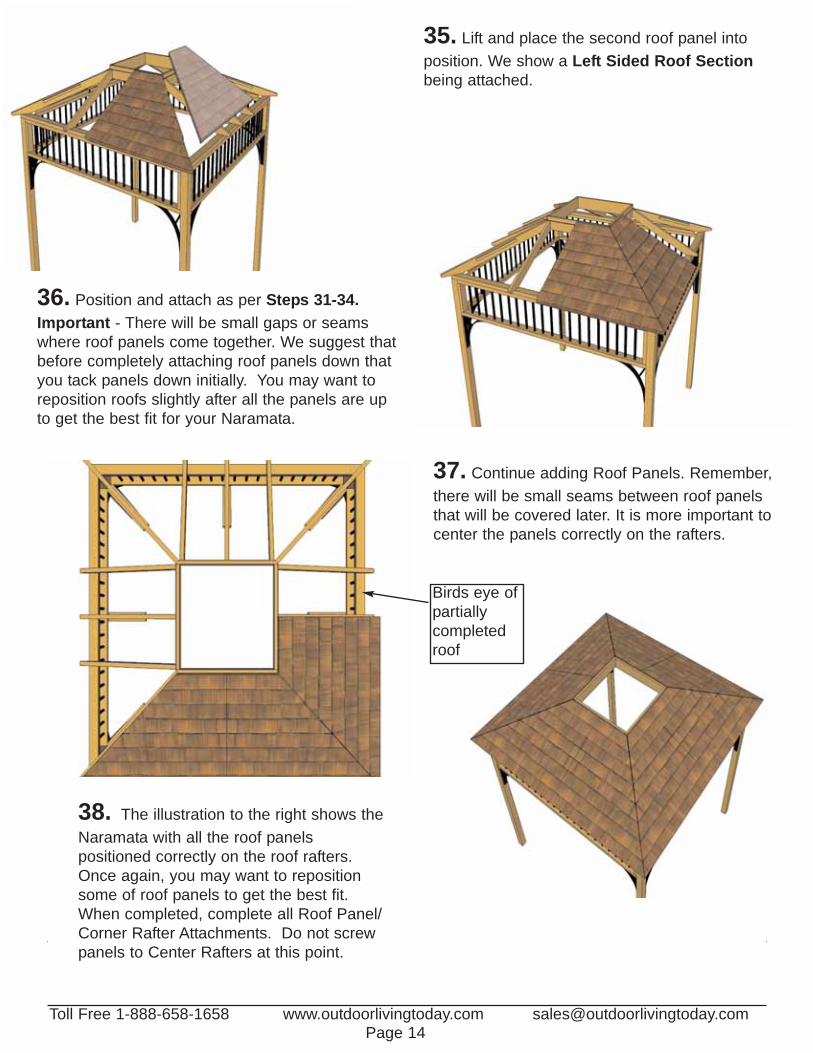
35. Lift and place the second roof panel intoposition. We show a Left Sided Roof Sectionbeing attached.
36. Position and attach as per Steps 31-34.Important - There will be small gaps or seamswhere roof panels come together. We suggest thatbefore completely attaching roof panels down thatyou tack panels down initially. You may want toreposition roofs slightly after all the panels are upto get the best fit for your Naramata.
37. Continue adding Roof Panels. Remember,there will be small seams between roof panelsthat will be covered later. It is more important tocenter the panels correctly on the rafters.
38. The illustration to the right shows theNaramata with all the roof panels positioned correctly on the roof rafters.Once again, you may want to repositionsome of roof panels to get the best fit.When completed, complete all Roof Panel/Corner Rafter Attachments. Do not screwpanels to Center Rafters at this point.
Birds eye ofpartiallycompletedroof
Toll Free 1-888-658-1658 www.outdoorlivingtoday.com [email protected] 15
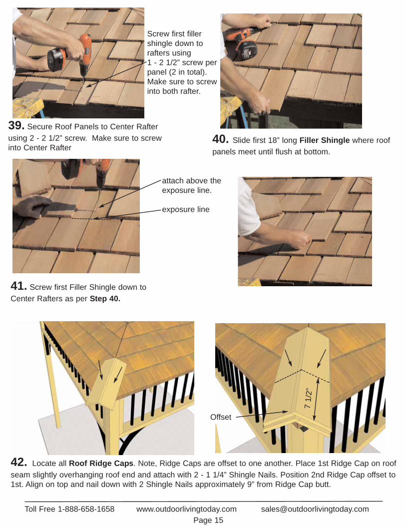
39. Secure Roof Panels to Center Rafterusing 2 - 2 1/2” screw. Make sure to screwinto Center Rafter
40. Slide first 18” long Filler Shingle where roofpanels meet until flush at bottom.
41. Screw first Filler Shingle down toCenter Rafters as per Step 40.
Screw first fillershingle down torafters using 1 - 2 1/2” screw perpanel (2 in total).Make sure to screwinto both rafter.
attach above theexposure line.
exposure line
42. Locate all Roof Ridge Caps. Note, Ridge Caps are offset to one another. Place 1st Ridge Cap on roofseam slightly overhanging roof end and attach with 2 - 1 1/4” Shingle Nails. Position 2nd Ridge Cap offset to1st. Align on top and nail down with 2 Shingle Nails approximately 9” from Ridge Cap butt.
71/
2”
Offset

43. Place 3rd Ridge Cap 7 1/2” up from butt of 2nd Cap and nail with 2 Shingle Nails approximately 9” from the butt. Make sure to alternate Ridge Cap offsets as you complete each row.Position and attach 4th Ridge Caps as previously described.
44. Complete remaining Long Ridge Caps. On top of the roof, carefully position Skylight/RoofFlashing on Skybox. Space evenly from side to side on Skybox making sure Flashing does not protude past the Skybox on the inside. Staple down to Skybox when in correct position.
71/
2”
71/
2”
45. Complete alignment and attachment of remaining Flashing Strips as per Step 44.
Toll Free 1-888-658-1658 www.outdoorlivingtoday.com [email protected] 16

49. Place 10” long Roof Ridge Cap over Skylight Trim. Align and Drill 2- 1/8” pilot holes in eachend of Cap. Carefully screw Ridge Cap down to Skylight Trim with 2 - 1 1/4” screws. Complete allcorners.
Toll Free 1-888-658-1658 www.outdoorlivingtoday.com [email protected] 17
Near end, Handtighten Screws to prevent cracking.
46.Prior to lifting your Skylight into place, carefullyremove the blue protective layer of plastic. Lift up andcarefully place the skylight into position on the Skybox.The Skylight is pre-drilled for your convenience. Use 8 - 1 1/2” black screws with neoprene washers toattach. Screw down so Skylight is snug only. Do notovertighten or Skylight will crack. Hand tighten only.
47. Position Skylight Trim to cover Flashing.Drill 1/8” pilot holes near both ends and attachwith 2 - 2 1/2” screws. Screw trims to rafters ifpossible.
Use 1 1/2”black screwswith neoprenewashersattached
Drill 1/8” Pilot Holein Skylight Trimprior to attaching.
48. Complete alignment and attachmentsof remaining Skylight Trims as per Step 47.
We hope your experience assembling your Spa Shelter has been both positive and rewarding.
We value your feedback and would like to hear back from you on how well we are doing in the following areas:
1. Customer Service2. On Time Shipping3. Motor Freight Delivery4. Quality of Materials5. Assembly Manual6. Overall Satisfaction.
Please call, write or email us at:
Outdoor Living Today PartnershipP.O. Box 96Sumas, Washington98295
Toll Line: 1.888.658.1658 | Fax: 1.604.462.5333 | [email protected] 18
The materials contained in this Assembly Manual maybe downloaded or copied provided that ALL copiesretain the copyright and any other proprietary noticescontained on the materials. No material may be modified, edited or taken out of context such that itsuse creates a false or misleading statement or impression as to the positions, statements or actions.
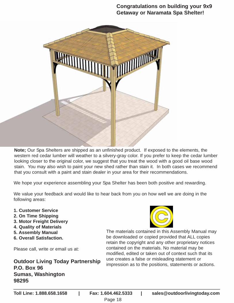
Congratulations on building your 9x9Getaway or Naramata Spa Shelter!
Note; Our Spa Shelters are shipped as an unfinished product. If exposed to the elements, the western red cedar lumber will weather to a silvery-gray color. If you prefer to keep the cedar lumberlooking closer to the original color, we suggest that you treat the wood with a good oil base woodstain. You may also wish to paint your new shed rather than stain it. In both cases we recommendthat you consult with a paint and stain dealer in your area for their recommendations.