n87-27248 - nasa · the reliability of the procedure is assessed through an analysis ......
TRANSCRIPT

N87-27248
NASTRAB APPLICATION FOR THE PREDICTION OF AIRCRAFT INTERIOR NOISE
Francesco Marulo
University of Naples
NASA Langley Research Center
Hampton, VA 23665-5225
and
Todd B. Beyer
NASA Langley Research Center
Hampton, VA 23665-5225
Abstract
The application of a structural-acoustic analogy within the NASTRAN
finite element program for the prediction of aircraft interior noise is
presented. The reliability of the procedure is assessed through an analysis
of the principle components involved in the fluld-structure coupling, and is
compared to simple structures with known theoretical results. Some refine-
ments of the method, which reduce the amount of computation required for
large, complex structures, are then discussed. Finally, further improvements
are proposed and preliminary comparisons with structural and acoustic modal
data obtained for a large composite cylinder, are presented.
Introduction
The prediction and reduction of aircraft interior noise are important
considerations for conventional propeller aircraft now entering the commercial
market as well as for aircraft currently being developed, such as the advanced
turboprop. Consequently, the interior noise problem is receiving attention
even during the first stages of the aircraft design process. , Also, the
need for laboratory tests on full scale^m_dels to validate new theoretical
prediction methods has been recognized. , The theoretical approach has
progressed throug_ _everal stages, beginning with very simple models of the
aircraft fuselage , and proceeding to very detailed methods and computer
programs which discretize the structure and the interior acoustic volume and
define the coupling characteristics therein. Among the several analytical
methods available, the finite element method has been chosen for this study
for several reasons. It is fully documented, available worldwide, and can be
used to model complex structural and acoustic geometries. The theory which
defines the finite element solu_!_ for fluld-structure interaction problems
is available in t_ _,terature, as is the practical application using
the NASTRAN code.-_-[8 l_nly recently has this approach been applied to
aircraft structures. , An analysis of the fluld-structure interaction
problem based on the finite element method and NASTRAN is presented in this
paper and compared with studies in the literature. The initial results are
very promising, however, some refinement of the numerical techniques may be
necessary (especially for large structures with many degrees of freedom) in
order to reduce computational costs and provide a cost-effectlve tool for use
during the final definition phase of aircraft design. This paper also
presents preliminary numerical predictions using both the structural and
acoustic finite element models to describe an actual aircraft fuselage model
266
https://ntrs.nasa.gov/search.jsp?R=19870017815 2018-07-17T03:45:31+00:00Z
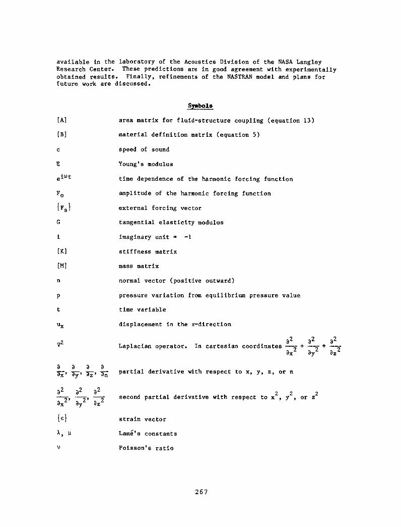
available in the laboratory of the Acoustics Division of the NASA Langley
Research Center. These predictions are in good agreement with experimentally
obtained results. Finally, refinements of the NASTRAN model and plans forfuture work are discussed.
[A]
[B]
C
E
ei_t
F o
{Fs}
G
i
[El
[M]
n
Ux
y2
3 3 3 3
32 32 32
2' 2'3x 3y 3z 2
I, 1J
S_bols
area matrix for fluid-structure coupling (equation 13)
material definition matrix (equation 5)
speed of sound
Young's modulus
time dependence of the harmonic forcing function
amplitude of the harmonic forcing function
external forcing vector
tangential elasticity modulus
imaginary unit = -I
stiffness matrix
mass matrix
normal vector (positive outward)
pressure variation from equilibrium pressure value
time variable
displacement in the x-dlrectlon
3 2 3 2 3 2Laplacian operator. In cartesian coordinates --+ _+ --
3x 2 3y 2 3z 2
partial derivative with respect to x, y, z, or n
2 2 2second partial derivative with respect to x , y , or z
strain vector
Lam_'s constants
Poisson's ratio
267

P
{o}
_XX
Txy, Tyz,
TXZ
[ ]T
ee
Subscripts
mass density
stress vector
axial stress in the x-direction
shear stress in the x-y, y-z, or x-z plane
angular frequency of harmonic forcing function
transpose matrix
double dot. Second time derivative
acoustic
normal direction
structure
Structural-Acoustic Analogy
It is possible to solve acoustic problems using structural code which
already exists in the Finite Element Method. The technique is based on a
structural-acoustic analogy which relates structural displacement to acoustic
pressure. Specific problems have been solved using this approach, 7-19 and
the theoretical development has been well documented. In this paper the
fundamental steps are included for the sake of clarity.
The scalar acoustic wave equation in terms of the variation of pressure
from the equilibrium pressure is
c _t 2(1)
which, in Cartesian coordinates is
Bx 2 By2 Bz 2 c2 Bt 2
(2)
The equation governing the equilibrium of stresses in a material in a
particular direction (x, for example) is
268

Bo @T _T _2uXX _ XZ XFx + + @z -- ps 3t 2
(3)
Equations (2) and (3) are mathematically similar, and an "analogy" can be
obtained if
ffivx ; T = • ffi p =-- ; Ux pxx xy 3y ; xz 3z s 2 =C
(4)
Thus, it is possible to solve acoustic problems using existing structural
analysis codes based on the di_l_ement formulation of the Finite ElementMethod, in particular NASTRAN. , "
In order to complete the analogy and give practical ideas as to its
NASTRAN application, consider the general stress-straln relationship,
{o}: tBl (5)
If we consider the displacement in the x-direction only (u v = u z = 0),
equation (5) can be written in terms of the relations (4) _s
Cxx --I BI2 BI3 0 BI5 0-- _Ux/_X
%
Oyy B22 B23 0 B25 0 0
°zz B33 0 B35 0 0
Txy I B45 0 _Ux/_y
Ty z SYMM. B55 0 0
1Txz @Ux/B z
where the terms Bij are arbitrary. However, it is often convenient to
choose Bi_ so that the matrix [B] is Isotropic and therefore invarlant forany coordinate system. This can be achieved in NASTRAN by using the card
which defines a linear, temperature-lndependent, isotropic material (MATI
card), and substituting the proper values for the material constants. For
example- the material definition matrix, [B], for the three-dimensional
problem 20 is
(6)
269

[B] =
), ), 0
),+2 p X 0
>,+21a 0
P
SYMM
0 0
0 0
0 0
0 0
tl 0
tl
where k + 2_ = i and P = I in order to obtain the general matrix given by
equation (6). Since the Lam6 constants X and P are
(7)
E_ E)' = (l+V)(l-2'o) ; _ = G = 21-('i'_)
(8)
the following values input with the MAT1 card
g = I x 1020 ; G = I ; _ = .5 x 1020 ; O =1
2c
(9)
define the acoustic analogy.
two-dlmensional case is
Similarly, the [B] matrix for the
BIE01101-v 2 0 (1-_).2
and the corresponding material properties are input as
(I0)
E = 2 x 10 -6 ; G = 1 ; _ = - 999999 ; P = __I (11)• 2
c
Using thls approach, equation (I) can be solved for many cases, and proves
especially useful when the geometry of the enclosure is irregular and cannot
be studied adequately using known results for simple geometries•
Finite Element Formulation and Validation Ex_aples
The equation of motion of an acoustic enclosure wlth rigid walls and no
forcing function can be written in terms of the Finite Element notation as
[Ma]{i_} + [Ka]{p } = {0} (12)
where [M a] _s the acoustic 'mass' matrix, [K a] is the acoustic 'stiffness'matrix and tp} is the vector of pressure values at the grid points. If the
pressure is harmonic, equation (12) becomes a classical elgenvalue problem
that can be solved using standard NASTRAN methods and the acoustic resonance
C

frequencies and acoustic mode shapes for any geometry can easily be
extracted. The validity of this formulation has been studied for cavities
with simple geometries which have straightforward theoretical solutions. For
the present paper two particular geometries have been studied, one having a
rectangular cross section and one with a circular cross section. A comparison
of the acoustic mode shapes and resonance frequencies for the 2-dimenslonal
cross section and the 3-dimensional volume derived theoretically and predictedusing the present NASTRAN formulation is tabulated in Table I. These data are
in general good agreement, with some small differences at higher modes where a
finer mesh may be necessary. For the NASTRAN formulation the QUAD2 membraneelement was used to model the cross-sectlonal area for the 2-dimensional case
and the HEXA2 solid element was used to model the 3-dimensional acoustic
volume. Figure 1 shows some of the acoustic mode shapes predicted using the22NASTRAN formulation and plotted using PATRAN-G post-processing capabilities.
Fluid-Structure Interaction
Theo
A complete description of the fluld-structure interaction problem, in
terms of finite element models of the structure and the enclosed acoustic
volume, is given by the following coupled equation of motion
iMs0j!-( pc)2A T M
L
4-
IK s A ]0 K a
m
u
P
where the matrix, [A], ensures the proper coupling between structural and
acoustic models. At a fluid-structure interface the boundary condition is
_n = -P_ (14)
where n is the normal, positive outward, unit vector at the interface and P is
the mass density of the fluid. For the present finite _l_ment application,
the force exerted by the structure on the fluid isl_PC) A_ n at each gridpoint located along the fluid-structure interface. Here, A is the surface
area associated with the grid point and un is the normal component of the
fluid particle acceleration. The force of the fluid acting on the structure
is expressed as a surface pressure force equal to -pA applied to each
interface structural grid point.
The general equation of motion, therefore, can be written as
[M s ] {_} + [Ks ] {u} = {Fs}- [A]{p} (15)
for the structural model and
[Ma]{P} + [Ka]{P} = (pc)2[A]T{_} (16)
271

for the acoustic model. The matrix [A] must be entered by the user since it
is not included in the standard, rigid format of COSMIC/NASTRAN. It is a
sparse (n x m) matrix whose non-zero elements correspond to the fluid-
structure interface locations. The non-zero elements are the lumped areas at
the designated interface grid points and can be extracted from the OLOAD
output which resul_ from the application of a unit pressure level to thestructure surface. These values are entered in the appropriate locations of
the complete mass and stiffness matrices using the DMIG (Direct Matrix Input
at Grid points) card available in NASTRAN.
For the current procedure, only the coupling terms for the stiffness
matrix need to be input using the DMIG cards. The coupling terms for the mass
matrix are computed by the simple alteration sequence (ALTER)^shown in figure
2, which transposes the [A] matrix and multiplies it by -(Pc) z.
The solution to the fluid-structure interaction problem can be obtained
using a direct or a mg_a_ approach. The direct approach solves equation (13)directly with NASTRAN --,-i for the frequencies or grid points selected by
the user. This solution can be retained for comparison with other more
approximate solutions which modify the basic equations in order to reduce the
computation time.
The modal approach to the flu_-structure interaction problem can also beused within the NASTRAN framework. First, the elgenvalues and elgenvectors
of equation 13 are computed while ignoring the coupling terms. Then the modal
content of the coupling matrices is extracted and combined with the previously
obtained modal mass and stiffness matrices. These new matrices then describe
the entire problem. In order to reduce the computation time required to solve
these matrix equations it is necessary to reduce the size of the matrices.
This can be accomplished by considering only the significant modes in a
specified frequency range and disregarding those modes which do not
appreciably influence the solution. However, these modes must be selected
carefully to avoid unacceptable errors, such as those shown in reference 19.
19Another approach which reduces the computational effort, untested in
the present study, is based on the assumption that the effects of the acoustic
medium on the structure are negligible. If this is true equation 13 can be
split into equatipn § 15 and 16 which can then be decoupled, since the pressureforcing term, [A]_p_, on the right hand side of equation 15 is negligible with
respect to the structural forcing terms, {Fs}. In this way the accelera-
tions can be computed from equation 15 and input to equation 16 to obtain the
corresponding pressure values. These uncoupled equations can be solved with
NASTRAN based on a direct, modal, or mixed approach, depending on the computa-
tional evidence.
Exmaples
In order to more completely understand the fluid-structure interaction
problem, as defined according to the NASTRAN formulation above, some simple
models havebeen developed and compared with studies existing in theliterature, i_,i_
272

The basic acoustic model is the same as described previously -- a
cylinder with a circular cross section, The structural model was designed to
fit with the acoustic model. The cylinder's dimensions are 914,4 mm (radius)
by 25.4 mm (length) with a skin thickness of 0.8128 mm. These dimensions are
needed to compute the BAR element used to model a structural strip. A point
force of the form F=Foei_t (Fo=.4534 kgf) was applied to the structure.
The frequency response resulting from this forcing function is shown in
Figures 3 and 4. Figure 3 shows the frequency response of the structure at
the point where the force is applied, and compares predictions using both the
direct and modal approach. Figure 4 shows the frequency response at three
points in the acoustic volume, A, B, and C: the interface point where the
force is applied, a point at one-half the radius, and a point on the cylinder
axis (zero radius). Again, predictions based on the direct and modal approach
are compared. In order to depict the three-dlmenslonal response, the post-
processing program PATRAN-G, available at NASA Langley Research Center, has
been used. Figure 5 shows some of the cylinder's responses for certain
specific frequencies. These results are in good agreement with those found inthe literature-- with some minor discrepancies due to differences in the
corresponding mesh size and damping characteristics.
The three-dlmensional fluld-structure interaction problem has not been
completed because the amount of computation time was considered too large and
costly for the immediate needs of this preliminary study. Table II lists the
number of degrees of freedom and corresponding CPU time (using the CDC CYBER
855 computer at NASA LaRC) for the models in the present study. Obviously,
the large increase in CPU time required to go from the basic acoustic problem
to the fluid-structure interaction problem is not only caused by the increased
complexity of the solution but is also related to the increase in number of
degrees of freedom required to describe the problem.
Experlmental Appllcatlon
In order to further validate the finite element model presented in the
previous paragraphs, a real structure was modeled and predictions were
compared to measured data. The test structure is a cylindrical fuselage model
under study in the laboratory of the Acoustics Division at NASA Langley
Research Center. It is a stiffened, filament wound composite cylinder
838.2 mm in diameter and 3657.6 mm in length with a skin thickness of 1.7 mm.
Additional details of the cylinder's geometric properties are available in
reference 4. Figure 6 shows some of the mode shapes predicted from the
structural and acoustic finite element models for the two- and three-
dimensional cases. An experimental modal analysi_ of the test cylinder'sstructure and enclosed volume has been performed.- Table III lists the mode
shapes and frequencies predicted by the finite element model and measured on
the test cylinder. These results indicate that the lowest structural modes
are dominated by the frame vibration and the individual panels behave like
simple lumped masses. Thus the two-dlmensional structural model agrees quite
well with the experimental results and no significant improvements are
obtained from the three-dlmenslonal, one bay model. The acoustic behavior is
different. The first few acoustic modes are dominated by the largest
dimension, the cylinder length, so the three-dlmensional finite element model
yields better agreement with the experimental results than the two dimensional
model.
273
Also included in Table III are predictions of the structural and acousticmodal_equencies obtained from the Propeller Aircraft Interior Noise (PAIN)model. ThePAINprogramwasdevelopedto predict aircraft interior noisebasedon assumedfunctions for the structural modesanda finite differenceformulation for the modesof the enclosed acoustic volume. Comparisonsofdata from the different prediction models indicate that the two-dlmensionalmodelmaybesufficient for studying trends but the three-dimensional finiteelementacoustic model is required for practical applications. As statedpreviously, the computertime must be reduced to allow cost effective studiesof different geometric configurations. Onepossibility wouldbe to couple thetwo-dimensionalstructural model to the three dimensional acoustic model,especially in the region of low structural modaldensity. Another techniqueto reducethe computertime is to use the uncoupledsolution presented inreference 19, that has beenbriefly described above.
Concluding Remarks
A NASTRAN finite element application has been presented which can predict
the interior noise of an aircraft fuselage. The principal theoretical steps
have been presented and comparisons between the numerical predictions and
exact theoretical results for simple structures have shown the method's
practicality, especially in the low modal density region. The coupled
fluid-structure interaction problem, implemented with NASTRAN, was then
described and preliminary results show good agreement with the availableliterature. Finally, validation of the finite element structural and acoustic
models has been obtained through comparison with experimental data obtained on
a laboratory cylinder. Ongoing analysis of the finite element model will
indicate the feasibility of the uncoupled solution for large structures, and
will study the effects of various parameters on the interio_ noise level, such
as cabin pressurization, damping, structural modifications, etc. These are
important aspects which can be studied easily due to the great flexibility of
the finite element model.
io
2e
3.
e
References
Carbon,, A.; Paonessa, A.; Lecce, L.; and Marulo, F.: Cabin Noise
Reduction for a New Development Turboprop Commuter Aircraft. AGARD
CP-366 on "Aerodynamics and Acoustics of Propellers," Toronto, Canada,
October 1-4, 1984.
Carbone, A.; Paonessa, A.; Lecce, L.; and Marulo, F.: Control of
Interior Noise in Advanced Turbopropeller Aircraft. Proceedings of 15th
ICAS Congress, London, England, September 7-12, 1986, vol. 2, pp.
1171-1185.
Carbon,, A.; Paonessa, A.; Lecce, L.; and Marulo, F.: Theoretical and
Experimental Modal Analysis of a Turboprop Aircraft Fuselage.
L Aerotecnica-Missili e Spazio, vol. 64, no. i, March 1985, pp. 5-11.
Grosveld, F. W.; and Beyer, T. B.: Modal Characteristics of a Stiffened
Composite Cylinder with Open and Closed End Conditions. AIAA 10th
Aeroacoustlcs Conference, July 9-11, 1986, Seattle, Washlngton,
AIAA-86-1908.
274
. Lecce, L.; Marulo, F.; Carbone, A.; and Mandarini, S.: Sul Problema
Della Ridnzione Del Rum.re a Basse-Medie Frequenze All'intern, diFusoliere, Mediante Modificazione dei Parametri Strutturali. L'
Aerotecnica-Missill e Spazlo, vol. 61, no. 4, December 1982 (in--Italian).
1 Lecce; L.; Marulo, F.; Carbone, A.; and Paonessa, A.: Risultati Teorici
e Sperimen Tall Relatlvi Alia Risposta Dinamica di Strutture Tipiche di
Fusoliera Eccitate Acusticamente. L' Aerotecnica-Missili e Spazio, vol.62, no. 4, December 1983 (in Italian).
7. Everstlne, G. C.: Structural Analogies for Scalar Field Problems. Int.
Journal of Numerical Methods in Engineering, vol. 17, no. 3, March 1981,
pp. 471-476.
8. Everstine, G. C.: A Symmetric Potential Formulation for Fluid-Structure
Interaction. Journal of Sound and Vibration, vol. 79, no. 3, 1981, pp.157-160.
9. Petyt, M.; Lim, S. P.: Finite Element Analysis of the Noise Inside a
Mechanically Excited Cylinder. Int. Journal for Numerical Methods in
Engineering, vol. 13, 1978, pp. 109-122.
I0. Craggs, A.: An Acoustic Finite Element Approach for Studying Boundary
Flexibility and Sound Transmission Between Irregular Enclosures. Journal
of Sound and Vibration, vol. 30, no. 3, 1973, pp. 343-357.
ii. Wolf, J. A.: Modal Synthesis for Combined Structural-Acoustlc Systems.
AIAA Journal, vol. 15, no. 5, May 1977, pp. 743-745.
12. Jerrard, A. J. (editor): MSC/NASTRAN, Application Manual. The MacNeal-
Schwendler Corporation, Los Angeles, CA, 1981.
13. Wolf, J. A.; Nefske, D. J.: NASTRAN Modeling and Analysis of Rigid and
Flexible Walled Acoustic Cavities. NASA TM X-3278, 1975, pp. 615-631.
14. Everstine, G. C.; Schroeder, E. A.; Marcus, M. S.: The Dynamic Analysis
of Submerged Structures. NASA TM X-3278, 1975, pp. 419-429.
15. Nefske, D. J.; Wolf, J. A.; Howell, L. J.: Structural-Acoustic Finite
Element Analysis of the Automobile Passenger Compartment: A Review of
Current Practice. Journal of Sound and Vibration, vol. 80, no. 2, 1982,
pp. 247-266.
16. Suna, S. H.; and Nefske, D. J.: A Coupled Structural-Acoustic Finite
Element Model for Vehicle Interior Noise Analysis. Journal of Vibration,
Acoustics, Stress, and Reliability in Design, vol. 106, no. 2, April
1986, pp. 314-318.
17. Everstine, G. C.: A NASTRAN Implementation of the Doubly Asymptotic
Approximation for Underwater Shock Response. NASA TM X-3428, 1976, pp.207-228.
18. Mera, A.; Yantis, T. F.; Sen Gupta, G.; and Landmann, A. E.: MSC/NASTRAN
Implementation of Coupled Structural-Acoustic Responses for Aircraft
Cabin Noise Prediction. Proceedings of MSC/NASTRAN Users' Conference,
Los Angeles, CA, March 1986.
275

19. SenGupta,G.; Landmann,A. E.; Mera, A., andYantis, T. F.: Predictionof Structure-BorneNoise, Basedon the Finite ElementMethod. AIAAPaper86-1861,AIAA10th AeroacoustlcsConference,July 9-11, 1986, Seattle,WA.
20. MacNeal,R. H. (editor): TheNASTRANTheoretical Manual. NASASP221(06), NASA,Washington,DC, 1981.
21. McCormick,C. W. (editor): TheNASTRANUsers' Manual. NASASP222(06),NASA,Washington,DC, 1981.
22. Anonymous:PATRAN-GUser's Guide. SoftwareProductsDivision, PDAEngineering, SantaAna, CA,March1984.
23. Pope,L. D.; Wilby, E. G.; andWilby J. F.: Propeller Aircraft InteriorNoiseModel. NASACR3813, July 1984.
24. Marulo, F.; Lecce, L.; Buono,G.; Carbone,A.; and Cianciaruso, M.:Theoretical Studies onFrameApplied DynamicAbsorbersto ReduceCabinVibration andNoise of TurbopropAircraft. AIAA8th National Congress,September23-27, 1985,Torino, ITALY, pp. 1087-1103.
276

TABLEI° ACOUSTICNATURAL FREQUENCIES FOR TWO-AND THREE-DIMENSIONAL
ENCLOSURES. COMPAEISON BETWEEN THEORY AND NASTEAN RESULTS.
2-D
Square Enclosure Circular Enclosure
(I000 -I. x I000 ram) (R ffi914.4 ram)
Frequency (Hz) Frequency (Hz)
Mode Theory NASTRAN Mode Theory NASTRAN
(Ref. 19)
0,0
0,11,0
1,1
2,00,2
2,1
1,22,2
0.00
170.10
170.10
240.56
340.21
340.21
380.36
380.36
481.12
0.00
169.40
169.40
239.57334.64
334.64
375.07
375.07
473.25
0,01,0
2,0
0,1
3,0
4,0
1,1
0.00
109.05
180.83
226.86
248.74
314.82
315.64
0.00
108.39
178.64
224.77
237.19
289.52
313.11
3-D
Rectangular Enclosure Cylindrical Enclosure
(I000 mm x I000 mm x i0000 mm) (R = 914.4 mm, L = 4064 mm)
Frequency (Hz) Frequency (Hz)
Mode Theory NASTRAN Mode Theory NASTRAN
(Ref. 19)
0,0,0
0,0,I
0,0,2
0,0,3
0,0,4
1,0,0
0,I,0
1,0,i
0,I,I
0.00
17.01
31.02
51.03
68.04
170.10
170.10
170.95
170.95
0.00
16.9233.33
48.73
62.65
e
165.77
165.77
166.58
166.58
1,0,0
I,I,0
3,0,0
3,1,0
1,2,0
5,0,0
41.85
116.77
125.55
166.27
185.61
209.25
41.77
116.20
123.20
164.90
183.42
198.46
277

TABLE II. NUMBER OF DEGREES OF FREEDOM (DOF) AND CPU TIME (CDC CYBER 855) FOR
SOME SIMPLE AND COMPLEX NASTRAN FINITE _NT MODELS.
TYPE OF NASTRAN FINITE DEGREES OF CPU TIME (SEC.)
COMPUTATION ELEMENT MODEL FREEDOM
2-D rectangular 121 40
cross section
Normal 3-D rectangular 250 120
Mode volume
Analysis ..... -(Acoustic 2-D circular 89 18
part only) cross section
3-D cylindrical 546 300
volume
2-D circular 228 360
Fluid-Structure cross section
Coupling
(Direct Approach) 3-D cylinder 991(unavailable)
278
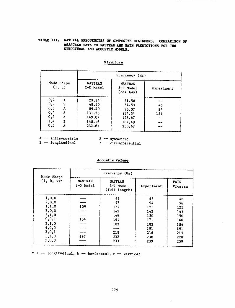
TABLE ][lI. NATURAL FREQUENCIES OF COMPOSITE CYLINDERS. COMPARISON OF
__.ASURED DATA TO NASTRAN AND PAIN PREDICTIONS FOR THESTRUCTURAL AND ACOUSTIC MODELS.
Structure
Mode Shape
(l, c)
0,2 A
0,2 S
0,3 A
0,4 S
0,4 A
1,4 S
0,5 A
NASTRAN
2-D Model
29.34
48.50
89.40
131.38
149.07
148.16232.81
Frequency (Hz)
NASTRAN
3-D Model
(one bay)
31.58
54.53
96.07
134.34156.67
162.40250.67
Experiment
46
84
121
A _ antisymmetric
i -- longitudinal
S _ symmetricc -- circumferential
Acoustic Voltme
Frequency (Hz)
Mode Shape ....
(1, h, v)* NASTRAN NASTRAN PAIN
2-D Model 3-D Model Experiment Program
(full length)
1,0,0
2,0,0
I,I,0
3,0,0
2,1,0
0,0,I
3,1,0
4,0,0
3,0,1
1,2,0
5,0,0
u_
109
154
_w
197
49
97
121
142
148
161
183
218
232
233
47
94
121
143
150
171
183
191
216
230
239
48
96
125
143
150
160
184
191
215
228
239
* I -- longitudinal, h -- horizontal, v m vertical
279

(I, i) 239.57Hz
(2, I) 375.07Hz
(0, O, 3) 48.73 Hz
(2, 0) 178.64Hz
(I, i) 313.11Hz
(I, I, 0) 116.20Hz
(i, O, i) 166.58Hz (3, i, 0) 164.90Hz
Figure I. Examplesof acoustic modeshapesfor somesimple geometriespredicted with NASTRANusing a structural-acoustic analogy.
280

ID FIR,ACOlIME 100APP OISPS_L B,O
ALTER 100_I00 $
MTRXIN CASEXX,MAIPDOL,EQDYN,_TFPDqL/K2DPP_,B2PP/LUSETD/S,_
NOKZDPPIS,N,NOB2PP $
ALTER 100 $
LABEL LBLSAV $
TRNSP KZOPP/XMP $
bOO XMPtlM2OPPIC,Y_ALPHA=(-1.BI-15,O.O)/CtY,BETA=(O.O,O.O')
PARAM //C_N_NDD/VtN_NOH2DPP=I $:ENDALTER
CEND
IO FIR,ACO
TIME 100
APP DISP
SOL ii,0
ALTER 91,91 $
MTRXIN CASEXX,MATPODLtEQDYNe_TFPOOL/K2PPtgB2PP/LUSETD/SpNj
NOK2PP/StNtNOB2DP $ALTER 91 $
LABEL LBLSAV $
TR.NSP K2PP/XMP $
AOD XMPg/M2PP/C_Y,ALPHA=(-I.BI-IS,O.O)/C,Y_BETA=(O.O_O.O)
PARAM I/C,NtNOP/VtN,NOMZPP=I $ENDALTER
%END
Figure 2. ALTER sequence for solution of fluid-structure interaction.
Direct approach - COSMIC/NASTRAN solution 8. Modal approach -COSMIC/NASTRAN solution Ii.
281

Structuraldisplacement (mm)
10,000 I
1000
10 I i i _ i
J\! J
5 10 15 20 25 30
Frequency, Hz
Structuraldisplacement (mm)
10,000
1000
100
I I I t t10 J5 10 15 20 25 30
Frequency, Hz
Figure 3. Frequency response function of structural point located
directly under load. (a) NASTRAN direct approach,
(b) NASTRAN modal approach.
282

Sound
pressurelevel,
dB 134
114 B
a
Figure 4.
94
74
54 I | I I ' J
5 10 15 20 25 30
Frequency, Hz
C
Sound
pressurelevel,dB 134
114, B
b 94
74 _ C
545 10 15 20 25 30 •
Frequency, Hz
Acoustic frequency response: A = acoustic - structure
interface, B = half-radius, C = center, (a) NASTRAN
direct approach, (b) NASTRAN modal approach
283

/
I'!
/I
l!
\\
0.62 Hz
\
\
l I
F
3.26 Hz
," I'\ t / - _ \'
,/ \',, _.' \,I
\ "k // /',
5.0 Hz 20.0 Hz
Figure 5. Dynamic shapes of structure and acoustic space predicted with NASTRAN
using 2D model and fluid-structure interaction equations. Frequency
indicated is for structure.
284

\ JMode 2S 48.5 Hz
Mode 3A 89.4 Hz
(0, i) 154 Hz
(2, 0) 197 Hz
(I,049 Hz
Mode 2S 54.53 Hz
Mode 3A 96.07 Hz
(I,i,0)
121Hz
Figure 6. NASTRAN predictions of structural and acoustic mode shapes
of composite cylinder based on two- and three-dimensional
models.285