n s sodha, former executive director, powergrid · pdf filemonitoring of all oil parameter...
TRANSCRIPT

N S Sodha,
Former Executive Director,
POWERGRID Corpn, Gurgaon

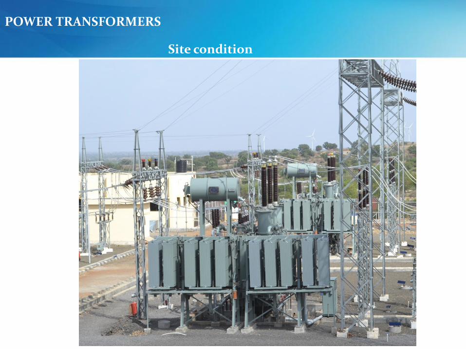
POWER TRANSFORMERS
Factory condition
POWER TRANSFORMERS
Site condition

POWER TRANSFORMER FAULTS
Faults in a Transformer
1. Internal Faults2. External faults3. Auxiliary Faults

Transformer failure rates

DEVELOPMENT AND RESULTS OF A WORLDWIDE TRANSFORMER RELIABILITY SURVEY
S. Tenbohlen, J. Jagers, G. Bastos, B. Desai, B. Diggin, J. Fuhr, J. Gebauer, M. Kruger, J. Lapworth, P. Manski, A. Mikulecky, P. Muller, C. Rajotte, T.
Sakai, Y. Shirasaka, F. Vahidi
On behalf of CIGRE WG A2.37
Acknowledgement
Presented at CIGRE SC A2 COLLOQUIUM 2015 during Sep 20-25, 2015 at Shanghai, China
6

IntroductionWG A2.37 was formed with an objective of
Review of all existing surveys and study different practice
Conduct new International survey
Compiling and analysis of collected data
Interpreting the results
Calculation of failure rates
Classification of failure locations
Failure causes and modes
7

Failure definition Only transformers/reactors > 60 kV considered
Major failure
Situation requires removal from service > 7 days
Involves major repair – factory or repair bay
Opening of transformer, tap changer or exchange of bushing
< 7 days, but with extensive oil processing
8

Failure Rates
9

Failure locations > 100 kVSubstation Transformers (536 Failures)
10

Failure Locations > 100kVGSUs (127 Failures)
11

Failure Locations > 100kVManufactured before 1980 (333 Failures)
12

Failure Mode all Voltage class964 Failures (SS and GSU)
13
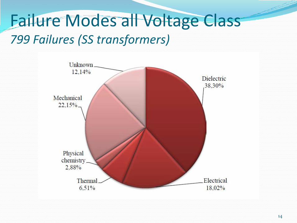
Failure Modes all Voltage Class799 Failures (SS transformers)
14

Failure Mode analysis according to Voltage Class
15

Failure Cause 964 Failures
16

External effect Analysis
76.5 % of failures did not result into any external effects
7.1 % failures resulted in Fire
5.1 % failures are related with explosions or blasts
17

External Failure effects964 Failures
18

Failures with Fire or explosions(126 Failures)
19

External effects of Bushing failures115 Failures
20

Action taken analysis964 Failures
21

Failure location analysisof 242 scrapped transformers
22

Failure location analysis of 465 repaired transformers
23

CIGRE WG-ConclusionsOverall failure rates remained < 1 %
GSU failure rate marginally higher than SS X’mer failure rate - difference is < 0.5%
GSU (300-500kV)failure rate exceeded 1%
Winding, tap changer, bushings followed by lead exits – major contributors
24
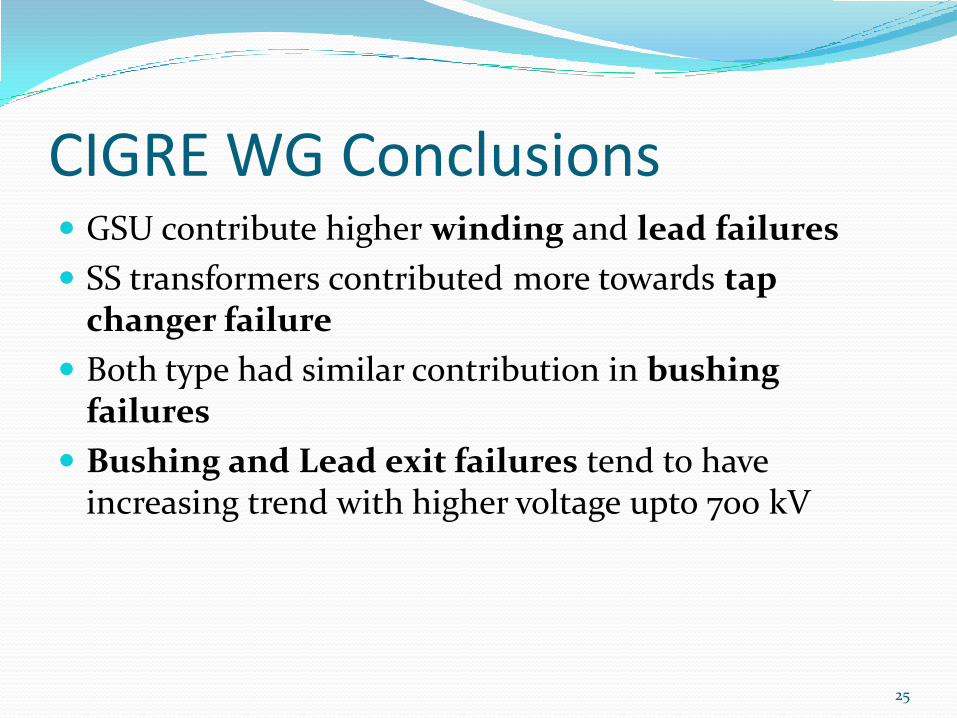
CIGRE WG Conclusions GSU contribute higher winding and lead failures
SS transformers contributed more towards tap changer failure
Both type had similar contribution in bushing failures
Bushing and Lead exit failures tend to have increasing trend with higher voltage upto 700 kV
25

CIGRE WG Conclusions Dielectric failures – highest contributors
Design and manufacturing, ageing and external short circuits - major contributors
Bushing failures most often result in fire and explosions
Large contributors being ‘unknown’, results should be treated with caution
26

POWERGRID, IndiaPower Transformer/Shunt Reactor Asset
Performance & Preventive Actions
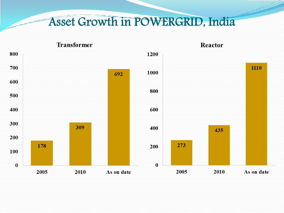
Asset Growth in POWERGRID, India

Growth of 765kV Transformers in POWERGRID, India
0
50
100
150
200
250
300
Till 2011 2012 2013 2014 As on date
Qu
an
tity
Period

Growth of 765kV Reactors in POWERGRID, India
0
100
200
300
400
500
600
Till 2011 2012 2013 2014 As on date
Qu
an
tity
Period

Failures of AC Transformers2011-12 2012-13 2013-14 2014-15 2015-16
Population 10 100 135 206 247
Failure - 1 - 1 2
% Failure - 0.1 0 0.49 0.809
2011-12 2012-13 2013-14 2014-15 2015-16
Population 10 147 218 436 507
Failure - - - 1 2
% Failure 0 0 0 0.23 0.395
Failures of Shunt Reactors

Transformer and Reactor FailuresFirst 765kV Transformer commissioned in the year 2007 and
first 765kV Reactor commissioned in 2007.
First failure of Transformer was encountered in 2013 and
first Reactor was encountered in the year 2015
So far, failure of 4 Nos. Transformer and 3 nos. Reactor were
encountered.
All of the failures were attributed due to failure of winding
unlike 400kV Transformers and Reactors where most of the
failures were due to bushing

POWERGRID’s Preventive Measures/Philosophy Each bank of 765kV Transformer and Reactors are having a dedicated hot
stand by spare
Charging of spare Transformer and Reactor on rotational basis in every 4
to 6 months
Each 765kV Transformers and Reactors are equipped with on line DGA
monitoring System, On line drying System FO temperature sensors &
Digital RTCC.
Commissioning of Controlled Switching Devices, On line DGA/ Dry out
System along with Transformers and Reactors and Validation and SCADA
Integration of Fiber Optic Temperature Sensors
Six Monthly Review of DGA and Oil Test results by Committee of
Expert.
Periodic review of AMP test results by Committee of Expert.
Monitoring of Bushing Tan delta before expiry of warrantee period

POWERGRID’s Preventive Measures/Philosophy
Monitoring of oil:
Norms for DGA Testing of oil :
Just after charging,
After 24 Hrs. of charging,
After one week of charging
15 days of charging
One month of charging.
On monthly basis till warrantee Period
Thereafter 2 monthly basis
Monitoring of all oil parameter tests (except oxidation stability) within six month of charging and thereafter yearly basis
Particle counts measurement before and within three months of charging.

Further Improvement:
Inclusion of UHF PD monitoring System and SelfDehydrating Breathers in TS.
SCADA integration of on line DGA monitoring System, Online drying System, FO temperature sensors are underprogress for remote monitoring.
Standardisation of Transformer and Reactor design for easeof maintenance
Inclusion of RIP bushings with polymer housing to avoidcatastrophic failure
Bushing and Transient voltage monitoring system
POWERGRID’s Preventive Measures/Philosophy

Water – the worst enemy of
a transformer...
A transformer with low moisture content is like a person in
good condition
A transformer can be used at high load without
risk for catastrophic failure.
A person can work hard without risk for heart attack
A wet transformer is like an overweight person in bad
condition
The transformer owner has to limit load to avoid bubbling
(may lead to catastrophic failure)
Moisture in insulation increases the rate of aging
The person can not run the marathon...
Water/moisture and (high) temperature will sooner or later kill
the transformer

How Water affects the transformer performance?
Loading capability
Limits the loading capability due to decreased
bubbling inception temperature
Dielectric strength
Decreases the dielectric strength of the oil and
decreasesPD inception voltage
Aging
High temperature and moisture will dramatically
accelerate aging that lowers the mechanical strength
of the cellulose insulation

Loading capability is limited by high moisture Moisture determines the
maximum loading/hot-spot
temperature for bubble
inception
Knowing moisture content
and oil quality allows for
correct decision on
maximum loading
Leave as-is
Dry-out/re-generate oil
Replace/Relocate
ScrapG. K. Frimpong et al, “Estimation of Moisture in
Cellulose and Oil Quality of Transformer
Insulation using Dielectric Response
Measurements”, Doble ClientConference,Paper 8M,2001.
Temperature limits from IEEE C57.91-1995

Life of a transformer –Moisture and aging During manufacturing, the cellulose insulation in the transformer is
carefully dried out before it is impregnated with oil
The moisture content in the solid insulation of a new transformer is
typically targeted to be < 0.5% by weight
As the transformer gets older, the moisture content will increase
Open-breathing transformers, typically around 0.2%/year
Sealed conservator transformers, typically around 0.05%/year
In an old and/or severely deteriorated transformer, the moisture
content can be > 4%
The aging process of the insulation is directly related to moisture
content

50
45
40
35
30
90 100 110 120 130 140
Winding Hot Spot
°C
rK 25
rof 20rota 15
cF
n 10gi
g A 5
0
80
aft
Paper
(IE
EE
)
IEEEKraft
0.5
%
W ater
1%
2%
4%3%
5%
Moisture accelerates aging
Left: Lars E. Lundgaard, Walter Hansen, Dag Linhjell, TerenceJ.
Painter, “Ageing of oil-impregnated paper in power
transformers”, IEEE PWRD, 2003
~2 years @3%
~12 years @1%

Where does the water comefrom?
Leaking gaskets and
faulty water traps may
expose the inside of the
transformer to moisture
humid air
Exposure to humid air
during site
installation/commissioni
ng
Exposure to humid
air during
maintenance
Normal aging of
cellulose produces
water
Insufficient drying
at manufacturing
Typical moisture content in
paper/pressboard:
New transformer: < 1%
Aged transformer: 2 - 4%
Normal increase of water content is typically 0.05-
0.2%/year

Interpretation of moisture content by various standards andpractices < 1% - “As new”
1-2% - “Dry”
2-3% - “Moderately wet”
3-4.5% - “Wet”
> 4.5% - “Excessively wet”
1)Original data in IEC60422, annexA, are presented as relative saturation in percentage. ”Dry”, ”Moderately wet”, ”Wet”
and ”Extremely wet” are recalculated to percent moisture in cellulose.
2)Original data in IEC60422 for new transformers is presented as percent moisture in cellulose
insulation.
3)Original data in CIGRE349 is by categories. “Good, “Fair”, “Probably wet” and “Wet” are relabeled to “Good/New”,
“Dry” and “Wet”.

Transformer drying –Methods/Examples
Two major techniques are used:
Drying the insulation by drying the oil – Field
Drying the insulation with heat and vacuum – Field and
factory
Drying the oil
Molecular sieves
Cellulose filters
Cold traps
Combined oil regeneration and degassing
Drying the insulation
Vacuum and heat
Pulsation drying through oil circulation
Hot oil spray drying
Low frequency heating
Vapour phase drying
A. Gruber, ”Online Treatment of Transformers and
Regeneration of Insulating Oil”, TechCon
AsiaPacific2009

TESTING OF POWER TRANSFORMERS
Tests on Transformer
Sweep frequency response analysis (SFRA)
SFRA test is carried out to obtain initial signature of
transformer sweep frequency response . The test connections , procedure and connections shall
be defined for repeatability. The test can be repeated after a major event
transportation, short circuit, periodic maintenance,earth quake etc.

TESTING OF POWER TRANSFORMERS
Tests on Transformer
Sweep frequency response analysis (SFRA)
Healthy HV &
LV winding
s

TESTING OF POWER TRANSFORMERS
Tests on Transformer
Sweep frequency response analysis (SFRA)
U-phase shorted
turn

TESTING OF POWER TRANSFORMERS
Tests on Transformer
Sweep frequency response analysis (SFRA)

Conclusions on moisture/waterMoisture is the worst enemy of the transformer!
Limits the loading capability
Accelerates the aging process
Decreases dielectric strength
The water/moisture in a transformer resides in the solid insulation, not in the oil
Dielectric Frequency Response Measurement is a great technique for moisture assessment as it measures: Moisture content in the cellulose insulation
Conductivity/dissipation factor of the insulatingoil
Power frequency tan delta/power factor, accurately temperature corrected to 20 C
reference temperature
Drying a power transformer can take from days to years depending on drying process & technology
Enhanced Reliability thru. Accessories Monitoring and Control
Major accessories are Bushings, OLTC,OCTC, Temperature indicators, oil preservation system and CTsBushings are High voltage bushings for HV Windings and high Current bushings for low voltage windings. HV Bushings are mainly OIP bushings. Now the trend is to go for Resin Impregnated Paper (RIP) Bushing.Polymer insulation instead of Porcelain for operational safety.OLTC have different current and voltage ratings. Most of OLTCs are high speed resistor type. There are OLTC mounted inside the tank and also outside the tankOCTC like OLTC have different voltage and current rating.OCTC are linear/reversing typeTrend is to go for Vacuum Type OLTC which has more contact life & less maintenance.

Comparison between mineral oil and Synthetic Ester& Natural EsterProperties Mineral Oil Synthetic Ester Natural Ester
Envirotemp FR3
Expansion coefficient (°C) 0.00075 0.00075 0.00075
Kinematic Viscosity at 40°C(mm2/s)
8-10 34 32-33
Specific Heat at 20/25°C (J/kg.K) 1860 2065 1880
Thermal conductivity at 20/25°C(W/m.K)
0.126 0.161 0.167
Pour point (°C)
in accordance with ISO 3016
-57 -60 to -57 -20 to -26
Breakdown voltage
after treatment (kV)
>70 >75 89
Dielectric
dissipation factor
<0.001 <0.03 <0.04
Permittivity 2.2 3.2 3.2
Reference Standard IEC-60296 IEC-61009 IEC-62770

RIP Condenser BushingRIP condenser bushing with Polymer (Silicon Rubber) Insulator
Fire Resistance & explosion proof
Plug in type up to 420kV

Enhanced Reliability thru. Accessories Monitoring and Control Oil preservation systems
Conservator with silicagel breather, air cell conservator ,N2sealed conservator, Dry Col breather
Thermometer
Thermal image type OTI and WTI. Fiber optic thermal sensors
Monitoring Device for oil, winding temperature, cooler, OLTC,bushing, oil ppm, gas, PD
Trend
Substation automation with control for system operationcomplying with IEC 61850communication protocol standard

Transformer Monitoring System

Assets Health Information flow

Fiber Optic Temperature SensorAccurate measurement of Winding temperature for protection & utilization of transformer

Energy Efficient transformer
IEC 60076-20 covers to choose a transformer with an appropriate level of energy efficiency , according to the loading & operating conditions.The total capital & the estimated lifetime operating and maintenance cost ( TCO = total cost of ownership) are also significant consideration in determining the most suitable transformer for the intended application.

Conclusion
In future, Power transformer will have to meet increasingly stringent environmental and safety requirement. Replacement of mineral oil by biodegradable natural/synthetic Ester oilEnergy efficient transformers as per IEC60076-20 Di-electrical design and appropriate analytical tool will need enhancement to support the next generation transformers such as HTS transformers, Flexible AC Transmission System (FACTs) and Phase Shifting Transformers.Factory capability assessment as per Cigre Guide TB530Design Review as per Cigre Guide line TB529

On Line DGATransformer faults detection inearly stageSafe & optimized utilization Prediction of ageing Fault classification from results Gases measured
HydrogenMethane Ethane EthyleneAcetylene Carbon monoxide Carbon dioxideOxygen
NitrogenWater

Future TransformersMobile transformers.Large capacity three phase transformer.Phase shifting transformer.Tapless transformer.Mobile test system.Green Transformer.Site assembled transformer.Energy efficient transormers
Figure showing compact 3 phase 930 MVA 550
kV GT
Figure showing Mobile power transformer and substation

Milestones in Indian Power Transformer Industry
333MVA, 1200kV ULTRA
HIGH VOLTAGE
POWER TRANSFORMER

Thank you for your Kind attention!