mz-one controller - inventer · mz-one ® controller • installation and operating instructions 2...
TRANSCRIPT

MZ-One
controller
Installation and Operating instructions

2
MZ-One® controller • Installation and operating instructions
Trademarks, copyrights and property rights
inVENTer®, MZ-One® and Clust-Air® are protected trademarks of inVENTer
GmbH.
The copyright of this document remains with the manufacturer.
Rights to all content and images: © inVENTer GmbH 2015-17.
All brand or product names used in this documentation are the property of their respective owners, and are hereby acknowled-ged.
Disclaimer of liability
This documentation is a translation of the german original in-
stallation instructions. After completion of the installation it must
be given to user (tenant, owner, property management, etc.).
The content of this documentation has been checked for compliance
with the described hardware and software. Nevertheless deviations
may still occur, therefore no guarantee of compliance can be provided.
This documentation describes the functionality of the standard scope.
The documentation does not purport to cover all details on all types of
the product and cannot cover every conceivable scenario for installation.
The illustrations in this document may difer slightly from the design of the product that you have purchased. The same
functionality is ensured despite any design deviations.
This documentation is updated regularly. Necessary cor-
rections and appropriate supplements are always includ-
ed in subsequent editions. You can ind the latest version at www.inventer.eu/downloads
Version 2.4

3
MZ-One® controller • Installation and operating instructions

4
MZ-One® controller • Installation and operating instructions
Table of contents
1 User and safety instructions .................................................................................................. 6
1.1 User instructions ............................................................................................................ 61.2 Safety instructions .......................................................................................................... 7
2 System overview ..................................................................................................................... 8
2.1 Layout ............................................................................................................................ 92.2 Function ......................................................................................................................... 11
3 Operation and display elements ............................................................................................ 15
3.1 Programming unit ........................................................................................................... 153.2 Output level display in the 7-day timer menu ................................................................. 16
4 Electrical connections ............................................................................................................ 17
4.1 Connection of MZ-One as base unit (example) ............................................................. 184.2 Interfaces and terminal assignments ............................................................................. 204.3 Wiring ............................................................................................................................. 224.4 Zone assignment on the Clust-Air module'e DIP switch ................................................ 22
5 Preparations prior to installation ........................................................................................... 24
5.1 Installation advices and installation sites ....................................................................... 245.2 Dimensions .................................................................................................................... 245.3 Dimensioned drawings ................................................................................................... 25
6 Installation and assembly ....................................................................................................... 27
6.1 Fitting the lush mounted box/plasterboard box ............................................................. 276.2 Connecting the power supply unit .................................................................................. 286.3 Laying cables ................................................................................................................. 286.4 Installing the programming unit and irst Clust-Air module............................................. 306.5 Installing additional Clust-Air modules ........................................................................... 356.6 Installing the Humidity-temperature sensor.................................................................... 38
7 Commissioning ........................................................................................................................ 40
7.1 Functional test ................................................................................................................ 407.2 Connection ..................................................................................................................... 42

5
MZ-One® controller • Installation and operating instructions
8 Operation .................................................................................................................................. 43
8.1 Menu structure ............................................................................................................... 438.2 Main screen.................................................................................................................... 448.3 Gaining manual control .................................................................................................. 458.4 Main Zone menu ............................................................................................................ 468.5 Main settings menu ........................................................................................................ 478.6 Calling up the main Settings menu ................................................................................ 478.7 Programming the 7-day timer......................................................................................... 488.8 Setting the ilter change interval ..................................................................................... 528.9 Conirming ilter change ................................................................................................. 538.10 Setting the language ...................................................................................................... 548.11 Setting the date and time ............................................................................................... 548.12 Enabling/ disabling the interface .................................................................................... 578.13 Adjusting settings on the display unit ............................................................................. 588.14 Deining output levels ..................................................................................................... 608.15 Deining limits for the temperature-humidity sensor ....................................................... 618.16 Activating/ deactivating the temperatre-humidity sensor ............................................... 628.17 Calling up information .................................................................................................... 638.18 Viewing hours run .......................................................................................................... 648.19 Returning to factory settings .......................................................................................... 648.20 Carrying out a functional test ......................................................................................... 658.21 Manually enabling/disabling the dehumidiication mode (optional) ................................ 65
9 Servicing and maintenance .................................................................................................... 66
10 Speciication ............................................................................................................................ 67
11 Standard delivery .................................................................................................................... 68
12 Accessories and spare parts .................................................................................................. 68
13 Troubleshooting and disposal ............................................................................................... 69
14 Warranty and Guarantee ......................................................................................................... 70
15 Service ...................................................................................................................................... 70
16 Company details ...................................................................................................................... 71

6
USER AND SAFETY INSTRUCTIONS
MZ-One® controller • Installation and operating instructions
1 User and safety instructions
1.1 User instructions
Understanding the safety instructions
The safety instructions in these installation and operating instructions are set out in a standard way and are identiied with a symbol to the left of the instruction. A signal word above the text indicates the level of risk involved. Where several diferent hazard levels coincide, the warning notice for the highest level is always used.
SIGNAL WORDType and source of hazard.
Possible consequences of the hazard! ► Action to be taken to aoid the hazard.
The signal word indicates the level of danger and severity of injury that arise if the instructions and safety information are not observed:
DANGER indicates: Immediate risk of serious personal injury or death.
CAUTION indicates: Immediate or possible risk of slight/moderate personal injury.
Further symbols used in this documentation
In addition to the safety instructions the following symbols are used:
The signal word NOTICE indicates immediate or possible risk of material losses due to an undesirable event or state.
The TIP symbol provides practical and useful handling information for using the MZ-One controller.
The lash symbol in graphics is an additional indication and reminder for DANGER. Make sure the power supply is disconnected before continuing with this step.
Indicates necessary tools and materials for the following steps.
► Action required: this requires the user to perform a speciic action. Check the results: this requires you to check the results of the action you have performed. Green arrow: speciies the location of the necessary action. Ellipse: Shows where an information is displayed or changed (section 8: Operation). Book: refers to another section in this documentation.Grey text in italics refers to the installation of optional elements.
Graphics in section 6 show the interior wall. Graphics in sections 7 and 8 show MZ-One's display.

7
USER AND SAFETY INSTRUCTIONS
MZ-One® controller • Installation and operating instructions
1.2 Safety instructions
Before working on the controller, read the safety instructions carefully and make sure you under-stand them. Observe all instructions on installation, operation and maintenance of the MZ-One controller listed in this section. Also observe any safety instructions that precede the operating instructions. Failure to observe safety instructions can cause personal injury and material losses.
Intended use
The MZ-One controller is an electronic control unit for inVENTer® decentralised mechanical ventilation units with heat recovery.
When installing the controller, observe the applicable building codes, ire safety regulations and accident prevention regulations of the Employer's Liability Insurance Association [Germany] or local equivalent.Use the controller only in accordance with the applications described in this documentation and only in combination with the components recommended, approved and speciied by inVENTer GmbH in this documentation. Changes and modiications to the controller are not permitted. Trouble-free and safe operation of the controller can be ensured only provided it is transported, stored and assembled correctly and operated and maintained with care. This documentation is considered part of the controller and must be kept permanently available.
The installation and operating instructions apply only in conjunction with, and are supplemen-tary to, the installation and operating instructions of the iV-Smart, iV-Smart Corner, iV-Smart Ohio, iV14R, iV14R-Corner, iV14R-Ohio, iV14R-Sylt, iV14V, iV14V-Ohio, iV14V-Corner, iV-Twin and iV25 ventilation units, and of the USTS vent system. All of the legal notes contained in the installation and operating instructions are also fully applicable to this document.
DANGER: Observe the speciications of protection class II during laying and connecting of po-wer cables. Lay mains and control cables separately and whilst not live. Ensure that the mains supply (Voltage, Frequency, and Phase) complies with the rating label. Before starting any work on electrical installations, disconnect every unit concerned from the power supply. Attach all ventilation units and controller at the same circuit breaker.
CAUTION: Operation should not be carried out by children or persons with restricted physical, sensory or mental capabilities or who lack of experience and/or knowledge to do so. Children must be supervised to make sure they do not play with the appliance.
Unauthorised use results in the loss of any claim of liability.
Unauthorised use
The controller is intended solely for controlling the ventilation units mentioned in section intend-ed use. Any other use is expressly forbidden.
Qualiied personnel
The controller complies with the applicable technical safety requirements and standards for electrical equipment. It may only be set up and operated in conjunction with this documentation. Installation, electrical connection and commissioning of the controller may only be performed by qualiied personnel. Qualiied personnel within the meaning of the safety notices in this docu-mentation are persons who are authorised to install, put it into operation and identify equipment, systems and circuits in accordance with established safety procedures.

8
SYSTEM OVERVIEW
MZ-One® controller • Installation and operating instructions
2 System overview
The MZ-One controller is an electronic control unit for inVENTer® decentralised mechanical ventilation units with heat recovery. The MZ-One controller can be used to control up to:
• 16 iV-Smart ventilation units with up to 4 ventilation units per Clust-Air module• 16 iV14 ventilation units with up to 4 ventilation units per Clust-Air module• 8 iV25 ventilation units with up to 2 ventilation units per Clust-Air module• 8 iV-Twin ventilation units with up to 2 ventilation units per Clust-Air module
It provides excellent Clust-Air® technology (multi-zone control), easy installation, an operating concept via touch, and its versatility of use.
The MZ-One controller consists of an MZ-One programming unit and between one and four Clust-Air modules. Each Clust-Air module controls the ventilation units of its designated area (zone) within a residential unit. Thus, the MZ-One controller provides separate ventilation for up to four diferent areas within the residential unit. For each deined zone, the operating mode and output level can be set by means of the 7-day timer or manually.
The controller can be used either as a base module or with additional sensors connected. An external interface allows the connection of a potential-free switching contact or integration into an existing home automation system via an analogue input.
The connected ventilation devices can be controlled in the following modes:
• Heat recovery • Dehumidiication• Ventilation • Sleep timer
The software is available in two languages.
Optionally, a CO2 sensor can be purchased as an accessory from inVENTer GmbH.
Features
• Intelligent Clust-Air® technology provides control of up to four diferent areas (zones) within one residential unit
• Visually discreet due to lush-mounted modules• Backlit display unit• Easy operation by means of touch-sensitive keys (navigation arrows)• Control of the ventilation devices in four operating modes:
Heat recovery, Ventilation, Dehumidiication and Sleep timer• Output levels of the fans assigned to a zone speciied individually• Integral temperature-humidity sensor to switch the operating mode automatically subject to
the relative humidity indoors• Interface for external input or connection to an existing home automation system• Connections for additional sensors: CO
2 sensor (available as accessory), VOC sensor1) or
pressure switch can be connected via loating input• Hours run meter• Filter change indicator

1 Glass panel2 Casing,
consists of base plate and cover3 Display unit4 User interface with touch-sensitive keys
(navigation arrows)
ON
1 2
1 Terminal for temperature-humidity sensor, 4-pole
2 External interface, 2-pole3 Terminal for control BUS, 4-pole4 Terminal for fan BUS, 3-pole5 DIP switch
9
SYSTEM OVERVIEW
MZ-One® controller • Installation and operating instructions
2.1 Layout
MZ-One programming unit
Fig. 1: Front view of MZ-One controller
The MZ-One programming unit serves as entry and display surface for the user.
Clust-Air module CAM15
Fig. 2: Front view Clust-Air module
The Clust-Air module contains the PCB for the zone being controlled. The module is installed in a lush mounted box and connected. After installation, we recommend using a switch style cover or papering over the lush mounted box.
Using the Clust-Air modules it is possible to split the home into separate ventilation zones. Each Clust-Air module is assigned to one ventilation zone. It is installed within its own ventilation zone and can be controlled separately. A Clust-Air module provides control of up to four inVENTer® ventilation units, alignment of one combined temperature-humidity sensor and align-ment of one additional external sensor (digital or analogue).
1
23
4
5
3
2
1
4

10
SYSTEM OVERVIEW
MZ-One® controller • Installation and operating instructions
Humidity-temperature sensor FTS31
Fig. 3: Humidity-temperature sensor FTS31
The humidity-temperature sensor is delivered preassembled in a corresponding casing. It is mounted in the room's air low and connected to the Clust-Air module controlling the assi-gned zone. The humidity-temperature sensor integrated into each Clust-Air module continuously captures the relative humidity inside the zone. Depending on the relative humidity, the controller is thus able to switch the dehumidiication mode on and of automatically within speciied limits. This achieves a healthy room climate that meets your needs without the need for manual interventi-on. Observe the correct positioning of the humidity-temperature sensor inside the room's air low. Inadequate circulation of the sensor causes wrong measurement. When installing the hygrost-at, make sure that the ventilation slots are at the top and bottom to ensure optimum airlow to the hygrostat.
1
1 Casing, consists of base plate and cover, including preassembled temperature-humidity sensor

11
SYSTEM OVERVIEW
MZ-One® controller • Installation and operating instructions
2.2 Function
Thanks to its unique Clust-Air® technology (multi-zone control), the MZ-One controller is capab-le of controlling up to four zones within a single residential unit. The diferent living areas can each be controlled using the MZ-One controller either by means of a 7-day timer or manually. The controller can be used either as a base module (without connected interface) or with additi-onal sensors connected.
MZ-One controller without connected interface
Heat recovery mode (HR):
The ventilation system works on the regenerator principle. An integral thermal accumulator is charged with heating energy from the warm indoor air as it is discharged outside (extract air). The fan changes its rotational direction every 70 seconds. When the fan changes direction, it releases the stored heating energy to the incoming outdoor air (supply air). This is the standard operating mode during the heating season. It is equally recommended for summer use, since it signiicantly reduces heat input during ventilation.
Ventilation mode (V):
The ventilation device fan operates without changing its rotational direction. This operating mode is recommended for cooling the room on summer nights.
Dehumidiication mode (DH):The dehumidiication mode cannot be selected individually. If the relative humidity in the interior exceeds the preset limit, the MZ-One controller switches all ventilation systems connected to the Clust-Air module in the relevant zone to dehumidiication. High moisture levels in the air are thus removed from the room quickly. The ventilation unit fan operates without changing its rota-tional direction. Once the relative humidity falls below the limit, the MZ-One controller reverts to its previously set operating mode.
Sleep timer (sleep) and OFF:The ventilation device fan is switched of in the mode.
Deining the output level of the controller:On the MZ-One controller, three output levels can be deined and stored for the heat recovery and ventilation modes, and one output level for the dehumidiication mode. These can be altered individually to output levels of between 25 % and 100 %. The new setting takes efect immediately, so it can be changed simply for reasons of acoustic tolerability.
Other settings:
In addition, the brightness and ON-duration of the display unit can be set. This setting similarly takes immediate efect.

12
SYSTEM OVERVIEW
MZ-One® controller • Installation and operating instructions
MZ-One controller with connected interface (advanced features)
The external interface is bifunctional. It can be connected to a loating contact or used as an analogue input for integrating the ventilation system into an existing home automation system. An interface is to be found on each Clust-Air module so that one external interface can be used per Clust-Air module.
Connecting the external interface changes the functionality of your controller as follows:
A. Interface as external contact
Floating ON/OFF switch (N/O)
Select the input ext. switch for the relevant zone under settings in the main menu ( 8.5: Operation ‒ Main menu settings) when connecting an external ON/OFF switch to the Clust-Air module ( 8.12).
The ventilation system can be switched manually to dehumidiication if the external interface is used to connect a loating ON/OFF switch. The dehumidiication mode is deactivated by turning it of at the switch or through the 7-day timer function:
Mode/ function Turning the switch on Turning the switch of
Dehumidiication Switches all ventilation devices on the Clust-Air module to dehumidiication mode.
Switches all ventilation devices on the Clust-Air module back to their previously set operating mode.
External sensors
The sensor used must have a potential-free relay contact (NOC).
The connection of a pressure monitor is necessary in rooms with air-ventilated ireplaces. Please consult a chimney sweep/construction planner about this. If the interface is used for a pressure switch, the air pressure in the interior is measured contin-uously. Once the air pressure exceeds the safety threshold, the sensor reacts and turns of all ventilation devices connected to the programming unit. This function remains active until the air pressure drops back to below the safety limit.
If the external interface is used to connect a CO2 sensor, the CO
2 content in the interior is
measured continuously. A CO2 sensor is optionally available as accessory.
If the external interface is used to connect a VOC sensor, the composition of the air and the resulting air quality are measured continuously.

13
SYSTEM OVERVIEW
MZ-One® controller • Installation and operating instructions
SensorInput
( 8.12)Exceed of limit value Grenzwertunterschreitung
CO2 sensor ext. switch
Switches all ventilation units on the Clust-Air module to dehumidiication mode.
Switches all ventilation de-vices back to their previously set operating mode.
VOC sensor ext. switch Switches all ventilation units on the Clust-Air module to dehumidiication mode.
Switches all ventilation de-vices back to their previously set operating mode.
Pressure monitor
irepl. sw.Switches all fans connected to the MZ-One controller OFF.
Switches all fans connected to the MZ-One controller to their previously set operating mode.
B. Interface as analogue input
If the interface is used as an analogue input, the ventilation system can be integrated into an existing home automation system. To do so, a predeined voltage level is set in the home automation control unit, depending on the desired function. The control voltage should have a resolution of 10 bits.
TIP: it is not possible to connect a potential-free switch and an analogue input simultaneously on a Clust-Air module. A connected analogue input always has priority over a potential-free switching contact.
When connecting an analogue input to the Clust-Air module, under Settings in the main menu the input analogue must be selected for the relevant zone ( 8.12). Subject to control voltage, the following eight functions are available:
Mode Control voltage
Manual control 0.00 V ≤ U ≤ 0.50 V
Sleep timer 1.00 V ≤ U ≤ 1.50 V
Heat recovery, output level 1 2.00 V ≤ U ≤ 2.50 V
Heat recovery, output levele 2 3.00 V ≤ U ≤ 3.50 V
Heat recovery, output level 3 4.00 V ≤ U ≤ 4.50 V
Ventilation, output level 1 6.00 V ≤ U ≤ 6.50 V
Ventilation, output level 2 7.00 V ≤ U ≤ 7.50 V
Ventilation, output level 3 8.00 V ≤ U ≤ 8.50 V
C. Disabling interface
If it is not being used, the interface on the Clust-Air module can be disabled under Settings in the main menu ( 8.12).
14
SYSTEM OVERVIEW
MZ-One® controller • Installation and operating instructions
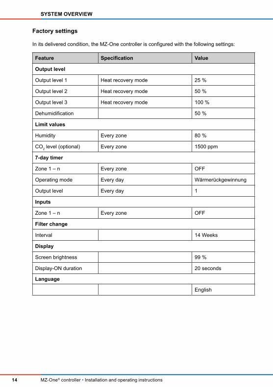
Factory settings
In its delivered condition, the MZ-One controller is conigured with the following settings:
Feature Speciication Value
Output level
Output level 1 Heat recovery mode 25 %
Output level 2 Heat recovery mode 50 %
Output level 3 Heat recovery mode 100 %
Dehumidiication 50 %
Limit values
Humidity Every zone 80 %
CO2 level (optional) Every zone 1500 ppm
7-day timer
Zone 1 – n Every zone OFF
Operating mode Every day Wärmerückgewinnung
Output level Every day 1
Inputs
Zone 1 – n Every zone OFF
Filter change
Interval 14 Weeks
Display
Screen brightness 99 %
Display-ON duration 20 seconds
Language
English

15
OPERATION AND DISPLAY ELEMENTS
MZ-One® controller • Installation and operating instructions
3 Operation and display elements
3.1 Programming unit
Fig. 4: Front: Operation and display elements
Display unit
The MZ-One controller display unit is located in the upper part of the programming unit. It is a backlit liquid crystal display. It comprises four lines, each of 20 characters, and displays func-tions and parameters.
After 20 seconds without operation the backlight fades automatically, so that during no operati-on takes place no disturbing light occurs.
Navigation arrows
The 4 navigation arrows (grey coloured in ig. 4) are located in the bottom part on the controller's programming unit are touch-sensitive keys. By touching any key, the display unit is activated and the main screen appears, and the controller can be operated.
The navigation arrows allow:
• navigating the menu,• selecting functions from the menu list,• conirming and changing parameters in the settings menu.
1 Display unit, main screen is shown in ig. 4
2 User interface with capacitive touch-keys Navigation arrow Navigation arrow Navigation arrow Navigation arrow
inVENTer
MZ-0ne
01.06.2015 12:42
1
2

16
OPERATION AND DISPLAY ELEMENTS
MZ-One® controller • Installation and operating instructions
3.2 Output level display in the 7-day timer menu
The submenu 7-day timer contains a display line for the currently set output levels of the zone. It serves as a guide when programming the 7-day timer.
You will ind the display line located in the fourth line of the display, if the submenu 7-day timer is active for programming. The display line is updated immediately after an input. This makes it easy to check whether your input is valid.
Fig. 5: 24-hours display line for currently set output levels of the fan
The display line consists of 12 bars. Each bar represents a 2-hours interval, beginning with the time period 0 – 2 o'clock (left bar), ascending in steps of two hours. The last bar (right bar) represents the time period 22 – 24 o'clock.
The height of the bar indicates the output level at the displayed time period, e. g. from 0 – 2 o'clock (left bar) all ventilation devices connected are set to output level 3, from 2 – 4 o'clock all ventilation devices connected are set to output level 2, and further on.
1 24-hours display2 Bar output level 33 Bar output level 2
4 Bar output level 15 Marking for sleep timer
(no bar)
So 00 - 02 h
WRG
Le: 1
3 245

17
ELECTRICAL CONNECTIONS
MZ-One® controller • Installation and operating instructions
4 Electrical connections
DANGERExposed electrical components.
Electric shock and injury due to live components (230V, 50Hz)! ► Before working on electrical installations, disconnect all afected equipment from the power supply. ► Observe the requirements for protection class II when laying the power supply cable. Do not lay or connect live cables.
► Lay the fan-BUS and power cables separately. ► The installation and connection must only be performed by qualiied and trained personnel.
NOTEInsuicient wire cross-section.Excessive voltage drop and/or contact cannot be guaranteed!
► Only use the following cable cross-sections: Fan BUS: Min. 0.75 mm² Power cable: 1.5 mm² Control BUS: 0.25 – 0.5 mm²
TIP:Connect the Clust-Air modules sequentially (one after the other). Ensure suicient clearance for the cables. Observe the maximum distances (maximum cable lengths). Terminate the last connected Clust-Air module with a terminator, 120 Ω.
Maximum cable lengths
Control BUS (cable J-Y(ST)Y-2x2x0.8):
Programming unit and last connected Clust-Air module: Max. 200 m Fan BUS (cable LiYY3x0.75):
1. Star-shaped connection of fans to the Clust-Air module:
• between Clust-Air module and iV-Smart/iV14 ventilation device: Max. 33 m• between Clust-Air module and iV25/iV-Twin ventilation device: Max. 20 m
2. Sequential connection of fans to the Clust-Air module, maximum distance between Clust-Air module and last connected ventilation device:
• Clust-Air module with 4x iV-Smart/iV14 ventilation units : Max. 10 m• Clust-Air module with 2x iV-Smart/iV14 ventilation units: Max. 20 m• Clust-Air module with 2x iV25/iV-Twin ventilation units: Max. 10 m
Cable of humidity and temperature sensor (cable J-Y(ST)Y-2x2x0.8)
• between Clust-Air module, and humidity and temperature sensor: Max. 15 m

III
III
III
AC
DC
3
3
3
4
4
4
4
3
4
4
4
4
4
I
I
II
II
IX VIII VII VI
5 6
4
3
2
1
4
3
2
1
4
3
2
1
4
3
2
1
4
3
2
1
4
3
2
1
4
3
2
1
4
3
2
1
5 6
5 6
5 6
VIVIII VIVIII
III
IVV IIIV IVIIIV IV
III
IVV
III
IVV
III
IVV
VI VII VIII IX
VI VII VIII IX
VI VII VIII IX
VI VII VIII IX
VI VII VIII IX
L
PE
N
7
8
3 3
6
7
6
7
6
7
6
3121
4
4
4
4
9
01
01
01
01
5
VIV VIVIII IIIV IVIIIV IV3
5
3
VIV VIVIII IIIV IVIIIV IV3
5
3
VIV VIVIII IIIV IVIIIV IV3
5
3
11
11
11
2
1
11
18
ELECTRICAL CONNECTIONS
MZ-One® controller • Installation and operating instructions
4.1 Connection of MZ-One as base unit (example)
Fan BUS: Kabel LiYY3x0.75 / maximum cable length: 10 m (sequentially) 1)
wire: 2x1.5
Con
trol B
US:
cab
le J
-Y(S
T)Y-
2x2x
0.8
/ max
imum
cab
le le
ngth
: 200
m
Cable J-Y(ST)Y-2x2x0.8 / maximum cable length: 15 m
Fig. 6: Example of connection: MZ-One controller
TIP: For possible connections of the fans and the maximum cable lengths see 4: Electrical connections ‒ maximum cable lengths, page 17.
1) Maximum cable length up to 33 m when connecting the fans star-shaped.

19
ELECTRICAL CONNECTIONS
MZ-One® controller • Installation and operating instructions
Components
Power cable
N Neutral conductor BluePE Protective earth Green/yellow L Phase Brown I Controller operating voltage (+) Red II Controller operating voltage (–) Blue
Fan BUS (cable: LiYY3x0.75 – max. 33 m when connecting star shaped)
III Supply air (–) White IV Operating voltage (+) Green V Extract air (–) Brown
Control BUS between Clust-Air modules (cable: J-Y(ST)Y-2x2x0.8 – max. 200 m)
VI Clust-Air module power supply + 24 V Red VII Data cable A A Yellow VIII Data cable B B White IX Ground GND Black
Humidity-temperature sensor (cable: J-Y(ST)Y-2x2x0.8 – max. 15 m)
1 Supply voltage + 5 V Red 2 Data input DATA Yellow 3 Not assigned – White 4 Ground GND Black
External interface (Floating contact or analogue control cable 0 – 10 V)
5 Contact 1 Sk1 Analogue input (–) 6 Contact 2 Sk2 Analogue input (+)
1 PCB on the back side of the MZ-One programming unit
2 Connector for control BUS, 4-pole3 Connector for fan BUS, 3-pole4 Fan BUS, 3-wire5 Fans 1 – 4 per Clust-Air module6 Fan BUS connector, 3-pole7 Clust-Air module8 Terminator control BUS, 120 Ω
9 Control BUS, 4-wire10 Temperature-humidity sensor,
preassembled11 External interface12 Control panel13 MZ-One power supply unit
Input: 230 V, 50 Hz Output: DC 24 V, 2-pole

12
1 2 3 4
1
2
3
4321 4
321
ON
1 2
20
ELECTRICAL CONNECTIONS
MZ-One® controller • Installation and operating instructions
4.2 Interfaces and terminal assignments
MZ-One power supply unit
Fig. 7: MZ-One power supply unit interfaces
Rear side of MZ-One programming unit
Fig. 8: MZ-One programming unit interfaces
Clust-Air module / Humidity-temperature sensor
Fig. 9: Clust-Air module/ Humidity-temperature sensor interfaces
1 MZ-One power supply unit2 Power supply terminal3 Controller operating voltage4 LED
1 USB interface (For factory service settings/coniguration)
2 Connector for control BUS3 Controller operating voltage
Clust-Air module Humidity-temperature sensor
4 3 2 156
DC 24 V AC 230 V
4321
1 2
DC 24 V
1 Clust-Air module connector2 Humidity-temperature sensor,
preassembled3 Humidity-temperature sensor terminal
4 External interface5 Control BUS connector6 Fan BUS connector7 DIP switch
1
23
4
3
1
2
1
3
4
2
5
6
7

21
ELECTRICAL CONNECTIONS
MZ-One® controller • Installation and operating instructions
Terminal assignments
Notice for the Clust-Air module: The terminals are, depending on the terminal, a mixture of screw terminals (fan BUS and external interface) and spring-loaded terminals (control BUS and humidity-temperature sensor). The screw terminals have a connection capacity of up to 1.5 mm². Use braided wires with collared ferrules in screw-terminals. The spring-loaded terminals have a connection capacity of 0.1 to 0.5 mm². They are suitable for solid and stranded wires. The use of wire ferrules is not necessary. If wire ferrules are used, they must increase the cross-section (their material thickness is thereby not included).
TIP: The terminal assignments in the following table correspond with the connectors of the igures in section 4.2, page 20.
Connector Terminal Designation Meaning
Switching power supply unit
MZ-One power supply unit:power supply terminal
1 AC/L Phase
2 AC/N Neutral conductor
MZ-One power supply unit:operating voltage
3, 4 + 24 V Operating voltage programming unit5, 6 GND (‒)
Rear side of MZ-One programming unit
MZ-One programming unit:operating voltage
1 GND (‒) Operating voltage programming unit2 + 24 V
Control BUS connector, 4-pole, spring-loaded terminal
1 GND Ground
2 B Data cable B
3 A Data cable A
4 +24 V Supply voltage
Clust-Air module
Fan BUS connector, 3-pole, screw terminal 1.5 mm²
1 Lü1 Supply air
2 Ub+ Operating voltage
3 Lü2 Extract air
Humidity-temperature sensor, 4-pole, spring-loaded terminal
1 + 5 V Supply voltage
2 DATA Data cable
3 ‒ Not assigned
4 GND Ground
External interface,screw terminal 1.5 mm²
1 Sk1 Contact 1, analogue (‒)
2 Sk2 Contact 2, analogue (+)
Control BUS connector, 4-pole, spring-loaded terminal
1 GND Ground
2 A Data cable B
3 B Data cable A
4 + 24 V Clust-Air module operating voltage

ON
1 2
+ 24 VGND (‒)
22
ELECTRICAL CONNECTIONS
MZ-One® controller • Installation and operating instructions
4.3 Wiring
Connecting the ear side of MZ-One programming unit and the Clust-air module
1 Rear side of MZ-One programming unit2 Humidity-temperature sensor,
preassembled
3 Clust-Air module4 Connecting clamps5 Reversible fan
Lü1
Lü2
Ub+
Sk1Sk2
GND
+ 5 VDATA
GND + 24 V B A
Lü1
Ub+
Lü2
24
GND + 24 V B A
1
3
5
4.4 Zone assignment on the Clust-Air module'e DIP switch
The fans must be allocated to the four diferent zones according to your ventilation concept.
One Clust-Air module controls one speciic zone (all ventilation devices connected to the modu-le). Please observe the following hints:
• Assign a maximum of 4x iV14/iV-Smart ventilation devices per zone (Clust-Air module). or Assign a maximum of 2 iV25/iV-Twin ventilation devices per zone (Clust-Air module). (1 ventilation device = 1 fan BUS)
• Assign ventilation devices working in paired operation to the same zone.
not assigned

23
ELECTRICAL CONNECTIONS
MZ-One® controller • Installation and operating instructions
The Clust-Air module must be assigned to its zone via DIP switch located on the module.
Overview
Fig. 10: Position and overview of DIP switch
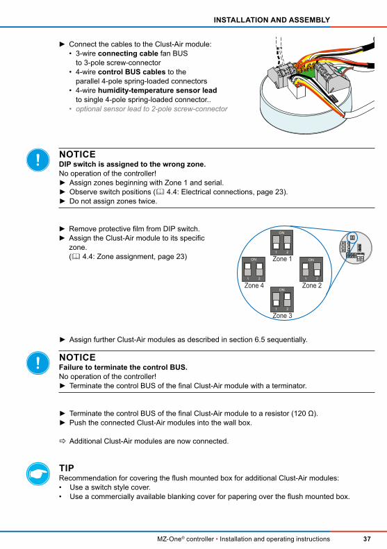
NOTICEIn case the DIP switch is assigned to the wrong or no zone
the controller cannot gate the ventilation devices connected (no operation of the controller)! ► Assign zones beginning with Zone 1 and serial. ► Observe switch positions. ► Do not assign zones twice.
Switch positions
Living space Switch positions at the DIP switch Description
Zone 1 Both switches are turned of. The sliding switches are set in position 1/2.
Zone 2 Switch 1 is turned on. The sliding switch is set in position ON.
Switch 2 is turned of. The sliding switch is set in position 2.
Zone 3 Switch 1 is turned of. The sliding switch is set in position 1.
Switch 2 is turned on. The sliding switch is set in position ON.
Zone 4 Both switches are turned on. The sliding switches are set in position ON.
ON
1 2
ON
1 2
ON
1 2
ON
1 2
1
2
4
3
1 Casing2 Mini switch3 Mini switch number4 Sliding switch

24
PREPARATIONS PRIOR TO INSTALLATION
MZ-One® controller • Installation and operating instructions
5 Preparations prior to installation
5.1 Installation advices and installation sites
• Carefully read sections Installation and Electrical connections befor installing the controller to avoid installation errors. Installation and electrical connection of the controller must be performed by qualiied personnel.
• Observe the following steps before mounting the controller: Step 1: Disconnect the controller and live parts from power supply. Step 2: Secure the controller against being switched on again. Step 3: Check the disconnected parts for voltage.
• If possible, mount the wall box for the programming unit at a level of approx. 1.50 m over loor. Thus, operation is easier.
• The number of lush mounted boxes/plasterboard boxes required depends on the intended number of zones. One wall opening = for itting the MZ-One programming unit and the irst Clust-Air module Every additional Clust-Air module = one additional box Observe the maximum distances ( 4: Electrical connections).
• Assign each Clust-Air module to its speciic zone correctly. The zone assignment takes place on the DIP switch ( 4.4: Zone assignment).
• NOTICE: Use braided lex to connect the fan BUS. The fan BUS terminal can take wires with a cross-section of up to 1.5 mm². For connecting the fan BUS, we recommend using a LiYY3x0.75 round cable.
• NOTICE: Choose an appropriate installation site for the humidity-temperature sensor in order to assure accurate and representative humidity measurement. Humidity captured at the installation site must represent those in the room. Humidity-temperature sensor must be sited at a point in the room where air circulates.
5.2 Dimensions
DesignationWidth
[mm]
Height
[mm]
Depth
[mm]Dia. [mm]
Wall opening for lush-mounted box 60x66 ‒ ‒ 66 82
Flush-mounted box 60x66 – ‒ 66 60
Wall opening for plasterboard wall box 68x61 – – 61 68
Plasterboardwall box 68x61 – – 61 68
Casing for MZ-One controller 115 115 17 ‒
Control panel box 71 71 56 ‒
Power supply unit NT15-MZ 100 93 56 ‒
Humidity-temperature sensor FTS31 71 71 27 ‒

25
PREPARATIONS PRIOR TO INSTALLATION
MZ-One® controller • Installation and operating instructions
5.3 Dimensioned drawings
Flush mounted box
Fig. 11: Dimensioned drawing for lush mounted box 60x66
Flush mounted plasterboard box
Fig. 12: Dimensioned drawing for lush mounted plasterboard box 68x61
MZ-One power supply unit
Fig. 13: Dimensioned drawing for MZ-One power supply unit NT15-MZ
2
Ø 6
0
Ø 6
6
Ø 7
6
1
66
Ø 8
0
Ø 6
0
≥ 70
2 2
3
1
1 Flush mounted box2 Fixing points controller base plate (4 x)
3 Wall opening
61
Ø 6
8
61
Ø 75
2
1
2
68
45
46,5
46,5
27,4
4756
3
93
100
7,5 64,75 55 5 5
1 Fixing screw controller base plate(2x) 2 Fixing screw for plasterboard box

26
PREPARATIONS PRIOR TO INSTALLATION
MZ-One® controller • Installation and operating instructions
Base plate of MZ-One controller casing
Fig. 14: Dimensioned drawing for base plate of MZ-One programming unit
MZ-One humidity-temperature sensor
Fig. 15: Dimensioned drawing for temperature-humidity sensor MZ-One
111,7
5
99
60
60
111,7
5
99
111,75
99
3
1
2
1
2
3
1 Locking hook for cover2 Hole for ixing screws (4 x)
3 Base plate of MZ-One programming unit
71
71
59
59
46
7
35
27
1
3
2
1 Ventilation slots2 Fixing points for base plate of temperature-humidity sensor (2 x)3 Receiving slots of temperature-humidity sensor (4 x)

27
INSTALLATION AND ASSEMBLY
MZ-One® controller • Installation and operating instructions
6 Installation and assembly
DANGERExposed electrical components.
Electric shock and injury due to live components (230V, 50Hz)! ► Before working on electrical installations, disconnect all afected equipment from the power supply. ► Observe the requirements for protection class II when laying the power supply cable. Do not lay live cables.
► Lay the fan BUS and power cables separately. ► The installation and connection must only be performed by qualiied and trained personnel.
6.1 Fitting the lush mounted box/plasterboard box
DANGERThe wall contains electrical cables.
Electric shock and injury due to live components (230V, 50Hz)! ► Before itting the wall openings, check for the presence of cables in the drilling area.
CAUTIONFalling masonry when itting the wall opening.Injury to persons and/or damage to property/looring!
► Protect looring against falling masonry. ► Remove objects from the immediate vicinity of the drilling area in the interior.
Hole cutter with Ø 82 mm drill bit (lush-mounted box) / Ø 68mm (plasterboard wall box)
Requirements: The masonry must be dry and in a load-bearing condition. The plasterboard wall must be inished. No lintels in the location of the planned drill holes.
Ö The wall openings for lush mounted boxes are ready.
Flush mounted box: Hole Ø 82 mm
Flush mounted plasterboard box: Hole Ø 68 mm
► Create the milled hole containing the boxes in the interior wall: • one for programming unit and irst Clust-Air module; • per additional module one hole.Observe the maximum cable lenghs ( 4).

28
INSTALLATION AND ASSEMBLY
MZ-One® controller • Installation and operating instructions
6.2 Connecting the power supply unit
DANGERExposed electrical components.
Electric shock and injury due to live components (230V, 50Hz)! ► Before working on electrical installations, disconnect all afected equipment from the power supply. ► Observe the requirements for protection class II when laying the power supply cable. Do not lay live cables..
► The installation and connection must only be performed by qualiied and trained personnel.
TIP: The MZ-One power supply unit is directly connected to the control panel. It takes up 6 pins on the control panel.
Requirements: None.
► Clip the power supply unit onto the top-hat rail in the control panel
► Connect the power supply unit (see section 4: electrical connections – Terminal assignment). • Attach the phase conductor to terminal L. • Attach the neutral conductor to terminal N. • Attach the (red) conductor to the (+) terminal. • Attach the (blue) conductor to the (–) terminal.
Ö The switching power supply unit is connected.
6.3 Laying cables
NOTEThe cable sheath on the fan-BUS provides no resistance when laid under plaster.
Risk of short circuit due to moisture penetration! ► Lay the cable in a conduit.
NOTICEWrong wiring of the Clust-Air modules.
No operation of the controller! ► Assign Clust-Air modules and lay control BUS sequentially.
NOTICELaying of cables whilst cable is live.
Damage to the controller! ► Only lay cables while they are not live. ► Installation only by trained and qualiied personnel.
LN
+–

29
INSTALLATION AND ASSEMBLY
MZ-One® controller • Installation and operating instructions
Wall chaser, hammer, chisel, iller for the plaster channels
Requirements: The wall openings must be completed. The power supply unit is connected.
Fig. 16: Schematic laying cables with star-shaped connection of the ventilation devices
• operating voltage cable, 2-wire• Control BUS, 4-wire, J-Y(ST)Y-2x2x0.8 telecommunications cable• Fan BUS, 3-wire, LiYY3x0.75 round cable (braided lex)• Humidity-temperature sensor lead, 4-wire, J-Y(ST)Y-2x2x0.8 telecommunications cable• Connecting cable external sensors (optional)
NOTICE: Laid cables must project by about 150 mm (Fan BUS cables at least 500 mm) from the wall opening, da sonst das Anschließen der Kabel nicht mehr möglich ist
► Lay 2-wire operating voltage cable in the plaster channel between the power supply unit and the wall opening for the MZ-One programming unit.
► Lay 4-wire control BUS cable between the wall opening for the MZ-One programming unit, and the opening for the second Clust-Air module.
► Lay 4-wire control BUS cables sequentially between the remaining Clust-Air module openings.
► Lay 3-wire fan BUS cable (3-wire, braided lex) between the fan and the wall opening for the Clust-Air module.
► Lay 4-wire temperature-humidity sensor lead, between the wall opening for the Clust-Air module and the installation site of the temperature-humidity sensor (in the room's air low and on average room height (approx. 1.40 m).
► Lay 2-wire leads for optional sensors between the wall opening for the Clust-Air module and the installation site of the optional sensor.
Ö All necessary cables are in place.
ma
x. 1
5 m
max
. 33
m
PSUProgramming
unit
Clust-Air module with connected fans

30
INSTALLATION AND ASSEMBLY
MZ-One® controller • Installation and operating instructions
6.4 Installing the programming unit and irst Clust-Air module
NOTICELaying of cables whilst cable is live.
Damage to the controller! ► Only lay cables while they are not live. ► Installation only by trained and qualiied personnel.
The MZ-One programming unit is mounted onto a wall box. Inside the wall box for the program-ming unit the irst Clust-Air module ist connected. As an option it is possible to install the MZ-One programming unit inside the control panel. In this case, the irst Clust-Air module may be connected inside the control panel box.
Installing the lush mounted box/plasterboard box
TIP: In the following the installation of the lush mounted box is shown. Installation of the lush mounted plasterboard box and control panel box is similar. Also follow the instructions in italic and grey when connecting an optional sensor,
e. g. CO2 sensor, or linking up to a home automation system.
Filler for mounting the box
Requirements: The wall openings are created. The cables are laid.
Ö The wall box is itted.
► Break open one cable entry • for each pair of fans • for the control BUS cable • for the operating voltage cable • for the temperature-humidity sensor lead • for the optional sensor lead in the lush-mounted box.
► Insert the prepared lush-mounted box into the wall opening.
► Fill the space between the interior wall and the box with a suitable iller.
► Lay the • fan BUS cables each in pairs • control BUS, 4-wire • operating voltage cable, 2-wire • humidity-temperature sensor lead, 4-wire • optional sensor lead into the lush-mounted box.

31
INSTALLATION AND ASSEMBLY
MZ-One® controller • Installation and operating instructions
TIP: As an option the fan BUS may be attached directly to the 3-pole connector on the Clust-Air module. Observe the screw terminal's capacity of max. 1.5 mm².
Connecting the Clust-Air module
Also follow the instructions in italic and grey when connecting an optional sensor,
e. g. CO2 sensor, or linking up to a home automation system.
Stripping tool, terminal blocks (5-pole, 3 x), additional fan cable (3-wire), additional control BUS (4-wire)
Requirements: The wall box is in place.
► Strip back about 70 mm of insulation from each cable.
► Connect the fan-BUS cables to terminal blocks, 5-pole, as follows: The cable ends • of the same colour • of ventilation devices in paired operation should be connected to the same pole of the terminal blockÖ A maximum of 4 poles are assigned with 2 cables each.
► Attach the cable ends of the additional con-necting cable, 3-wire, to the terminal block of the corresponding colour.
► Push the connected terminal blocks into the box.Ö The additional connecting cable projects into the room.
► Attach ferrules to the wire-ends of the additional connecting cable, 3-wire.Ensure to use wire end ferrules plus collar.

32
INSTALLATION AND ASSEMBLY
MZ-One® controller • Installation and operating instructions
NOTICEWrong wiring of the Clust-Air module.
MZ-One controller or components connected to the controller without function! ► Ensure that the terminal assignment is observed when connecting the cables. ( 4.2: Interfaces and terminal assignment/ igure 12, page 22).
NOTICEDIP switch is assigned to the wrong zone.
No operation of the controller! ► Assign zones beginning with Zone 1 and serial. ► Observe switch positions ( 4.4: Electrical connections, page 23). ► Do not assign zones twice.
Ö The Clust-Air module is connected.
NOTICEFailure to terminate the control BUS. No operation of the controller!
► Attach the terminator instead of the additional control BUS cable, if no further Clust-Air modules are being attached.
► Connect the cables to the Clust-Air module: • 3-wire connecting cable fan BUS to 3-pole screw-connector • 4-wire control BUS cable to one of the parallel 4-pole spring-loaded connectors • 4-wire humidity-temperature sensor lead to single 4-pole spring-loaded connector.. • optional sensor lead to 2-pole screw-connector
► Remove protective ilm from the DIP switch. ► Assign the Clust-Air module to zone 1. ( 4.4: Zone assignment, page 23)
ON
1 2
Zone 11 2
ON
Zone 2ON
1 2
Zone 3
Zone 4
ON
1 2 1 2
ON
► Connect the additional 4-wire control BUS to the second parallel 4-pole spring-loaded connector for the control BUS.
► Push the connected Clust-Air module into the wall box.

33
INSTALLATION AND ASSEMBLY
MZ-One® controller • Installation and operating instructions
Installing the MZ-One programming unit
NOTICEConnection of cables whilst cable is live.
Damage to the controller! ► Only connect cables while they are not live. ► Installation only by trained and qualiied personnel.
NOTICEContamination of the controller during building or renovation work.
This can afect its operation! ► Complete any building or renovation work prior to installing the controller.
Screws, Screw driver
Requirements: Operating voltage cable is in place. The Clust-Air module is connected.
► Press in the locking hooks (green arrows) at the bottom section of the base plate.Ö The cover unclips from the bottom section.
► Pull forward the cover to release it from the base plate.
2
1
3
► Secure the controller base plate to the box using the ixing screws.

34
INSTALLATION AND ASSEMBLY
MZ-One® controller • Installation and operating instructions
NOTICEWrong wiring on the programming unit's rear side.
leads to MZ-One controller or components connected to the controller without function! ► Ensure that the terminal assignment is observed when connecting the cables. ( 4.2: Interfaces and terminal assignment, ig. 11, page 22).
Ö MZ-One programming unit is installed.
► Connect the 2-wire operating voltage cable via lustre terminal.
► Attach the 4-wire control BUS cable to the 4-pole connector on the rear side of the pro-gramming unit cover.
► Turn the programming unit cover.Ö The cables are pointing towards the box.
– B A +
– +
► Hook the programming unit cover into the upper notches (green arrows) on the program-ming unit base plate.
► Press the bottom section of the programming unit cover towards the base plate.Ensure that the programming unit cover audibly snaps into place on the bottom sections locking hooks of the programming unit base plate.
2
1

35
INSTALLATION AND ASSEMBLY
MZ-One® controller • Installation and operating instructions
6.5 Installing additional Clust-Air modules
NOTICEConnection of cables whilst cable is live.
Damage to the controller! ► Only connect cables while they are not live. ► Installation only by trained and qualiied personnel.
Installing the wall box
TIP: In the following the installation of the lush mounted box is shown. Installation of the lush mounted plasterboard box is similar. Also follow the instructions in italic and grey when connecting an optional sensor,
e. g. CO2 sensor, or linking up to a home automation system.
Filler for mounting the box
Requirements: The wall openings are created. The cables are laid.
Requirements: The wall openings must be completed. The cables are in place.
Ö The wall box is installed.
► Break open one cable entry • for each pair of fans • for the control BUS cable (facing) • for the temperature-humidity sensor lead • for the optional sensor lead in the lush-mounted box.
► Insert the prepared lush-mounted box into the wall opening.
► Fill the space between the interior wall and the box with a suitable iller.
► Lay the • fan BUS cables each in pairs • control BUS cables, 4-wire, through facing entries • humidity-temperature sensor lead, 4-wire • optional sensor lead into the lush-mounted box.

36
INSTALLATION AND ASSEMBLY
MZ-One® controller • Installation and operating instructions
Connecting the Clust-Air module
Also follow the instructions in italic and grey when connecting an optional sensor,
e. g. CO2 sensor, or linking up to a home automation system.
Stripping tool, terminal blocks (5-pole, 3 x), additional fan cable (3-wire)
Requirements: The lush mounted box/ plasterboard box/ control panel box are in place.
TIP: As an option the fan BUS may be attached directly to the 3-pole connector on the Clust-Air module. Observe the screw terminal's capacity of max. 1.5 mm².
NOTICEWrong wiring of the Clust-Air module.
MZ-One controller or components connected to the controller without function! ► Ensure that the terminal assignment is observed when connecting the cables. ( 4.2: Interfaces and terminal assignment/ igure 12, page 22).
► Strip back about 70 mm of insulation from each cable.
► Connect the fan-BUS cables to terminal blocks, 5-pole, as follows: The cable ends • of the same colour • of ventilation devices in paired operation should be connected to the same pole of the terminal blockÖ A maximum of 4 poles are assigned with 2 cables each.
► Attach the cable ends of the additional con-necting cable, 3-wire, to the terminal block of the corresponding colour.
► Push the connected terminal blocks into the box.Ö The additional connecting cable projects into the room.
► Attach ferrules to the wire-ends of the additio-nal connecting cable, 3-wire.Ensure to use wire end ferrules plus collar.
37
INSTALLATION AND ASSEMBLY
MZ-One® controller • Installation and operating instructions
► Assign further Clust-Air modules as described in section 6.5 sequentially.
NOTICEFailure to terminate the control BUS.
No operation of the controller! ► Terminate the control BUS of the inal Clust-Air module with a terminator.
► Terminate the control BUS of the final Clust-Air module to a resistor (120 Ω). ► Push the connected Clust-Air modules into the wall box.
Ö Additional Clust-Air modules are now connected.
TIPRecommendation for covering the lush mounted box for additional Clust-Air modules: • Use a switch style cover. • Use a commercially available blanking cover for papering over the lush mounted box.
NOTICEDIP switch is assigned to the wrong zone.
No operation of the controller! ► Assign zones beginning with Zone 1 and serial. ► Observe switch positions ( 4.4: Electrical connections, page 23). ► Do not assign zones twice.
► Connect the cables to the Clust-Air module: • 3-wire connecting cable fan BUS to 3-pole screw-connector • 4-wire control BUS cables to the parallel 4-pole spring-loaded connectors • 4-wire humidity-temperature sensor lead to single 4-pole spring-loaded connector.. • optional sensor lead to 2-pole screw-connector
► Remove protective ilm from DIP switch. ► Assign the Clust-Air module to its speciic zone. ( 4.4: Zone assignment, page 23)
ON
1 2
Zone 11 2
ON
Zone 2ON
1 2
Zone 3
Zone 4
ON
1 2 1 2
ON

38
INSTALLATION AND ASSEMBLY
MZ-One® controller • Installation and operating instructions
6.6 Installing the Humidity-temperature sensor
DANGERThe wall contains electrical cables.
Electric shock and injury due to live components (230V, 50Hz)! ► Before itting the wall openings, check for the presence of cables in the drilling area.
NOTICEConnection of cables whilst cable is live.
Damage to the controller! ► Only connect cables while they are not live. ► Installation only by trained and qualiied personnel.
Drilling holes for the humidity-temperature sensor
Drilling machine with Ø 6mm drilling bit
Requirements: Humidity-temperature sensor lead is connected to the Clust-Air module. Avoid lintels when drilling boreholes. (average room heigt, approx. 1.40 m)
Ö The holes for the humidity-temperature sensor are in place.
Fitting the humidity-temperature sensor
NOTICEDamage to the humidity-temperature sensor PCB and/or contamination of the sensor due
to construction and renovation works.
Risk of inaccurate humidity capture! ► Never touch the PCB of the humidity sensor when itting the sensor. ► Complete construction and renovation works before itting the sensor. ► Remove objects from the immediate vicinity of the drilling area in the interior.
► Drill 6 mm diameter holes for rawl plugs in the interior wall.Ensure that the centre-to-centre distance of the holes is 46 mm.Ensure that there is one hole above thetemperature-humidity sensor lead and one below.
46
6

39
INSTALLATION AND ASSEMBLY
MZ-One® controller • Installation and operating instructions
Drilling machine with Ø 6mm drilling bit, rawl plugs, screws, screw driver
Requirements: The holes for the humidity-temperature sensor are in place.The humidity-temperature sensor lead is in place.
TIP: Inadequate circulation of the sensor causes wrong measurement. The ventilationslots on the humidity-temperature sensor must face up and down for an optimal circulation.
Ö The humidity-temperature sensor is installed..
► Drill two holes for the ixing screws on the base plate.
► Drill a cable entry for the sensor lead on the base plate.
► Feed the humidity-temperature sensor lead through the created cable entry.
► Secure the base plate to the interior wall using two ixing srews.
► Connect the humidity-temperature sensor lead to the 4-pole connector. ( 4.2: Interfaces and terminal assignment / Fig. 12, page 22). –
NC
DATA
+
► Locate the mounting pins on the cover of the hu-midity-temperature sensor in the receiving slots on the base plate.Ensure that the ventilation slots face up and down.

40
COMMISSIONING
MZ-One® controller • Installation and operating instructions
7 Commissioning
Once the MZ-One programming unit, its associated Clust-Air modules and the humidity-tempe-rature sensor have been installed and connected to the ventilation unit, it can be commissioned.Commissioning is essentially limited to checking the units that are connected to the controller and the functionality of the user interface. Comissioning takes about 30 seconds..
When the system is switched on, the following checks are made:• how many zones are connected to the appliance.• are the interfaces on the Clust-Air modules assigned.• is the user interface working properly.
NOTICEThe MZ-One controller may not recognise all devices connected to it.
Devices that are not recognised cannot be controlled! ► Set an address for each Clust-Air module by means of the DIP switches. ► Check whether the MZ-One controller has recognised all connected devices.
7.1 Functional test
Requirements: The ventilation system and controller are installed.Mains power is 'live'.
► Check whether the controller found all connected devices:
Fig. 17: Screen of functional test
Indicator 0 1
Meaning Clust-Air module not found Clust-Air module found
► Switch on the controller.Ö The controller searches internally for connected devices.Ö The number of devices found is indicated on the Devices line.
FRAM... ok
Devices... 1 1 0 0
FRAM... ok
Devices... 1 1 0 0
1234
1 Indicator for Clust-Air module 42 Indicator for Clust-Air module 3
3 Indicator for Clust-Air module 24 Indicator for Clust-Air module 1

41
COMMISSIONING
MZ-One® controller • Installation and operating instructions
Ö Connected devices are checked.
TIP: We recommend only to connect the controller when all connected devices are found (see functional test). If you are not sure wether all devices are found, you can carry out another func-tional test by tapping the navigation arrows and simultaneously for longer than 5 seconds.
Display Key Indicator 0 Indicator 1
UP Navigation arrow
Touch-sensitive key not tapped.
Touch-sensitive key tapped.
DOWN Navigation arrow
LEFT Navigation arrow
RIGHT Navigation arrow
When the display for the functional test of the touch-sensitive keys appears, the indicator 0 (touch-sensitive key not tapped) must be assigned to every key.
If the display appears and one or more keys are assigned to the indicator 1, an error occured:
1 Check the wiring inside the programming unit: Remove the control BUS cable from the immediate vincinity of the user interface. Remove the operating voltage cable from the immediate vincinity of the user interface.
2 Carry out another functional test.
► Check whether the touch-sensitive keys are working properly by tapping the keys (navigation arrows) one after another.
Ö When tapping the navigation arrow its indicator changes from 0 to 1.
After about 30 seconds the controller shows the main screen automatically. By simultaneously tapping the navigation arrows and for more than 10 seconds you can manually switch to the main screen.
FRAM... ok
Devices... 1 1 0 0
done
► The controller switches to the screen of the touch-sensitive keys functional test.Ö Function of the touch-sensitive keys is indicated.
Button Test
UP: 0 D0WN:0
LEFT: 0 RIGHT: 0

42
COMMISSIONING
MZ-One® controller • Installation and operating instructions
7.2 Connection
Requirements: Functional test successful.
Ö The MZ-One controller is commissioned.
After commissioning, settings that need to be changed from the factory-set can be altered.
► Tap navigation arrow three times.Ö The main settings menu is active.
>settings
7-day timer
inputs
limits
► Select menu item connection using navigation arrow .Ö The marker arrow points towards the menu item connection.
► Tap navigation arrow to confirm.
settings
>connection
information
factory settings
► The controller searches internally for connected devices, e. g. Clust-Air modules.Ö The number of devices found is indicated on the found line.
searching. .
found: 4

43
OPERATION
MZ-One® controller • Installation and operating instructions
8 Operation
8.1 Menu structure
inVENTer
MZ-0ne
01.06.2015 12:42
> Leistung <Zone1>
Leistung :
Modus : WRG
Dauer : 02 h
Zone 1
DL t |rF | LE
Ist : 29°C| 32%|
Soll: --- | 80%|
> Einstellungen
Wochenschaltuhr
Eingaenge
Grenzwerte
Wochenschaltuhr
>Zone 1 An
Zone 2 Aus
Zone 3 Aus
Einstellungen
>Wochenschaltuhr
Eingaenge
Grenzwerte
> Wochenschaltuhr
So 00 - 02 h
WRG
Le:
> Eingaenge
Zone1 < Aus >
Zone2 <ext. Schalt>
Zone3 < Analog >
> Grenzwerte
< Zone 1 >
Feuchtigkeit : 80%
Einstellungen
>Filterwechsel
Leistungsstufen
Betriebsstunden
Filterwechsel
>Filter gewechselt?
Dauer : 12 Wochen
Rest : 0 Wochen
> Leistungsstufen
= 25 %
= 50 %
= 100 %
>Betriebsstunden
Zone1: 50 h
Zone2: 50 h
Zone3: 50 h
Einstellungen
>Anzeige
Datum & Uhrzeit
Sprache
> Datum & Uhrzeit
Datum 28.04.2015
Uhrzeit 06:08
Wochentag Di
> Sprache
[x] Deutsch
[ ] English
> Anzeige
Helligkeit : 80 %
Dauer : 20 sec
Einstellungen
>Kopplung
Information
Werkseinstellungen
Information
MZ-0ne
HW:1.0 SW:1.05
SN: 420150402
Werkseinstellungen
RESET >>>
back <<<
searching. .
found: 4
Einstellungen
>Sensor Aktivierung
>Sensor Aktivierung
Zone1 <An >
Zone2 <Aus>
Zone3 <Aus>
8.3, S. 45
8.4, S. 46
8.7, S. 48
8.5 ff, S. 47 ff.
8.12, S. 57
8.8, S. 53
8.10, S. 54
8.11, S. 54
8.13, S. 58
8.14, S. 60
8.15, S. 61
8.16, S. 62
8.17, S. 63
8.18, S. 64
8.19, S. 64
7.2, S. 42

44
OPERATION
MZ-One® controller • Installation and operating instructions
8.2 Main screen
The main or default screen is the standard screen displayed when the MZ-One controller is activated. The main screen shows the inVENTer logo as well as the current date and time.
Depending on the actual situation, the additional info display line will also inform you of any current deviations from the 7-day timer (e.g. dehumidiication of a zone).
TIP: If no input is made, the main screen switches itself of after 20 seconds (factory setting).
Fig. 18: Main screen on MZ-One Controller
The Display and Operation menus can be selected from the main screen:
Tap the touch-sensitive navigation arrow to reach the manual control menu. Here, entries inthe 7-day timer can be manually altered.
Or
Tap navigation arrow to switch to the following screens:
• Main screen• Main Zone menu ( 8.4)• Main Settings menu ( 8.5 f.)
Tap navigation arrow to move through the screens in the opposite direction.
To return to the next higher level menu, select the irst line of the menu using navigation arrow and tap .
Tap the navigation arrows and simultaneously shorter than 5 seconds to return to the main screen from each selected screen.
inVENTer
MZ-0ne
01.06.2015 12:42
1
2
34
5
1 Manufacturer2 Device name3 Time
4 Date5 Additional info display line

45
OPERATION
MZ-One® controller • Installation and operating instructions
8.3 Gaining manual control
In addition to the pre-programmed settings for the 7-day timer, depending on the situation, each zone can be controlled manually by means of the Manual control menu.
TIP: The manual control has priority to the settings in the 7-day timer. Values programmed in the 7-day timer are not changed permanently by inputs in the menu manual control but overwritten for the selected period of time!
Requirements: The main screen must be shown.
TIP: When selecting the sleep timer mode (of mode) the MZ-One controller switches back to the previos set operating mode after the set interval. As previous set the controller notices the ! Select the menu item of • using navigation arrow to ensure the controller works in heat recovery mode after the
sleep timer interval. • using navigation arrow to ensure the controller works in ventilation mode after the
sleep timer interval.
Ö The ventilation system is now under manual control.
► Tap navigation arrow .Ö The output menu is displayed.
► Select the required zone using the navigation arrows or .
>output <zone1>
output :
mode : HR
interval : 02 h
► Select the menu item output using navigation arrow .Ö Output level flashes.
► Tap navigation arrows or to determine the output level under manual control.
output <zone1>
>output :
mode : HR
interval : 04 h
► Select the menu item mode using navigation arrow .Ö Operating mode flashes.
► Tap navigation arrows or to determine the operating mode under manual control.
output <zone1>
output :
>mode : V
interval : 02 h
► Select the menu item interval using navigation arrow .Ö Interval flashes.
► Tap navigation arrows or to determine the duration under manual control.
output <zone1>
output :
mode : V
>interval : 04 h

46
OPERATION
MZ-One® controller • Installation and operating instructions
TIP: Actual information of changes when the controller is under manual control are displayed in the main Zone menu, 8.4.The current operating mode and its duration are shown alternately lashing
Ö Actual information is displayed.
8.4 Main Zone menu
Fig. 19: MZ-One controller main Zone menu
No settings can be changed in the zone menu. The parameters currently set for each zone are shown.
You can navigate the main zone menu by means of the user interface by tapping navigation arrows and . The next service unit's parameters are displayed when you tap navigation arrow . You return to the main screen by tapping navigation arrow .
Tapping navigation arrow will take you to the main settings menu.
► Select the main Zone menu ( 8.4). ► Select the required zone using the navigation arrows or .
zone 1
V t | rh | LV
act.: 29°C| 32%|
set : --- | 80%|
zone 1
HR t | rh | LV
act.: 29°C| 32%|
set : --- | 80%|
1
7
2
3
5 46
1 Zone (service unit)2 Current output level3 Output level when limit is exceeded4 Relative humidity limit5 Current relative humidity level
6 Current temperature7 Currnet operating mode
or (Operating mode/Interval alternately lashing when under manual control)
47
OPERATION
MZ-One® controller • Installation and operating instructions
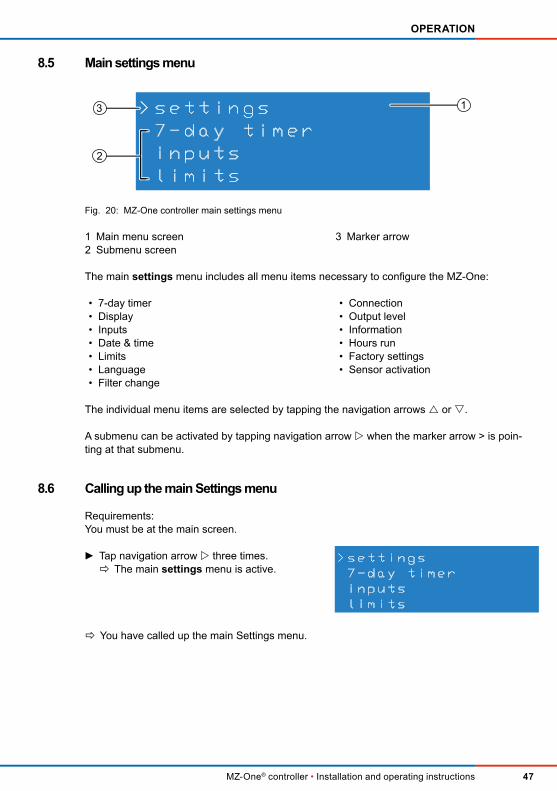
8.5 Main settings menu
Fig. 20: MZ-One controller main settings menu
The main settings menu includes all menu items necessary to conigure the MZ-One:
The individual menu items are selected by tapping the navigation arrows or .
A submenu can be activated by tapping navigation arrow when the marker arrow > is poin-ting at that submenu.
8.6 Calling up the main Settings menu
Requirements: You must be at the main screen.
Ö You have called up the main Settings menu.
>settings
7-day timer
inputs
limits
13
2
1 Main menu screen2 Submenu screen
3 Marker arrow
• 7-day timer• Display• Inputs• Date & time• Limits• Language• Filter change
• Connection• Output level• Information• Hours run• Factory settings• Sensor activation
► Tap navigation arrow three times.Ö The main settings menu is active.
>settings
7-day timer
inputs
limits
48
OPERATION
MZ-One® controller • Installation and operating instructions
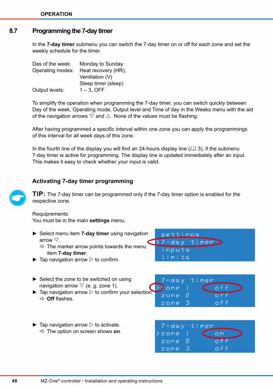
8.7 Programming the 7-day timer
In the 7-day timer submenu you can switch the 7-day timer on or of for each zone and set the weekly schedule for the timer.
Das of the week: Monday to Sunday Operating modes: Heat recovery (HR), Ventilation (V) Sleep timer (sleep) Output levels: 1 – 3, OFF
To simplify the operation when programming the 7-day timer, you can switch quickly between Day of the week, Operating mode, Output level and Time of day in the Weeks menu with the aid of the navigation arrows and . None of the values must be lashing.
After having programmed a speciic interval within one zone you can apply the programmings of this interval for all week days of this zone.
In the fourth line of the display you will ind an 24-hours display line ( 3), if the submenu 7-day timer is active for programming. The display line is updated immediately after an input. This makes it easy to check whether your input is valid.
Activating 7-day timer programming
TIP: The 7-day timer can be programmed only if the 7-day timer option is enabled for the respective zone.
Requiprements: You must be in the main settings menu.
► Select menu item 7-day timer using navigation arrow .Ö The marker arrow points towards the menu item 7-day timer.
► Tap navigation arrow to confirm.
settings
>7-day timer
inputs
limits
► Select the zone to be switched on using navigation arrow (e. g. zone 1).
► Tap navigation arrow to confirm your selection.Ö Off flashes.
7-day timer
>zone 1 off
zone 2 off
zone 3 off
► Tap navigation arrow to activate.Ö The option on screen shows on.
7-day timer
>zone 1 on
zone 2 off
zone 3 off

49
OPERATION
MZ-One® controller • Installation and operating instructions
► Tap navigation arrow to access the menu for adjusting the 7-day timer.
>7-day timer
Sun 00 - 02 h
HR
Lv:
Ö The 7-day timer for the selected unit is enabled.Ö Settings can now be altered.
Selecting an interval
The interval deines the period in which the selected settings are active. The periods are display-ed as times of day. The MZ-One controller ofers 12 intervals, each of them a two hour period. The predeined intervals cannot be altered.
Requirements: The 7-day timer for the selected zone must be enabled.
Ö The interval has been selected.
Selecting day of week
Requirements: The 7-day timer for the selected zone must be enabled.
Ö The day of the week has been selected.
► Select menu item interval using navigation arrow .
► Tap navigation arrow to confirm.Ö Interval flashes.
► Select the required period using navigation arrow or .
► Tap navigation arrow to confirm.Ö Interval stops flashing.
7-day timer
Sun > 02 - 04 h
HR
Lv:
7-day timer
Sun > 00 - 02 h
HR
Lv:
► Select menu item day of week using navigation arrow .
► Tap navigation arrow to confirm.Ö Day of week flashes.
► Select the required day of week using navigation arrow or .
► Tap navigation arrow to confirm.Ö Day of week stops flashing.
7-day timer
> Mon 02 - 04 h
HR
Lv:
7-day timer
> Sun 02 - 04 h
HR
Lv:

50
OPERATION
MZ-One® controller • Installation and operating instructions
Selecting the operating mode
With this option you can determine the operating mode for the selected interval. Dehumidiication mode (EF) is triggered only by the temperature-humidity sensor and cannot be set manually.
Requirements: The 7-day timer for the selected zone must be enabled.
Ö The operating mode has been selected.
Setting the output level
Using the output level option, an output level 1 to 3 or OFF is assigned to the interval.
Requirements: The 7-day timer for the selected zone must be enabled.
Ö The output level has been set.
► Select menu item mode using navigation arrow .
► Tap navigation arrow to confirm.Ö Operating mode flashes.
► Select the required operating mode using navigation arrow or .
► Tap navigation arrow to confirm.Ö Operating mode stops flashing.
7-day timer
Mon 02 - 04 h
> V
Lv:
7-day timer
Sun 02 - 04 h
> HR
Lv:
► Select menu item output level using navigation arrow .
► Tap navigation arrow to confirm.Ö Output level flashes.
► Select the required operating mode using navigation arrow or .
► Tap navigation arrow to confirm.Ö Output level stops flashing.
7-day timer
Mon 02 - 04 h
V >
Lv:
7-day timer
Mon 02 - 04 h
V >
Lv:

51
OPERATION
MZ-One® controller • Installation and operating instructions
Applying currently set data
TIP: Data changes and the programmings of an 7-day timer's interval may be applied to each day of the week. Thus, settings in the 7-day timer can be accomplished faster and easier.
Requirements: Data for a 7-day timer's interval are set. Or
Changes to the values in a 7-day timer's interval have been made. The 7-day timer for the selected zone must be enabled. No value lashes.
The new opened display allows you to apply the current programmings and/or changes made to the selected interval to each day of the week.
Please observe that:
• Changes may only be transferred for the current interval. If the interval is changed, it is neccessary to make another transfer.
• Data transfers are only possible for the current zone. The values for each zone must be programmed and transferred separately.
Ö Interval's data is applied to every day of the week.
TIP: In case the changes/current programmings shall not be applied, you can leave the menu by tapping the navigation arrow . The changes are not applied to other week days.You will re-enter the enabled 7-day timer display for your currently selected zone and may carry out other changes.As long as no values were changed, ..ok will be displayed on the tranfer display, even if you have left the display in the meantime.
► Tap navigation arrow .Ö The marker arrow is set to the next menu item.
► Tap navigation arrow again until a new display opens up.
7-day timer
apply data to
every day?
>yes
7-day timer
Mon 02 - 04 h
> V
Lv:
► Tap navigation key to apply the interval's set data to each day of the week.Ö ..ok appears on the display as confirmation.
7-day timer
apply data to
every day?
>yes ..ok

52
OPERATION
MZ-One® controller • Installation and operating instructions
8.8 Setting the ilter change interval
TIP: If you wish, the MZ-One controller can remind you to change the ilter. The degree of contamination of the ilter is not captured automatically. Therefore set an interval according to your own observations. The factory setting is an interval of 14 weeks.
Menu item Description
Interval• Displays the currently selected ilter change interval Minimum: 1 week Maximum: 52 weeks
Residu • Time, until next ilter change is necessary
Requirements: You must be in the main settings menu.
Ö The ilter change interval has been set.
► Select menu item ilter change using navigation arrow or .Ö The marker arrow points towards the menu item filter change.
► Tap navigation arrow to confirm.Ö The submenu filter change opens up.
► Select the menu item interval using navigation arrow .
► Tap navigation arrow to confirm.Ö Interval flashes.
► Tap navigation arrow oder to increase or reduce the number of weeks between filter changes.Ö Residu is set back to the currently selected filter change interval.
filter change
Filter changed?
>interval: 14 weeks
residu : 8 weeks
settings
>filter change
output levels
hours run
filter change
Filter changed?
>interval: 12 weeks
residu : 12 weeks

53
OPERATION
MZ-One® controller • Installation and operating instructions
8.9 Conirming ilter change
When the ilter needs to be changed, instead of the main screen, the Filter change screen opens. Once you have changed the ilter, the change must be conirmed at the controller.
Requirements: ilter change must be displayed on the main screen.
Fig. 21: Screen display for ilter change
Ö The ilter change has been conirmed.
TIP: In case you want to change the interval directly after conirming the change you can directly select the menu item interval. After changing the interval you have to conirm a ilter change again by selecting Filter changed? and tapping the navigation arrow .
filter change
► Tap a navigation arrow of your choice for at least 5 seconds.Ö The main sreen is displayed.
inVENTer
MZ-0ne
01.06.2015 12:42
► Tap navigation arrow three times.Ö The main settings menu is called up.
>settings
7-day timer
inputs
limits
► Select menu item ilter change using navigati-on arrow or .Ö The marker arrow points towards the menu item filter change.
► Tap navigation arrow to confirm.Ö The submenu filter change opens up.
settings
>filter change
output levels
hours run
► Select the menu item Filter changed? using navigation arrow .
► Tap navigation arrow to confirm.Ö Residu is set back to the currently selected filter change interval.
filter change
>Filter changed?
interval: 12 weeks
residu : 0 weeks

54
OPERATION
MZ-One® controller • Installation and operating instructions
8.10 Setting the language
TIP: Two languages are available on your MZ-One controller. Standardised these two are english and your local language (if english is your local language the second language is in standard version set to german). The factory-set languages on your MZ-One are displayed in the language menu. In this menu, changing between the factory-set languages is possible as well.
Requirements: You must be in the main settings menu. The set language is german.
Ö The language setting is changed.
8.11 Setting the date and time
TIP: The MZ-One controller does not change automatically between daylight saving time and standard time. Also date changes due to leap years are not recognised automatically. All changes of time and date have to be made manually.
Calling up the Date & time submenu
Requirements: You must be in the main settings menu.
► Select the menu item Sprache using navigation arrow or .Ö The marker arrow points towards the menu item Sprache.
Einstellungen
Anzeige
Datum & Uhrzeit
>Sprache
► Tap navigation arrow to confirm.Ö The language submenu is open.
> Sprache
[x] Deutsch
[ ] English
► Select the line with the required language using navigation arrow .
► Tap navigation arrow to confirm.Ö The language is marked with an x.
language
[ ] Deutsch
> [x] English
► Select the menu item date & time using navigation arrow or .Ö The marker arrow points towards the menu item date & time.
settings
display
>date & time
language

55
OPERATION
MZ-One® controller • Installation and operating instructions
► Tap navigation arrow to confirm. >date & time
date 28.04.2015
time 06:08
day Tue
Ö The date & time submenu has been opened.
Setting the date
Requirements: You must be in the date & time submenu.
► Select the menu item date using navigation arrow .Ö The marker arrow points towards the menu item date.
date & time
>date 28.04.2015
time 06:08
day Tue
► Tap navigation arrow .Ö Day flashes.
► Set the current day using navigation arrow or .Ö The current day has been set.
date & time
>date 06.04.2015
time 06:08
day Tue
► Tap navigation arrow .Ö Month flashes.
► Set the current month using navigation arrow or .Ö The current month has been set.
date & time
>date 06.05.2015
time 06:08
day Tue
► Tap navigation arrow .Ö Year flashes.
► Set the current year using navigation arrow or .Ö The current year has been set.
date & time
>date 06.05.2016
time 06:08
day Tue
► Tap navigation arrow three times.Ö You are back in the date & time submenu.
Ö The date has been set.

56
OPERATION
MZ-One® controller • Installation and operating instructions
Setting the time
Requirements: You must be in the date & time submenu.
Ö The time is set.
Setting the day of the week
Requirements: You must be in the date & time submenu.
Ö The day of the week has been set.
► Tap navigation arrow .Ö Hours flashes.
► Set the hour using navigation arrow or .Ö The current hour has been set.
date & time
date 06.05.2015
>time 10:08
day Tue
► Tap navigation arrow .Ö Minutes flashes.
► Set the minutes using navigation arrow or .Ö The current minutes have been set.
date & time
date 06.05.2015
>time 10:58
day Tue
► Tap navigation arrow twice.Ö You are back in the date & time submenu.
► Tap navigation arrow .Ö Day of week flashes.
► Set the day of the week using navigation arrow or .Ö The day of the week has been set.
date & time
date 06.05.2015
time 10:58
>day Wed
► Tap navigation arrow once.Ö You are back in the date & time submenu.
► Select the menu item time using navigation arrow .Ö The marker arrow points towards the menu item time.
date & time
date 06.05.2015
>time 06:08
day Tue
► Select the menu item day of week using navigation arrow .Ö The marker arrow points towards the menu item day of week.
date & time
date 06.05.2015
time 10:58
>day Tue

57
OPERATION
MZ-One® controller • Installation and operating instructions
8.12 Enabling/ disabling the interface
In the inputs submenu, the interface for an additional optional sensor, e. g. the CO2 sensor,
on the Clust-Air module can be enabled and disabled. You will ind an overview of the terminal assignment of the interface in 4: Electrical connections – Terminal assignment. Select the inputs for optional sensors from the following table.
Sensor (optional) Input
Home automation system Analogue
Passive switch for activating manual dehumidiication ext. switch
Fireplace switch irepl. switch
CO2 sensor ext. switch
VOC sensor ext. switch
Enabling the interface
Requirements: You must be in the main settings menu. The external interface must be assigned on the Clust-Air module.
Ö The interface has been enabled.
► Tap navigation arrow to confirm.Ö The inputs submenu is open.
>inputs
zone1 < off >
zone2 < off >
zone3 < off >
► Select the zone of which the interface is being assigned using navigation arrow (e. g. zone 1).Ö The marker arrow points towards the zone.
► Tap navigation arrow .Ö off flashes.
inputs
>zone1 < off >
zone2 < off >
zone3 < off >
► Set the required input using navigation arrow or .
inputs
>zone1 <ext.switch >
zone2 < off >
zone3 < off >
► Select the menu item inputs using navigation arrow or .Ö The marker arrow points towards the menu item inputs.
settings
7-day timer
>inputs
limits

58
OPERATION
MZ-One® controller • Installation and operating instructions
Enabling the interface
Requirements: You must be in the main settings menu. The external interface must be enabled.
Ö The interface has been disabled.
8.13 Adjusting settings on the display unit
Feature Description
Brightness • Brightness of the backlighting during programmings/ entries Minimum: 25 % Maximum: 99 %
Interval
• Duration of the backlighting after your last entry.• After the set duration the display switches of automatically. Minimum: 10 seconds Maximum: 300 seconds
Calling up the Display submenu
Requirements: You must be in the main settings menu.
► Tap navigation arrow to confirm.Ö The inputs submenu is open.
>inputs
zone1 < off >
zone2 <ext. switch>
zone3 < analogue >
► Select the menu item inputs using navigation arrow or .Ö The marker arrow points towards the menu item inputs.
settings
7-day timer
>inputs
limits
► Select the zone of which the interface is being assigned using navigation arrow (e. g. zone 2).Ö The marker arrow points towards the zone.
► Tap navigation arrow .Ö The current interface flashes.
inputs
zone1 < off >
>zone2 <ext. switch>
zone3 < analogue >
► Set the input to off using navigation arrow or .
inputs
zone1 < off >
>zone2 < off >
zone3 < analogue >
► Select the menu item display using navigation arrow or .Ö The marker arrow points towards the menu item display.
settings
>display
date & time
language

59
OPERATION
MZ-One® controller • Installation and operating instructions
Ö The display submenu is open.
Setting the brightness of the backlighting
Requirements: You must be in the display submenu.
Ö The brightness of the display unit is set.
Adjusting the duration of the backlighting
Requirements: You must be in the display submenu.
Ö The duration of backlighting has been adjusted.
► Tap navigation arrow to confirm. >display
brightness : 99 %
interval : 20 sec
► Select the menu item brightness using navigation arrow .Ö The marker arrow points towards the menu item brightness.
► Tap navigation arrow .Ö Brightness value flashes.
► To increase or decrease the brightness level, tap navigation arrow or .
► Tap navigation arrow to confirm.Ö Brightness value stops flashing.
display
>brightness : 80 %
interval : 20 sec
► Select the menu item interval using navigation arrow .Ö The marker arrow points towards the menu item interval.
► Tap navigation arrow .Ö Interval value flashes.
► To shorten or lengthen the duration, tap navigation arrow or .
► Tap navigation arrow to confirm.Ö Interval value stops flashing.
display
brightness : 80 %
>interval : 50 sec

60
OPERATION
MZ-One® controller • Installation and operating instructions
8.14 Deining output levels
In the output levels submenu you can alter the preset factory settings ( 2.2: Function – D. Factory settings). You can set three output levels each for the heat recovery and ventilation modes and one out-put level for the dehumidiication mode.
The exact percentage value for an optimal airlow in your living spaces will depend on the venti-lation concept based on your premises. The setting of the output level is possible at between 25 and 100 % in steps of 5 %. We recommend to assign output level 2 to your ventilation concept's percentageand leave the ventilation system in this level as a standard.
TIP: To simplify the operation when setting output levels, you can navigate between output levels via the navigation arrows und . To do so, none of the options must be enabled (none of the values is flashing).
Requirements: You must be in the main settings menu.
► Tap navigation arrow to confirm.Ö The output levels submenu is open.
>output levels
= 25 %
= 50 %
= 100 %
► Select the menu item output levels using navigation arrow or .Ö The marker arrow points towards the menu item output levels.
settings
filter change
>output levels
hours run
► To increase or decrease the output in steps of 5 %, tap navigation arrow or .
output levels
= 25 %
> = 60 %
= 100 %
► Tap navigation arrow to confirm.Ö The output value stops flashing.
Ö The output levels for the heat recovery and ventilation modes have been set.
► Select the output level that you would like to adjust using the navigation arrow or . (e. g. output level 2).Ö The marker arrow points towards the selected output level.
► Tap navigation arrow .Ö The output value flashes.
output levels
= 25 %
> = 50 %
= 100 %

61
OPERATION
MZ-One® controller • Installation and operating instructions
Once you have set the output levels for the heat recovery and ventilation modes, you can adjust the output level for the dehumidiication mode.
To do so, tap navigation arrow (no value flashes, the marker arrow is moving) in the output levels submenu until a new screen opens up. Select the menu item dehumidiication mode by tapping navigation arrow . The output level value lashes. Proceed as previously described for changing output levels:
Ö The output levels have been redeined.
8.15 Deining limits for the temperature-humidity sensor
The limit deines the level of relative humidity at which the MZ-One controller switches all fans connected to the Clust-Air module to the dehumidiication mode. The limit is set to 80 % ex works. It can be set separately for each zone.
Requirements: You must be in the main settings menu.
► To increase or decrease the output in steps of 5 %, tap navigation arrow or .
► Tap navigation arrow to confirm.Ö The output value stops flashing.
output levels
> EF = 80 %
Ö The output level for the dehumidification mode has been set.
► Select the menu item limits using navigation arrow or .Ö The marker arrow points towards the menu item limits.
settings
7-day timer
inputs
>limits
► Tap navigation arrow to confirm.Ö The limits submenu is open.
>limits
< zone 1 >
humidity : 80%
► Tap navigation arrow to access zone selection.
► Select the required zone using navigation arrow or .Ö The marked zone is enabled.
limits
> < zone 2 >
humidity : 80%

62
OPERATION
MZ-One® controller • Installation and operating instructions
Ö The limit for the temperature-humidity sensor has been deined.
8.16 Activating/ deactivating the temperatre-humidity sensor
In case no temperature-humidity sensor is connected to the Clust-Air module No sensor lashes permanently on the third line of the main display. In the submenu sensor activation this notiication can be deactivated. Factory-set all sensors are activated.
Please note that in this menu only the temperature-humidity sensor can be enabled/disabled. Other optional sensors must be activated/deactivated in the interfaces menu ( 8.12).
Requirements: You must be in the main settings menu.
► Select the menu item humidity using navigation arrow .Ö The marker arrow points towards the menu item humidity.
► Tap navigation arrow .Ö Humidity value flashes.
limits
< zone 2 >
>humidity : 80%
► To set the limit downwards or upwards, tap navigation arrow or .Ö The limit is changed.
► Tap navigation arrow to confirm.Ö Humidity value stops flashing.
► Select the menu item sensor activation using navigation arrow .Ö The marker arrow points towards the menu item sensor activation.
settings
>sensor activation
► Tap navigation arrow to confirm.Ö The submenu sensor activation is open.
>sensor activation
zone1 <on >
zone2 <off>
zone3 <off>
► Select the zone of which the sensor is active (on) using navigation arrow . (e. g. zone 1).Ö The marker arrow points towards the selected zone.
sensor activation
>zone1 <on >
zone2 <off>
zone3 <off>
limits
< zone 2 >
>humidity : 70%

63
OPERATION
MZ-One® controller • Installation and operating instructions
Or
To re-activate the sensor select the option on for the disabled sensor:
Ö The temperature-humidity sensor is activated/deactivated.
8.17 Calling up information
In the information submenu you can view information about the hardware and software, as well as the serial number of your MZ-One controller.
Requirements: You must be in the main settings menu.
Ö The hardware version (HW) is displayed.Ö The software version (SW) is displayed.Ö The serial number (SN) is displayed.
► Tap navigation arrow or and switch the sensor to off.Ö The temperature-humidity sensor is deactivated.
sensor activation
>zone1 <off>
zone2 <off>
zone3 <off>
► Tap navigation arrow or and switch the sensor to on.Ö The temperature-humidity sensor is activated.
sensor activation
zone1 <off>
>zone2 <on >
zone3 <off>
► Select the menu item information using navigation arrow or .Ö The marker arrow points towards the menu item information.
settings
connection
>information
factory settings
► Tap navigation arrow to confirm.Ö The information submenu is open.
information
MZ-0ne
HW:1.0 SW:1.0
SN: 420150402

64
OPERATION
MZ-One® controller • Installation and operating instructions
8.18 Viewing hours run
Requirements: You must be in the main settings menu.
Ö The hours run for each zone can now be viewed.
8.19 Returning to factory settings
Requirements: You must be in the main settings menu.
Or
► Select the menu item hours run using navigation arrow or .Ö The marker arrow points towards the menu item hours run.
settings
filter change
output levels
>hours run
► Tap navigation arrow to confirm.Ö The submenu hours run is open.
>hours run
zone1: 50 h
zone2: 50 h
zone3: 50 h
► Select the zone whose hours run you want to check using navigation arrow .
► Select the menu item factory settings using navigation arrow or .Ö The marker arrow points towards the menu item factory settings.
settings
connection
information
>factory settings
► Tap navigation arrow to confirm.Ö The submenu factory settings is open.
factory settings
RESET >>>
back <<<
► Tap navigation arrow to return the MZ-One controller to its factory settings.Ö The controller has been returned to its factory settings.
Ö The MZ-One main screen is shown.
► Tap navigation arrow to exit the factory settings submenu (without reset).
Ö The main settings menu is displayed

65
OPERATION
MZ-One® controller • Installation and operating instructions
8.20 Carrying out a functional test
Requirements: The ventilation system and controller are installed.Mains power is 'live'.
Ö Functional test has been carried out.
8.21 Manually enabling/disabling the dehumidiication mode (optional)
A commercially available loating ON/OFF switch (N/O) may be connected to the Clust-Air mo-dule's external interface. With this switch, the dehumidiication mode also can be enabled and disabled manually as required.
Requirements: The loating switch contact interface is enabled. ( 8.12: Operation – Enabling/disabling interface)
Ö Dehumidiication mode has been enabled/disabled.
► Tap navigation arrows and simultaneously for longer than 5 seconds.Ö Functional test screen is shown.
FRAM... ok
Devices... 1 1 0 0
► Carry out the steps for the functional test described in 7.1: Comissioning – Functional test (page 40).
► Turn on the external switch.Ö Dehumidiication mode is enabled.
► Turn of the external switch.Ö Dehumidiication mode is disabled.

66
SERVICING AND MAINTENANCE
MZ-One® controller • Installation and operating instructions
9 Servicing and maintenance
CAUTIONServicing/maintenance by children and persons of limited ability.
Risk of injury and/or malfunctioning of the ventilation unit! ► All servicing and maintenance tasks should not be carried out by children or persons with restricted physical, sensory or mental capabilities or who lack of experience and/or knowledge to do so.
TIP: Disconnect the controller from the power supply for servicing and maintenace tasks.
The MZ-One controller is virtually maintenance free. All servicing and maintenance tasks may be accomplished by the user after a brief instruction.
Cleaning agents
NOTE: The MZ-One® controller consists of a scratch-sensitive glass panel and smooth plastic surfaces. Do not use detergents containing sand, soda, acids or chlorine to avoid damages to the surface.
Clean using a normal commercial detergent and warm water. The following equipment can be used for cleaning:
• Lint-free soft cloth• Soft paintbrush
Recommended maintenance schedule
The listed maintenance activities and intervals are recommendations of the inVENTer GmbH to ensure full functionality of your MZ-One® controller.
As required your personal maintenance schedule may deviate.
Interval Assembly Maintenance activity
MonthlyMZ-One programming unit
Clean the surface of the cover and lateral surfaces with a damp cloth.
MonthlyHumidity-temperature sensor
Clean ventilation slots with a soft paintbrush.Clean the surface of the cover with a damp cloth.

67
SPECIFICATION
MZ-One® controller • Installation and operating instructions
10 Speciication
Feature Value
Type of protection according to EN 61558 IP20
Protection class II
Input voltage power supply unit: mains supply [V AC] [Hz] 230, 50
Output voltage power supply unit: operating voltage [V DC] 24
MZ-One programming unit
Feature Value
Protection class III
Operating voltage [V DC] 24
Control BUS voltage [V DC] 24
Power consumption in standby mode [W] Max. 2.5 at 4 zones
Power consumption [W] Max. 0.5
Operating temperature [°C] 0 – 60
Dimensions [W x H x D in mm] 119 x 119 x 27.5
Clust-Air module
Feature Value
Protection class III
Operating voltage [V DC] 24
Control BUS output voltage [V DC] 24, 4-pole
Fan BUS output voltage [V DC] 6.8 – 15.3, 3-pole
Analogue input (optional)Control voltage 0 – 10 V DC
Resolution 10 bit
External contact (optional) Floating N/O
Power consumption [W] Max. 18
Humidity-temperature sensor FTS31
Feature Value
Set value, humidity sensor [% r. h.] 40 – 80
Humidity sensor interval [%] 5

68
STANDARD DELIVERY
MZ-One® controller • Installation and operating instructions
11 Standard delivery
Upon receipt, check the delivery for completeness and for any damage in transit against the delivery note. Report missing items within four weeks.
• MZ-One programming unit (black/white) • MZ-One power supply unit• Clust-Air module (1 x) • Pack (connectors, terminator)• Humidity-temperature sensor • Installation and operating instructions
Component Order number
MZ-One controller 1001-2005
Clust-Air module 1003-0081
Installation and operating instructions 5020-0002
12 Accessories and spare parts
Accessories
Component Order number
Clust-Air module CAM1 1003-0081
CO2 sensor CS1 1004-0145
Flush mounted plasterboard box 61x68 1003-0084
Flush mounted box 60x66 3002-0244
BUS cable J-Y(ST)Y2x2x0.8 Lg 1004-0113
Round cable LiYY-O 3x0.75 (33m) 1004-0020
Spare parts
Component Order number
MZ-One programming unit, white 2006-0091
MZ-One programming unit, black 2006-0092
MZ-One controlling module 3002-0258
MZ-One humidity-temperature sensor 3002-0264
PSU NT15-MZ Cabinet Mounted 3002-0260

69
TROUBLESHOOTING AND DISPOSAL
MZ-One® controller • Installation and operating instructions
13 Troubleshooting and disposal
Troubleshooting
Fault Possible cause Remedy
Screen lights up but no display.
Controller crashed.
Tap navigation arrows and simultaneously (shorter than 5 seconds) until main screen appears.
Disconnect controller briely from power supply.
MZ-One controller does not recognise a connected Clust-Air module.
DIP switch is assigned to the wrong zone.
Check that the switch settings on the Clust-Air module are assigned to the correct zone ( 4: , page 23).
Zone assigned twice.Assign zones beginning with Zone 1 and serial. Do not assign zones twice.
Clust-Air moduleassigned wrong ornot assigned.
Check wiring.
No contacting.Check wiring. Take care to strap enough insulation (approx. 65 mm). Give some play to the cables when wiring.
Navigation arrow cannot be tapped.
Wiring inside the programming unit to near to the user interface.
Remove wiring inside the programming unit from user interface (bend away).
Touch-sensitive keys defective.
Carry out functional test, page 40. When result key does not work: programming unit must be changed.
On Main display "No sensor" lashes permanently.
No temperature-humidity sensor connected to the Clust-Air module.
Deactivate sensor of the concerning Clust-Air module 8.12)
Contact your retailer or representative if the problem persists. Details can be found in 15: Service.
Disposal
Dispose of the product in line with applicable national regulations. The products de-scribed in these installation and operating instructions are broadly recyclable thanks to clean manufacturing processes. Please contact a waste management company specialising in electronic equipment for environmentally sustainable recycling and
disposal of your old system. Also dispose of the packaging in line with national regulations.
Product Material Disposal
Programming unit casing PS Plastic recycling
Programming unit glass panel Glass Waste
Clust-Air module/ power supply unit Electronics Drop-of centre for electronic equipment

70
WARRANTY AND GUARANTEE
MZ-One® controller • Installation and operating instructions
14 Warranty and Guarantee
Warranty
Outside Germany, the national warranty provisions of the country in which the system is sold apply. Please contact the distributor for your country.
The warranty refers to the defect-free condition of the product at the time of purchase and cov-ers all defects that were present at the time of purchase. Failure to observe the intended use will invalidate all warranty claims.
Manufacturer guarantee
inVENTer GmbH provides a ive-year guarantee for electrical components. This covers prema-ture product wear.
Further information about the warranty is available at www.inventer.de/guarantee
15 Service
Claims
Check the delivery for completeness and transport damage upon receipt using the delivery note. Report missing items immediately, and at the latest within 14 days to your supplier, distributor or factory representative.
Warranty and guarantee claims
In the case of a warranty or guarantee claim, contact your local distributor or factory represent-ative.
In all cases, please return the complete device to the manufacturer. The guarantee is an additional ofer by the manufacturer and in no way afects the applicable law.
Accessories and spare parts
To order parts for your controller, contact your nearest factory outlet or our service staf.
Technical customer service
For technical support contact our service staf.
TelephoneFaxE-mailInternet
+49 (0) 36427 211-0+49 (0) 34627 [email protected]://www.inventer.eu

71
WARRANTY AND GUARANTEE
MZ-One® controller • Installation and operating instructions
COMPANY DETAILS
PUBLISHER:
INVENTER GMBHORTSSTRASSE 4A
D-07751 LÖBERSCHÜTZGERMANY
TELEPHONE: +49 (0) 36427 211-0FAX: +49 (0) 36427 211-113
E-MAIL: [email protected]: WWW.INVENTER.EU
MANAGING DIRECTOR: ANNETT WETTIGVAT NO: DE 815494982
JENA DISTRICT COURT, COMPANY REG. NO. 510380
PICTURE CREDITS AND CONTENT COPYRIGHT: © INVENTER GMBH 20115-17
SUBJECT TO TECHNICAL MODIFICATIONS.ALL INFORMATION PROVIDED "AS IS".
NO LIABILITY ACCEPTED FOR PRINTING ERRORS..
COMPANY DETAILS

inVENTer GmbH
Ortsstraße 4aD-07751 Löberschütz
Tel.: +49 (0) 36427 211-0Fax: +49 (0) 36427 211-113E-Mail: [email protected]
Version 04/2017Subject to changes.
Order number 5020-0002© inVENTer GmbH 2015-17www.inventer.eu