my.fit.edumy.fit.edu/~vkepuska/thesis/elias victor/thesis.doc · web viewstatus word busy-bit 30,...
TRANSCRIPT

Integrating 1553 Avionics Bus Hardware Into ELV Simulation Model
by
Elias Victor, Jr.
Bachelor of ScienceElectrical Engineering
Florida International University1989
A thesis submitted toFlorida Institute of Technology
in partial fulfillment of the requirementsfor the degree of
Master of Sciencein
Computer Engineering
Melbourne, FloridaMay, 2005

2005 Elias Victor, Jr.All Rights Reserved

The author grants permission to make single copies ________________

We the undersigned committee hereby recommendsthat the attached document be accepted as fulfilling in
part the requirements for the degree ofMaster of Science in Computer Engineering.
“Integrating 1553 Avionics Bus Hardware Into ELV Simulation Model”
a thesis by Elias Victor, Jr.
_________________________________Veton Z. Këpuska, Ph.D.Associate Professor, Electrical and Computer EngineeringThesis Advisor
_________________________________Mohammad. M. Shahsavari, Ph.D.Professor, Electrical and Computer Engineering
_________________________________Scott. R. Tilley, Ph.D.Professor, Computer Science
_________________________________E. David Griffin, M.S.Flight Controls Analyst, NASA/KSC
_________________________________Samuel P. Kozaitis, Ph.D.
Professor, Electrical and Computer EngineeringDepartment Head

Page intentionally left blank.

Abstract
Title:Integrating 1553 Avionics Bus Hardware
Into ELV Simulation Model
Author:Elias Victor, Jr.
Principle Advisor:Veton Z. Këpuska, Ph.D.
This thesis presents a methodology to integrate a 1553 avionics bus into a Matlab/Simulink simulation environment to represent the launch of an Expendable Launch Vehicle (ELV). It provides a broad discussion of the original model and the main reasons why such a study was undertaken. It also explains how the model, which initially executed on a single computer, was divided in two independently running models on two separate computers. In addition, how sensor and command messages traverse the bus to synchronize the simulations and supply each other with the data needed to proceed is discussed. A detailed description of the 1553 bus interface C code that makes the communications possible is provided. Results of the original simulation are compared with those from the integrated 1553 bus simulation in order to confirm the accuracy of the resulting model. Finally, a section is dedicated to retelling the obstacles overcome to achieve an acceptable solution.
iii

iv

Page intentionally left blank.

Table of Contents
List of Figures............................................................................vList of Tables.............................................................................viList of Abbreviations................................................................viiAcknowledgements.................................................................viiiSection 1 – Introduction.............................................................1Section 2 – Isolating FS Block....................................................5Section 3 – 1553 Transmissions...............................................11Section 4 – S-function Code.....................................................19Section 5 – Integrated Simulation Run....................................53Section 6 – Results Comparison...............................................59Section 7 – Surmounted Obstacles..........................................69Section 8 – Conclusion.............................................................83References...............................................................................87Index ........................................................................................89Appendix A – Hardware and Software Prototype Description.93Appendix B – Full S-function Source Code Listing..................97Appendix C – sbs_dev.cfg Listing...........................................125Appendix D – SBS Copyright Notice......................................127Appendix E – 1553 S-function Interface Full System Flowchart
129
iv

v

Page intentionally left blank.

List of Figures
1.1 Target Configuration..........................................................2
2.1 Control System....................................................................62.2 1553 Interfaces...................................................................9
3.1 Add-without-carry Checksum Calculation........................143.2 1553 Messages..................................................................16
4.1 Callback Interactions........................................................204.2 BC Program.......................................................................214.3 SBS Copyright Notice.......................................................50
6.1 Rocket Altitude Generated by Original Simulation..........616.2 Rocket Altitude Generated by Integrated 1553 Simulation616.3 Merged Rocket Altitude Plots...........................................626.4 Differences in Rocket Altitude..........................................626.5 Angular Rate in the Body Frame Generated
by Original Simulation....................................................636.6 Angular Rate in the Body Frame Generated
by Integrated 1553 Simulation.......................................636.7 Merged Angular Rate in the Body Frame Plots................646.8 Differences in Angular Rate in the Body Frame...............646.9 Guidance Commands Generated by Original Simulation. 656.10Guidance Commands Generated by Integrated 1553
Simulation.......................................................................656.11Merged Guidance Commands Plots..................................666.12Differences in Guidance Commands.................................66
7.1 Final 1553 Bus Configuration...........................................717.2 Accelerated vs. Normal GC Differences...........................777.3 VCC vs. LCC GC Differences.............................................81
E. 1553 S-function Interface Full System Flowchart..........129
v

vi

Page intentionally left blank.

List of Tables
2.1 FS Input and Output Signals Description...........................7
3.1 Sensor Reading Message Format.....................................123.2 1st Commands Response Message Format........................143.3 2nd Commands Response Message Format.......................15
4.1 ucatbc.c Partial Source Code Listing................................244.2 ucatrt.c Partial Source Code Listing.................................384.3 Source Files to Compile to Generate DLLs.......................50
6.1 Elapsed Time Performance Comparison...........................68
A.1 UCATFS Hardware and Software Description.................93A.2 UCATPLANT Hardware and Software Description..........94A.3 Bus Analyzer Hardware and Software Description..........95
vi

Page intentionally left blank.

List of Abbreviations
BC Bus ControllerCPU Central Processing UnitDLL Dynamic Link LibraryELV Expendable Launch VehicleFS Flight SoftwareGB GigabyteGR Get ReadingISS International Space StationKSC Kennedy Space CenterMB MegabyteMEX Matlab EXecutableNASA National Aeronautics and Space AdministrationPASS Protocol Analysis Simulation SystemPCI Peripheral Component InterfacePCMCIA Personal Computer Memory Card International AssociationRT Remote TerminalSR Send ResponseVCC Visual C CompilerUCAT Universal Controls and Analysis Tool
vii

Page intentionally left blank.

Acknowledgments
I’m thankful to all those individuals who in one way or another saw it fit to help me develop an acceptable solution to this problem. Listed below is only but a small sample of people who gave me a hand while trying to complete this work. The list is by no means comprehensive, but does give credit to the predominant people who selflessly gave of themselves to see me through:
Drew Jetter, SBS technologies, for your patience, guidance and excellent technical support on using the 1553 SBS API.
David Griffin, Analex Corporation, for your help using the Matlab/Simulink environment, but most importantly, for your patience and insistence on perfection while confirming the accuracy and correctness of the UCAT 1553 integrated model.
Jim Sudermann and Charles Walker: NASA, for the initial idea and subsequent help using the Matlab/Simulink environment, but most importantly, for your unswerving support while I stumbled, fell and got back up again.
Craig Jacobson and Myphi Tran: NASA, for readily supplying the SBS 1553 interface boards, cables and software needed to implement the solution.
Polly Gardiner: NASA, for your willingness to help with troubleshooting 1553 race conditions.
Dr. Veton Z. Këpuska: FIT, for your support and advice while developing the technical solution and composing this document, but most importantly, for looking after my interests at the University.
Michael Carney and Patrick Hanan: NASA, for having faith in me and allowing me to work on this project to fulfillment while you could have used me for other things.
viii

Laura, Stephan, and Ryan Victor: For your encouragement and unwavering support during those frequent nights when I was absent from home attending graduate school.
Thank you!
ix

Page intentionally left blank.

Section 1 - Introduction
The National Aeronautics and Space Administration (NASA) Expendable Launch Vehicle (ELV) Mission Analysis Branch is currently engaged in the development of a Universal Controls and Analysis Tool (UCAT). This tool will be crucial to the effective simulation and analysis of current and future NASA ELV missions. The UCAT is composed of several launch vehicle subsystem blocks. One of these subsystems is the Flight Software (FS) subsystem. The FS subsystem block emulates the flight software computer in the launch vehicle or rocket. For the purposes of this document, the rest of the launch vehicle subsystems will be bundled together and referred to as the “Plant.”
The UCAT uses the Matlab/Simulink environment from The Mathworks, Inc. as its primary development and execution platform [2,8]. The impetus for this study was born out of a desire by NASA mission analysts to separate the simulation of the FS subsystem from the rest of the UCAT model (Plant), and to connect the two using an actual 1553 avionics bus [1]. The 1553 bus is the most prevalent bus in the aerospace industry today. Commercial and military airplanes, space launch vehicles and the International Space Station (ISS) are but a few examples of aerospace systems that use this type of communications bus. By
1

integrating a 1553 bus, a variety of space launch vehicle devices can be added to the simulation [1].
2

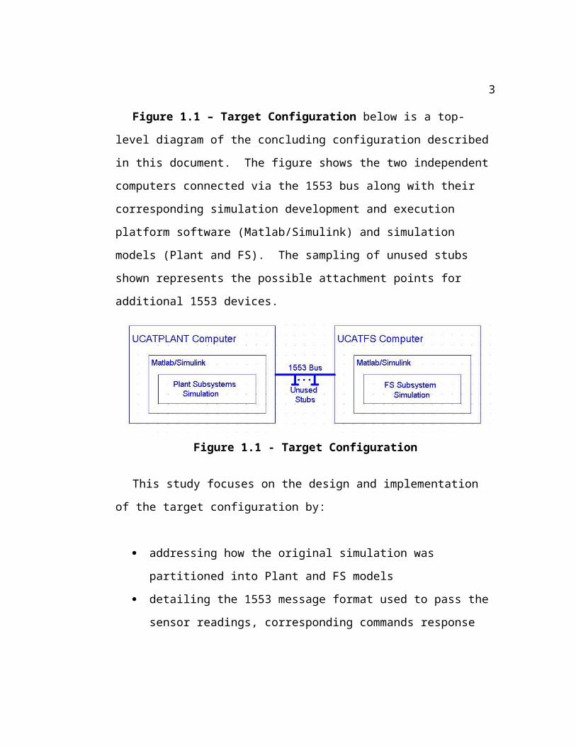
Figure 1.1 – Target Configuration below is a top-level diagram of the concluding configuration described in this document. The figure shows the two independent computers connected via the 1553 bus along with their corresponding simulation development and execution platform software (Matlab/Simulink) and simulation models (Plant and FS). The sampling of unused stubs shown represents the possible attachment points for additional 1553 devices.
Figure 1.1 - Target Configuration
This study focuses on the design and implementation of the target configuration by:
addressing how the original simulation was partitioned into Plant and FS models
detailing the 1553 message format used to pass the sensor readings, corresponding commands response and overhead (e.g.: count and checksum) data needed to maintain the simulations synchronized
describing the 1553 interface C code that allows the two simulations to communicate
3
describing how an operator would compile any changes to the interface code and execute the integrated simulation.
confirming the accuracy of the integrated model by comparing its results with the results of the original model
Finally, the major challenges that had to be overcome are detailed for the benefit of those faced with similar hurdles.
The original simulation selected for this study has a simulation time of 2200 seconds. This is the amount of real-time the mission analysts are interested in observing from time zero (launch) to intended orbit. In the original simulation the FS block is executed every 20 milliseconds (ms) of simulation time. Therefore, FS executes a total of (2,200,000 ms)/(20 ms) = 110,000 times plus one. One is added to 110,000 because the first FS block execution takes place at time zero. 110,001 represents the number of times the FS block processes a Plant or rocket set of sensor reading and returns the corresponding control and guidance commands to direct the actual ascent of the rocket from launch to intended orbit. Achieving these exchanges of readings and commands via the 1553 bus at the proper times during simulation execution was the main task realized by this study.
Consequently, mission analysts are now a step closer to being able to replace the FS block with an actual flight software computer. Such a configuration will allow them to more realistically test and checkout flight software changes and to verify the proper operation of Plant simulation blocks. In addition, they now have the option to test actual vehicle
4

hardware devices. They can physically add other rocket subsystems to the 1553 bus and integrate them into the simulation by writing interface C code similar to the one covered herein. Furthermore, this has been done using relatively inexpensive hardware and software (see Appendix A – Hardware and Software Prototype Description).
5

Page intentionally left blank.
6

Section 2 - Isolating FS Block
In order to partition the original model, the FS block was removed from the original simulation and inserted into a new, simplified model to run on a separate computer. The first step was to remove the FS block from the original model executing in the UCATPLANT computer, insert it into a newly created model (which I called the “FS” model) and save it (now without the FS block) as the new “Plant” model. The new Plant model will ultimately reside and execute on the UCATPLANT computer. The next steps were to move the new FS model file to the second computer (UCATFS) and to identify the FS block’s signal inputs and outputs whose values needed to traverse the 1553 bus. The last step was to add and connect the skeletal 1553 interface blocks to both models and confirm that both simulations could execute independently after the change. The text that follows will expand on each of these steps.
Removing the FS block from the original model was mostly trivial thanks to the capabilities of Simulink [8]. After loading the original model file, I found the FS block within the Control System block. The Control System block is itself composed of three blocks (see Figure 2.1 – Control System). The INERTIAL SENSORS block interfaces the sensors (gyros) to the FS block. I call this combination of gyro signals, a sensor reading. The FS block processes the sensor reading and generates the next set of
7

guidance commands and control calculations. Finally, the RELAYS & SWITCHES block energizes the appropriate actuator devices in response to the new commands and thus keeps the rocket on course.
8

To remove the FS block, I simply selected it and cut it. Then, I created a new model file and pasted the block into it. Finally, I saved the new model file with a new name (ucat_fs.mdl).
Figure 2.1 - Control System
To move the FS simulation to the UCATFS computer was also simple. I simply moved the newly created model file to a floppy disk, inserted the disk in the floppy drive of the UCATFS computer and copied the file to the system’s hard drive. Note that I was only able to do this because the resulting model file was small enough to fit into a floppy disk. I would have had to transfer a file of larger size using another mechanism. Before exiting the original model from where I had just removed the FS block on the UCATPLANT computer, I saved it to a new name (ucat_plant.mdl). The ucat_plant.mdl file represents the new Plant simulation that will execute on the UCATPLANT computer.
Expanding the FS block, now on the UCATFS computer, revealed that there are essentially four input signals to the block and one output signal from the block. These are shown in Table 2.1 – FS Input and Output Signals Description below along with the number of elements carried by each signal, their corresponding data types and number of bits as represented on Intel-based processors. Intel Pentium III processors were used
9

for UCATPLANT and UCATFS Central Processing Units (CPUs) (see Appendix A – Hardware and Software Prototype Description). Therefore, a total of 3(64) + 3(64) + 2(16) + 2(16) = 448 bits are inputs to the block and 36(16) = 576 bits are outputs from the block. Note that actual signal names used on the original simulation are not revealed here for proprietary reasons. Generic names are used instead.
Table 2.1 – FS Input and Output Signals Description
Table of FS Input and Output Signals Description
Name Type # of Elements
Data Type # of Bits each
Delta Theta Input 3 Double 64
Delta Velocity Input 3 Double 64
Gyro Input Input 2 Unsigned Short 16
Gnd Input Discretes Input 2 Unsigned Short 16
Commands Output 36 Unsigned Short 16
Since the FS block now resides on the UCATFS computer, the inputs or sensor readings (448 bits) must traverse the 1553 bus from the Plant simulation to the FS simulation. After the FS block processes these readings, the output or resulting commands (576 bits) must traverse the 1553 bus back from the FS simulation to the Plant simulation. This exchange of sensor and command data must happen at every 20 ms of Plant simulation time in order to keep the simulation moving forward.
Now that the signals that must traverse the 1553 bus and be processed by the isolated FS block had been identified, the next task was to develop the interfaces between the simulations and
10

the 1553 bus hardware to facilitate such a transfer. In order to communicate from a Simulink simulation to a physical 1553 interface board, a Simulink S-function can be used. The Simulink manual defines an S-function as “a computer language description of a Simulink block.” S-functions can be written in a multitude of computer languages including C [9]. Since SBS Technologies, the vendor of the 1553 interface boards I used publishes a C-based Integrated Avionics Library, I chose to write the S-functions using C [3].
The Matlab/Simulink product suite provides a wizard called the “S-function Builder” which allows for the skeletal creation of S-function blocks that can be added to simulations. While executing the wizard, you can specify the number and size of the block’s inputs and outputs. Once the wizard has completed, a Simulink block with the correct number of inputs and outputs is created. These inputs and outputs can then be connected to other simulation blocks. More importantly, a C code file is also generated with a set of empty functions called by Simulink at specific points during simulation execution. These functions are called “callback functions.” To complete the S-Function, you must choose which of these empty callback functions to populate and add the required functionality. Among others, there are three of these callback functions of paramount importance to this study. They are mdlInitializeConditions (called once at the beginning of the simulation), mdlOutputs (called at every execution time step), and mdlTerminate (called at the end of the simulation) [9].
11

I created two of these skeletal C code files or S-functions. One I called “ucatrt.c” to represent the 1553 interface between the Plant simulation and the 1553 bus interface board on the UCATPLANT computer. The other I called “ucatbc.c” to represent the 1553 interface between the FS simulation and the 1553 bus interface board on the UCATFS computer. The “rt” suffix stands for “remote terminal” and the “bc” suffix stands for “bus controller.” These terms are defined by the MIL-STD-1553 standard [1].
On the UCATFS computer, the FS block is connected to the ucatbc S-function block and it is through this S-function block that FS receives its input from the 1553 bus and transmits its output to the 1553 bus. FS and ucatbc were coupled because, as per one of the mission analysts, on the actual vehicle the flight software computer performs the bus controller functions. The rest of the 1553 subsystems on the vehicle are connected to the 1553 bus via remote terminals. Therefore, from a 1553 standpoint, the UCATPLANT computer behaves as an rt on the bus and the UCATFS computer behaves as the bc for the bus. This is as close a representation as I could make to the actual vehicle given the original simulation and the task to only isolate the FS block.
Back on the UCATPLANT computer, the INERTIAL SENSORS block provides the input (sensor reading) to the ucatrt S-function block for transmission to the 1553 bus. After the reading is processed by the now remote FS subsystem on the UCATFS computer, the ucatrt block on the UCATPLANT computer receives the corresponding FS commands response from the
12

1553 bus and passes them on to the RELAYS & SWITCHES block. See Figure 2.2 – 1553 Interfaces for clarification.
Figure 2.2 - 1553 InterfacesOn the UCATFS computer, the ucatbc S-function receives the
sensor readings from the 1553 bus. The FS block is a special kind of Simulink block called a “triggered function-call subsystem” or just a "triggered subsystem." As the name implies, the FS block behaves much like a standard function call in that it gets called (triggered) when needed and finishes by returning the result of its calculations to the entity that called it [8,9]. Since at this point no triggering code had yet been added to the ucatbc S-function block, the FS block was simply an idle block receiving inputs, doing nothing with them, doing no processing, and outputting nothing.
13

To conclude this section and to make sure that nothing else in the simulations had been adversely affected, I executed each simulation independently and verified that they ran. This small test was most important on the Plant side because of its large number of simulation blocks (the Plant simulation is composed of over 7000 Simulink blocks!). By performing this test, I made sure that no other Plant subsystem was broken by the removal of the FS block. Note that, at this point, even though the simulations ran, their results were inconclusive. This was expected since the sensor readings were simply being ignored by the ucatrt S-function block. No data was yet traversing the 1553 bus in either direction and the ucatbc S-function block was not triggering the FS block to process sensor readings or return corresponding guidance, navigation and control commands.
14

Section 3 – 1553 Transmissions
As previously outlined in Section 2 – Isolating FS Block, in order to integrate the 1553 bus, the original simulation had to be split up into two parts: Plant and FS. This separation introduced a serious challenge: how to synchronize two simultaneously running simulations? In this study, this synchronization is achieved by transmitting three 1553 messages every 20 milliseconds of Plant simulation time: one from Plant to FS with a new set of sensor readings and two from FS back to Plant with the corresponding commands response. In the 1553 messages, two 1553 words are used to keep track of the message exchange count being processed and the last word is used to store the messages’ checksum value. The following discussion focuses on the description of the message exchange that happens every 20 milliseconds of Plant simulation time and on the messages’ content and format (including message exchange count and checksum words).
Every 20 milliseconds of Plant simulation time a new sensor reading is available for transmission on its 1553 remote terminal (rt) transmit buffer. The FS simulation (running on the UCATFS computer) with its 1553 bus controller (bc) gets this sensor reading, processes it, and returns the corresponding commands response. Once the Plant receives the commands it is expecting,
15

it proceeds with the simulation. This exchange of sensor reading and corresponding commands response continues at every 20 milliseconds of Plant simulation time until the Plant simulation is finished. It must be noted that the Plant can go through multiple simulation steps between exchanges.
16

As discussed in Section 2 – Isolating FS Block, 448 bits are needed to transmit the sensor readings. The 1553 standard allows for a maximum of 32 16-bit data words per message or packet [1]. Thus a total of 512 data bits can be transmitted per message. I used one message to get the sensor readings from the Plant simulation to the FS simulation. The table below outlines the sensor reading message format including overhead words.
Table 3.1 – Sensor Reading Message Format
Table of Sensor Reading Message Format
d0 d1 d2 d3 d4 d5 d6 d7
d8 d9 d10 d11 d12 d13 d14 d15
d16 d17 d18 d19 d20 d21 d22 d23
d24 d25 d26 d27 u cnt0 cnt1 csum
Words d0 thru d23 represent the words needed to transmit the six doubles (four 1553 words or 64 bits are required per double), while d24 thru d27 represent the words needed to transmit the remaining four shorts (one 1553 word or 16 bits are required per short). The u word is “unused” or reserved for future use. The words cnt0 and cnt1 are used to transmit the exchange count number. Finally, the csum word is used to transmit the message checksum value.
Note that I’ve allocated 32 bits (two 1553 words) to the exchange count because a single 16-bit word is not enough to keep track of the maximum count of 110,001 (the latter number
17

of exchanges was derived in Section 1 – Introduction). A single 16-bit word would permit only 216 or 65536 message exchanges, while 32 bits (two 1553 16-bit words) would permit a maximum of 232 or 4,294,967,296 exchanges. The latter allows for the number of exchanges to support this or similar simulations (assuming an exchange is taken every 20 ms) with a maximum runtime of (4,294,967,296 exchanges * 20 ms) / (1,000) = 85,899,346 seconds or 23,861 hours (approximately 994 days). Therefore, all rocket launches can be simulated without the number of message exchanges growing beyond the allocated two 1553 words. Furthermore, the unused or reserved 1553 word in the message can be incorporated into the solution if the required number of exchanges has to be expanded for some unexpected reason.
The checksum word (csum) field stores the add-without-carry of the first 31 words in the message. The last word (word 32) is reserved for the checksum word itself and is therefore not included in the calculation. I decided to use this scheme because it is simple to implement in C and it is also used by the International Space Station (ISS) to detect transmission errors [1]. The calculation is straightforward and can be done in any programming language with support for the binary “x-or” operation. Figure 3.1 – Add-without-carry Checksum Calculation below shows some code that will accomplish this task in C using the “^” (x-or) operator. Note that BUF_SIZE is previously declared to be equal to 32 (the maximum number of data words that can be transmitted per 1553 message [1]), and that rBuffer is an array containing the 1553 words of the
18

message from which to calculate the checksum value. The resulting csum value is stored in the checksum field of the message (last word).
19

/*Calculate the checksum that "should have" been received.*/
csum = 0xFFFF;
for (i = 0; i < (BUF_SIZE - 1); i++)
{
csum = csum ^ rBuffer[i];
}
Figure 3.1 – Add-without-carry Checksum Calculation
The Section 2 – Isolating FS Block section states that 576 bits are needed to transmit the commands response. Since this is larger than the 512 bits maximum allowed by a 1553 message, I used two messages to send the command responses from the FS to the Plant simulation. Table 3.2 – 1st Commands Response Message Format below outlines the first command responses message format including the overhead words (cnt0, cnt1, and csum).
Table 3.2 – 1st Commands Response Message Format
Table of 1st Commands Response Message Format
d0 d1 d2 d3 d4 d5 d6 d7
d8 d9 d10 d11 d12 d13 d14 d15
d16 d17 u u u u u u
u u u u u cnt0 cnt1 csum
Words d0 thru d17 represent the words needed to transmit the first 18 shorts or commands. Recall that 36 commands (represented as a 16-bit short value or single 1553 word each)
20

are returned to the Plant simulation from the FS simulation in response to the last sensor reading. This happens every 20 milliseconds of Plant simulation time. As shown on Table 3.1 - Sensor Reading Message Format, the u words are “unused”, the cnt0 and cnt1 words are used to transmit the exchange count
number, and the csum word is used to transmit the message checksum value.
Finally, Table 3.3 – 2nd Command Responses Message Format below describes the format of the message with the last 18 command responses. u, cnt0, cnt1, and csum are as previously described. Note that cnt0 and cnt1 words must be the same on the one sensor reading and the two commands response messages before the S-functions consider the exchange to be complete.
Table 3.3 – 2nd Commands Response Message Format
Table of 2nd Commands Response Message Format
d18 d19 d20 d21 d22 d23 d24 d25
d26 d27 d28 d29 d30 d31 d32 d33
d34 d35 u u u u u u
u u u u u cnt0 cnt1 csum
To conclude this section, I would like to summarize what transpires at every 20 milliseconds of Plant simulation time with regards to this messages exchange. Refer to the figure below for clarification of the following discussion.
21

Figure 3.2 – 1553 Messages
Every 20 ms, the Plant simulation will load its 1553 transmit buffer with a new set of rocket sensor readings and wait for the corresponding commands response. The FS simulation constantly or, as fast as it can, reads the Plant’s transmit buffer by requesting a message like the one described in Table 3.1 – Sensor Reading Message Format, but does not process the reading unless it is the one expected. The FS simulation stores the count or number of the last reading it processed plus one and continues to poll the Plant's transmit buffer until the new count
22

arrives. The simulation determines whether the reading is the one expected by concatenating the hexadecimal values in cnt0 and cnt1 and comparing the resulting integer value with the one it previously processed plus one. If the check results in a “true” condition, then FS has received a new sensor reading to be processed. The FS simulation processes the reading by triggering the flight software block and sending the corresponding commands response as two 1553 messages back to the Plant simulation. The formats of these two messages are described in tables 3.2 and 3.3. The Plant simulation in turn comes out of its wait loop when the two expected commands response messages are received and proceeds until the next 20 millisecond simulation time step. The reason why the FS simulation must continuously poll the Plant’s transmit buffer for the next sensor reading is to keep the Plant simulation executing as fast as possible. By allowing the Plant to execute as fast as possible, the integrated simulation can be made to execute near to or faster than real-time. Running faster than real-time is desired to facilitate multiple analysis runs in the same amount of time.
23

Page intentionally left blank.
24

Section 4 – S-function Code
In Section 2 – Isolating FS Block I introduced two Simulink S-functions that represent the interfaces between the Plant and FS simulations and the respective 1553 boards: ucatbc.c for the FS simulation and ucatrt.c for the Plant simulation. The ucatbc.c S-function plays the role of the bus controller (bc) while ucatrt.c plays the role of the remote terminal (rt). These S-functions are made up of callback functions executed by Simulink at specific points during simulation execution. For the purposes of this discussion, only three of these callback functions are covered in detail here: mdlInitializeConditions, mdlInitializeSampleTimes, mdlOutputs, and mdlTerminate. They are responsible for facilitating the exchange of messages across the 1553 bus and thus for the synchronization of the two simulations. Simulink calls mdlInitializeConditions and mdlInitializeSampleTimes at the beginning of the simulation during the initialization phase, mdlOutputs at every time step, and mdlTerminate at the end of the simulation (See Figure 4.1 – Callback Interactions) [9].
This section will focus on the listing and description of the source code contents of these three callback functions. In addition, I will discuss how the S-functions are compiled to generate the required dynamic link libraries (DLLs) called by Simulink. DLLs are required by this study because both UCATFS
25

and UCATPLANT computers use the Microsoft Windows 2000 operating system (see Appendix A - Hardware and Software Prototype Description). Once compiled, the ucatbc.c and ucatrt.c S-functions generate ucatbc.dll and ucatrt.dll respectively.
26

Figure 4.1 – Callback Interactions
The ucatbc.c S-function is responsible for managing all the communications on the bus. Note that the exchange of sensor reading and corresponding commands response messages does not take place at every FS simulation time step. Instead, it happens whenever the ucatbc.c S-function detects that ucatrt.c is ready with a new sensor reading and when the Plant is not busy processing its current simulation time step. This is the same as saying that the exchange of messages happens at every 20 milliseconds of Plant simulation time. ucatbc.c is also responsible for initializing and terminating the 1553 board device on the UCATFS computer at the beginning and at the end of the FS simulation respectively.
The bus controller (bc) operation is directed by a data structure composed of one or more program chains (see Figure 4.2 – BC Program). Each chain consists of a linked-list of control blocks with instructions for the bus controller to perform and how to perform them. In this study, the bus controller
27

program is composed of two chains. I called the first chain the “get reading” (GR) chain. The GR chain has a single control block whose main function is to get the sensor-reading message from the Plant simulation. I called the second chain the “send response” (SR) chain. The SR chain has two control blocks (SR1 and SR2). The SR control blocks transmit the two messages containing the FS simulation’s commands response back to the Plant. For each of the control blocks, one or more data buffers can be allocated. The number of buffers allocated is limited only by the physical memory installed on the board [5]. In this case, only one memory buffer of 32 1553-words is needed per control block. For a visual description of the tasks performed by both S-functions, see the 1553 S-function Interface Full System Flowchart in Appendix E at the end of this document.
Figure 4.2 – BC Program
The outline that follows shows the main tasks the ucatbc.c S-function performs. The subsequent table (Table 4.1 – ucatbc.c Source Code Listing) shows the relevant source code followed
28

by any clarifying remarks that the source comments fail to adequately address.
ucatbc.c main tasks:1. Declarations
a. 1553-specificb. UCAT-specific
29

2. At initialization (mdlInitializeConditions):a. Initialize first count expectedb. Initialize devicec. Initialize BC program chaind. Start input/output
3. Initialize sample times (mdlInitializeSampleTimes)4. At each simulation time step (mdlOutputs):
a. Local function variable declarationsb. Wait while rt is busyc. Read rt message (sensor reading) from firmware
receive buffer into application receive bufferd. Read checksum and count receivede. If the count received is the count expected, and if
there was no transmission error detected, process the new reading:
i. Output the reading to the FS blockii. Trigger the FS block to begin processingiii. Populate 1st transmit buffer with the 1st set of
18 commands returned by the FS blockiv. Add count and checksum to application
bufferv. Write buffer to 1st firmware transmit buffervi. Populate 2nd transmit buffer with the 2nd set
of 18 commands returned by the FS blockvii. Add count and checksum (after calculation)
to the bufferviii. Write buffer to 2nd firmware transmit buffer
30

ix. Wait until the bc chain responsible for getting the sensor reading has completed before loading the one to return the corresponding commands response
x. Increment the count expected to wait for next reading
5. At termination (mdlTerminate):a. Stop BC programb. Stop input/outputc. Close device
31

Table 4.1 – ucatbc.c Partial Source Code Listing
Table of ucatbc.c Partial Source Code Listing
1.a - Source Code
/*@@@@@ Begin global 1553 declarations to be used by multiple functions. @@@@@*/
#include "1553_inc.h"#define DEV_NUM 1 /* Always "1", we only have a single PCI card. */#define IQ_LENGTH 4 /* Interrupt queue length – minimum value is 4. */#define BMQ_LENGTH 1000 /* Bus monitoring queue length. */#define BUF_SIZE 32 /* 1553 messages can store 32 16-bit words. */
SBS_EXCEPTION status; /* Used to store returning SUCCESS or FAILURE. */int wc; /* Stores returning word count when reading/writing message buffers. */
/* Define the BC program chains 1. GR (Get Reading) 2. SR (Send Command Response) - Chain 1 gets vehicle sensor readings. - Chain 2 sends the corresponding command responses. */#define GR_ID 1 /* Link ID for Get Reading link */#define SR_ID 2 /* Link ID for Send Command Response link */SBS_CHAIN_LINK_INFO GR = {RTBC,1,1,1,BUF_SIZE,0,0x0,FALSE,FALSE, 0,0,0,1,NULL,0,0,0,0,0,0,0,0,0,0,0};SBS_CHAIN_LINK_INFO SR1 = {BCRT,2,1,2,BUF_SIZE,0,0x0,FALSE,FALSE, 0,0,0,1,NULL,0,0,0,0,0,0,0,0,0,0,0};SBS_CHAIN_LINK_INFO SR2 = {BCRT,2,1,3,BUF_SIZE,0,0x0,FALSE,FALSE, 0,0,0,1,NULL,0,0,0,0,0,0,0,0,0,0,0};
/*@@@@@ End global 1553 declarations. @@@@@*/
32

Table of ucatbc.c Partial Source Code Listing (continued)
1.a – RemarksThe GR chain declaration represents the bus controller command data structure definition to get the sensor reading. Of significance are the following elements listed by their corresponding index:
[0] RTBC – message type [1] 1 – chain id [2] 1 – from remote terminal 1 [3] 1 – from sub-address 1 [4] BUF_SIZE – size of message in 1553 words [5] 1 – to link id (BC receive buffer) [7] FALSE – loop flag (don’t loop)[12] 1 – number of buffers
Note that the command/message is a remote terminal to bus controller message (RTBC). That it is the first chain in the program instructing that the message be transmitted from rt1, sa1 as a 32-word message and be received on the bc link id 1 buffer. The instruction does not loop (that is, it executes only once every time the chain is loaded to execute). Finally, the instruction allocates a single memory buffer on the board for the message to receive the sensor reading.
The SR chain with SR1 and SR2 control blocks are similar except that they cause the transmission of BC to RT messages (BCRT). They represent the second chain in the program and transmit the two commands response messages destined for rt1, sa2 and rt1, sa3 receive buffers respectively on the Plant simulation.
33

Table of ucatbc.c Partial Source Code Listing (continued)
1.b – Source Code/*@@@@@ Begin global UCAT declarations. @@@@@*/
/* Define size of input/output signals to/from 1553 subsystem block. */ #define CMD_SIZE 36 /* Commands – output */#define DT_SIZE 3 /* Delta Theta – input */#define DV_SIZE 3 /* Delta Velocity - input */#define GI_SIZE 3 /* Gyro Input – input */#define GID_SIZE 2 /* Gyro Input Discrete – input */
#define RESET 0x0000 /* Used to reset 1553 words on buffers. */#define WORDS_PER_DOUBLE 4 /* Four 1553 words to store one double value. */#define MAX_STEPS 110001 /* Maximum number of RT simulation steps. Used to keep the BC from polling after the RT simulation ends. Stops the BC sim. (2200sec * 50 samples/sec = 110000 samples, plus 1 because we start at time zero) */
/* Define important message indices. */#define CMD_DATA_END 17 /* End of command words for SR1 and SR2 messages. */#define COUNT_START 29 /* Exchange count words begin at word index 29. */ #define COUNT_END 30 /* Exchange count words end at word index 30. */#define CSUM_IDX 31 /* Word index where checksum field is expected. */
/* To keep track of exchange counts. */int xCntExpected;
/*@@@@@ End UCAT specific declarations. @@@@@*/
2.a – Source Code/** * Function: mdlInitializeConditions * Abstract: * Initializes 1553 card and variables. * Defines the BC chain program. * Starts the IO bus operation. * Clears initial application and firmware buffers. */#define MDL_INITIALIZE_CONDITIONSstatic void mdlInitializeConditions(SimStruct *S){ /* Initialize first count expected. */ xCntExpected = 0;
34

Table of ucatbc.c Partial Source Code Listing (continued)
2.a – RemarksSince mdlInitializeConditions is called once at the beginning of the simulation, I used this opportunity to initialize the reading count variable (xCntExpected).
2.b – Source Code /* Initialize the 1553 board device. */ if (sbs_init_device(DEV_NUM, IQ_LENGTH, BMQ_LENGTH, FROM_FILE) == FAILURE) { ssPrintf("Failed initializing the device! %s\n", sbs_read_error()); ssSetStopRequested(S, true); return; }
2.b – RemarksNote that the SBS Integrated Avionics Library requires IQ_LENGTH and BMQ_LENGTH entries when initializing the device, but that I leave them with their default values since they are sufficient for this application.
The parameters to sbs_init_device are the device number (DEV_NUM - always 1 in our case since we only have a single board), the interrupt queue length (IQ_LENGTH), the bus-monitoring queue length (BMQ_LENGTH), and the firmware source (FROM_FILE - read in from a disk file in this case).
The ssPrintf function is a Simulink function that outputs a message to the Matlab command console. The ssSetStopRequested function instructs Simulink to continue processing the current simulation step, but to terminate the simulation thereafter.
2.c – Source Code /* Initialize/build BC program chain. */ status = SUCCESS; status *= m1553_add_link_to_chain(DEV_NUM, &GR); status *= m1553_add_link_to_chain(DEV_NUM, &SR1); status *= m1553_add_link_to_chain(DEV_NUM, &SR2); if (status == FAILURE) { ssPrintf("Failed to add links to BC program chain! %s\n", sbs_read_error()); ssSetStopRequested(S, true); return; }
2.c – RemarksThe m1553_add_link_to_chain function copies the previously defined GR, SR1 and SR2 chain link data into the board’s firmware.
35

Table of ucatbc.c Partial Source Code Listing (continued)
2.d – Source Code /* Start 1553 bus operation. */ status = sbs_start_io(DEV_NUM); if (status == FAILURE) { ssPrintf("Failed starting io bus operation! %s\n", sbs_read_error()); ssSetStopRequested(S, true); return; }}
2.d – RemarksThe function sbs_start_io starts input/output or bus processing on the bus controller just loaded into firmware.
3. – Source Code/** * Function: mdlInitializeSampleTimes * Abstract: * Specify the sample time. Inherited in this case. */static void mdlInitializeSampleTimes(SimStruct *S){ ssSetCallSystemOutput(S, 0); ssSetSampleTime(S, 0, INHERITED_SAMPLE_TIME); ssSetOffsetTime(S, 0, 0.0);}
3. – RemarksThe "ssSetCallSystemOutput" line specifies that output port "0" is one to issue the function call to the FS block triggered subsystem. It is through this output line that the FS block is triggered to process the sensor reading and generate the next set of guidance commands.
By setting the third parameter of the ssSetSampleTime Simulink function to INHERITED_SAMPLE_TIME, I instruct Simulink to execute the S-function block as fast as the system allows. Normally, an inherited sample time means that the block is driven by either the driving or destination block. But, since in this case, the driving and destination blocks are one and the same (the FS block) and since the FS block is a triggered subsystem, the 1553 S-function is being driven by the fastest sample time possible. This means that the S-function block will execute as fast as the system allows.
36

Table of ucatbc.c Partial Source Code Listing (continued)
4.a – Source Code/** * Function: mdlOutputs * Abstract: * Check to see if a new set of sensor readings is * available on the Plant sim. This is done by * reading a message from rt1sa1t while it is not * busy and checking against the next expected count. * * Once a reading with the expected count is received, * trigger the FS block to calculate the corresponding * commands and send them back to the Plant’s receive * buffers (rt1sa2r and rt1sa3r). */static void mdlOutputs(SimStruct *S, int_T tid){ const real_T *u0 = (const real_T*) ssGetInputPortSignal(S,0); const real_T *u1 = (const real_T*) ssGetInputPortSignal(S,1); boolean_T *y0 = (boolean_T *) ssGetOutputPortRealSignal(S,0); real_T *y1 = (real_T *) ssGetOutputPortRealSignal(S,1);
int i, j; /* Used as indices into arrays. */ int iIdx; /* Block input index */ int oIdx; /* Block output index */ int bIdx; /* Buffer index */ int xCntRcvd; /* Stores the exchange count received from Plant sim. */ SBS16 *ptr; /* Used to build doubles from four 16-bit 1553 words. */ SBS16 grCSumRcv; /* Stores the checksu received on message from Plant sim. */ SBS16 grCSum; /* Stores calculated checksum for received sensor message. */ SBS16 sr1CSum; /* Stores calculated checksum for 1st FS command message. */ SBS16 sr2CSum; /* Stores calculated checksum for 2nd FS command message. */ SBS_STATUS_BLOCK_TYPE linkStatus; /* Used to check the Plant’s (rt) busy bit. */ SBS16 rBuffer[BUF_SIZE]; /* Receive buffer for GR (Get Reading) chain link. */ SBS16 t1Buffer[BUF_SIZE]; /* Transmit buffer 1 for SR1 - 1st
part of response. */ SBS16 t2Buffer[BUF_SIZE]; /* Transmit buffer 2 for SR2 - 2nd
part of response. */
4.a – Remarksu0 and u1 represent the input signals to the S-function block while y0 and y1 represent the output signals.
37

Table of ucatbc.c Partial Source Code Listing (continued)
4.b – Source Code /* Stop the bus controller when all Plant sim steps have been completed. Finish the last step before stopping. */ if (xCntExpected >= MAX_STEPS) ssSetStopRequested(S, true);
/* Wait while RT is busy. */ do { /* Make sure the BC program has completed before calling it again. */ while (LL_get_ram(DEV_NUM, SBS_BCCPTR) != (SBS16) 0) {}
/* Start the BC program chain to get reading from rt1sa1t. */ status = SUCCESS; status *= m1553_load_chain(DEV_NUM, 1); if (status == FAILURE) { ssPrintf("Failed while loading BC GR chain! %s\n", sbs_read_error()); ssSetStopRequested(S, true); return; }
/* Get the status of the RTBC instruction until it succeeds. */ while (m1553_read_link_status(DEV_NUM, GR.link_id, linkStatus) == FAILURE) {} } while(((SBS_STATUS_RESPONSE_TYPE *) linkStatus)->bits.busy == 1);
4.b – RemarksWhen the next count expected is equal to MAX_STEPS, the Plant simulation is in its last step. Stop the FS simulation after completing this step.
SBS_BCCPTR is the current bus controller program block pointer. When it becomes zero, the BC program has finished executing. Note that the m1553_load_chain function is responsible for starting the BC program execution. Do not start the program until the previous one has finished executing.
The inner while loop uses the m1553_read_link_status function to get the status of the previous message received from the Plant. The status returned contains the state of the remote terminal’s busy-bit. The outer do-while loop continues to execute as long as the Plant’s simulation returns a status of busy running its simulation step.
38

Table of ucatbc.c Partial Source Code Listing (continued)
4.c – Source Code /* Busy bit is no longer set, RT is ready. Read firmware receive buffer. */ grCSumRcv = 0x0000; wc = 0; wc = m1553_read_link_data(DEV_NUM, GR.link_id, GR.buff_id[0], rBuffer); if (wc == 0) { ssPrintf("Failed to get sensor reading from rt1sa1t! Stopping sim...\n"); ssSetStopRequested(S, true); return; }
4.c – RemarksOnce the Plant’s simulation is no longer busy, the sensor reading message is transmitted from remote terminal 1, sub-address 1 transmit buffer (rt1sa1t) on the Plant side to the BC’s get reading (GR) chain link receive buffer on the FS side. Note that only a single buffer was allocated when GR was defined, thus index 0 is used for GR.buff_id.
The m1553_read_link_data function loads the reading last received into the application rBuffer.
4.d – Source Code /* Read the checksum word just received. */ grCSumRcv = rBuffer[CSUM_IDX]; /* Calculate the checksum that "should have" been received. */ grCSum = 0xFFFF; for (i = 0; i < (BUF_SIZE - 1); i++) { grCSum = grCSum ^ rBuffer[i]; } /* Read the new count received. */ ptr = (SBS16 *) &xCntRcvd; ptr[1] = rBuffer[COUNT_START]; ptr[0] = rBuffer[COUNT_END];
39

Table of ucatbc.c Partial Source Code Listing (continued)
4.e.i – Source Code /* If BC gets the expected reading, process it. Otherwise, move to the next sim step and try again. The expected reading will have arrived when next expected count (xCntExpected) words are received on link buffer (GR). If so, trigger FS block and process the data. Once the sensor data count (xCntRcvd) and checksum word are the ones we are expecting, forward the reading to the FS block and trigger it to process the reading and to generate the response set of commands. */ if (((xCntRcvd == xCntExpected) && (grCSumRcv == grCSum))) { oIdx = 0; /* Output Index */ bIdx = 0; /* Buffer Index */ for (i = 0; i < DT_SIZE; i++) { ptr = (SBS16 *) &y1[oIdx++]; for (j = 0; j < WORDS_PER_DOUBLE; j++) { ptr[j] = rBuffer[bIdx++]; } } for (i = 0; i < DV_SIZE; i++) { ptr = (SBS16 *) &y1[oIdx++]; for (j = 0; j < WORDS_PER_DOUBLE; j++) { ptr[j] = rBuffer[bIdx++]; } } /* Note, elements 2 and 3 only */ for (i = 1; i < GI_SIZE; i++) { y1[oIdx++] = rBuffer[bIdx++]; } /* Note, elements 0 and 1 only */ for (i = 0; i < GID_SIZE; i++) { y1[oIdx++] = rBuffer[bIdx++]; }
4.e.i – RemarksoIdx variable steps through the elements of the output signal y1, while bIdx variable steps through the 1553 words in the application buffer(s).
40

Table of ucatbc.c Partial Source Code Listing (continued)
4.e.ii – Source Code /* Call FS triggered subsystem to process sensor reading. */ if (!ssCallSystemWithTid(S, 0, tid)) { ssPrintf("Failed triggering the FS subsystem to run!\n"); ssSetStopRequested(S, true); return; } else {
4.e.iii – Source Code /* After successful execution of the FS triggered subsystem, control returns here. The output of the FS block should now be waiting to be read on the input to this block. Populate the transmit buffers with command data, count number and checksum.
Load transmit link buffers (SR1 and SR2). Use xCntRcvd so that the sensor data and command response have the same count number. */
/* Load SR1 application buffer first. */ iIdx = 0; /* Reset to begin reading FS response from block's input. */ bIdx = 0; /* Reset to begin loading buffer. */ /* First 18 words from FS result. */ for (i = 0; i <= CMD_DATA_END; i++) { t1Buffer[bIdx++] = (SBS16) u0[iIdx++]; }
4.e.iv – Source Code /* Move buffer index to count start word. */ bIdx = COUNT_START; ptr = (SBS16 *) &xCntRcvd; /* ptr[1] before ptr[0] because of Little Endian. */ t1Buffer[bIdx++] = ptr[1]; t1Buffer[bIdx++] = ptr[0]; /* Generate checksum for SR1 transmit buffer. Note "(BUF_SIZE - 1)" is used because checksum field itself is not included in the calculation. */ sr1CSum = 0xFFFF; for (i = 0; i < (BUF_SIZE - 1); i++) { sr1CSum = sr1CSum ^ t1Buffer[i]; } /* Store checksum word. */ t1Buffer[CSUM_IDX] = (SBS16) sr1CSum;
41

Table of ucatbc.c Partial Source Code Listing (continued)
4.e.v – Source Code /* Write to SR1 firmware link buffer. */ wc = 0; wc = m1553_write_link_data(DEV_NUM, SR1.link_id, SR1.buff_id[0], t1Buffer); if (wc == 0) { ssPrintf("Failed to write 1st part of FS response! Stopping sim...\n"); ssSetStopRequested(S, true); return; }
4.e.vi – Source Code /* Load SR2 application buffer: */ bIdx = 0; /* Reset to begin loading buffer. */ /* Last 18 words from FS result. */ for (i = 0; i <= CMD_DATA_END; i++) { t2Buffer[bIdx++] = (SBS16) u0[iIdx++]; }
4.e.vii – Source Code /* Move buffer index to count start word. */ bIdx = COUNT_START; ptr = (SBS16 *) &xCntRcvd; /* ptr[1] before ptr[0] because of Little Endian. */ t2Buffer[bIdx++] = ptr[1]; t2Buffer[bIdx++] = ptr[0]; /* Generate checksum for SR2 transmit buffer. Note "(BUF_SIZE - 1)" is used because checksum field itself is not included in the calculation. */ sr2CSum = 0xFFFF; for (i = 0; i < (BUF_SIZE - 1); i++) { sr2CSum = sr2CSum ^ t2Buffer[i]; } /* Store checksum word. */ t2Buffer[CSUM_IDX] = (SBS16) sr2CSum;
4.e.viii – Source Code /* Write to SR2 firmware link buffer. */ wc = 0; wc = m1553_write_link_data(DEV_NUM, SR2.link_id, SR2.buff_id[0], t2Buffer); if (wc == 0) { ssPrintf("Failed to write 2nd part of FS response! Stopping sim...\n"); ssSetStopRequested(S, true); return; }
42

Table of ucatbc.c Partial Source Code Listing (continued)
4.e.ix – Source Code /* Make sure that the chain to get reading has completed executing before loading the one to transmit the corresponding response. */ while (LL_get_ram(DEV_NUM, SBS_BCCPTR) != (SBS16) 0) {}
/* Start the BC program chain to send the response to rt1sa2r and rt1sa3r. */ status = SUCCESS; status *= m1553_load_chain(DEV_NUM, 2); if (status == FAILURE) { ssPrintf("Failed while loading SR chain! %s\n", sbs_read_error()); ssSetStopRequested(S, true); return; }
4.e.x – Source Code /* Increment xCntExpected to be used on next sim step. */ xCntExpected++; } }
ucatbc_Outputs_wrapper(u0,u1,y0,y1);}
5.a – Source Code/** * Function: mdlTerminate * Abstract: * Stop program chain, bus IO and ABI-PCI-1 device. */static void mdlTerminate(SimStruct *S){ m1553_stop_chain(DEV_NUM);5.b – Source Code sbs_stop_io(DEV_NUM);5.c – Source Code sbs_close_device(DEV_NUM);}
5.a,b,c – RemarksThe mdlTerminate callback function is forcibly called whenever and however the simulation ends to make sure that the 1553 board is not left open (even if errors were encountered during the simulation execution). Adding the SS_OPTION_CALL_TERMINATE_ON_EXIT option to the Simulink ssSetOptions function call in the mdlInitializeSizes callback forces the latter to happen. For clarity purposes, the listing of mdlInitializeSizes has not been included in this section. The full listing of the ucatbc.c S-function is provided in Appendix B of this document.
43

On the UCATPLANT computer, the 1553 interface role is played by the ucatrt.c S-function. In general, its main job is to get a new sensor reading every 20 ms of simulation time from the INERTIAL SENSORS bl0ck and to store it in its 1553 transmit buffer. Thereafter, it waits for the corresponding commands response from the FS simulation and forwards them to the RELAYS & SWITCHES block. Similar to the ucatbc.c S-function, ucatrt.c initializes the 1553 board device on the UCATPLANT computer at the beginning of the simulation and closes the device at the end.
The outline that follows shows the main tasks the ucatrt.c S-function performs. The subsequent table (Table 4.2 – ucatrt.c Source Code Listing) shows relevant source code along with any clarifying remarks that the source code comments fail to adequately address.
ucatrt.c main tasks:1. Declarations
a. 1553-specificb. UCAT-specific
2. At initialization (mdlInitializeConditions):a. Initialize first countsb. Initialize devicec. Define remote terminal sub-addressesd. Start input/output
3. Initialize sample times (mdlInitializeSampleTimes)4. Every 20 milliseconds of simulation time (mdlOutputs):
a. Local function variable declarationsb. Read sensor data and store in application buffer
44

c. Add new count and checksum to application bufferd. Write application buffer to firmware transmit
buffere. Clear busy-bit to signal new sensor reading
available for processing to bus controller in FS simulation
f. Wait until the corresponding commands response to the latest reading arrives from FS simulation
g. Set the busy-bit to signal to the bus controller that it must stop requesting new readings until the next one is ready
h. Forward the commands response to the next simulation block (RELAYS & SWITCHES)
i. Increment count transmitted to prepare for next sensor reading
5. At termination (mdlTerminate):a. Stop input/outputb. Close device
45

Table 4.2 – ucatrt.c Partial Source Code Listing
Table of ucatrt.c Partial Source Code Listing
1.a – Source Code/*@@@@@ Begin global 1553 declarations to be used by multiple functions. @@@@@*/
#include "1553_inc.h"#define DEV_NUM 1 /* Always "1", we only have a single PCI card. */#define IQ_LENGTH 4 /* Interrupt queue length – minimum value is 4. */#define BMQ_LENGTH 1000 /* Bus monitoring queue length. */#define BUF_SIZE 32 /* Buffers store 32 16-bit words. */
SBS_EXCEPTION status; /* Used to store returning SUCCESS or FAILURE. */int wc; /* Stores returning word count when reading/writing message buffers. */
/* RT/SA's to be allocated: SR (Send Reading) CR (Receive Command Response) */SBS_SA_INFO_TYPE SR = {1, 1, SBS_XMIT, 0, 1, NULL, 0};SBS_SA_INFO_TYPE CR1 = {1, 2, SBS_RCV, 0, 1, NULL, 0};SBS_SA_INFO_TYPE CR2 = {1, 3, SBS_RCV, 0, 1, NULL, 0};
/*@@@@@ End global 1553 declarations. @@@@@*/
1.a – RemarksIn order to program the remote terminal, you need to determine the number of transmit and receive buffers that will be needed by the application. The SBS_SA_INFO_TYPE declarations detail how the remote terminal (rt) data structures should be setup. The SR data structure defines the buffer from which the sensor reading is transmitted to the FS simulation. CR1 and CR2 data structures define the buffers where the commands response messages from the FS simulation are received. Of significance to this application are the following SR data structure elements listed by their corresponding index:
[0] 1 – remote terminal (rt1)[1] 1 – sub-address number (sa1)[2] SBS_XMIT – for transmit[4] 1 – numbers of buffers allocated to sub-address (sa)
Therefore, SR declares a sub-address buffer number 1 for remote terminal 1 for transmission purposes (rt1sa1t). Similarly, CR1 and CR2 are declared for remote terminal 1, with sub-addresses 2 and 3 respectively, but for reception purposes (rt1sa2r and rt1sa3r). Both allocate a single buffer in the board’s firmware.
46

Table of ucatrt.c Partial Source Code Listing (continued)
1.b – Source Code/*@@@@@ Begin global UCAT declarations. @@@@@*/
/* Define the size of input/output signals to/from 1553 subsystem block. */#define CMD_SIZE 36 /* Commands – output */#define DT_SIZE 3 /* Delta Theta – input */#define DV_SIZE 3 /* Delta Velocity – input */#define GI_SIZE 3 /* Gyro Input – input */#define GID_SIZE 2 /* Gyro Input Discrete – input */
#define RESET 0x0000 /* Used to reset 1553 words on buffers. */#define WORDS_PER_DOUBLE 4 /* Four 1553 words to store one double value. */#define WAIT_CNT 2000000 /* Counter to trigger sim stop when exhausted. Can be increased to allow the operator more time to start the FS simulation. */
/* Define important message indices. */#define CMD_DATA_END 17 /* End of command words for CR1 and CR2 buffers. */#define COUNT_START 29 /* Exchange count words begins at word 29. */#define COUNT_END 30 /* Exchange count words ends at word 30. */#define CSUM_IDX 31 /* Word index where checksum field is expected. */
/* To keep track of the number of sensor readings transmitted to UCATFS. */int xCntTransmitted;
/* Used to display startup messages to operator. */int cnt0;int cnt1;
/*@@@@@ End UCAT specific declarations. @@@@@*/
1.b - RemarksOnce the remote terminal (rt) transmit buffer is loaded, the rt must wait for the corresponding response. While rt waits, the WAIT_CNT is decremented. Once WAIT_CNT is exhausted, rt gives up the wait and exits the simulation with an error message. Initially, this wait period is used to allow the operator time to start the FS simulation. cnt0 indicates that the FS simulation should be started, while cnt1 indicates that the synchronized simulations have begun.
47

Table of ucatrt.c Partial Source Code Listing (continued)
2.a – Source Code/** * Function: mdlInitializeConditions * Abstract: * Initializes 1553 card and variables. * Defines the RT sub-address buffers. * Starts the IO bus operation. */#define MDL_INITIALIZE_CONDITIONSstatic void mdlInitializeConditions(SimStruct *S){ /* Initialize exchange count. */ xCntTransmitted = 0;
/* Initialize counts for startup messages. */ cnt0 = 0; cnt1 = 0;
2.a – RemarksSince mdlInitializeConditions is called once at the beginning of the simulation, I used this opportunity to initialize the count variables (xCntTransmitted, cnt0 and cnt1).
As explained earlier, cnt0 and cnt1 are used to display user messages to startup the synchronized simulations.
2.b – Source Code /* Initialize the device. */ if (sbs_init_device(DEV_NUM, IQ_LENGTH, BMQ_LENGTH, FROM_FILE) == FAILURE) { ssPrintf("FAILURE! %s\n", sbs_read_error()); ssSetStopRequested(S, true); return; }
2.b – RemarksNote that the SBS Integrated Avionics Library requires IQ_LENGTH and BMQ_LENGTH entries when initializing the device, but that I leave them with their default values since they are sufficient for this application.
The parameters to sbs_init_device are the device number (DEV_NUM - always 1 in our case since we only have a single board), the interrupt queue length (IQ_LENGTH), the bus-monitoring queue length (BMQ_LENGTH), and the firmware source (FROM_FILE - read in from a disk file in this case).
The ssPrintf function is a Simulink function that outputs a message to the Matlab command console. The ssSetStopRequested function instructs Simulink to continue processing the current simulation step, but to terminate the simulation thereafter.
48

Table of ucatrt.c Partial Source Code Listing (continued)
2.c – Source Code /* Define the simulated RT subaddresses (SAs). */ status = SUCCESS; status *= m1553_define_rt_sa(DEV_NUM, &SR); status *= m1553_define_rt_sa(DEV_NUM, &CR1); status *= m1553_define_rt_sa(DEV_NUM, &CR2); if (status == FAILURE) { ssPrintf("FAILURE! %s\n", sbs_read_error()); sbs_close_device(DEV_NUM); ssSetStopRequested(S, true); return; }
2.c – RemarksThe m1553_define_rt_sa function copies the previously defined SR, CR1 and CR2 data structures to the board’s firmware.
2.d – Source Code /* Ready to communicate. */ if (sbs_start_io(DEV_NUM) == FAILURE) { ssPrintf("FAILURE! %s\n", sbs_read_error()); ssSetStopRequested(S, true); return; }}
2.d – RemarksThe function sbs_start_io starts input/output or bus processing on the remote terminal just loaded into the firmware.
3. – Source Code/** * Function: mdlInitializeSampleTimes * Abstract: * Specify the sample time. Note that this was set * to 0.02 sec since that was the sample time used * by the original version of the UCAT simulation's * FS S-function. */static void mdlInitializeSampleTimes(SimStruct *S){ ssSetSampleTime(S, 0, 0.02); /* Set to execute every 20ms. */ ssSetOffsetTime(S, 0, 0.0);}
3. – RemarksBy setting the third parameter of the ssSetSampleTime Simulink function to 0.02, I instruct Simulink to execute the S-function block every 20 milliseconds of simulation time.
49

Table of ucatrt.c Partial Source Code Listing (continued)
4.a – Source Code/** * Function: mdlOutputs * Abstract: * Gets sensor data from vehicle subsystems every 20ms * of simTime and writes it to firmware buffer rt1sa1t for * transmission to FS system. Waits for the appropriate * commands response from FS and forwards it to the RELAYS * & SWITCHES simulation block. */static void mdlOutputs(SimStruct *S, int_T tid){ const real_T *u0 = (const real_T*) ssGetInputPortSignal(S,0); const real_T *u1 = (const real_T*) ssGetInputPortSignal(S,1); real_T *y0 = (real_T *) ssGetOutputPortRealSignal(S,0);
int i, j; /* Used as indices into arrays. */ int stopSim; /* Used to stop sim when there is no response. */ int iIdx; /* Block input index */ int oIdx; /* Block output index */ int bIdx; /* Buffer index */ int r1XCntRcvd; /* Stores exchange count received from BC SR1 message. */ int r2XCntRcvd; /* Stores exchange count received from BC SR2 message. */ SBS16 *ptr; /* Used to brake up doubles to store in buffer. */ SBS16 srCSum; /* Used to store calculated checksum for sensor reading. */ SBS16 cr1CSumRcvd; /* Received checksum for message on rt1sa2r. */ SBS16 cr2CSumRcvd; /* Received checksum for message on rt1sa3r. */ SBS16 cr1CSum; /* Used to store calculated checksum for BC SR1 message. */ SBS16 cr2CSum; /* Used to store calculated checksum for BC SR2 message. */ SBS_STATUS_RESPONSE_TYPE stsWord; /* Used to load RT1 status word to set and reset the RT busy-bit. */ SBS16 tBuffer[BUF_SIZE]; /* Transmit buffer for SR (Send Reading). */ SBS16 r1Buffer[BUF_SIZE]; /* Receive buffer for CR1 (Command Response 1) */ SBS16 r2Buffer[BUF_SIZE]; /* Receive buffer for CR2 (Command Response 2) */
4.a – Remarksu0 and u1 represent the input signals to the S-function block while y0 represents its output signal.
50

Table of ucatrt.c Partial Source Code Listing (continued)
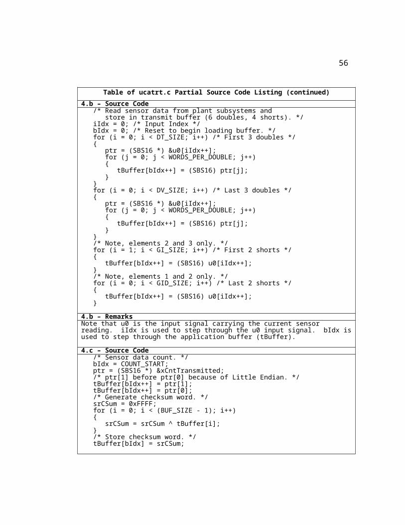
4.b – Source Code /* Read sensor data from plant subsystems and store in transmit buffer (6 doubles, 4 shorts). */ iIdx = 0; /* Input Index */ bIdx = 0; /* Reset to begin loading buffer. */ for (i = 0; i < DT_SIZE; i++) /* First 3 doubles */ { ptr = (SBS16 *) &u0[iIdx++]; for (j = 0; j < WORDS_PER_DOUBLE; j++) { tBuffer[bIdx++] = (SBS16) ptr[j]; } } for (i = 0; i < DV_SIZE; i++) /* Last 3 doubles */ { ptr = (SBS16 *) &u0[iIdx++]; for (j = 0; j < WORDS_PER_DOUBLE; j++) { tBuffer[bIdx++] = (SBS16) ptr[j]; } } /* Note, elements 2 and 3 only. */ for (i = 1; i < GI_SIZE; i++) /* First 2 shorts */ { tBuffer[bIdx++] = (SBS16) u0[iIdx++]; } /* Note, elements 1 and 2 only. */ for (i = 0; i < GID_SIZE; i++) /* Last 2 shorts */ { tBuffer[bIdx++] = (SBS16) u0[iIdx++]; }
4.b – RemarksNote that u0 is the input signal carrying the current sensor reading. iIdx is used to step through the u0 input signal. bIdx is used to step through the application buffer (tBuffer).
4.c – Source Code /* Sensor data count. */ bIdx = COUNT_START; ptr = (SBS16 *) &xCntTransmitted; /* ptr[1] before ptr[0] because of Little Endian. */ tBuffer[bIdx++] = ptr[1]; tBuffer[bIdx++] = ptr[0]; /* Generate checksum word. */ srCSum = 0xFFFF; for (i = 0; i < (BUF_SIZE - 1); i++) { srCSum = srCSum ^ tBuffer[i]; } /* Store checksum word. */ tBuffer[bIdx] = srCSum;
51
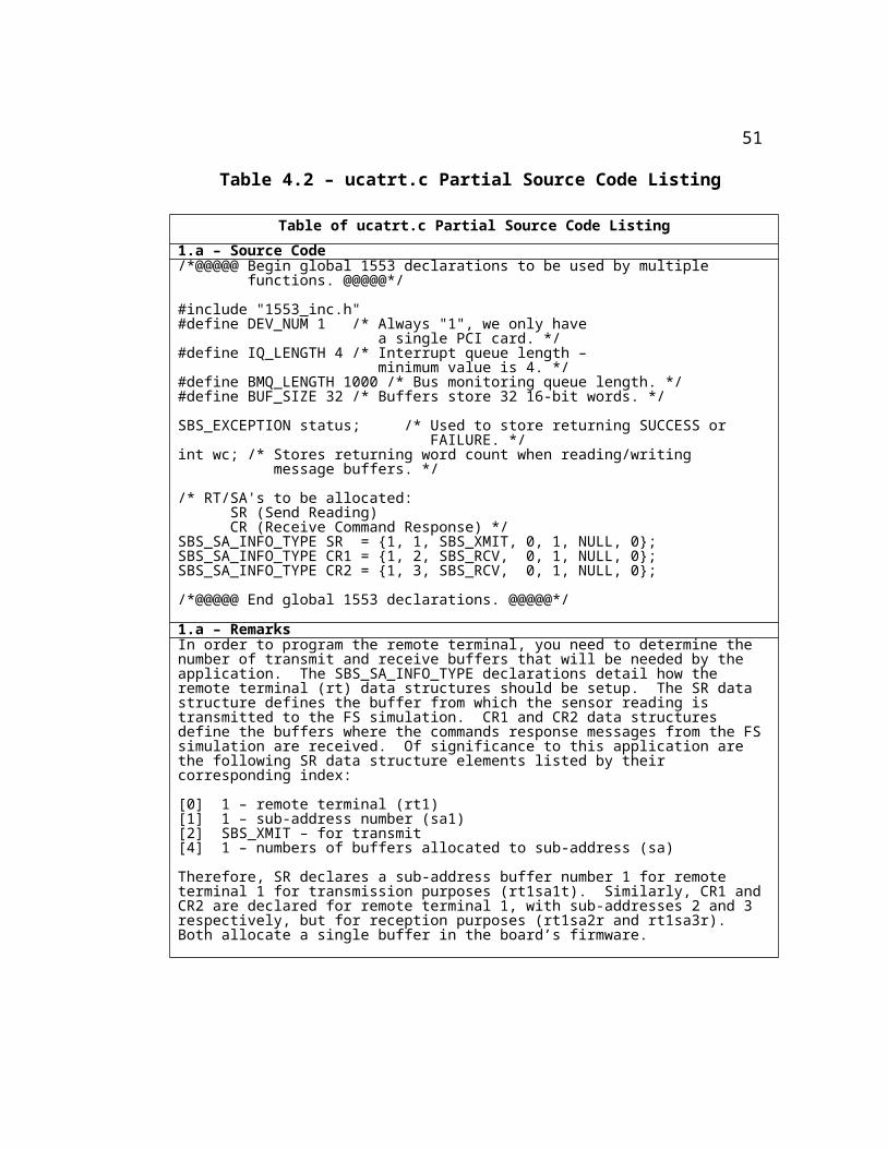
Table of ucatrt.c Partial Source Code Listing (continued)
4.c – RemarksOnce the sensor reading has been stored in the application buffer (tBuffer), move the buffer pointer to store the reading count and checksum words.
4.d – Source Code /* Write sensor data to SR firmware transmit buffer. */ wc = -1; wc = m1553_write_sa_buffer(DEV_NUM, BUF_SIZE, SR.buff_id[0], tBuffer); if (wc == 0) { ssPrintf("Failed to write to rt1sa1t buffer! Stopping sim...\n"); ssSetStopRequested(S, true); return; }
4.d – RemarksWrite the contents of the application transmit buffer (tBuffer) to the single firmware buffer (SR.buff_id[0]) allocated for this remote terminal sub-address.
4.e – Source Code /* Clear the busy bit on RT1's status word to signal to the BC that a new reading is available on rt1sa1t. */ stsWord.ushort = 0; stsWord.bits.rt_address = 1; /* RT1 */ stsWord.bits.busy = 0; status = SUCCESS; status *= m1553_load_status_word(DEV_NUM, 1, stsWord); if (status == FAILURE) { ssPrintf("Failed clearing RT1 status word busy bit.\n"); ssSetStopRequested(S, true); return; }
52

Table of ucatrt.c Partial Source Code Listing (continued)
4.f – Source Code /* Wait until the corresponding response from FS is received. This will be true when the response counts received are equal to the previous xCntTransmitted and when the checksum fields of the command responses received are the same as those calculated. */ stopSim = 0; r1XCntRcvd = -1; r2XCntRcvd = -1; cr1CSum = 0xFFFF; cr2CSum = 0xFFFF; cr1CSumRcvd = 0x0000; cr2CSumRcvd = 0x0000; while (!((r1XCntRcvd == xCntTransmitted) && (r2XCntRcvd == xCntTransmitted) && (cr1CSumRcvd == cr1CSum) && (cr2CSumRcvd == cr2CSum))) { if (stopSim == WAIT_CNT) { ssPrintf("Failed to receive response %d from FS! Stopping sim...\n", xCntTransmitted); ssSetStopRequested(S, true); return; } else { if ((xCntTransmitted == 0) && (cnt0 == 0)) { ssPrintf("Waiting for initial response from UCATFS sim...\n"); ssPrintf("Press UCATFS \"Start Simulation\" button to begin...\n"); cnt0++; } else if ((xCntTransmitted == 1) && (cnt1 == 0)) { ssPrintf("1553 UCAT simulation in progress...\n"); cnt1++; } }
53

Table of ucatrt.c Partial Source Code Listing (continued)
/* Read command response buffer 1. */ if (m1553_read_sa_buffer(DEV_NUM, CR1.buff_id[0], r1Buffer) > 0) { /* Store checksum received in buffer. */ cr1CSumRcvd = r1Buffer[CSUM_IDX];
/* Generate checksum from buffer just received. Note "(BUF_SIZE - 1)" is used because checksum field itself is not included in the calculation. */ cr1CSum = 0xFFFF; for (i = 0; i < (BUF_SIZE - 1); i++) { cr1CSum = cr1CSum ^ r1Buffer[i]; }
/* Read the count received rt1sa2r. ptr[1] before ptr[0] because of Little Endian. */ ptr = (SBS16 *) &r1XCntRcvd; ptr[1] = (SBS16) r1Buffer[COUNT_START]; ptr[0] = (SBS16) r1Buffer[COUNT_END]; }
/* Read command response buffer 2. */ if (m1553_read_sa_buffer(DEV_NUM, CR2.buff_id[0], r2Buffer) > 0) { /* Store CRC received in buffer. */ cr2CSumRcvd = r2Buffer[CSUM_IDX];
/* Generate checksum from buffer just received. Note "(BUF_SIZE - 1)" is used because checksum field itself is not included in the calculation. */ cr2CSum = 0xFFFF; for (i = 0; i < (BUF_SIZE - 1); i++) { cr2CSum = cr2CSum ^ r2Buffer[i]; }
/* Read the count received on rt1sa3r. ptr[1] before ptr[0] because of Little Endian. */ ptr = (SBS16 *) &r2XCntRcvd; ptr[1] = (SBS16) r2Buffer[COUNT_START]; ptr[0] = (SBS16) r2Buffer[COUNT_END]; }
stopSim++; }
54

Table of ucatrt.c Partial Source Code Listing (continued)
4.f – RemarksOnce the stopSim variable reaches the WAIT_CNT number, the Plant simulation will be stopped.
If it is the first time through the while loop (xCntTransmitted and cnt0 = 0), instruct the operator to startup the FS simulation. If the first sensor reading has already been processed (xCntTransmitted = 1 and cnt1 = 0), display a message informing the operator that the simulation has successfully started.
Within the while loop I read the two commands response receive buffers (rt1sa2r and rt1sa3r) waiting for the proper count. Once the command response messages with the count equal to the sensor reading count are received and if the checksum words received do not indicate a transmission error, exit the while loop.
4.g – Source Code /* Once we get here, the response from FS has been received. Stop FS from reading rt1sa1t by setting the RT’s busy bit. */ stsWord.ushort = 0; stsWord.bits.rt_address = 1; /* RT1 */ stsWord.bits.busy = 1; status = SUCCESS; status *= m1553_load_status_word(DEV_NUM, 1, stsWord); if (status == FAILURE) { ssPrintf("Failed while loading RT1 status word to set busy bit.\n"); ssSetStopRequested(S, true); return; }
4.h – Source Code /* Output command response data values. */ oIdx = 0; for (bIdx = 0; bIdx <= CMD_DATA_END; bIdx++) { y0[oIdx++] = r1Buffer[bIdx]; } for (bIdx = 0; bIdx <= CMD_DATA_END; bIdx++) { y0[oIdx++] = r2Buffer[bIdx]; }
4.h – RemarksoIdx index variable is used to set the value of the elements composing the output signal (y0). These values are extracted from the application buffers (r1Buffer and r2Buffer) that were in turn populated from the response commands data last received on the firmware buffers (rt1sa2r and rt1sa3r).
55

Table of ucatrt.c Partial Source Code Listing (continued)
4.i – Source Code /* Increment xCntTransmitted to be used on next sim step. */ xCntTransmitted++;
ucatrt_Outputs_wrapper(u0,u1,y0);}
4.i – RemarksxCntTransmitted is incremented to represent the next sensor reading count to be processed by the next execution time step.
5.a – Source Code/** * Function: mdlTerminate * Abstract: * Stop bus IO and close the 1553 ABI-PCI-1 device. */static void mdlTerminate(SimStruct *S){ sbs_stop_io(DEV_NUM);5.b – Source Code sbs_close_device(DEV_NUM); return;}
5.a,b – RemarksThe mdlTerminate callback function is forcibly called whenever and however the simulation ends to make sure that the 1553 board is not left open (even if errors were encountered during the simulation execution). Adding the SS_OPTION_CALL_TERMINATE_ON_EXIT option to the Simulink ssSetOptions function call in the mdlInitializeSizes callback causes the latter to happen. For clarity purposes, the listing of mdlInitializeSizes has not been included in this section. The full listing of the ucatrt.c S-function is provided in Appendix B of this document.
56
Now that I’ve disclosed the S-functions’ source code, I will discuss how they get compiled and thus incorporated into the execution cycle of the simulation. Since both S-functions make calls to the SBS Integrated Avionics Library to interface and interact with the 1553 hardware boards, they are compiled along with the SBS library support files. Table 4.3 – Source Files to Compile to Generate DLLs lists the source files that when compiled and linked generate the required Microsoft Windows DLLs. Note that the first line lists ucatbc.c and ucatrt.c, the two S-functions described in this section. ucatbc_wrapper.c and ucatrt_wrapper.c on the following line are automatically created when the ucatbc.c and ucatrt.c skeleton files are generated by the S-function Builder Wizard [9]. They are not used in this application and thus remain skeletons with two function declarations but with empty bodies and thus no executable instructions. These wrapper files are recommended when used in conjunction with the The Mathworks, Inc.’s Real Time Workshop product, which this solution does not use. Nevertheless, they must be included in order for the compilation to succeed. Note that llwin32.c, parser.c, dev_mgmt.c, 1553_dm.c and all the include (*.h) files are commonly needed by both DLLs. 1553_bcm.c and 1553_rtm.c contain functions specific to the operation of the bus controller and remote terminals respectively. Since these support files are supplied by SBS as part of their Integrated Avionics Library, they include a copyright notice similar to the one shown below in Figure 4.3.
57

/*====================================================================== * Copyright (c) 2001 by SBS Technologies, Inc. * 2400 Louisiana Blvd., NE * AFC Building 5, Suite 600 * Albuquerque, New Mexico 87110 * Technical support (toll free) * 877-TECHSBS (877-832-4727) *====================================================================== * SBS INTEGRATED AVIONICS LIBRARY Version 7.16 * Last Modified 16 Apr 03 *====================================================================== * This software is Licensed to be used only in connection with a SBS * adapter. If this Software is merged with any other software program * it is subject to the terms and conditions of this license. If you * copy this software, you must reproduce and include all copyright * notices and any other proprietary rights notices. * For full information on the License Agreement please see the included * License.txt file. *======================================================================
Figure 4.3 – SBS Copyright Notice
Table 4.3 – Source Files to Compile to Generate DLLs
Table of Source Files to Compile to Generate DLLsTo generate ucatbc.dll To generate ucatrt.dll
ucatbc.c ucatrt.cucatbc_wrapper.c ucatrt_wrapper.c
llwin32.c llwin32.cparser.c parser.cdev_mgmt.c dev_mgmt.c1553_bcm.c 1553_rtm.c1553_dm.c 1553_dm.c1553_inc.h 1553_inc.hddsbs.h ddsbs.h
dev_mgmt.h dev_mgmt.hsbs_sys.h sbs_sys.hsbshlp.h sbshlp.hsbspci.h sbspci.h
58

In order to compile these files into the required DLLs, I used the MEX command at the Matlab Command Window command line. MEX stands for “Matlab EXecutable” and the resulting file extension varies from platform to platform [9]. In this case, the executable extension is "dll" as required by the Microsoft Windows 2000 operating system. The full MEX command line used to generate ucatbc.dll is shown below:
mex ucatbc.c ucatbc_wrapper.c ll_win32.c parser.c dev_mgmt.c 1553_dm.c 1553_bcm.c
Note that the above line is typed as a single line on the "Matlab Command Window" prompt. Note also that the local disk directory where these files are located must contain the listed include (*.h) files. The same is true of the MEX command line below that generates the ucatrt.dll file:
mex ucatrt.c ucatrt_wrapper.c ll_win32.c parser.c dev_mgmt.c 1553_dm.c 1553_rtm.c
Additionally, though not clearly seen above, the MEX command incorporates the use of the “Mathworks' LCC” compiler included with Matlab to compile and link the C source files and to then build the DLL file that the S-function blocks call during the simulation progression [6]. By default, MEX uses the bundled LCC compiler, but it allows for the integration of other third party compilers. To configure the MEX command to use a third party compiler (i.e. Microsoft Visual C) instead of the default Mathworks' LCC compiler, I used the mex –setup Matlab
59

command [9]. The latter implies that the Microsoft Visual C compiler must be installed prior to calling the mex –setup command. I initially selected the Microsoft Visual C compiler instead of the Mathworks LCC compiler because it is the compiler in use by the SBS technical support staff to develop 1553 applications based on their Integrated Avionics Library. Unfortunately, as I describe later in Section 7 - Submounted Obstacles, the results obtained when using the Microsoft Visual C compiler were not the same as those obtained when using the Mathworks LCC compiler. The mission analysts use the Mathworks LCC compiler in their simulations.
To conclude, in this section I described in detail the primary callback functions that make up the Simulink S-functions or interfaces to the 1553 bus: mdlInitializeConditions, mdlOutputs, and mdlTerminate. I described how Simulink calls these callback functions at critical points during simulation execution. I outlined the steps taken by the 1553 interface blocks to facilitate the exchange of sensor reading and corresponding commands response required every 20 milliseconds of plant simulation time. I referred the reader to the 1553 S-function Interface Full System Flowchart in Appendix E for a visual representation of the interface tasks performed by the S-functions. I listed the source code required to perform each task along with any clarifying remarks I thought were necessary. Finally, I showed how to compile and link the S-function source code into the necessary DLLs. These DLLs are called by the Simulink S-functions whenever communication via the 1553 bus is required.
60

61

Section 5 – Integrated Simulation Run
Once the 1553 interface S-functions are compiled and linked, the 1553 S-function blocks (ucatbc and ucatrt) will call their respective callback functions at the specified points during simulation execution. At every 20 ms of Plant simulation time, the mdlOutputs callback function is called to retrieve the new sensor reading. The FS simulation will detect the new sensor reading, process it and return the corresponding commands response. This processing of sensor readings will continue until the integrated simulation is completed. Before any of that can take place though, a process to begin the execution of the simulations must be followed. This section describes this process by expanding on the required steps listed below:
1. Power on both UCATFS and UCATPLANT computer systems.
2. Startup the Matlab application on both systems3. Load the two Simulink simulations (FS and Plant)4. Startup the Plant simulation and wait for message on the
Plant's Matlab Command Window to start the FS simulation
5. Startup the FS simulation6. Wait for integrated simulation to complete
62

Note that the above process assumes that Matlab and Simulink products have been successfully installed on both UCATFS and UCATPLANT computer systems.
63

After the computers have started (step 1), login with the required user account and double-click on the Matlab icon or shortcut to startup the Matlab application (step 2). To load the FS simulation on the UCATFS computer, enter the following commands on its Matlab Command Window:
>> cd c:\ucat_fs>> load ucat_init_exec.mat>> ucat_fs
To load the Plant simulation on the UCATPLANT computer, enter the following commands on its Matlab Command Window (step 3):
>> cd c:\ucat_plant>> load ucat_init_exec.mat>> ucat_plant
Note that the c:\ucat_fs and c:\ucat_plant directories on their respective computers house the Simulink model files (ucat_fs.mdl and ucat_plant.mdl) where the simulations are defined/stored. These directories also contain the C source code and header files required by the S-function blocks. Used by both simulations is the ucat_init_exec.mat file. This file initializes the Matlab workspace variables. The initialization value of these variables was determined by the mission analysts and cannot be explored further here because of their proprietary nature. The ucat_fs and ucat_plant commands start up Simulink with the appropriate simulation model loaded ready to begin execution.
64

To begin the execution of the integrated simulation, click on the Simulink “Start simulation” button on the Plant simulation (UCATPLANT computer) (Step 4). The Plant simulation must be started first because it has the 1553 remote terminal, which must be ready with the first sensor reading before the bus controller (FS simulation) can read it. After the Plant simulation begins, it loads its transmit buffer with the first sensor reading and signals the operator to start the FS simulation with the message:
Waiting for initial response from UCATFS sim…Press UCATFS “Start Simulation” button to begin…
When the operator sees the above message on the UCATPLANT’s computer Matlab Command Window screen, he/she must click on the “Start simulation” button on the FS simulation (UCATFS computer). The latter will begin the execution of the 1553 bus controller (Step 5). The bus controller will begin reading the Plant’s transmit buffer until the first reading is detected. The first reading will be detected when the expected count received is zero and when the received and calculated checksum values for the message match up. Once the FS simulation detects the first reading, it processes it (by triggering the FS block) and returns the corresponding commands response to the Plant’s receive buffers. Once the Plant, which has been waiting, receives the response to the first sensor reading, it forwards the new commands to the RELAYS & SWITCHES block and proceeds to read and load the following sensor reading at the next 20 ms simulation time step. This process continues until all 2200
65

message exchanges have been executed and the simulation finishes.
66

Once the integrated simulation has completed, its results must be gathered. The rest of this section describes the steps required to get this done:
a. Save results of FS simulation to compare directoryb. Save results of Plant simulation to compare directoryc. Combine FS and Plant simulation results into single
results file
The steps above make reference to a “compare directory”. This is a directory I arbitrarily called “C:\SimComp” and created on the UCATPLANT computer. To save the results of the FS simulation to the “C:\SimComp” directory on the UCATPLANT computer, I used a network file share assigned to drive “E:” on the UCATFS computer. Once drive “E:” is connected to the “C:\SimComp” directory on UCATPLANT, the results of the FS simulation can be saved there directly from the UCATFS Matlab Command Window as follows:
>> cd E:\SimComp>> save 1553_fs_subset.mat VAR1 VAR2 VAR3 VAR4 VAR5 mdlClock
Note that VAR1 through VAR5 are flight software arrays of signal values of significance to the mission analysts that get stored in the UCATFS Matlab workspace whenever the FS block is triggered to execute. The mdlClock variable array tracks and stores the Plant’s simulation time as it progresses once every 20 milliseconds. The save command stores the contents of the five
67

variables (VAR1 through VAR5) and mdlClock to the file 1553_fs_subset.mat. The file is stored on the C:\SimComp directory of the UCATPLANT computer via the network file share connection. I setup this file share connection to be established automatically from UCATFS to UCATPLANT immediately after user login. The latter implies that the UCATPLANT computer needs to be in operation before the operator logs into the UCATFS computer. At this point, "step a" above has been completed.
"Step b" can be completed from the UCATPLANT computer’s Matlab Command Window after the Plant simulation has finished executing as follows:
>> cd C:\SimComp>> save 1553_plant.mat
Finally, the two result files (1553_fs_subset.mat and 1553_plant.mat) can be combined using the following commands on UCATPLANT's Matlab Command Window:
>> clear all>> load 1553_fs_subset.mat>> VAR1.time=mdlClock.signals.values>> VAR2.time=mdlClock.signals.values>> VAR3.time=mdlClock.signals.values>> VAR4.time=mdlClock.signals.values>> VAR5.time=mdlClock.signals.values>> clear mdlClock>> save 1553_plant.mat -APPEND
68

Note that the above commands can be added to a Matlab script to automate their execution. I chose to call such a script addfs2plant.m. Once the above commands are done executing, the 1553_plant.mat file has the results of the integrated simulation. Once the integrated results are saved, they can be compared with the results obtained by the execution of the original simulation on one of the mission analysts' computers.
In this section I’ve described how to execute the integrated 1553 simulation by synchronizing the startup of both FS and Plant simulations. In addition, I discuss how to combine the results of both FS and Plant simulations into a single Matlab (*.mat) file that can be compared to a file generated by the original simulation.
69

Section 6 – Results Comparison
In the introduction to this document I stated that the intent of this study was to partition an original simulation model executing on a single physical computer into two simulation models each executing on a separate computer but connected via a 1553 avionics bus. I called the latter the “integrated” simulation because of the 1553 bus integration it contained. The question of how to assess the success or failure of this study has not yet been addressed. That is the intent of this section. This section will compare the results obtained by the original simulation with those obtained by the integrated simulation. This comparison will show that the integrated simulation results are identical to those obtained by the original simulation. It will also show that even though there is some performance degradation introduced by the 1553 bus integration, that the degradation is acceptable given the new capabilities the integrated version of the simulation provides.
In Section 5 – Integrated Simulation Run I showed how to combine the results of the FS and Plant simulations into a single (integrated) results file that I called 1553_plant.mat. I obtained the results of the original simulation run from one of the mission analysts who ran it on his desktop computer. I renamed the original results file from its initial name to Orig.mat. I copied
70

these two files to the “compare directory” which I called SimComp and which resides on the root of UCATPLANT’s C: drive (C:\SimComp). I then modified an existing Matlab script initially developed by one of the mission analysts to plot the results of both simulations for three carefully selected analysis characteristics: Rocket Altitude, Angular
71

Rate in the Body Frame and Guidance Commands. A listing of the resulting Matlab script is not provided here due to the proprietary nature of the variable names used within. By comparing the plot results, you will clearly see that they are identical. Therefore, the integration of the 1553 bus as described in this document does not introduce errors into the simulation.
The pages that follow will display four plots per analysis characteristic (i.e.: two plots per page or two pages per characteristic). For each characteristic, the first two plots will be those generated by the results of the original and integrated 1553 simulations. The third and fourth plots will be those generated after merging the first two plots and after calculating their differences respectively. Both the merged and differences images will show that the original and integrated results are identical. It must be noted that even a single bit error in one of the 1553 messages traversing the bus while the simulation ran would have resulted in very visible differences in the merged and differences plot images. Any such difference(s) would signal an unacceptable error in the integrated simulation.
The first set of four plots (Figures 6.1, 6.2, 6.3 and 6.4) that follow compare the altitude in feet of the rocket from the time of launch to the time when the spacecraft separates from the vehicle at 2200 seconds. The next set of four plots (Figures 6.5, 6.6, 6.7 and 6.8) compare the roll, pitch and yaw angular rates in the body frame in degrees per second through the same time period. Finally, the last four plots (Figures 6.9, 6.10, 6.11 and 6.12) compare the guidance commands to pitch and yaw in degrees per second over the same time period.
72

Figure 6.1 – Rocket Altitude Generated by Original Simulation
73

Figure 6.2 – Rocket Altitude Generated by Integrated 1553 Simulation
74

Figure 6.3 - Merged Rocket Altitude Plots
Figure 6.4 - Differences in Rocket Altitude
75

Figure 6.5 – Angular Rate in the Body Frame Generated by Original Simulation
Figure 6.6 – Angular Rate in the Body Frame Generated by Integrated 1553 Simulation
76

Figure 6.7 - Merged Angular Rate in the Body Frame Plots
Figure 6.8 - Differences in Angular Rate in the Body Frame
77

Figure 6.9 – Guidance Commands Generated by Original Simulation
Figure 6.10 – Guidance Commands Generated by Integrated 1553 Simulation
78

Figure 6.11 - Merged Guidance Commands Plots
Figure 6.12 - Differences in Guidance Commands
79

The plots on Figures 6.1 thru 6.12 showed that the results obtained by the original simulation are identical to those obtained by the new simulation with the integrated 1553 avionics bus. In addition, they show that the integrated simulation is capable of executing without a single 1553 transmission error since a single bit error on any message would have registered as a difference on the merged and/or differences plots. But now that the integrated version of the simulation has been shown to be accurate, how does it perform in terms of execution elapsed time when compared to the original simulation run?
Table 6.1 – Elapsed Time Performance Comparison that follows shows the measured elapsed time of twenty individual runs. Ten are of the original simulation and the other ten are of the integrated 1553 simulation. They are sorted from least time to most time starting at the top of the table. The table also shows the differences between the original and the integrated runs on the right hand column and finally, the averages of the values in the last row. Note that the average difference is 734.6 seconds or around 8.4 percent performance degradation when using the average original value of 8,768.5 seconds as the basis for the percentage calculation. Note that 8.4 percent performance degradation is acceptable to the mission analysts considering the benefits gained by having access to an actual 1553 bus and being able to incorporate physical rocket devices into their simulations.
At this point I cannot explain with any certainty why the elapsed times for the simulation runs (original or integrated 1553) vary. This is true eventhough they were executed on the same hardware and under the same conditions. UCATFS and
80
UCATPLANT were cleanly restarted before executing each run and had the same visible processes running. I can only speculate that there were unseen kernel, operating system or Simulink processes making different decisions at the same times during simulation execution.
Table 6.1 – Elapsed Time Performance Comparison
Table of Elapsed Time Performance Comparison
Original (sec) Integrated (sec) Difference (sec)
8,709.3 9,392.7 683.4
8,728.3 9,398.6 670.3
8,737.6 9,468.4 730.8
8,752.3 9,480.6 728.3
8,764.4 9,499.8 735.4
8,779.8 9,513.1 733.3
8,791.4 9,516.1 724.7
8,800.8 9,551.6 750.8
8,801.7 9,584.3 782.6
8,819.2 9,626.1 806.9
8,768.5 9,503.1 734.6
In conclusion, I have shown that the integrated 1553 simulation results are identical to those obtained by the original simulation. I did this by displaying plot results generated by the original and integrated runs on the same page. Even though the similarities should be obvious by comparing the results of those two runs, I also merged the two into a third plot and plotted their differences on a fourth one. The merged and differences plots unequivocally show that the results achieved by the integrated runs are identical to the original runs. Finally, I rated the success of the study by comparing the original versus the
81

integrated overall simulation elapsed times. This comparison resulted in an acceptable 8.4 percent performance degradation. Unfortunately, it will take further investigation to determine why there are variations in the simulations' elapsed times. Ultimately, the final word on whether the study was a success or a failure rests on the shoulders of the mission analysts (the definitive customers) and they have repeatedly expressed their satisfaction with the solution as implemented.
82

Section 7 – Surmounted Obstacles
On course to completing this task there were some significant obstacles that I had to overcome. I feel that reporting about them here would give the reader an advantage if and when he or she was ever faced with a similar situation. The following text will discuss why I decided to use the S-function approach to solve the problem. It will talk about the fortunate circumstances that facilitated the availability of all the hardware and software tools needed to develop the prototype. It will describe the efforts I embarked upon to solve 1553 message racing conditions that resulted in the transmission and reception of corrupt 1553 messages to and from both FS and Plant simulations. It will also raise awareness of a finding that shows that executing the original simulation in Simulink “Normal” versus “Accelerated” mode generates different results. These results are different even if the normal and accelerated runs execute on the same computer.
In order to bestow a Simulink simulation with the capability to command the 1553 interface cards to transmit and receive the required messages I spoke to The Mathworks, Inc. training and technical support representatives as well as third party vendors knowledgeable in this area. I spoke to technical representatives from Condor Engineering (http://www.condorengineering.com) and from SBS Technologies, Inc. (http://www.sbs.com). Whilst
83

discussing the possibilities, two options surfaced as likely candidates: C-MEX S-functions called by simulation blocks or Real-Time Workshop if real-time capabilities were required. After discussing these two options with the mission analysts, it became apparent
84

that being able to run the simulations in real-time was not a requirement. In fact, being able to execute the simulation faster than real-time was desirable. The faster the simulation ran, the better, since it would allow for the analysis of multiple runs in the same amount of time it would take a real-time run to execute. That left the S-function approach as the preferred mechanism to try and solve the problem.
Unfortunately, the desire to run faster than real-time was not achieved by this solution. This was expected since adding 1553 hardware and software to the same computer that ran the original simulation slower than real-time would only increase the simulation’s complexity and accordingly its execution time. Fortunately, as Section 6 – Results Comparison showed, the performance degradation was only about 8.4 percent when compared to the original simulation. In order to achieve better performance, hardware with faster processor clock cycles will be required. This should not be hard to do given the capabilities of today’s systems. The clock speeds of the processors I used were 450 MHz for UCATFS and 550 MHz for UCATPLANT respectively (See Appendix A – Hardware and Software Prototype Description). Systems can be procured today at clock speeds well in excess of 3000 MHz (see DELL, Hewlett Packard, Compaq or similar manufacturer websites for confirmation). The 1553 bus utilization also showed room for growth on the 1553 bus analyzer by never exceeding 56 percent during the integrated simulation runs.
Another hurdle that I had to overcome was that of obtaining the hardware and software needed to implement the prototype.
85

In this endeavor I was quite fortunate. Being a NASA employee and personally knowing people that worked in support of the International Space Station (ISS) came in very handy. Like many launch vehicles, ISS also uses the 1553 standard to communicate between devices [7]. This could have been one of the most difficult tasks since the cost of the 1553 interface cards I used is around $10,000.00 each and they would have had to be procured. After two phone calls and a short car trip I was able to borrow for an indefinite amount of time two of the SBS 1553 ABI-PCI-1 cards I needed for the UCATFS and UCATPLANT computers. In addition, on that same trip, I came across all of the 1553 cabling and stubs I needed to setup the bus. But, to properly complete the bus, I needed to find the 1553 78 ohm terminators. A few days later after two more phone calls and two more car trips, I obtained the terminators from people who also worked for NASA in support of the ISS. The last piece of bus hardware I wanted was a 1553 bus analyzer that would allow me to monitor the 1553 message traffic. Though a bit more difficult to find and a bit more costly (around $12,000.00), that came as a loan from my ISS acquaintances. The analyzer uses a PCMCIA card to interface to the bus and a standard laptop with a PCMCIA port running the Microsoft Windows ‘98 operating system. The analyzer product is sold by SBS under the name of PASS-3200 and it includes the software needed to capture the 1553 messages (see the SBS website for more information at http://www.sbs.com). Figure 7.1 – Final 1553 Bus Configuration below shows the final bus configuration I used.
86

Figure 7.1 – Final 1553 Bus ConfigurationOnce I had the bus setup, I needed to settle on the systems to
use for UCATFS and UCATPLANT. Since the mission analysts used Intel-based systems running Microsoft Windows 2000 as their operating system and since I needed PCI buses to connect the 1553 cards, that question was settled. In our computer laboratory I found two Intel-based desktop computers no longer in active use with PCI ports. The next step was to upgrade their memory since 256 MB on one and 512 MB on the other would not have been enough based on information obtained from the mission analysts. I made a few more phone calls to other individuals within the organization and found the memory modules to bring one of the computers to 768 MB of system memory and the other to 1000 MB (1 GB) of system memory. This completes the description of the products I used to implement the hardware solution. See Appendix A for a more detailed specification.
Now that I had the hardware, the next task was to obtain the required media and software licenses to install on UCATFS and
87

UCATPLANT computers. The mission analysts owned the Microsoft Windows 2000 and Matlab/Simulink licenses I needed to use. As mentioned previously, the Matlab/Simulink suite is one of the analysis tools of choice of the mission analysts. The Microsoft Visual C I obtained from another group within NASA who was no longer using their licensed copy. The installation of these products went smoothly following the instructions supplied by the manufacturer. Installing the PASS-3200 software on the laptop computer required calling SBS technical support and proving that I indeed had the PASS-3200 product before getting a password to their Internet download website. Once I had the password, I downloaded the new version of the PASS-3200 software and installed it on the laptop. Using that same website I downloaded their latest Integrated Avionics Library source code and firmware update file for the 1553 PCI boards (ABI-PCI-1) and installed them in UCATFS and UCATPLANT computers. I then spoke to a representative of SBS Technical support staff to assist me in the creation of the required sbs_dev.cfg configuration file. See Appendix C – sbs_dev.cfg Listing for a complete listing of the configuration file contents. In general, the configuration file identifies the hardware device installed on the computer along with its name and the corresponding firmware filename. The Integrated Avionics Library source code came with relatively simple sample applications that I learned to individually compile and run using the Microsoft Visual C compiler. These applications presented a very good starting point for the development of the S-functions (ucatbc.c and ucatrt.c) and for learning about the development of basic 1553 applications. A
88

more thorough understanding of the code came after exchanging multiple electronic mail messages and telephone discussions with SBS’ technical support staff. Finally, installation of the original simulation files along with their initialization scripts came with the help of one of the mission analysts. The latter involved copying files from a compact disc containing the original UCAT simulation files to UCATPLANT’s hard disk drive. This completes the description of the software products I used to implement the solution. See Appendix A for a more detailed specification.
Undoubtedly the most difficult obstacle I had to overcome was the racing condition that occurred when the bus controller program was instructed to run in a loop. Because all of the examples I received from SBS’ technical support used a looping program for the bus controller, I mistakenly assumed that to be the normal mode of operation. The problem which I failed to realize was that in such a mode, the bus controller was constantly reading UCATPLANT’s transmit buffer to get the next sensor reading and sending the commands response from the FS block to UCATPLANT’s receive buffers regardless of what their contents were. In this mode, the bus utilization remained constantly at 99 percent. The transmission of this large number of messages was too much for the firmware on the boards and for the application software (the S-functions themselves) to keep up with. The consequence of keeping the bus so busy was the transmission and reception of corrupted 1553 messages that would indubitably skew the simulation results. SBS’ technical support staff confirmed that the bus utilization should be
89

normally around 60 to 65 percent and that it was very likely that a racing condition was taking place at 99 percent.
I then began to compare the data that was being sent and received by the S-functions against the data in the actual 1553 messages being captured by the bus analyzer. I noticed that what the S-functions were sending and receiving did not match with the messages being transmitted on the bus. The messages were only partially correct. That is, part of the message had data belonging to the new reading while the other part had data from the prior reading. A similar behavior could be seen when the commands response messages were being transmitted. Once I understood that this racing condition or corruption of data was taking place, I still did not realize that the problem was the looping of the bc program. Instead I thought that the bus controller was just running too fast and therefore I began looking at ways to slow it down. With help from one of my ISS acquaintances, I began by increasing the inter-message gap from the default of 10 microseconds to 40, then to 80, 160, 320, 640 and finally to 1280 [5]. At an inter-message gap of 1280 microseconds, the integrated simulation finally ran without errors! Unfortunately, its elapsed time increased considerably from less than two to about six hours! In addition, even after slowing down the bus controller commands in such a fashion, 1553 messages with corrupted data were not consistently and completely eliminated. Some simulation runs would continue to show significant differences in the plot comparisons while others matched up exactly. The latter was definitely a move in the right direction since some of the results were often accurate and as
90

such would converge with the plots of the original simulation. Unfortunately, other runs would continue to generate results that showed significant plot differences. These differences would often not be visible until I enlarged (zoomed into) sections of the plots multiple times. This too was a welcomed occurrence since it meant that the rocket was actually launching successfully and delivering its cargo to the proper orbit. In addition, I noticed that the bus utilization decreased as I increased the inter-message gap. The latter further confirmed that I was on the right track and that previously the bus controller was flooding the bus with messages without giving the S-functions or the cards’ firmware enough time to react to them. After pondering on what could be causing this problem, I resolved to examine the 1553 transmissions more closely.
I had to come up with a way of detecting if and when a 1553 transmission error occurred. I chose to add debugging code to both S-functions. The debugging code would simply create a file at the beginning of the simulation, write to it at every execution time step the data that the S-function block received and transmitted, and close the file at the end of the simulation. By doing this on both S-functions (ucatbc.c and ucatrt.c), I created two text files with every sensor reading and corresponding command response exchange. The FS simulation created one text file while the Plant simulation created the other. I was then able to compare both files and detect any differences. Even a single-bit error difference on any of the transmitted or received data would be detected along with the corresponding simulation time when the error actually occurred.
91

After additional discussion with SBS technical support staff, I was instructed to insert BC_DELAY instructions between bc program commands. After implementing the recommended changes, I began to notice that this approach served a similar purpose as increasing the inter-message gap between bc commands I had previously tried. That is, it would slow down the flow of messages on the bus, increase the accuracy of the run and reduce the bus utilization. Unfortunately, as before, it did not completely solve the problem. I began by inserting 250 microsecond delays, then 500, 750, 1000 and finally 1250. At 1250, the runs took around six hours again to execute! In addition, the text file comparisons intermittently continued to show 1553 transmission errors occurring. The number of errors decreased as the delay increased, but even a single 1553 transmission error would result in plot comparisons that failed to converge or match.
At this point I began to wonder if the plot differences were in some way attributed to the hardware the simulation was running on. I asked one of the mission analysts how the original simulation and associated results were obtained. He told me that he had used Simulink’s “Accelerated” mode to run the original simulation on his desktop computer. All of my simulation runs up to this point had been using “Normal” mode. I proceeded by running the original simulation using accelerated mode on the UCATPLANT computer. What I found when I compared UCATPLANT’s accelerated run with the mission analyst’s accelerated run (the one I had been comparing against up to now) was that significant plot differences still existed. Therefore,
92

accelerated runs on different hardware platforms generated different results. I then ran the original simulation in normal mode on the UCATPLANT computer and compared its results against the results of the accelerated run on the same UCATPLANT computer. The resulting plot comparisons also showed significant differences (see Figure 7.2 - Accelerated vs. Normal GC Differences). This implied that the accelerated and normal runs of the original simulation on the same computer hardware and software generated different results! I confirmed this by asking the mission analyst to perform the same experiment on his desktop computer. He too noticed significant differences between the accelerated and normal mode runs on the same hardware of the original simulation. This was a significant finding since, up to now; the mission analysts were under the erroneous assumption that normal and accelerated runs were generating the exact same results.
93

Figure 7.2 - Accelerated vs. Normal GC Differences
Lastly, I asked him for the results generated by his normal run of the original simulation. I compared his normal run results to the results of one of my integrated 1553 runs. I made sure that the integrated 1553 run results had no 1553 transmission errors and, much to my surprise, I discovered that the comparison plots were identical throughout the entire 2200 second run! This was a significant milestone indeed since it confirmed not only that an exact match could be achieved between the original run and the integrated 1553 run, but also, that it made no difference on what hardware the normal original simulation run was executed.
94

At this point, I knew that I could sporadically achieve accurate integrated 1553 simulation runs, but that the runs took an unacceptably long time to execute and that some of them, even at this reduced execution rate, still showed 1553 transmission errors. I continued to ponder the problem for some time until I recalled a doubt I previously had when I initially began compiling and running the SBS sample applications I received with their Integrated Avionics Library. I had then wondered why it was that the bus controller program chains were always configured to loop. I remembered bringing this question to a member of the SBS technical support staff then, but did not recall getting a clear answer. I decided to devise a non-looping approach with two separate bc program chains instead of just one: one chain that would cause the ucatbc.c S-function to get the sensor reading from the Plant simulation, but only when the Plant was no longer busy, and another chain that would require the ucatbc.c S-function to send the corresponding commands response only after it was done processing the current sensor reading. I outlined my proposition in an electronic message to SBS technical support and was surprised to receive confirmation to proceed with my proposed non-looping approach.
I then needed to overcome two new challenges in order to implement the non-looping approach: first, I needed to be able to detect when a chain completed executing before starting it again and second, I needed to detect when the Plant simulation was no longer busy indicating that it was ready with the next sensor reading on its transmit buffer. I was able to overcome these two hurdles again with the help of SBS technical support and the
95

sample code included in their Integrated Avionics Library. To detect whether a chain is done executing, I used:
while (LL_get_ram(DEV_NUM, SBS_BCCPTR) != (SBS16) 0) {}
SBS_BCCPTR is a pointer to the bus controller program block that is currently executing. Since the blocks of a chain are executed in order of their number in a linked list of blocks, whenever the block number returns back to zero, it signals that the chain has completed executing. As long as the block number is not zero, the chain is still running and the bus controller must wait. To detect when the Plant was no longer busy, I used the remote terminal message status word’s busy-bit. Every transmitted remote terminal message comes coupled with a status word that the bus controller can read to detect errors in the transmission [1]. On the Plant side I used the following code to set its status words’ busy-bit:
stsWord.ushort = 0;stsWord.bits.rt_address = 1; /* RT1 */stsWord.bits.busy = 1;status = SUCCESS;status *= m1553_load_status_word(DEV_NUM, 1, stsWord);if (status == FAILURE){ ssPrintf("Failed while loading RT1 status word to set busy bit.\n"); return;}
The code above clears a status word, loads the word with the relevant remote terminal address (1 in this case), sets the busy-bit of the word and finally loads the status word to the card’s firmware returning a failure if the load command fails. This code
96

is similarly used to reset the busy-bit except that the stsWord.bits.busy line is set to zero instead of one. As long as the busy bit was set, the Plant signaled to the bus controller that the next sensor reading was not yet ready and that it was busy processing its current simulation step. Once the busy-bit was cleared, the bus controller knew that a new reading was awaiting processing and that it should accept the message data as the next complete and valid sensor reading.
Once I incorporated the last two changes discussed, I was able to consistently get the integrated 1553 simulation runs to generate results that were almost an exact match to the results obtained by the mission analyst's original simulation. I say "almost" because there was still one plot that showed a noticeable difference. This difference was small, in the range of 10-10 and 10-11 degrees per second, but it was still a difference I could not explain (see Figure 7.3 - VCC vs. LCC GC Differences). The guidance commands are the outputs of the FS
block. By examining the inputs to the FS block on both simulations, I confirmed that they were identical, yet the plot was showing that the corresponding outputs were slightly different. I also knew that the FS block had not been significantly modified, but that within it existed another S-function that I had previously compiled using the Microsoft Visual C compiler. I call this S-function the "internal" S-function because its actual name cannot be revealed due to proprietary concerns. Since the mission analyst that had given me the original simulation results had used LCC to compile this internal S-function, I thought it wise to compile all three S-functions (ucatbc, ucatrt and internal) in the
97

integrated 1553 simulation using LCC instead. The suspicion was that the calculations being made by the internal S-function were generating different results. This would be possible only if the compilers had made different decisions when building the internal S-function DLL.
Figure 7.3 - VCC vs. LCC GC Differences
Much to my delight, after successfully building the integrated simulation's S-functions using LCC, and after performing another integrated simulation run, there were no differences in the guidance commands plots (see Figure 6.12 - Differences in Guidance Commands). The latter building of S-functions was
98

by no means a simple matter. When I first attempted to compile the S-functions using LCC, I discovered that the compilation and linking process would fail with the following errors:
lcc preprocessor error: .\dev_mgmt.h:2006 .\1553_inc.h:33 dev_mgmt.c:146 Macro redefinition of SBS_SET_BIT
lcc preprocessor error: .\dev_mgmt.h:2008 .\1553_inc.h:33 dev_mgmt.c:146 Macro redefinition of CLEAR_BIT
Further investigation revealed that dev_mgmt.h was erroneously being included more than once in the SBS Integrated Avionics Library files. This was causing the LCC errors above which were obviously not being caught by the Microsoft Visual C compiler. This goes to show that compilers are not all the same and that everything depends on who develops them and how. It turns out that the two #define statements below were not within the proper #ifndef and #endif preprocessor directive section:
#define SBS_SET_BIT(word, bit)(word) | (1 << (bit))#define CLEAR_BIT(word, bit)((word) & (~(1 << (bit))))
After bringing this to the attention of SBS technical support staff, they have acknowledged that this is a problem with their integrated library and will incorporate the change in its next release.
In conclusion, after overcoming the obstacles just described, the integrated 1553 simulation will consistently generate results exactly equal to those generated by the original simulation. This is even true if the original simulation runs are executed on different mission analyst workstations (i.e.: different hardware)
99

as long as they are executed using Simulink's normal mode. Therefore, even though the overall performance suffered an acceptable setback as described in the previous section, the mission analysts confirmed the accuracy of the solution and acknowledged that the performance degradation can be overlooked given the benefits that access to a real 1553 bus provides and the Matlab/Simulink/1553 application development knowledge I attained and will bring back to the organization for the benefit of current and/or future missions.
100

Section 8 - Conclusion
As detailed in the introduction to this document, I was tasked with separating the flight software (FS) block from the rest of the blocks (Plant) composing an existing simulation of an expendable launch vehicle (rocket) launch mission. The mission analysts of the NASA Expendable Launch Vehicle (ELV) Mission Analysis Branch at the Kennedy Space Center (KSC) created the original simulation. The primary goal of this study was to isolate the FS subsystem block to its own computer in order to enhance the possibility of replacing it with a real flight software computer at some point in the future. To improve the chances of achieving this goal, I decided to make possible the communications between the FS subsystem block and the rest of the rocket-simulated subsystem by using an actual 1553 avionics bus. A secondary capability that naturally follows the integration of such a bus is that of being able to add other actual rocket flight hardware to the simulation by following a similar approach. The latter can be done by creating the necessary 1553 interface S-function blocks and by physically connecting actual rocket subsystems via their remote terminal to the bus on any of its freely available stubs (see Figure 2.1 - Target Configuration). This document shows that I’ve succeeded in accomplishing these goals and describes in detail how it was done along with the
101

obstacles that I had to overcome in order to arrive at an acceptable solution.
The introductory section describes the task to be completed. Section 2 – Isolating FS Block describes how the original simulation was divided into FS and Plant pieces each executing its own simulation instance and on
102

its own physical computer (UCATFS and UCATPLANT). Section 3 – 1553 Transmissions describes the format of the 1553 messages that traverse the bus and how such an exchange serves to synchronize the execution of both simulations. Section 4 – S-function Code describes in detail how the 1553 interface simulation blocks were coded and how they work. Section 5 – Integrated Simulation Run describes how to properly start and run the integrated 1553 simulation. Section 6 – Results Comparison compares the results obtained by the original simulation run with those obtained by the integrated 1553 simulation run. In addition, Section 6 demonstrates that the integrated 1553 simulation generates the exact same results as the original simulation even if increasing the total elapsed time by about 8.4 percent. Finally, Section 7 – Surmounted Obstacles, chronologically describes the hurdles I had to overcome in order to achieve the original goal.
As is typical with many other investigations, this study has generated questions that can only be satisfied by additional follow-up work. Questions like how the simulation elapsed time can be reduced to real-time or better than real-time proportions is yet to be answered. Such an investigation can be pursued by perhaps porting the solution to Linux-based systems with an appropriately customized kernel, or by procuring hardware with faster CPU clock cycles, or by implementing the solution using The Mathworks, Inc.’s Real Time Workshop and/or xPC-Target products (see http://www.mathworks.com). Other tasks that can be pursued can include the creation of additional S-function blocks to integrate the bus into other rocket simulations, the
103

integration of other avionic bus types into similar simulations, or the addition of actual 1553 remote terminal subsystems or devices to the bus.
In general, this study has been a very good learning experience. It has allowed me to better understand the operation of the Matlab/Simulink product suite and how interfaces to external devices can be implemented. It has allowed me to learn how to design and develop 1553-based applications. I believe that this solution can be expanded to be even more useful. It is my most ardent hope that it will be helpful sometime in the near future to solve real-life analysis problems in my place of employment or perhaps elsewhere. I am thankful to have had this opportunity.
104

Page intentionally left blank.
105

References
1. An Interpretation of MIL-STD-1553B. Document part number: 500-553815-00. Email: [email protected]. Websites: http://www.sbs.com or http://www.resource.sbs.com. Albuquerque, NM: SBS Technologies, Inc., 2001.
2. Hanselman, Duane, and Littlefield, Bruce. Mastering Matlab 5: A Comprehensive Tutorial and Reference. Upper Saddle River, NJ: Prentice Hall, 1998.
3. Integrated Avionics Library Reference Manual – Version 7.16. Document part number: 502-990800-00. SBS Documentation Support Email: [email protected]. Albuquerque, NM: SBS Technologies, Inc., 2004.
4. Martin, Donald, Stephan Prata and Mitchell Waite. C Primer Plus: User-Friendly Guide to the C Programming Language Revised Edition. Indianapolis, IN: Howard W. Sams & Company, 1987.
5. MIL-STD-1553 ABI/ASF User’s Manual (Version 7.1). Document part number: 501-553990-00. SBS Documentation Support Email: [email protected]. Albuquerque, NM: SBS Technologies, Inc., 2003.
6. Microsoft Visual C++ 6.0 Reference Library. ISBN: 1572318651. Redmond, WA: Microsoft Press, 1998.
7. SSP 41175-2 Rev. L 9/2004 Software Interface Control Document (ICD) Station Management and Control to International Space Station Book 2, General Software Interface Requirements, page 3-19.
8. Using Simulink Version 5. Natick, MA: The Mathworks, Inc., 2002.
106

9. Writing S-Functions Version 5. Natick, MA: The Mathworks, Inc., 2002.
Page intentionally left blank.
107

Index
11553
avionics bus..........................1, 67, 83bus controller...8, 11, 19, 20, 37, 49,
55, 73, 75, 78, 79bus utilization...............70, 73, 75, 76interface...2, 3, 5, 7, 8, 9, 19, 36, 49,
52, 53, 83, 84message....11, 12, 13, 14, 15, 16, 17,
20, 22, 25, 30, 31, 38, 39, 40, 47, 55, 60, 67, 69, 71, 74, 76, 79, 80, 84
packet............................See messageprogram chain20, 22, 23, 24, 25, 26,
27, 30, 35, 78racing condition.....................73. Seereceive buffer. 22, 25, 31, 38, 47, 55,
73remote terminal. 8, 9, 11, 19, 25, 30,
31, 36, 38, 39, 41, 44, 49, 54, 79, 83, 84
stub.......................................2, 71, 83terminator......................................71transmit buffer 11, 16, 17, 22, 31, 36,
39, 44, 55, 73, 78
AABI-PCI-1
firmware...22, 27, 36, 38, 40, 41, 44, 47, 72, 74, 75, 79
sbs_dev.cfg.....................................73
Bbus analyzer
PASS-3200................................71, 72
Personal Computer Memory Card International Association (PCMCIA)...................................71
Ccallback functions
mdlInitializeConditions 8, 19, 22, 27, 36, 40, 52, 96
mdlOutputs...8, 19, 22, 36, 52, 53, 96mdlTerminate...8, 19, 23, 35, 37, 48,
52, 96Central Processing Unit.......................6characteristic
altitude.........................59, 60, 61, 62angular rate in the body frame....60,
63, 64guidance commands...60, 65, 66, 80,
81pitch...............................................60roll..................................................60yaw.................................................60
compilersLCC.........................51, 52, 80, 81, 82Microsoft Visual C..51, 52, 72, 80, 82
control blockSBS_BCCPTR............................30, 79
DDynamic Link Library (DLL).19, 49, 50,
51, 52, 80
EExpendable Launch Vehicle (ELV). 1, 83
rocket 1, 3, 13, 16, 59, 60, 61, 62, 67, 75, 83, 84
108

vehicle..........................1, 3, 8, 60, 70
FFS
Flight Software (FS)...................7, 12
109

GGigabyte (GB).....................................72
Iintegrated 1553
checksum. . .2, 11, 12, 13, 14, 15, 22, 36, 55
count2, 11, 12, 15, 16, 22, 23, 27, 30, 36, 40, 44, 47, 48, 55
message format........2, 12, 14, 15, 16International Space Station (ISS) 1, 13,
70, 71, 74
KKennedy Space Center (KSC)........83
MMatlab
command window 50, 53, 54, 55, 56, 57
Matlab EXecutable (MEX)........50, 69script............................57, 59, 60, 73workspace................................54, 56
Megabyte (MB)...................................72message
checksum word............11, 13, 44, 47data word.................................12, 13inter-message gap....................74, 76status word.....................................79
message formatget reading (GR).............................31
Mission Analysis Branch................1, 83mission analyst...1, 3, 8, 52, 54, 56, 57,
59, 67, 68, 69, 72, 73, 76, 80, 82, 83models
accelerated mode...........................76accelerated run........................69, 76Flight Software (FS)...1, 2, 3, 5, 6, 8,
10, 11, 14, 16, 17, 19, 20, 21, 22, 30, 31, 36, 37, 38, 39, 47, 53, 54, 55, 56, 58, 59, 69, 73, 75, 80, 83
integrated 1553....58, 60, 61, 63, 65, 67, 68, 77, 78, 80, 82, 84
normal mode............................76, 82normal run......................................76
original 2, 3, 5, 6, 7, 9, 11, 57, 59, 60, 61, 63, 65, 67, 68, 69, 70, 73, 75, 76, 77, 80, 82, 83, 84
Plant 1, 2, 3, 5, 6, 7, 8, 10, 11, 12, 14, 15, 16, 17, 19, 20, 21, 25, 30, 31, 47, 54, 56, 57, 58, 59, 69, 75, 78, 79, 83
simulation step.8, 11, 12, 15, 19, 22, 27, 30, 36, 40, 48, 52, 55, 75, 79
triggered subsystem.......................10
NNational Aeronautics and Space
Administration (NASA).1, 70, 71, 72, 83
Ooriginal
control system..............................5, 6
Pperformance
degradation............59, 67, 68, 70, 82elapsed time.................67, 68, 74, 84real-time...................3, 17, 69, 70, 84
Peripheral Component Interface (PCI)........................................................72
program chainBC_DELAY......................................75control block......................20, 21, 25get reading (GR).............................20loop.....................................25, 73, 78send response (SR).........................20
prototypeABI-PCI-1..................................71, 72bus analyzer.......................70, 71, 74UCATFS5, 6, 7, 8, 10, 11, 19, 20, 53,
54, 55, 56, 70, 71, 72, 73, 84UCATPLANT5, 6, 8, 9, 19, 36, 53, 54,
56, 59, 70, 71, 72, 73, 76, 84
SS-function
builder..................................8, 49, 96
110

callback functions. .8, 19, 35, 48, 52, 53, 96
ucatbc...8, 10, 19, 20, 21, 24, 35, 36, 49, 50, 53, 73, 75, 78, 80
ucatrt8, 9, 10, 19, 20, 36, 38, 48, 49, 50, 53, 73, 75, 80
simulation analysischaracteristic...........................59, 60compare directory....................56, 59
Simulink. . .1, 2, 5, 7, 10, 19, 27, 35, 40, 41, 48, 52, 53, 54, 69, 72, 76, 82, 84S-function7, 8, 10, 15, 19, 20, 21, 29,
35, 36, 41, 42, 48, 49, 51, 52, 53, 54, 69, 70, 73, 74, 75, 78, 80, 81, 83, 84
status word
busy-bit...............................30, 37, 79
UUniversal Controls and Analysis Tool
(UCAT)..............................................1
Vvendors
Condor Engineering.......................69Microsoft..........19, 49, 51, 71, 72, 80SBS Technologies, Inc................7, 69The Mathworks, Inc.......1, 49, 69, 84
111

Page intentionally left blank.

Appendix AHardware and Software Prototype
Description
This appendix describes the hardware and software configurations of the computer systems used to implement the solution described in this thesis document. Wherever possible, respective version numbers were included. This appendix is included mostly for the benefit of the reader who wishes to duplicate the efforts herein described.
Table A.1 – UCATFS Hardware and Software Description
Table of UCATFS Hardware and Software DescriptionHardware:
DELL OptiPlex GX1p450 MHz Pentium III processor with 512 KB Level 2 Cache768 MB of system memory via 3 256 MB DIMMsIBM IDE 25.4 GB hard driveATI 8 MB display adapter3COM 3C905B-TX Fast Ethernet adapterSBS ABI-PCI-1 1553 adapter2 COM ports, 1 LPT port2 USB portsCD reader drive1.44 MB floppy drive
Software:Microsoft Windows 2000 (5.00.2195) with Service Pack 4Matlab 6.5.1.199709 Release 13 (Service Pack 1)Simulink 5.1 (R13SP1)Microsoft Visual C++ 6.0
113

SBS Integrated Avionics Library 7.16 with firmware file f040m2.datWinzip 8.1 SR-1 (5266)Adobe Acrobat ReaderMicrosoft Internet Explorer 6.0.2800.1106
114

Table A.2 – UCATPLANT Hardware and Software Description
Table of UCATPLANT Hardware and Software DescriptionHardware:
Gateway 2000 E-5200Dual 550 MHz Pentium III processors with 512 KB ECC Cache1024 MB of system memory via 4 256 MB DIMMsAdaptec AHA-2940U2/U2W disk controllerIBM SCSI 17 GB hard driveATI 8 MB display adapter3COM 3C905B-TX Fast Ethernet adapterSBS ABI-PCI-1 1553 adapter2 COM ports, 1 LPT port2 USB portsCD reader drive1.44 MB floppy drive
Software:Microsoft Windows 2000 (5.00.2195) with Service Pack 4Matlab 6.5.1.199709 Release 13 (Service Pack 1)Simulink 5.1 (R13SP1)Microsoft Visual C++ 6.0SBS Integrated Avionics Library 7.16 with firmware file f040m2.datWinzip 8.1 SR-1 (5266)Adobe Acrobat ReaderMicrosoft Internet Explorer 6.0.2800.1106
115

Table A.3 – Bus Analyzer Hardware and Software DescriptionBus Analyzer
Hardware:IBM Thinkpad 600E
300 MHz Pentium II processor with 512 KB Level 2 Cache128 MB of system memory via 1 128 MB SDRAM boardIDE 6 GB hard driveNeomagic 2.5 MB display adapterSBS PASS-3200 PCMCIA adapter1 COM port, 1 LPT portCD reader drive1.44 MB floppy drive
Software:Microsoft Windows ‘98 (4.10.1998)SBS PASS-3200 version 3.05Adobe Acrobat Reader
116

Page intentionally left blank.
117

Appendix BFull S-function Source Code Listing
This appendix includes the final and complete source code listings of the ucatbc.c and ucatrt.c S-functions in that order. Recall that Simulink’s S-function Builder Wizard automatically generated the initial skeleton for these files. Only later were the necessary callback functions (mdlInitializeConditions, mdlOutputs, and mdlTerminate) populated with the 1553 code to facilitate the message transmissions [9]. Note that the 1553-specific source code listed makes use of SBS’s Integrated Avionics Library version 7 .16 and that as such, I’ve included the appropriate copyright notice in the initial comment block at the beginning of each file. This source code listing was successfully compiled and linked just before it was inserted into this appendix. Nevertheless, it must be noted that I had to make some cosmetic changes to the source code below in order to accommodate the formatting requirements mandated by this document. Regardless, I made every effort to make sure that the code could continue to be successfully compiled and linked.
118

/*================================================================= * File: ucatbc.c * * --- THIS FILE GENERATED BY S-FUNCTION BUILDER: 2.0 --- * * This file is an S-function produced by the S-Function * Builder which only recognizes certain fields. Changes made * outside these fields will be lost the next time the block is * used to load, edit, and resave this file. This file will be * overwritten by the S-function Builder block. If you want to * edit this file by hand, you must change it only in the area * defined as: * * %%%-SFUNWIZ_defines_Changes_BEGIN * #define NAME 'replacement text' * %%% SFUNWIZ_defines_Changes_END * * DO NOT change NAME--Change the 'replacement text' only. * * For better compatibility with the Real-Time Workshop, the * "wrapper" S-function technique is used. This is discussed * in the Real-Time Workshop User's Manual in the Chapter titled, * "Wrapper S-functions". * * --------------------------------------------------------------- * | See matlabroot/simulink/src/sfuntmpl_doc.c for a more detailed * | template. * --------------------------------------------------------------- * Created: Wed Aug 25 14:58:16 2004 * Modified thereafter by Elias Victor for: * NASA, Kennedy Space Center AND Florida Institute of Technology * Mission Analysis Branch School of Electrical and * Computer Engineering * *================================================================= * * The following copyright notice is included herein because this * S-function uses the SBS Technologies’ API to communicate with an * ABI-PCI-1 interface board to transmit and receive messages or * packets via a 1553 avionics bus. * *================================================================= * Copyright (c) 2001 by SBS Technologies, Inc. * 2400 Louisiana Blvd., NE * AFC Building 5, Suite 600 * Albuquerque, New Mexico 87110 * Technical support (toll free) * 877-TECHSBS (877-832-4727) *================================================================= * SBS INTEGRATED AVIONICS LIBRARY Version 7.16 * Last Modified 16 Apr 03 *=================================================================
119

* This software is Licensed to be used only in connection with a * SBS adapter. If this Software is merged with any other software * program it is subject to the terms and conditions of this * license. If you copy this software, you must reproduce and * include all copyright notices and any other proprietary rights * notices. For full information on the License Agreement please * see the included License.txt file. *===============================================================*/
#define S_FUNCTION_NAME ucatbc#define S_FUNCTION_LEVEL 2
/*<<<<<<<<<<<<<<<<<<<<<<<<<<<<<<<<<<<<<<<<<<<<<<<<<<<<<<<<<<<<<<<*//* %%%-SFUNWIZ_defines_Changes_BEGIN --- EDIT HERE TO _END */
#define NUM_INPUTS 2
/* Input Port 0 */#define IN_PORT_0_NAME u0#define INPUT_0_WIDTH 36#define INPUT_DIMS_0_COL 1#define INPUT_0_DTYPE real_T#define INPUT_0_COMPLEX COMPLEX_NO#define IN_0_FRAME_BASED FRAME_NO#define IN_0_DIMS 1-D#define INPUT_0_FEEDTHROUGH 1
/* Input Port 1 */#define IN_PORT_1_NAME u1#define INPUT_1_WIDTH 1#define INPUT_DIMS_1_COL 1#define INPUT_1_DTYPE real_T#define INPUT_1_COMPLEX COMPLEX_NO#define IN_1_FRAME_BASED FRAME_NO#define IN_1_DIMS 1-D#define INPUT_1_FEEDTHROUGH 1
#define NUM_OUTPUTS 2
/* Output Port 0 */#define OUT_PORT_0_NAME y0#define OUTPUT_0_WIDTH 1#define OUTPUT_DIMS_0_COL 1#define OUTPUT_0_DTYPE boolean_T#define OUTPUT_0_COMPLEX COMPLEX_NO#define OUT_0_FRAME_BASED FRAME_NO#define OUT_0_DIMS 1-D
/* Output Port 1 */
#define OUT_PORT_1_NAME y1#define OUTPUT_1_WIDTH 10
120

#define OUTPUT_DIMS_1_COL 1#define OUTPUT_1_DTYPE real_T#define OUTPUT_1_COMPLEX COMPLEX_NO#define OUT_1_FRAME_BASED FRAME_NO#define OUT_1_DIMS 1-D
#define NPARAMS 0
#define SAMPLE_TIME_0 INHERITED_SAMPLE_TIME#define NUM_DISC_STATES 0
#define DISC_STATES_IC [0]#define NUM_CONT_STATES 0#define CONT_STATES_IC [0]
#define SFUNWIZ_GENERATE_TLC 1#define SOURCEFILES "1553_dm.c 1553_bcm.c dev_mgmt.c ll_win32.c parser.c"#define PANELINDEX 1#define SFUNWIZ_REVISION 2.0
/* %%%-SFUNWIZ_defines_Changes_END --- EDIT HERE TO _BEGIN *//*<<<<<<<<<<<<<<<<<<<<<<<<<<<<<<<<<<<<<<<<<<<<<<<<<<<<<<<<<<<<<<<*/
#include "simstruc.h"
extern void ucatbc_Outputs_wrapper(const real_T *u0, const real_T *u1, boolean_T *y0, real_T *y1);
extern void ucatbc_Update_wrapper(const real_T *u0, const real_T *u1, const boolean_T *y0, const real_T *y1);
extern void ucatbc_Derivatives_wrapper(const real_T *u0, const real_T *u1, const boolean_T *y0, const real_T *y1, real_T *dx);
/*@@@ Begin global 1553 declarations to be used by functions. @@@*/
#include "1553_inc.h"#define DEV_NUM 1 /* Always "1", we only have a single PCI card. */#define IQ_LENGTH 4 /* Interrupt queue length - minimum is 4. */#define BMQ_LENGTH 1000 /* Bus monitoring queue length. */#define BUF_SIZE 32 /* 1553 messages can store 32 16-bit words. */
SBS_EXCEPTION status; /* Used to store SUCCESS of FAILURE. */int wc; /* Stores returned word cnt when read/write mes. buffs. */
121

/* Define the BC program chains 1. GR (Get Reading) 2. SR (Send Command Response) - Chain 1 gets vehicle sensor readings. - Chain 2 sends the corresponding command responses. */#define GR_ID 1 /* Link ID for Get Reading link */#define SR_ID 2 /* Link ID for Send Command Response link */SBS_CHAIN_LINK_INFO GR = {RTBC,1,1,1,BUF_SIZE,0,0x0,FALSE,FALSE, 0,0,0,1,NULL,0,0,0,0,0,0,0,0,0,0,0};SBS_CHAIN_LINK_INFO SR1 = {BCRT,2,1,2,BUF_SIZE,0,0x0,FALSE,FALSE, 0,0,0,1,NULL,0,0,0,0,0,0,0,0,0,0,0};SBS_CHAIN_LINK_INFO SR2 = {BCRT,2,1,3,BUF_SIZE,0,0x0,FALSE,FALSE, 0,0,0,1,NULL,0,0,0,0,0,0,0,0,0,0,0};
/*@@@@@ End global 1553 declarations. @@@@@*/
/*@@@@@ Begin global UCAT declarations. @@@@@*/
/* Define size of input/output signals to/from 1553 block. */ #define CMD_SIZE 36 /* Commands */#define DT_SIZE 3 /* Delta Theta */#define DV_SIZE 3 /* Delta Velocity */#define GI_SIZE 3 /* Gyro Input */#define GID_SIZE 2 /* Gyro Input Discrete */
#define RESET 0x0000 /* Used to reset 1553 words on buffers. */#define WORDS_PER_DOUBLE 4 /* 4 1553 words stores double value. */#define MAX_STEPS 110001 /* Max number of message exchanges. Used to keep the BC from polling after the RT simulation ends. Stops the BC sim. 2200 sec * 50 samples/sec = 110000 samples, plus 1 because we start at time zero. */
/* Define important message indices. */#define CMD_DATA_END 17 /* End of cmd words for SR1 and SR2 mes. */#define COUNT_START 29 /* Xchange cnt words begin at index 29. */ #define COUNT_END 30 /* Xchange cnt words end at index 30. */#define CSUM_IDX 31 /* Word idx where csum is expected. */
/* To keep track of exchange counts. */int xCntExpected;
/*@@@@@ End UCAT specific declarations. @@@@@*/
/*====================* * S-function methods * *====================*/
/** * Function: mdlInitializeConditions
122
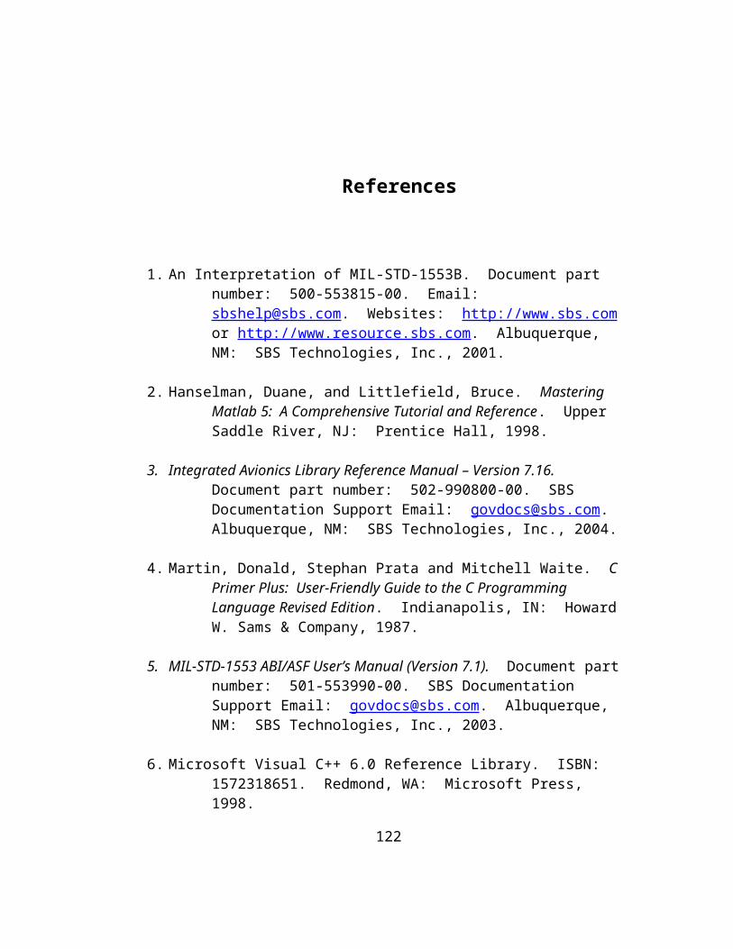
* Abstract: * Initializes 1553 card and variables. * Defines the BC chain program. * Starts the IO bus operation. * Clears initial application and firmware buffers. */#define MDL_INITIALIZE_CONDITIONSstatic void mdlInitializeConditions(SimStruct *S){ /* Initialize exchange count. */ xCntExpected = 0;
/* Initialize the device. */ if (sbs_init_device(DEV_NUM, IQ_LENGTH, BMQ_LENGTH, FROM_FILE) == FAILURE) { ssPrintf("FAILURE! %s\n", sbs_read_error()); ssSetStopRequested(S, true); return; }
/* Initialize BC program chain. */ status = SUCCESS; status *= m1553_add_link_to_chain(DEV_NUM, &GR); status *= m1553_add_link_to_chain(DEV_NUM, &SR1); status *= m1553_add_link_to_chain(DEV_NUM, &SR2); if (status == FAILURE) { ssPrintf("Failed to add links to chain! %s\n", sbs_read_error()); ssSetStopRequested(S, true); return; }
/* Start 1553 bus operation. */ status = sbs_start_io(DEV_NUM); if (status == FAILURE) { ssPrintf("FAILURE! %s\n", sbs_read_error()); ssSetStopRequested(S, true); return; }}
/** * Function: mdlInitializeSizes * Abstract: * Setup sizes of the various vectors. */static void mdlInitializeSizes(SimStruct *S){ DECL_AND_INIT_DIMSINFO(inputDimsInfo);
123

DECL_AND_INIT_DIMSINFO(outputDimsInfo); ssSetNumSFcnParams(S, NPARAMS); if (ssGetNumSFcnParams(S) != ssGetSFcnParamsCount(S)) { return; /* Parameter mismatch will be reported by Simulink */ }
ssSetNumContStates(S, NUM_CONT_STATES); ssSetNumDiscStates(S, NUM_DISC_STATES);
if (!ssSetNumInputPorts(S, NUM_INPUTS)) return; /*Input Port 0 */ ssSetInputPortWidth(S, 0, INPUT_0_WIDTH); ssSetInputPortDataType(S, 0, SS_DOUBLE); ssSetInputPortComplexSignal(S, 0, INPUT_0_COMPLEX); ssSetInputPortDirectFeedThrough(S, 0, INPUT_0_FEEDTHROUGH); ssSetInputPortRequiredContiguous(S, 0, 1); /*direct input signal access*/
/*Input Port 1 */ ssSetInputPortWidth(S, 1, INPUT_1_WIDTH); ssSetInputPortDataType(S, 1, SS_DOUBLE); ssSetInputPortComplexSignal(S, 1, INPUT_1_COMPLEX); ssSetInputPortDirectFeedThrough(S, 1, INPUT_1_FEEDTHROUGH); ssSetInputPortRequiredContiguous(S, 1, 1); /*direct input signal access*/
if (!ssSetNumOutputPorts(S, NUM_OUTPUTS)) return; /*Output Port 0 */ ssSetOutputPortWidth(S, 0, OUTPUT_0_WIDTH); ssSetOutputPortDataType(S, 0, SS_BOOLEAN); ssSetOutputPortComplexSignal(S, 0, OUTPUT_0_COMPLEX); /*Output Port 1 */ ssSetOutputPortWidth(S, 1, OUTPUT_1_WIDTH); ssSetOutputPortDataType(S, 1, SS_DOUBLE); ssSetOutputPortComplexSignal(S, 1, OUTPUT_1_COMPLEX);
ssSetNumSampleTimes(S, 1); ssSetNumRWork(S, 0); ssSetNumIWork(S, 0); ssSetNumPWork(S, 0); ssSetNumModes(S, 0); ssSetNumNonsampledZCs(S, 0);
/** * Added SS_OPTION_CALL_TERMINATE_ON_EXIT to force call to * mdlTerminate to close the 1553 card device. */ ssSetOptions(S, (SS_OPTION_EXCEPTION_FREE_CODE | SS_OPTION_USE_TLC_WITH_ACCELERATOR | SS_OPTION_WORKS_WITH_CODE_REUSE | SS_OPTION_CALL_TERMINATE_ON_EXIT));
124

}
#define MDL_SET_INPUT_PORT_DIMENSION_INFOvoid mdlSetInputPortDimensionInfo(SimStruct *S, int portIndex, const DimsInfo_T *dimsInfo){ DECL_AND_INIT_DIMSINFO(portDimsInfo); int_T dims[2] = { OUTPUT_0_WIDTH, 1 }; bool frameIn = (ssGetInputPortFrameData(S, 0) == FRAME_YES);
ssSetInputPortDimensionInfo(S, 0, dimsInfo);
if (ssGetOutputPortNumDimensions(S, 0) == (-1)) { /* the output port has not been set */ portDimsInfo.width = OUTPUT_0_WIDTH; portDimsInfo.numDims = frameIn ? 2 : 1; portDimsInfo.dims = frameIn ? dims : &portDimsInfo.width; ssSetOutputPortDimensionInfo(S, 0, &portDimsInfo); }}
#define MDL_SET_OUTPUT_PORT_DIMENSION_INFOvoid mdlSetOutputPortDimensionInfo(SimStruct *S, int_T portIndex, const DimsInfo_T *dimsInfo){ DECL_AND_INIT_DIMSINFO(portDimsInfo); int_T dims[2] = { OUTPUT_0_WIDTH, 1 }; bool frameOut = (ssGetOutputPortFrameData(S, 0) == FRAME_YES);
ssSetOutputPortDimensionInfo(S, 0, dimsInfo);
if (ssGetInputPortNumDimensions(S, 0) == (-1)) { /* the input port has not been set */ portDimsInfo.width = INPUT_0_WIDTH; portDimsInfo.numDims = frameOut ? 2 : 1; portDimsInfo.dims = frameOut ? dims : &portDimsInfo.width; ssSetInputPortDimensionInfo(S, 0, &portDimsInfo); }}
#define MDL_SET_DEFAULT_PORT_DIMENSION_INFOstatic void mdlSetDefaultPortDimensionInfo(SimStruct *S){ DECL_AND_INIT_DIMSINFO(portDimsInfo); int_T dims[2] = { INPUT_0_WIDTH, 1 }; bool frameIn = ssGetInputPortFrameData(S, 0) == FRAME_YES;
/* Neither the input nor the output ports have been set */
portDimsInfo.width = INPUT_0_WIDTH;
125

portDimsInfo.numDims = frameIn ? 2 : 1; portDimsInfo.dims = frameIn ? dims : &portDimsInfo.width; if (ssGetInputPortNumDimensions(S, 0) == (-1)) { ssSetInputPortDimensionInfo(S, 0, &portDimsInfo); } portDimsInfo.width = OUTPUT_0_WIDTH; dims[0] = OUTPUT_0_WIDTH; if (ssGetOutputPortNumDimensions(S, 0) == (-1)) { ssSetOutputPortDimensionInfo(S, 0, &portDimsInfo); } return;}
# define MDL_SET_INPUT_PORT_FRAME_DATAstatic void mdlSetInputPortFrameData(SimStruct *S, int_T port, Frame_T frameData){ ssSetInputPortFrameData(S, port, frameData);}
/** * Function: mdlInitializeSampleTimes * Abstract: * Specify the sample time. Inherited in our case. */static void mdlInitializeSampleTimes(SimStruct *S){ ssSetCallSystemOutput(S, 0); ssSetSampleTime(S, 0, SAMPLE_TIME_0); ssSetOffsetTime(S, 0, 0.0);}
#define MDL_SET_INPUT_PORT_DATA_TYPEstatic void mdlSetInputPortDataType(SimStruct *S, int port, DTypeId dType){ ssSetInputPortDataType(S, 0, dType);}
#define MDL_SET_OUTPUT_PORT_DATA_TYPEstatic void mdlSetOutputPortDataType(SimStruct *S, int port, DTypeId dType){ ssSetOutputPortDataType(S, 0, dType);}
#define MDL_SET_DEFAULT_PORT_DATA_TYPESstatic void mdlSetDefaultPortDataTypes(SimStruct *S){ ssSetInputPortDataType (S, 0, SS_DOUBLE);
126

ssSetOutputPortDataType(S, 0, SS_DOUBLE);}
/** * Function: mdlOutputs * Abstract: * Check to see if a new set of sensor readings is * available on the vehicle sim. This is done by * reading a message from rt1sa1t while it is not * busy and checking the next expected count. * * Once a reading with the expected count is received, * trigger the FS block to calculate the corresponding * commands and send them back to the vehicle sim's receive * buffers (rt1sa2r and rt1sa3r). */static void mdlOutputs(SimStruct *S, int_T tid){ const real_T *u0 = (const real_T*) ssGetInputPortSignal(S,0); const real_T *u1 = (const real_T*) ssGetInputPortSignal(S,1); boolean_T *y0 = (boolean_T *) ssGetOutputPortRealSignal(S,0); real_T *y1 = (real_T *) ssGetOutputPortRealSignal(S,1);
int i, j; /* Used as indices into arrays. */ int iIdx; /* Block input index */ int oIdx; /* Block output index */ int bIdx; /* Buffer index */ int xCntRcvd; /* Stores xchange cnt received from Plant sim. */ SBS16 *ptr; /* To build doubles from 4 16-bit 1553 words. */ SBS16 grCSumRcv; /* Stores csum rcvd. on mes. from Plant sim. */ SBS16 grCSum; /* Stores calculated csum for rcvd. reading. */ SBS16 sr1CSum; /* Calculated csum for 1st FS cmd. mes. */ SBS16 sr2CSum; /* Calculated csum for 2nd FS cmd. mes. */ SBS_STATUS_BLOCK_TYPE linkStatus; /* Checks the RT busy bit. */ SBS16 rBuffer[BUF_SIZE]; /* Rcv buffer for GR (Get Reading). */ SBS16 t1Buffer[BUF_SIZE]; /* Xmit buff 1 for SR1 - 1st part. */ SBS16 t2Buffer[BUF_SIZE]; /* Xmit buff 2 for SR2 - 2nd part. */
/* Stop the bus controller when all Plant sim steps have been completed. Finish the last step before stopping. */ if (xCntExpected >= MAX_STEPS) ssSetStopRequested(S, true);
/* Wait while RT is busy. */ do { /* Make sure the chain has completed before re-calling it. */ while (LL_get_ram(DEV_NUM, SBS_BCCPTR) != (SBS16) 0) {}
/* Start the BC program chain to get reading from rt1sa1t. */ status = SUCCESS; status *= m1553_load_chain(DEV_NUM, 1);
127

if (status == FAILURE) { ssPrintf("Failed while loading BC GR chain! %s\n", sbs_read_error()); ssSetStopRequested(S, true); return; }
/* Get the status of the RTBC cmd until it succeeds. */ while (m1553_read_link_status(DEV_NUM, GR.link_id, linkStatus) == FAILURE) {} } while(((SBS_STATUS_RESPONSE_TYPE *) linkStatus)->bits.busy == 1);
/* Busy bit is no longer set, RT is ready. Read buffer. */ grCSumRcv = 0x0000; wc = 0; wc = m1553_read_link_data(DEV_NUM, GR.link_id, GR.buff_id[0], rBuffer); if (wc == 0) { ssPrintf("Failed to get sensor reading from rt1sa1t! Stopping sim...\n"); ssSetStopRequested(S, true); return; }
/* Read the checksum word just received. */ grCSumRcv = rBuffer[CSUM_IDX]; /* Calculate the checksum that "should have" been received. */ grCSum = 0xFFFF; for (i = 0; i < (BUF_SIZE - 1); i++) { grCSum = grCSum ^ rBuffer[i]; } /* Read the new count received. */ ptr = (SBS16 *) &xCntRcvd; ptr[1] = rBuffer[COUNT_START]; ptr[0] = rBuffer[COUNT_END];
/* If BC gets the expected reading, process it. Otherwise, move to the next sim step and try again. The expected reading will have arrived when next expected count (xCntExpected) words are received on link buffer (GR). If so, trigger FS block and process the data. Once the sensor data count (xCntRcvd) and checksum word are the ones we are expecting (xCntExpected), forward the data to the FS block and call it to process it. */
128

if (((xCntRcvd == xCntExpected) && (grCSumRcv == grCSum))) { oIdx = 0; /* Output Index */ bIdx = 0; /* Buffer Index */ for (i = 0; i < DT_SIZE; i++) { ptr = (SBS16 *) &y1[oIdx++]; for (j = 0; j < WORDS_PER_DOUBLE; j++) { ptr[j] = rBuffer[bIdx++]; } } for (i = 0; i < DV_SIZE; i++) { ptr = (SBS16 *) &y1[oIdx++]; for (j = 0; j < WORDS_PER_DOUBLE; j++) { ptr[j] = rBuffer[bIdx++]; } } /* Note, elements 2 and 3 only */ for (i = 1; i < GI_SIZE; i++) { y1[oIdx++] = rBuffer[bIdx++]; } /* Note, elements 0 and 1 only */ for (i = 0; i < GID_SIZE; i++) { y1[oIdx++] = rBuffer[bIdx++]; }
/* Call FS triggered subsystem. */ if (!ssCallSystemWithTid(S, 0, tid)) { ssPrintf("Failed triggering the FS subsystem to run!\n"); ssSetStopRequested(S, true); return; } else { /* After successful execution of the FS triggered subsystem, control returns here. The output of the FS block should now be waiting to be read on the input to this block. Populate the transmit buffers with command data, count number and checksum.
Load transmit link buffers (SR1 and SR2). Use xCntRcvd so that the sensor data and command response have the same count number. */
/* Load SR1 application buffer first. */ iIdx = 0; /* Reset to begin reading FS response
129

from block's input. */ bIdx = 0; /* Reset to begin loading buffer. */ /* First 18 words from FS result. */ for (i = 0; i <= CMD_DATA_END; i++) { t1Buffer[bIdx++] = (SBS16) u0[iIdx++]; } /* Move buffer index to count start word. */ bIdx = COUNT_START; ptr = (SBS16 *) &xCntRcvd; /* ptr[1] before ptr[0] because of Little Endian. */ t1Buffer[bIdx++] = ptr[1]; t1Buffer[bIdx++] = ptr[0]; /* Generate checksum for SR1 transmit buffer. Note "(BUF_SIZE - 1)" is used because checksum field itself is not included in the calculation. */ sr1CSum = 0xFFFF; for (i = 0; i < (BUF_SIZE - 1); i++) { sr1CSum = sr1CSum ^ t1Buffer[i]; } /* Store checksum word. */ t1Buffer[CSUM_IDX] = (SBS16) sr1CSum;
/* Write to SR1 firmware link buffer. */ wc = 0; wc = m1553_write_link_data(DEV_NUM, SR1.link_id, SR1.buff_id[0], t1Buffer); if (wc == 0) { ssPrintf("Failed to write 1st part of FS response! Stopping sim...\n"); ssSetStopRequested(S, true); return; }
/* Load SR2 application buffer: */ bIdx = 0; /* Reset to begin loading buffer. */ /* Last 18 words from FS result. */ for (i = 0; i <= CMD_DATA_END; i++) { t2Buffer[bIdx++] = (SBS16) u0[iIdx++]; } /* Move buffer index to count start word. */ bIdx = COUNT_START; ptr = (SBS16 *) &xCntRcvd; /* ptr[1] before ptr[0] because of Little Endian. */ t2Buffer[bIdx++] = ptr[1]; t2Buffer[bIdx++] = ptr[0]; /* Generate checksum for SR2 transmit buffer. Note "(BUF_SIZE - 1)" is used because checksum field itself is not included in the calculation. */
130

sr2CSum = 0xFFFF; for (i = 0; i < (BUF_SIZE - 1); i++) { sr2CSum = sr2CSum ^ t2Buffer[i]; } /* Store checksum word. */ t2Buffer[CSUM_IDX] = (SBS16) sr2CSum;
/* Write to SR2 firmware link buffer. */ wc = 0; wc = m1553_write_link_data(DEV_NUM, SR2.link_id, SR2.buff_id[0], t2Buffer); if (wc == 0) { ssPrintf("Failed to write 2nd part of FS response! Stopping sim...\n"); ssSetStopRequested(S, true); return; }
/* Make sure that the chain has completed executing before loading it again. */ while (LL_get_ram(DEV_NUM, SBS_BCCPTR) != (SBS16) 0) {}
/* Start the BC program chain to send the response to rt1sa2r and rt1sa3r. */ status = SUCCESS; status *= m1553_load_chain(DEV_NUM, 2); if (status == FAILURE) { ssPrintf("Failed while loading SR chain! %s\n", sbs_read_error()); ssSetStopRequested(S, true); return; } /* Increment xCntExpected to be used on next sim step. */ xCntExpected++; } } ucatbc_Outputs_wrapper(u0,u1,y0,y1);}
#undef MDL_UPDATE /* Change to #define to use the function */#if defined(MDL_UPDATE)/* Function: mdlUpdate * Abstract: * This function is called once for every major integration * time step. Discrete states are typically updated here, but * this function is useful for performing any tasks that should * only take place once per integration step. */static void mdlUpdate(SimStruct *S, int_T tid)
131

{ const real_T *u0 = (const real_T*) ssGetInputPortSignal(S,0); const real_T *u1 = (const real_T*) ssGetInputPortSignal(S,1); real_T *xD = ssGetDiscStates(S); boolean_T *y0 = (boolean_T *) ssGetOutputPortRealSignal(S,0); real_T *y1 = (real_T *) ssGetOutputPortRealSignal(S,1); ucatbc_Update_wrapper(u0,u1,y0,y1);}#endif /* MDL_UPDATE */
#undef MDL_DERIVATIVES /* Change to #define to use function */#if defined(MDL_DERIVATIVES)/* Function: mdlDerivatives * Abstract: * In this function, you compute the S-function block's * derivatives. The derivatives are placed in the derivative * vector, ssGetdX(S). */static void mdlDerivatives(SimStruct *S){ const real_T *u0 = (const real_T*) ssGetInputPortSignal(S,0); const real_T *u1 = (const real_T*) ssGetInputPortSignal(S,1); real_T *dx = ssGetdX(S); real_T *xC = ssGetContStates(S); boolean_T *y0 = (boolean_T *) ssGetOutputPortRealSignal(S,0); real_T *y1 = (real_T *) ssGetOutputPortRealSignal(S,1); ucatbc_Derivatives_wrapper(u0,u1,y0,y1, dx);}#endif /* MDL_DERIVATIVES */
/** * Function: mdlTerminate * Abstract: * Stop program chain, bus IO and ABI-PCI-1 device. */static void mdlTerminate(SimStruct *S){ m1553_stop_chain(DEV_NUM); sbs_stop_io(DEV_NUM); ssPrintf("# of sensor data/command exchanges = %d\n", xCntExpected); sbs_close_device(DEV_NUM); return;}#ifdef MATLAB_MEX_FILE /* Is this file being compiled as a MEX-file? */#include "simulink.c" /* MEX-file interface mechanism */#else#include "cg_sfun.h" /* Code generation registration function */#endif
132

/*================================================================= * File: ucatrt.c * * --- THIS FILE GENERATED BY S-FUNCTION BUILDER: 2.0 --- * * This file is an S-function produced by the S-Function * Builder which only recognizes certain fields. Changes made * outside these fields will be lost the next time the block is * used to load, edit, and resave this file. This file will be * overwritten by the S-function Builder block. If you want to * edit this file by hand, you must change it only in the area * defined as: * * %%%-SFUNWIZ_defines_Changes_BEGIN * #define NAME 'replacement text' * %%% SFUNWIZ_defines_Changes_END * * DO NOT change NAME--Change the 'replacement text' only. * * For better compatibility with the Real-Time Workshop, the * "wrapper" S-function technique is used. This is discussed * in the Real-Time Workshop User's Manual in the Chapter titled, * "Wrapper S-functions". * * --------------------------------------------------------------- * | See matlabroot/simulink/src/sfuntmpl_doc.c for a more detailed * | template | * --------------------------------------------------------------- * Created: Wed Jul 28 16:23:51 2004 * Modified thereafter by Elias Victor for: * NASA, Kennedy Space Center AND Florida Tech. (FIT) * Mission Analysis Branch School of Electrical and * Computer Engineering * *================================================================= * * The following copyright notice is included herein because this * S-function uses the SBS Technologies API to communicate with an * ABI-PCI-1 interface board to transmit and receive messages or * packets via a 1553 avionics bus. * *================================================================= * Copyright (c) 2001 by SBS Technologies, Inc. * 2400 Louisiana Blvd., NE * AFC Building 5, Suite 600 * Albuquerque, New Mexico 87110 * Technical support (toll free) * 877-TECHSBS (877-832-4727) *================================================================= * SBS INTEGRATED AVIONICS LIBRARY Version 7.16 * Last Modified 16 Apr 03 *=================================================================
133

* This software is Licensed to be used only in connection with a * SBS adapter. If this Software is merged with any other software * program it is subject to the terms and conditions of this * license. If you copy this software, you must reproduce and * include all copyright notices and any other proprietary rights * notices. For full information on the License Agreement please * see the included License.txt file. *===============================================================*/
#define S_FUNCTION_NAME ucatrt#define S_FUNCTION_LEVEL 2
/*<<<<<<<<<<<<<<<<<<<<<<<<<<<<<<<<<<<<<<<<<<<<<<<<<<<<<<<<<<<<<<<*//* %%%-SFUNWIZ_defines_Changes_BEGIN --- EDIT HERE TO _END */
#define NUM_INPUTS 2
/* Input Port 0 */#define IN_PORT_0_NAME u0#define INPUT_0_WIDTH 10#define INPUT_DIMS_0_COL 1#define INPUT_0_DTYPE real_T#define INPUT_0_COMPLEX COMPLEX_NO#define IN_0_FRAME_BASED FRAME_NO#define IN_0_DIMS 1-D#define INPUT_0_FEEDTHROUGH 1
/* Input Port 1 */#define IN_PORT_1_NAME u1#define INPUT_1_WIDTH 1#define INPUT_DIMS_1_COL 1#define INPUT_1_DTYPE real_T#define INPUT_1_COMPLEX COMPLEX_NO#define IN_1_FRAME_BASED FRAME_NO#define IN_1_DIMS 1-D#define INPUT_1_FEEDTHROUGH 1
#define NUM_OUTPUTS 1
/* Output Port 0 */#define OUT_PORT_0_NAME y0#define OUTPUT_0_WIDTH 36#define OUTPUT_DIMS_0_COL 1#define OUTPUT_0_DTYPE real_T#define OUTPUT_0_COMPLEX COMPLEX_NO#define OUT_0_FRAME_BASED FRAME_NO#define OUT_0_DIMS 1-D
#define NPARAMS 0
#define SAMPLE_TIME_0 INHERITED_SAMPLE_TIME#define NUM_DISC_STATES 0
134

#define DISC_STATES_IC [0]#define NUM_CONT_STATES 0#define CONT_STATES_IC [0]
#define SFUNWIZ_GENERATE_TLC 1#define SOURCEFILES "ll_win32.c parser.c dev_mgmt.c 1553_dm.c 1553_rtm.c"#define PANELINDEX 6#define SFUNWIZ_REVISION 2.0
/* %%%-SFUNWIZ_defines_Changes_END --- EDIT HERE TO _BEGIN *//*<<<<<<<<<<<<<<<<<<<<<<<<<<<<<<<<<<<<<<<<<<<<<<<<<<<<<<<<<<<<<<<*/
#include "simstruc.h"
extern void ucatrt_Outputs_wrapper(const real_T *u0, const real_T *u1, real_T *y0);
extern void ucatrt_Update_wrapper(const real_T *u0, const real_T *u1, const real_T *y0);
extern void ucatrt_Derivatives_wrapper(const real_T *u0, const real_T *u1, const real_T *y0, real_T *dx);
/*@@@@@ Begin global 1553 declarations to be used by multiple functions. @@@@@*/
#include "1553_inc.h"#define DEV_NUM 1 /* Always "1", only have PCI card installed. */#define IQ_LENGTH 4 /* Irq queue length - minimum value is 4. */#define BMQ_LENGTH 1000 /* Bus monitoring queue length. */#define BUF_SIZE 32 /* Buffers store 32 16-bit words. */
SBS_EXCEPTION status; /* Stores returning SUCCESS or FAILURE. */int wc; /* Stores returning word cnt when read/writ. mes. buffs. */
/* RT/SA's to be allocated: SR (Send Reading) CR (Receive Command Response) */SBS_SA_INFO_TYPE SR = {1, 1, SBS_XMIT, 0, 1, NULL, 0};SBS_SA_INFO_TYPE CR1 = {1, 2, SBS_RCV, 0, 1, NULL, 0};SBS_SA_INFO_TYPE CR2 = {1, 3, SBS_RCV, 0, 1, NULL, 0};
/*@@@@@ End global 1553 declarations. @@@@@*/
/*@@@@@ Begin global UCAT declarations. @@@@@*/
/* Define the size of I/O signals to/from 1553 subsystem block. */
135

#define CMD_SIZE 36 /* Commands */#define DT_SIZE 3 /* Delta Theta */#define DV_SIZE 3 /* Delta Velocity */#define GI_SIZE 3 /* Gyro Input */#define GID_SIZE 2 /* Gyro Input Discrete */
#define RESET 0x0000 /* Used to reset 1553 words on buffers. */#define WORDS_PER_DOUBLE 4 /* 4 1553 words store double value. */#define WAIT_CNT 2000000 /* Counter to trigger sim stop when exhausted. Can be increased to allow the operator more time to start the FS simulation. */
/* Define important message indices. */#define CMD_DATA_END 17 /* End of cmd words for CR1, CR2 buffers.*/#define COUNT_START 29 /* Xchange cnt words begins at word 29. */#define COUNT_END 30 /* Xchange cnt words end at word 30. */#define CSUM_IDX 31 /* Word idx where csum field is expected.*/
/* To keep track of num of readings transmitted to UCATFS. */int xCntTransmitted;
/* Used to display startup messages to operator. */int cnt0;int cnt1;
/*@@@@@ End UCAT specific declarations. @@@@@*/
/*====================* * S-function methods * *====================*/
/** * Function: mdlInitializeConditions * Abstract: * Initializes 1553 card and variables. * Defines the RT Subaddress buffers. * Starts the IO bus operation. * Clears application buffers. */#define MDL_INITIALIZE_CONDITIONSstatic void mdlInitializeConditions(SimStruct *S){ /* Initialize exchange count. */ xCntTransmitted = 0;
/* Initialize counts for startup messages. */ cnt0 = 0; cnt1 = 0;
/* Initialize the device. */ if (sbs_init_device(DEV_NUM, IQ_LENGTH, BMQ_LENGTH, FROM_FILE)
136

== FAILURE) { ssPrintf("FAILURE! %s\n", sbs_read_error()); ssSetStopRequested(S, true); return; } /* Define the simulated RT subaddresses (SAs). */ status = SUCCESS; status *= m1553_define_rt_sa(DEV_NUM, &SR); status *= m1553_define_rt_sa(DEV_NUM, &CR1); status *= m1553_define_rt_sa(DEV_NUM, &CR2); if (status == FAILURE) { ssPrintf("FAILURE! %s\n", sbs_read_error()); sbs_close_device(DEV_NUM); ssSetStopRequested(S, true); return; }
/* Ready to communicate. */ if (sbs_start_io(DEV_NUM) == FAILURE) { ssPrintf("FAILURE! %s\n", sbs_read_error()); ssSetStopRequested(S, true); return; }}
/** * Function: mdlInitializeSizes * Abstract: * Setup sizes of the various vectors. */static void mdlInitializeSizes(SimStruct *S){ DECL_AND_INIT_DIMSINFO(inputDimsInfo); DECL_AND_INIT_DIMSINFO(outputDimsInfo); ssSetNumSFcnParams(S, NPARAMS); if (ssGetNumSFcnParams(S) != ssGetSFcnParamsCount(S)) { return; /* Parameter mismatch will be reported by Simulink */ }
ssSetNumContStates(S, NUM_CONT_STATES); ssSetNumDiscStates(S, NUM_DISC_STATES);
if (!ssSetNumInputPorts(S, NUM_INPUTS)) return; /*Input Port 0 */ ssSetInputPortWidth(S, 0, INPUT_0_WIDTH); ssSetInputPortDataType(S, 0, SS_DOUBLE); ssSetInputPortComplexSignal(S, 0, INPUT_0_COMPLEX);
137

ssSetInputPortDirectFeedThrough(S, 0, INPUT_0_FEEDTHROUGH); ssSetInputPortRequiredContiguous(S, 0, 1); /*direct input signal access */
/*Input Port 1 */ ssSetInputPortWidth(S, 1, INPUT_1_WIDTH); ssSetInputPortDataType(S, 1, SS_DOUBLE); ssSetInputPortComplexSignal(S, 1, INPUT_1_COMPLEX); ssSetInputPortDirectFeedThrough(S, 1, INPUT_1_FEEDTHROUGH); ssSetInputPortRequiredContiguous(S, 1, 1); /*direct input signal access*/
if (!ssSetNumOutputPorts(S, NUM_OUTPUTS)) return; ssSetOutputPortWidth(S, 0, OUTPUT_0_WIDTH); ssSetOutputPortDataType(S, 0, SS_DOUBLE); ssSetOutputPortComplexSignal(S, 0, OUTPUT_0_COMPLEX); ssSetNumSampleTimes(S, 1); ssSetNumRWork(S, 0); ssSetNumIWork(S, 0); ssSetNumPWork(S, 0); ssSetNumModes(S, 0); ssSetNumNonsampledZCs(S, 0);
/** * Added SS_OPTION_CALL_TERMINATE_ON_EXIT to force call to * mdlTerminate to close the 1553 card device. */ ssSetOptions(S, (SS_OPTION_EXCEPTION_FREE_CODE | SS_OPTION_USE_TLC_WITH_ACCELERATOR | SS_OPTION_WORKS_WITH_CODE_REUSE | SS_OPTION_CALL_TERMINATE_ON_EXIT));}
# define MDL_SET_INPUT_PORT_FRAME_DATAstatic void mdlSetInputPortFrameData(SimStruct *S, int_T port, Frame_T frameData){ ssSetInputPortFrameData(S, port, frameData);}
/** * Function: mdlInitializeSampleTimes * Abstract: * Specify the sample time. Note that this was set * to 0.02 sec since that was the sample time used * by the non-1553 version of the UCAT simulation's * FS S-Function. */static void mdlInitializeSampleTimes(SimStruct *S){ ssSetSampleTime(S, 0, 0.02); /* Set to execute every 20ms. */ ssSetOffsetTime(S, 0, 0.0);
138

}
#define MDL_SET_INPUT_PORT_DATA_TYPEstatic void mdlSetInputPortDataType(SimStruct *S, int port, DTypeId dType){ ssSetInputPortDataType( S, 0, dType);}
#define MDL_SET_OUTPUT_PORT_DATA_TYPEstatic void mdlSetOutputPortDataType(SimStruct *S, int port, DTypeId dType){ ssSetOutputPortDataType(S, 0, dType);}
#define MDL_SET_DEFAULT_PORT_DATA_TYPESstatic void mdlSetDefaultPortDataTypes(SimStruct *S){ ssSetInputPortDataType( S, 0, SS_DOUBLE); ssSetOutputPortDataType(S, 0, SS_DOUBLE);}
/** * Function: mdlOutputs * Abstract: * Gets sensor data from vehicle subsystems every 20ms of * simTime and writes it to firmware buffer rt1sa1t for * transmission to FS system. * * Waits for the appropriate command response from FS and * forwards it to the next simulation block. */static void mdlOutputs(SimStruct *S, int_T tid){ const real_T *u0 = (const real_T*) ssGetInputPortSignal(S,0); const real_T *u1 = (const real_T*) ssGetInputPortSignal(S,1); real_T *y0 = (real_T *) ssGetOutputPortRealSignal(S,0);
int i, j; /* Used as indices into arrays. */ int stopSim; /* Used to stop sim when there is no response. */ int iIdx; /* Block input index */ int oIdx; /* Block output index */ int bIdx; /* Buffer index */ int r1XCntRcvd; /* Stores Xchange cnt rcvd from BC SR1 mes. */ int r2XCntRcvd; /* Stores Xchange cnt rcvd from BC SR2 mes. */ SBS16 *ptr; /* Used to brake up doubles to store in buffer. */ SBS16 srCSum;/* Used to store calculated csum for reading. */ SBS16 cr1CSumRcvd; /* Received csum for message on rt1sa2r. */ SBS16 cr2CSumRcvd; /* Received csum for message on rt1sa3r. */ SBS16 cr1CSum; /* Stores calculated csum for BC SR1 mes. */ SBS16 cr2CSum; /* Stores calculated csum for BC SR2 mes. */
139

SBS_STATUS_RESPONSE_TYPE stsWord; /* Used to load RT1 status word to set and reset the RT’s busy-bit. */ SBS16 tBuffer[BUF_SIZE]; /* Xmit buf. for SR (Send Reading). */ SBS16 r1Buffer[BUF_SIZE]; /* Rcv buf. for CR1 (Cmd Resp. 1) */ SBS16 r2Buffer[BUF_SIZE]; /* Rcv buf. for CR2 (Cmd Resp. 2) */
/* Read sensor data from plant subsystems and store in transmit buffer (6 doubles, 4 shorts). */ iIdx = 0; /* Input Index */ bIdx = 0; /* Reset to begin loading buffer. */ for (i = 0; i < DT_SIZE; i++) /* 3 doubles */ { ptr = (SBS16 *) &u0[iIdx++]; for (j = 0; j < WORDS_PER_DOUBLE; j++) { tBuffer[bIdx++] = (SBS16) ptr[j]; } } for (i = 0; i < DV_SIZE; i++) /* 3 doubles */ { ptr = (SBS16 *) &u0[iIdx++]; for (j = 0; j < WORDS_PER_DOUBLE; j++) { tBuffer[bIdx++] = (SBS16) ptr[j]; } } /* Note, elements 2 and 3 only. */ for (i = 1; i < GI_SIZE; i++) /* 2 shorts */ { tBuffer[bIdx++] = (SBS16) u0[iIdx++]; } /* Note, elements 1 and 2 only. */ for (i = 0; i < GID_SIZE; i++) /* 2 shorts */ { tBuffer[bIdx++] = (SBS16) u0[iIdx++]; }
/* Sensor data count. */ bIdx = COUNT_START; ptr = (SBS16 *) &xCntTransmitted; /* ptr[1] before ptr[0] because of Little Endian. */ tBuffer[bIdx++] = ptr[1]; tBuffer[bIdx++] = ptr[0]; /* Generate checksum word. */ srCSum = 0xFFFF; for (i = 0; i < (BUF_SIZE - 1); i++) { srCSum = srCSum ^ tBuffer[i]; } /* Store checksum word. */ tBuffer[bIdx] = srCSum;
140

/* Write sensor data to SR firmware transmit buffer. */ wc = -1; wc = m1553_write_sa_buffer(DEV_NUM, BUF_SIZE, SR.buff_id[0], tBuffer); if (wc == 0) { ssPrintf("Failed to write to rt1sa1t buffer! Stopping sim...\n"); ssSetStopRequested(S, true); return; }
/* Clear the busy bit on RT1's status word to signal to the BC that a new reading is available on rt1sa1t. */ stsWord.ushort = 0; stsWord.bits.rt_address = 1; /* RT1 */ stsWord.bits.busy = 0; status = SUCCESS; status *= m1553_load_status_word(DEV_NUM, 1, stsWord); if (status == FAILURE) { ssPrintf("Failed clearing RT1 status word busy bit.\n"); ssSetStopRequested(S, true); return; }
/* Wait until the corresponding response from FS is received. This will be true when the response counts are equal to the previous xCntTransmitted. And when the checksum fields of the command responses received are the same. */ stopSim = 0; r1XCntRcvd = -1; r2XCntRcvd = -1; cr1CSum = 0xFFFF; cr2CSum = 0xFFFF; cr1CSumRcvd = 0x0000; cr2CSumRcvd = 0x0000; while (!((r1XCntRcvd == xCntTransmitted) && (r2XCntRcvd == xCntTransmitted) && (cr1CSumRcvd == cr1CSum) && (cr2CSumRcvd == cr2CSum))) { if (stopSim == WAIT_CNT) { ssPrintf("Failed to receive response %d from FS! Stopping sim...\n", xCntTransmitted); ssSetStopRequested(S, true); return; } else { if ((xCntTransmitted == 0) && (cnt0 == 0)) {
141

ssPrintf("Waiting for initial response from UCATFS sim...\n"); ssPrintf("Press UCATFS \"Start Simulation\" button to begin...\n"); cnt0++; } else if ((xCntTransmitted == 1) && (cnt1 == 0)) { ssPrintf("1553 UCAT simulation in progress...\n"); cnt1++; } }
/* Read command response buffer 1. */ if (m1553_read_sa_buffer(DEV_NUM, CR1.buff_id[0], r1Buffer) > 0) { /* Store checksum received in buffer. */ cr1CSumRcvd = r1Buffer[CSUM_IDX];
/* Generate checksum from buffer just received. Note "(BUF_SIZE - 1)" is used because checksum word itself is not included in the calculation. */ cr1CSum = 0xFFFF; for (i = 0; i < (BUF_SIZE - 1); i++) { cr1CSum = cr1CSum ^ r1Buffer[i]; }
/* Read the count received rt1sa2r. ptr[1] before ptr[0] because of Little Endian. */ ptr = (SBS16 *) &r1XCntRcvd; ptr[1] = (SBS16) r1Buffer[COUNT_START]; ptr[0] = (SBS16) r1Buffer[COUNT_END]; }
/* Read command response buffer 2. */ if (m1553_read_sa_buffer(DEV_NUM, CR2.buff_id[0], r2Buffer) > 0) { /* Store CRC received in buffer. */ cr2CSumRcvd = r2Buffer[CSUM_IDX];
/* Generate checksum from buffer just received. Note "(BUF_SIZE - 1)" is used because checksum word itself is not included in the calculation. */ cr2CSum = 0xFFFF; for (i = 0; i < (BUF_SIZE - 1); i++) { cr2CSum = cr2CSum ^ r2Buffer[i]; }
142

/* Read the count received on rt1sa3r. ptr[1] before ptr[0] because of Little Endian. */ ptr = (SBS16 *) &r2XCntRcvd; ptr[1] = (SBS16) r2Buffer[COUNT_START]; ptr[0] = (SBS16) r2Buffer[COUNT_END]; }
stopSim++; }
/* Once we get here, the response from FS has been received. Stop FS from reading rt1sa1t by setting the busy bit. */ stsWord.ushort = 0; stsWord.bits.rt_address = 1; /* RT1 */ stsWord.bits.busy = 1; status = SUCCESS; status *= m1553_load_status_word(DEV_NUM, 1, stsWord); if (status == FAILURE) { ssPrintf("Failed while loading RT1 status word to set busy bit.\n"); ssSetStopRequested(S, true); return; }
/* Output command response data values. */ oIdx = 0;
for (bIdx = 0; bIdx <= CMD_DATA_END; bIdx++) { y0[oIdx++] = r1Buffer[bIdx]; } for (bIdx = 0; bIdx <= CMD_DATA_END; bIdx++) { y0[oIdx++] = r2Buffer[bIdx]; }
/* Increment xCountTransmitted to be used on next sim step. */ xCntTransmitted++;
ucatrt_Outputs_wrapper(u0,u1,y0);}
#undef MDL_UPDATE /* Change to #define to use the function */#if defined(MDL_UPDATE)/** * Function: mdlUpdate * Abstract: * This function is called once for every major integration * time step. Discrete states are typically updated here, * but this function is useful for performing any tasks that * should only take place once per integration step.
143

*/static void mdlUpdate(SimStruct *S, int_T tid){ const real_T *u0 = (const real_T*) ssGetInputPortSignal(S,0); const real_T *u1 = (const real_T*) ssGetInputPortSignal(S,1); real_T *xD = ssGetDiscStates(S); real_T *y0 = (real_T *)ssGetOutputPortRealSignal(S,0); ucatrt_Update_wrapper(u0,u1,y0);} #endif /* MDL_UPDATE */
#undef MDL_DERIVATIVES /* Change to #define to use function */#if defined(MDL_DERIVATIVES)/** * Function: mdlDerivatives * Abstract: * In this function, you compute the S-function block's * derivatives. The derivatives are placed in the derivative * vector, ssGetdX(S). */static void mdlDerivatives(SimStruct *S){ const real_T *u0 = (const real_T*) ssGetInputPortSignal(S,0); const real_T *u1 = (const real_T*) ssGetInputPortSignal(S,1); real_T *dx = ssGetdX(S); real_T *xC = ssGetContStates(S); real_T *y0 = (real_T *) ssGetOutputPortRealSignal(S,0); ucatrt_Derivatives_wrapper(u0,u1,y0,dx);}#endif /* MDL_DERIVATIVES */
/** * Function: mdlTerminate * Abstract: * Stop bus IO and 1553 ABI-PCI-1 device. */static void mdlTerminate(SimStruct *S){ sbs_stop_io(DEV_NUM); ssPrintf("# of sensor data/command exchanges = %d\n", xCntTransmitted); sbs_close_device(DEV_NUM); return;}#ifdef MATLAB_MEX_FILE /* Is this file being compiled as a MEX-file? */#include "simulink.c" /* MEX-file interface mechanism */#else#include "cg_sfun.h" /* Code generation registration function */#endif
144

Page intentionally left blank.
145

Appendix Csbs_dev.cfg Listing
This appendix shows the complete listing of the sbs_dev.cfg configuration file used by the SBS Integrated Avionics Library’s low level functions to access the ABI-PCI-1 1553 board device. Note that both UCATFS and UCATPLANT computer systems only had a single 1553 PCI board and that the firmware file (f040m2.dat) was loaded every time the simulations were initialized.
sbs_dev.cfg File Listing:;-------------------------[DEVICE=1]device_type=M1553_PCI_1dd_name=sbspci320firmware=f040m2.dat
146

Page intentionally left blank.
147

Appendix DSBS Copyright Notice
/*================================================================= * Copyright (c) 2001 by SBS Technologies, Inc. * 2400 Louisiana Blvd., NE * AFC Building 5, Suite 600 * Albuquerque, New Mexico 87110 * Technical support (toll free) * 877-TECHSBS (877-832-4727) *================================================================= * SBS INTEGRATED AVIONICS LIBRARY Version 7.16 * Last Modified 16 Apr 03 *================================================================= * This software is Licensed to be used only in connection with a * SBS adapter. If this Software is merged with any other software * program it is subject to the terms and conditions of this * license. If you copy this software, you must reproduce and * include all copyright notices and any other proprietary rights * notices. For full information on the License Agreement please * see the included License.txt file. *=================================================================
148

Page intentionally left blank.
149

Appendix E
150

151