mxr envelope filter kit building manual - effect pedal kits · mxr envelope filter kit building...
TRANSCRIPT

MXR Envelope Filter Kit Building Manual
Effect Pedal Kits: MXR Envelope Filter
One of the first builds of anybody getting into the DIY world is definitely the MXR Envelope Filter. This 100% analog circuit is an envelope filter. This kind of effect works like a wah, but instead of being controlled by the position of the pedal, the filter is controlled by how loud your playing is. The MXR Envelope Filter works great with almost any instrument you can think of (bass, guitar, keyboard…), and is a great effect if you want a funkier sound!
In this version of the MXR Envelope Filter, we’ve added a Reverse Switch so you can make the wah work the other way around. Usually, the filter would start highlighting the low frequencies and progressively go to higher frequencies as louder notes are played. Well, when turning on the Reverse Switch, the MXR Envelope Filter will initially highlight the highs and walk his way to the lower frequencies. It’s a cool mod that allows the MXR Envelope Filter have a complete different sound.

BOM (1/2) Resistors (31) Capacitors (13)
1 R1 3.3k 3 C1, C7, C10 100n
4 R2, R3, R12, R31 1M 4 C2, C5, C8, C9 47n
3 R4, R9, R11 200k 1 C3 560p (ceramic)
1 R5 240k 1 C4 470p (ceramic)
6 R6, R7, R8, R23, R25, R26 47k 1 C6 1n
1 R10 3.6k 1 C11 100p (ceramic)
1 R13 5.1M 1 C12 10p (ceramic)
2 R14, R19 10k 1 C13 47u (electrolytic)
1 R15 470k
4 R16, R17, R21, R22 11M
2 R18, R20 10M
3 R24, R27, R29 100k
1 R28 62k
1 R30 3k
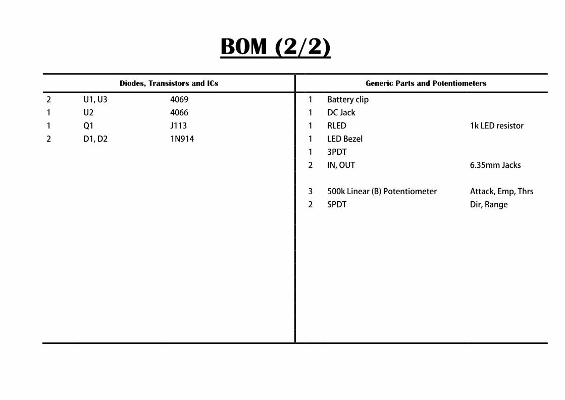
BOM (2/2) Diodes, Transistors and ICs Generic Parts and Potentiometers
2 U1, U3 4069 1 Battery clip
1 U2 4066 1 DC Jack
1 Q1 J113 1 RLED 1k LED resistor
2 D1, D2 1N914 1 LED Bezel
1 3PDT
2 IN, OUT 6.35mm Jacks
3 500k Linear (B) Potentiometer Attack, Emp, Thrs
2 SPDT Dir, Range

Component Placement

Board Layouts
3PDT PCB
Effect PCB

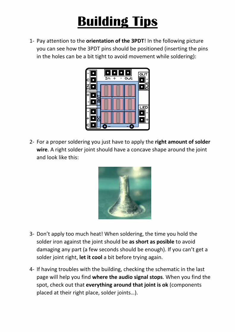
Building Tips 1- Pay attention to the orientation of the 3PDT! In the following picture
you can see how the 3PDT pins should be positioned (inserting the pins in the holes can be a bit tight to avoid movement while soldering):
2- For a proper soldering you just have to apply the right amount of solder wire. A right solder joint should have a concave shape around the joint and look like this:
3- Don’t apply too much heat! When soldering, the time you hold the solder iron against the joint should be as short as posible to avoid damaging any part (a few seconds should be enough). If you can’t get a solder joint right, let it cool a bit before trying again.
4- If having troubles with the building, checking the schematic in the last page will help you find where the audio signal stops. When you find the spot, check out that everything around that joint is ok (components placed at their right place, solder joints…).

Building Tips 5- Pay attention to the parts that have a polarity and make sure they are
connected as in the component placement picture:
- ICs (they have a small dot or indication that must fit the indication in the board
- Electrolytic capacitors (longer pin is connected to the “+” hole):
- Diodes (check for the mark and make it fit with the one in the PCB):
- Leds (longer pin is connected to the “+” hole)
- Transistors (inserted to fit the drawing in the PCB)

Building Tips 6- With the kit we include plastic PCB supports with an adhesive bottom. You
can use them to anchor the PCB to your enclosure for a better stability. Just insert the PCB support tip into the 3.5mm holes and remove the adhesive protective film.
To avoid any issue always check the latest building manual. Use the pictures only as a reference! Colors/shapes of wires, PCB or parts can change slightly,
this doesn’t affect their functionality in any way.
Always double check part polarity, resistor and capacitor values, potentiometer placement, IC orientation… before soldering.

Schematic