mxp-225 v-belt tension for elevation drive motor ... this mxp-225 double sided planer is specially...
TRANSCRIPT

MXP-225
EXTREMA MACHINERY COMPANY, INC. ALBANY, LOUISIANA 70711 (877) 398-7362 FAX (225) 567-2966

1
TABLE OF CONTENTS Preface 3 Features of the Machine 3 Unpacking & Checking Contents 3 Shipping & Receiving Instructions 4 Standard Accessories 4 Installation Site 4 Installation Dimensions 5 Lifting the Machine 5 Installing the Machine 6 Connecting Power Source Wires 7 Connecting the Power Wires 7 Connecting the Dust Collection System 8 General Safety Rules 9 Electrical Safety Rules 10 Warning Label Locations 11 Warning Label 12 Safety Instructions Label 12 Specifications 13 Legend of the Machine 14 Electrical Control Panel 15 Function Description for Electrical Control Panel 16 Safety Protection Switch 18 Upper & Lower Limit Switches for Pressure Mechanism 18 Pressure Mechanism Elevation Control 18 Electric Supply Connection 19 Current Consumption for Major Electric Parts 20 Initial Cleaning & Lubrication 20 Identification Before Operation 20 Starting Procedures for the Machine 21 Methods to Stop the Machine 21 Emergency Stop Switch 21 Lubricator 22 Manual Oil Feeding 22 Setting Time of Auto Oil Feeding 22 Automatic Lubricator 23 Hand Oiler 24 Control Panel of Digital Controller 24 Automatic Start of Digital Controller 24 Setup Upper Cutterhead with Pressure Mechanism Height 25 Wood Thickness Fast Setup 25 Adjust Feed Roller Pressure 25 Adjust Thickness of Plane for Upper & Lower Cutterhead 26 Upper & Lower Cutterhead Leveling Adjustment 26 Adjusting Feed Speed 27 How to Select Planer Knives 27 Planing Guide 27

2
Replacing the Planer Knives 28 Safety Rules for Maintenance 28 Adjust Feed Roller Height & Leveling 29 Adjust V-Belt Tension for Upper Cutterhead 29 Adjust V-Belt Tension for Lower Cutterhead 30 Adjust Transmission Chain Tension 30 Adjust V-Belt Tension for Elevation Drive Motor 30 Adjust Hold Down Pressure for Spike Conveyor 31 Adjust Tension of Spike Conveyor 31 Adjust Gear Box Chain Tension 31 Lubrication Locations 32 Lubrication Instructions 32 Electric Supply Connection 33 Ordering the Replacement Parts 35 Parts List 36 Digital Controller Operation Instructions/User Manual Attached

3
PREFACE This MXP-225 Double Sided Planer is specially designed and improved for providing the extraordinary outstanding performance. It also provides high productivity. Built with patented Cutterhead removing design for convenient knife replacement. Outstanding features include sectional outfeed rollers for feeding work pieces. This operation manual describes machine operation and maintenance instructions. Read the operation manual thoroughly before installing and operating the machine. Understand the correct operations of the machine for developing its top performance and preventing machine damage caused by incorrect operations. Parts lists are provided at the final part in this operation manual for reference while in repairing or replacing parts. Features of the Machine: 1. Suitable for cutting heavy, wide long, and moisturized wood. 2. Eliminated the conventional knife replacement method, this machine features patented, and
easy knife replacement for upper and lower cutterheads. 3. Extremely heavy cutting capability up to 28mm in a feed. 4. High planing speed 36 meters per minute. 5. Powerful sectional feed rollers. 6. Digital controller provides convenient and accurate elevation control for feed rollers. 7. Patented synchronized motion for upper and lower feed rollers ensuring smoothness of
work piece feeding. 8. Air loaded work piece pressure system provides stable and smooth feeding performance. 9. Circulating lubrication system saves oil consumption. Again, we appreciate it very much for your purchase of this machine. We will strive hard to design and manufacture the high performance machines to meet your requirements. If you have any questions or suggestions, please feel free to inform us for our future reference in machine design and improvement. UNPACKING & CHECKING CONTENTS The machine has been well packed at the manufacturer’s factory and shipped in good condition. The machine is shipped in one wooden pallet. Upon receiving the machine, carefully unpack it and check all items as according to the packing list. If you find any part is missed or damaged, contact immediately your local distributor or the manufacturer of the machine. Do not attempt to operate the machine until the missing parts are obtained and are installed correctly.

4
SHIPPING & RECEIVING INSTRUCTIONS This machine has been carefully inspected and tested before packing. It was delivered in good condition and was shipped in one wooden pallet. When receiving this machine, inspect the wooden pallet and check to see if there is any damage on the wooden pallet. Then check the machine model and all items as according to the packing list. If there is any damage on the machine or missing parts, report to your local distributor or the machine manufacturer immediately. STANDARD ACCESSORIES The machine comes with the following accessories:
1. Tool Box 1-pc 2. Lubricator 1-pc 3. Hex. Wrench Metric Sizes 1-set 4. Open End Wrench 11 x 13 1-pc 5. Open End Wrench 12 x 14 1-pc 6. Open End Wrench 17 x 19 1-pc 7. Box End Wrench 30mm 1-pc 8. Box End Wrench 24mm 1-pc 9. Shaft Coupler Rubber #122 2-pcs 10. Knife Spring 12-pcs 11. Knife Setting Gauge 2-pcs 12. Steel Pad 4-pcs
INSTALLATION SITE Do not install the machine in a dangerous environment. Do not use the machine in a damp or wet location or expose to rain. Keep the work area well lighted.
5
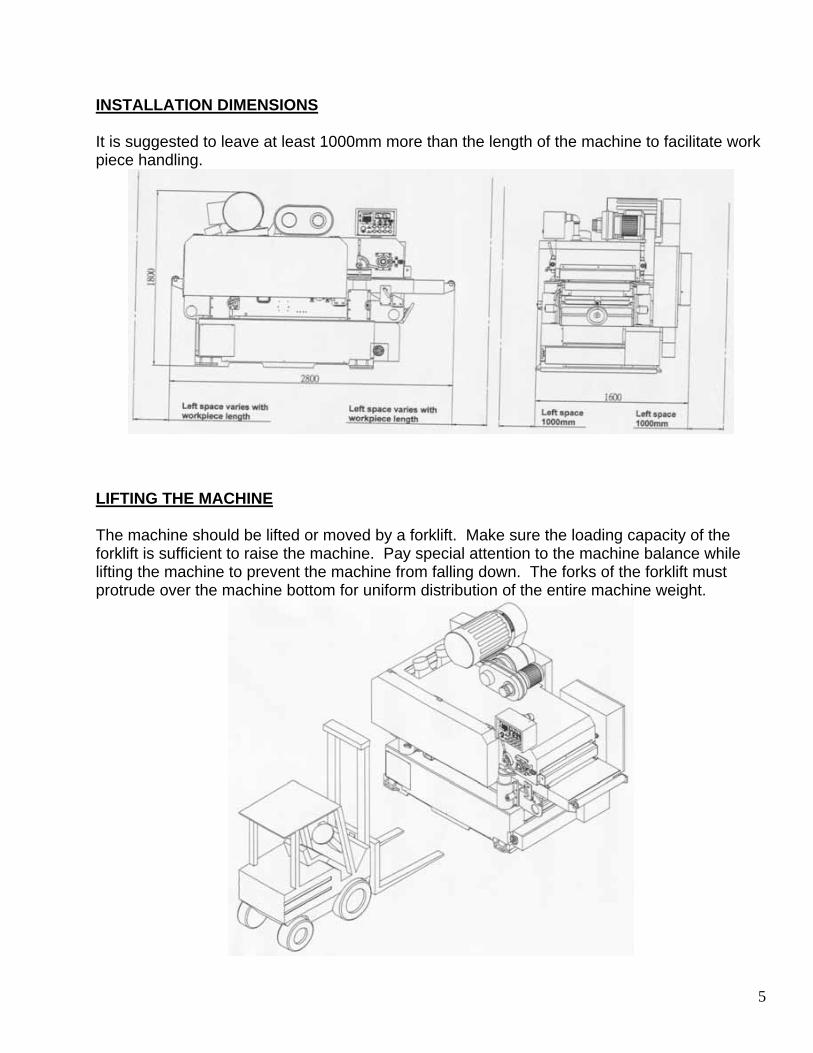
INSTALLATION DIMENSIONS It is suggested to leave at least 1000mm more than the length of the machine to facilitate work piece handling.
LIFTING THE MACHINE The machine should be lifted or moved by a forklift. Make sure the loading capacity of the forklift is sufficient to raise the machine. Pay special attention to the machine balance while lifting the machine to prevent the machine from falling down. The forks of the forklift must protrude over the machine bottom for uniform distribution of the entire machine weight.

6
INSTALLING THE MACHINE The machine does not need to be bolted into the concrete floor, but needs a solid and level concrete floor. Leave proper space around the machine for conveniently handling the materials to be planed. See the instruction on INSTALLATION DIMENSIONS. Four steel pads are furnished with the machine, which are to be placed under the leveling screws at the four corners under the machine base. Make leveling adjustments after the machine has been located at the work site.

7
CONNECTING POWER SOURCE WIRES The machine needs a three-phase, AC power source. After the power wires has been connected, check to see if the power wires are correctly connected to the correct connection points. NOTE: Do not start upper and lower cutterhead switch before making sure of the direction. Check method: press power source switch, press upper cutterhead with pressure mechanism elevation switch, check if the direction is correct. If it runs to the opposite direction, change the two outside wires for obtaining the correct running direction. Make electrical wiring as according to the Electrical Wiring Diagram. All electrical of electronic troubleshooting and repair should be undertaken only by personnel who are properly trained and have adequate knowledge and skill. Always close the electrical control panel door to prevent dust entering into it, as this may cause damage on the electric circuit. The output wires should be correct in sizes as rated, and avoid wetting.
Connect the Power Wires Power Supply 3 phase, 380V/50HZ. Customers specify
voltage. The setup environment is effective for EMI, but should be separate from other machines or facility. Keep the voltage variation in 10%.
Current Top spindle drive motor: 30HP The rated current is 42 A. Bottom spindle drive motor: 20HP The rated current is 27.3 A.
Setup Cable Rated Cross Section…6mm. Circuit Breaker According to the current to select its suitable
breaker, applying to the standards of IEC or VDE.

8
CONNECTING THE DUST COLLECTION SYSTEM Upper and right side of the machine is equipped with two dust collection hoods, which should be connected to the dust collector by using a flexible hose. The dust hood outlet is 6” (150mm) X 2, 5” (125mm) X 1 diameter. Do not operate this machine until the dust collector is running, which may prevent dust jam to affect the machine operation performance. NOTE: The length of flexible hose should not exceed 3 meters. Too long flexible hose may
affect the planing performance of the machine and quality of planing.

9
GENERAL SAFETY RULES There is a certain amount of hazard involved with the use of woodworking machine. Using the machine with the respect and caution demanded as far as safety precautions are concerned will considerably lessen the possibility of personal injury. However, if normal safety precautions are overlooked or ignored, severe personal injury to the operator can occur. 1. Read the operation manual before operating this machine. 2. If you are not thoroughly familiar with the machine operation, obtain advice from a
supervisor or other qualified person. 3. The machine should be disconnected from the power source before performing
maintenance or adjustments to the internal mechanisms, or when making repairs. 4. After maintenance job is finished, check to see if there are any tools or objects left on the
machine. Close all safety guards. 5. Before leaving the machine, make sure the work area is clean. 6. Check timber for loose knots, nails, or other items, which may cause a hazard or affect the
machine’s performance. 7. Learn the machine’s applications and limitations, as well as the specific potential hazads
peculiar to it. Keep the machine in top condition for best and safest performance. 8. Keep all guards in place and in working order. 9. Do not force the machine. It will do the job better and be safer working at the rate for which
it was designed. 10. All children and visitors should be kept a safe distance from the working area. 11. The operator should keep proper footing and balance at all times. 12. Do not operate the machine while under the influence of drugs, alcohol or any other
medication. 13. Avoid awkward operations and hand positions where a sudden slip could cause your hand
to move into the cutterhead. 14. Never leave the machine until it comes to a complete stop, and never leave the machine
running unattended. 15. The employer is responsible for selecting competent and qualified employees. 16. The employer must make sure that employees study and utilize this safety information. 17. Supervisors must alert personnel of any unsafe practices they observe. 18. All employees should be aware of first aid facilities and be encouraged to use them,
regardless of the severity of the injuries. 19. Fire prevention must be practiced and fire protection must be available to prevent loss of
life, personal injury, and property damage. 20. Safety shoes should be worn to provide protection against rolling objects, falling objects,
and sharp edges in the workplace. 21. Eye protection should be worn and such devices should be carefully selected, fitted and
used. Compulsory wearing of glasses with impact resistant lenses and side shields is a good safety policy. All eye protection should conform to ANSI 87 standards.
22. Wear hearing protection when operating the machine. 23. Do not wear rings necklaces or jewelry around moving machinery. 24. Do not wear loose fitting clothes. Clothing should be comfortable, but long sleeves,
neckties, etc. should not be worn. 25. Do not wear gloves or other hand covering articles around moving machinery. 26. Cover long hair with a hair net or cap.

10
27. Protective guards and shields must be in place at all times unless they must be removed for specific service or maintenance. They should be immediately replaced when service or maintenance is completed.
28. Make sure that operator clearly knows how to stop the machine before starting work. 29. Never clean or remove chips while the machine is running. 30. Maintain the machine in good operating condition. Report unusual conditions or machine
malfunctions immediately. 31. Do not alter or remove guards and warning labels. 32. Keep the immediate area clean. Do not allow the floor to become slippery, or covered with
dust or obstacles. Dust that accumulates in the work area is a hazard that can cause you to fall or slip against the machine or its controls.
33. Employees should be required to report to their supervisors any hazardous condition of the machine or in the immediate area.
ELECTRICAL SAFETY RULES 1. Do not alter or bypass any protective interlock. 2. Before starting the machine, read and observe all warning labels and markings such as
nameplates and identification plates. 3. Only personnel who are properly trained and have adequate knowledge and skill should
undertake all electrical/electronic troubleshooting and repair. 4. Use extra precautions in damp areas to prevent yourself from accidental grounding. 5. Make sure your body and your tools are clear of electrical grounding. 6. The control panel doors should be opened only when it is necessary to check the electrical
equipment or electrical wiring. 7. Before applying power to any equipment, establish without a doubt that all persons are
clear. 8. Be alert and be sure you can work with no outside distractions. 9. Avoid wearing metal frame glasses or wearing a metallic necklace or chain, and never work
on electrical equipment while wearing rings, watches, or bracelets. 10. When replacing conductors, make sure they conform to the manufacturer’s specifications,
including proper color-coding. 11. Do not alter the electrical circuits. If machine damage is caused by an unauthorized
alteration, the user is responsible, not the manufacturer. 12. Always assume the electrical power is ON and treat circuit as live. This caution develops a
habit that may prevent an accident. 13. Give capacitors time to discharge. Otherwise, it should be done manually with care. 14. Use proper test equipment to make certain you have an open circuit. Test equipment must
be checked and calibrated at regular intervals. 15. Open the control panel doors only when it is necessary to check the electrical equipment or
wiring. After closing the door, make sure the disconnecting means are operating with the disconnecting handle mechanism in its proper position.
16. All covers on junction boxes must be closed before leaving any job.

11
WARNING LABEL LOCATIONS

12
Warning Label 1 The “Hazardous voltage” label, shown in figure, is affixed to the electrical control box. The label warns service personnel to unplug the power supply before attempting any service work on this machine. Warning Label 2 The “Danger-Sharp Knife” label, shown in figure, is affixed to the upper and lower cutterhead. The label warns the operator and service personnel of the very sharp knives and to keep out of this area except for installing the knives. Warning Label 3 The “Warning-Feed work piece from this end” label, shown in figure, is affixed to the frame at infeed end. It alerts the operator that this is the infeed end of the machine. Warning Label 4 The “Danger-Do not put your hand inside” label, shown in figure, is affixed to the upper front of the infeed table. It alerts the operator not to put his hand inside the clamp seat, the back of feeding end. Warning Label 5 The “Safety Instructions” label, shown in figure, is attached to the front of the machine frame. The label provides convenient safeguard instructions for the operator and service personnel. Warning Label 6 The “Warning-Identification before pressure mechanism elevation” label, shown in figure, is affixed to the left of the electrical control panel. It alerts the operator to follow the steps to operate before pressure mechanism elevation, otherwise they cannot elevate.

13
SPECIFICATIONS Max. Width of Planing 650mmMax. Thickness of Planing 200mmMin. Length of Planing 385mmBottom Spindle Speed 5000RPM (50HZ), 6000RPM (60HZ)Top Spindle Speed 5000RPM (50HZ), 6000RPM (60HZ)Feed Speed (variable) 7.5M-30M (50HZ), 9M-36M (60HZ)Bottom Spindle Drive Motor 10HP-20HPTop Spindle Drive Motor 15HP-30HPFeed Drive Motor 5HPElevation Motor 1-1/2HPDust Hood Outlet Diameter 150mm (6”) x 2Table area (L x W) 1355 x 770mmTable Height from Floor 850mm (32-1/2”0Machine Dimensions (L x W x H) 2300 x 1650 x 1800mmPacking Dimensions (L x W x H) 2500 x 1850 x 2100mmNet Weight 3000 KGSGross Weight 3500 KGS

14
LEGEND OF TH MACHINE

15
ELECTRICAL CONTROL PANEL
1. Lower Cutterhead Motor Amp. Meter 1 2. Upper Cutterhead Stop Switch 3. Power Indication Lamp 4. Digital Controller 5. Feed Roller Start Switch 6. Feed Roller Stop Switch 7. Lower Cutterhead Start Switch 8. Lower Cutterhead Stop Switch 9. Upper Cutterhead Start Switch 10. Upper Cutterhead Stop Switch 11. Power Source Switch 12. Power Source Stop Switch 13. Interlock 14. Overload 15. Emergency Stop Switch

16
FUNCTION DESCIPTION FOR ELECTRICAL CONTROL PANEL
Switch Figure Switch Name Function 1.
Lower Cutterhead Motor Amp. Meter
It indicates percentage of planing load for lower cutterhead motor.
2.
Upper Cutterhead Motor Amp Meter
It indicates percentage of planing load for upper cutterhead motor.
3.
Power Indication Lamp When this lamplight is on the machine is then under power.
4.
Digital Controller Used for setting the thickness of plane.
5.
Feed Roller Start Switch Press this switch for starting feed rollers running. This switch is effective only after upper and lower cutterhead are started.
6.
Feed Roller Stop Switch When this switch is pressed, feed rollers stop.
7.
Lower Cutterhead Start Switch
Press this switch for starting lower cutterhead running.

17
Switch Figure Switch Name Function
8.
Lower Cutterhead Stop Switch
When this switch is pressed, the lower cutterhead and feed rollers stop.
9.
Upper Cutterhead Start Switch
Press this switch for starting upper cutterhead running.
10.
Upper Cutterhead Stop Switch
When this switch is pressed, the upper cutterhead and feed rollers stop.
11.
Power Source Switch When this switch is pressed, the machine is underpowered and ready for operation.
12.
Power Source Stop Switch When this switch is pressed, the machine is stopped for operation.
13.
Interlock This light means safety door is not closed
14.
Overload Motor overload
15.
Emergency Stop Switch During operation, if there is any abnormal motion occurring, press this switch for immediately stopping all motions of the machine.
18
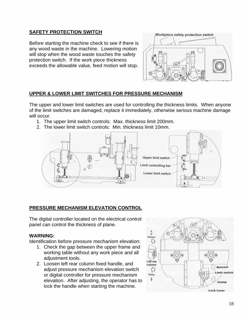
SAFETY PROTECTION SWITCH Before starting the machine check to see if there is any wood waste in the machine. Lowering motion will stop when the wood waste touches the safety protection switch. If the work piece thickness exceeds the allowable value, feed motion will stop. UPPER & LOWER LIMIT SWITCHES FOR PRESSURE MECHANISM The upper and lower limit switches are used for controlling the thickness limits. When anyone of the limit switches are damaged, replace it immediately, otherwise serious machine damage will occur.
1. The upper limit switch controls: Max. thickness limit 200mm. 2. The lower limit switch controls: Min. thickness limit 10mm.
PRESSURE MECHANISM ELEVATION CONTROL The digital controller located on the electrical control panel can control the thickness of plane. WARNING: Identification before pressure mechanism elevation:
1. Check the gap between the upper frame and working table without any work piece and all adjustment tools.
2. Loosen left rear column fixed handle, and adjust pressure mechanism elevation switch or digital controller for pressure mechanism elevation. After adjusting, the operator has to lock the handle when starting the machine.

19
ELECTRICAL SUPPLY CONNECTION
Type: 650DP SEECF: 230V/460V, 30HP, 25HP Electric Part List
Description Qty Type CNNE Specifications Item Power Light/R 1 110V 10mm Light/R/Y 1 110V 10mm Light Flat Head Push Button/G 4 1A 110V 22mm PB3,PB5,PB7,PB9 Flat Head Push Button/R 4 1B 22mm PB2,PB4,PB6,PB8 Lock Big Head Push Button/R 2 1B 22mm PB1,PB12 Magnetic 4 LC1D4011 4A1B 220V, 15HP 110V MS1,MS2,MS4,MS5 Magnetic 2 LC1D3801 4A1B 220V,12HP 110V MS3,MS6 Magnetic 1 LC1D1810 4A 220V, 5.5HP 110V MS7 Magnetic 2 LC1D0901 3A1B 220V, 3HP 110V MS8,9 Aided 1 LA1DN11 1A1b MS7 Overload 1 LR2D3357 40A-48A OL1 Overload 1 LR2D3355 30A-40A OL2 Overload 1 LR2D1322 12A-18A OL3 Overload 1 LR2D1310 4A-6A OL4 Wye Delta Timer/Air 2 2A2DT2 4A-6A 30S T1,T2 Relay 1 MY2 2A2B 5A, 240V 110V R1 CT 2 RCT35 5:200A Current Meter 2 YL80 5:200A Fuse 2 DF6AB10 4A,4A F1,F2 PT 1 330VA PT1 No Fuse Breaker 1 3P200A 3P 200A Limit 5 XCE118 1A1B LS1,LS2,LS4,LS5,LS7 Limit 1 TZ6102 1A1B LS3 Limit 1 TZ6001 1A1B LS6 Terminal Board 3 IN200K 3P 240A TB1 Terminal Board 20 IN13C 20A TB2,TB3

20
CURRENT CONSUMPTION FOR MAJOR ELECTRICAL PARTS
Description Qty Specifications Top Spindle Drive Motor 1 30HP 3PH
380V 50HZ 22KW 46A
Bottom Spindle Drive Motor 1 20HP 3PH 380V 50HZ 15KW 31A
Fed Drive Motor 1 5HP 3PH 380V 50HZ 3.7KW 9A
Lubricator 1 220V 80W INITIAL CLEANING & LUBRICATION The machine is coated with rust preventative oil before shipment. When the machine has been moved to the proper work site, wipe the oil from the machine using a soft cloth soaked in kerosene. Do not use gasoline, lacquer thinner, or any other volatile solvent, as these may damage the paint surface of the machine. IDENTIFICATION BEFORE OPERATION 1. Mount the planer knives into the upper and lower cutterheads. See instructions given in
“MOUNTING THE UPPER & LOWER PLANER KNIVES”. 2. Make sure all guards and lock screws are tightened securely. 3. Remove all adjustment tools from the machine. 4. Check if the cutterheads run to the correct direction. 5. Check if the air hoses are connected. 6. Start the machine idle running for about 10 minutes. According to the wood thickness,
properly set the thickness of plane for upper and lower cutterheads. 7. The length of work pieces to be planed should not be shorter than 385mm. Allowable
maximum thickness of work piece is 200mm. 8. Start planing at low feed speed, and then gradually increase feed speed until a proper feed
speed is decided. 9. Try to plane a work piece, and check if the sizes after plane complied with the settings on
the digital controller. Make adjustment if necessary. 10. Make sure the product sizes are correct before performing normal planing operations.

21
STARTING PROCEDURES FOR THE MACHINE 1. Press the power switch, and then the machine is underpowered and ready for operations. 2. Press the lower cutterhead start switch. The lower cutterhead drive motor provides two
speeds starting. Do not start the upper cutterhead running until the lower cutterhead reaches to its full speed.
3. Press the upper cutterhead start switch. The upper cutterhead drive motor provides two speeds starting. Make sure the upper cutterhead reaches to its full speed.
4. Press the feed roller start switch. METHODS TO STOP THE MACHINE If any accident occurs, use the following switches to stop the machine. Therefore it is very important to understand the functions of the switches as shown below: Stop the machine by the reverse procedures to those for starting the machine.
1. Feed Roller Stop Switch When this switch is pressed, the feed rollers stop immediately.
2. Upper Cutterhead Stop Switch When this switch is pressed, the upper cutterhead stops immediately.
3. Lower Cutterhead Stop Switch When this switch is pressed, the lower cutterhead stops immediately.
4. Power Source Stop Switch When this switch is pressed, the machine stops immediately.
Emergency Stop Switch
1. This emergency stop switch is pressed only under emergency conditions. If possible, press this switch until the work piece has moved out of the machine. Reverse the normal starting procedures to restart the machine, which may avoid work piece jamming against the planer knives or planer knife damage.
2. Do not press the emergency switch while in normal operation.

22
LUBRICATOR Form a habit to check this lubricator everyday for ensuring its normal function at all times. Otherwise, a lubrication failure may cause serious damage to the machine. When the lubricator is damaged, stop the machine operation immediately to prevent damage on the link chain conveyor due to lack of lubrication. The operation of this lubricator is simple. The proper settings of the “ON” and “OFF” positions can ensure the proper amount of oil for the feed chain. For adjustment of the amount of oil to be applied, set the “ON” position of the lubricator to the desired time of lubrication. Set the “OFF” position at the desired time of intervals between discharge of lubrication. Instruction for Manual Oil Feeding: 1. If continued lubricating is required, press “F” key, at the time, the indicator of act is light and
pumping oil out. 2. Press “F” key, it does not influence the time of interval. 3. Maximum pumping oil time: 4 min. 4. Prior to the first operation, press “F” key by hand in order to fill up the pipe with oil. Setting Time of Auto Oil Feeding: 1. Set the “ON” and “OFF” at the respective position for the selected discharge amount. 2. Set the position of time not over 0-60 or 0-180. 3. “OFF” time should be over than the triple of “ON” time. 4. Time value in +3%. 5. ACT indicator will light during the actuating-phase. 6. INT indicator will light during the intermittent-phase. When oil is lower than the minimum level, the ACT and INT lamps will glitter, the motor will stop, and the alarm will ring. At this time, refill with clean oil as needed. Recommended Lubrication Oil:
Type Viscosity Ambient Temp Shell Tonna 32 32 0°-5° Shell Tonna 68 68 5°-40° ISO VG32 32 0°-5° ISO VG68 68 5°-40° 1. Fill only with new oil. Do not use any reclaimed oil 2. Keep interior of oil box clean. 3. The lubricator is a critical part of the machine. A proper lubrication for the link chain
conveyor is an important factor for ensuring the accuracy of the machine. Make sure the lubricator works normally and lubrication at the bottom of link chain conveyor is proper.
4. In normal duty, setting the lubricator works once every 2 or 3 hours. And “NO” time should be 5 to 10 seconds. In heavy duty, setting the lubricator works more often.

23
Automatic Lubricator

24
Hand Oiler 1. Lubricate the left and right column system slide bushing and angle screw by hand oiler. 2. Lubricate at least once a week. 3. Do not over apply oil to save blockage. 4. Apply X-Oil for lubrication.
CONTROL PANEL OF DIGITAL CONTROLLER This control panel is mounted on the electrical control panel for controlling the height adjustment for the upper and lower cutterheads and pressure mechanism. The digital controller provides accurate control for thickness of plane. AUTOMATIC START OF DIGITAL CONTROLLER 1. For example, if current display is 100, and you need to have
a 200 display then set it as below procedures. 2. Press numeric keys (0-9) for entering 200. 3. Press START key for reaching 200 position. 4. During entering value or starting, if STOP key is pressed, the
controller will stop immediately and return to a stop condition.

25
Manual Thickness Setting 1. Setting the thickness of cut as according to the work piece
size. 2. Press numeric keys (0-9) for entering the correct value that
the upper and lower cutterhead will move. 3. Once the value is entered, the value display may flash. 4. Press SET key, after 5 seconds the LED will display the
entered value. At this time, the value display will stop flashing, meaning the value has been successfully entered.
5. After the first work piece has been cut, measure the work piece to see if the cut size is correct. If necessary, make value setting again until a correct thickness of cut is obtained.
SET UP UPPER CUTTERHEAD WITH PRESSURE MECHANISM HEIGHT Suppose the thickness of plane is 100mm, set the height of pressure mechanism as 100mm on the digital controller. If the size after plane becomes 97mm,which differs from the desired size, it needs to calibrate the sizes on the digital controller. Make size calibration as below procedures. First press the SET key, at this time the LED will display “0”. Press numeric keys 97, and keep pressing on the SET key 2-3 seconds. Enter numeric keys 100 into the controller. Press START key to accomplish the size calibration. THE WOOD THICKNESS FAST SETUP 1. Put in an identical wood block sample, which can be used as a
template. 2. To make the thickness setting limit switch down to touch the
sample for fast setup. ADJUST FEED ROLLER PRESSURE 1. The F.R.L. unit actuates the feed rollers. The suggestion
pressure is within 4-6 kg/cm². 2. The separate air cylinders control each pressure roller.

26
ADJUST THICKNESS OF PLANE FOR UPPER AND LOWER CUTTERHEAD 1. Perform thickness of plane adjustment should consider the
wood surface condition. 2. Adjust thickness of plane for the lower cutterhead:
A. Loosen the lock lever (1). Turn the elevation hand wheel (2) to the desired thickness of plane. The thickness adjustment amount is indicated on the scale (3).
B. Tighten the lock lever (1). 3. Adjust product thickness:
A. The product thickness after planing is adjusted by the digital controller (4) panel located on the electrical control panel. Thickness can be read on the scale (5).
B. The hand wheel (6) is used for micrometric adjustment.
4. The allowable maximum thickness of plane for the upper and lower cutterhead is 14mm.
5. Start cutting at low feed speed, and then gradually increase feed speed.
UPPER AND LOWER CUTTERHEAD LEVELING ADJUSTMENT 1. Leveling Adjustment for Upper Cutterhead:
A. Pulling down the dust guard below on the left elevation screw. Loosen the lock screw. Insert a stick into the adjustment hole. Turn the adjustment nut until proper leveling of the upper cutterhead is obtained.
B. Return all parts to their original condition after
adjustment. 2. Leveling Adjustment for Lower Cutterhead:
A. Loosen the 4 fix screws, and then turn the 4 leveling adjustment screws until the knife-edge is leveled with the read table surface.
B. If the knife-edge is higher than the rear table surface, a concave cut at the rear end of work piece will occur.
C. If the knife-edge is lower than the rear table surface, a concave cut at the front end of work piece will occur.
D. Refer to below figure. NOTE: In case uneven thickness of work piece after cut occurs, check if the 4 knives edges
located at the same level or not if so, make leveling adjustment for the 4 knives.
27
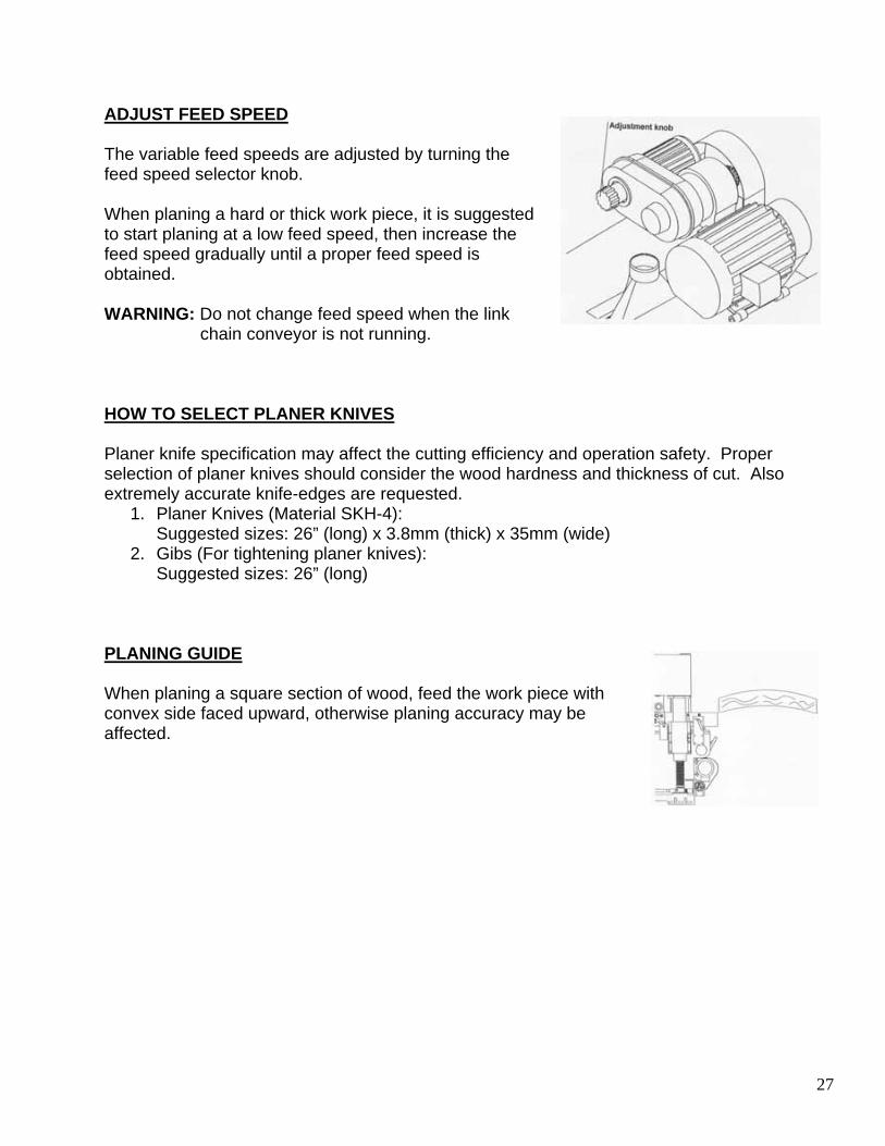
ADJUST FEED SPEED The variable feed speeds are adjusted by turning the feed speed selector knob. When planing a hard or thick work piece, it is suggested to start planing at a low feed speed, then increase the feed speed gradually until a proper feed speed is obtained. WARNING: Do not change feed speed when the link
chain conveyor is not running. HOW TO SELECT PLANER KNIVES Planer knife specification may affect the cutting efficiency and operation safety. Proper selection of planer knives should consider the wood hardness and thickness of cut. Also extremely accurate knife-edges are requested.
1. Planer Knives (Material SKH-4): Suggested sizes: 26” (long) x 3.8mm (thick) x 35mm (wide)
2. Gibs (For tightening planer knives): Suggested sizes: 26” (long)
PLANING GUIDE When planing a square section of wood, feed the work piece with convex side faced upward, otherwise planing accuracy may be affected.

28
REPLACING THE PLANER KNIVES WARNING: Turn power off before replacing the planer knives, and wait until the upper and
lower cutterheads come to a complete stop. The planer knives are extremely sharp. Pay special attention when replacing the planer knives to avoid injury.
1. Removing the Planer Knives: A. Loosen the two lock handles (1). Turn the fix spot
in counter-clockwise direction and then pull the cutterhead housing. Tighten the cutter fix screw (2).
B. Loosen the fix screw (3), remove in sequence the gibs (4), planer knives (5) and springs (6).
2. Mounting the Planer Knives: A. Mount in sequence the springs (6), planer knives
(5) and gibs (4) into the cutterhead. B. Press down the knives (5). Then place the knife
setting gauge (7) onto the cutterhead. C. Make sure the inside diameter (5) of knife setting
gauge (7) properly. Contacted with knife-edge. To adjust the cutter by screw (9).
D. Tighten the gibs (4) securely, and make sure the knives (5) and gibs (4) are located at the correct direction. Take out the knife setting gauge (7), loosen the cutterhead fix screw (2).
E. Push the cutterhead housing to its position. Then tighten the lock handles (1). In clockwise direction fix the cutterhead housing.
NOTE: While pushing the cutterhead housing to its position, check if the shaft coupler (8) is engaged.
SAFETY RULES FOR MAINTENANCE This machine has been factory inspected and tested before shipment that will ensure the dependable performance for years of operation. However, it is very important to perform periodical maintenance and cleaning. If there is any part that becomes worn out or damaged, immediately repair or replace the abnormal parts which may prevent damage on the other mechanism of the machine or danger to the operator. WARNING:
1. Unplug the electrical power before making maintenance. 2. Pay special attention when replacing the saw blade.

29
ADJUST FEED ROLLER HEIGHT AND LEVELING 1. Adjust Upper Feed Roller Height and Leveling:
A. Adjust upper feed roller position by turning the screws located under the roller brackets.
B. See figure below for correct feed roller position. 2. Adjust Lower Feed Roller Height and Leveling:
A. Adjust lower feed roller position by turning the screws located under the flange bearings.
B. See figure below for correct feed roller position. WARNING: Make sure the power is turned off the upper and lower cutterhead comes to a
complete stop before making adjustments. A qualified technician should make adjustments.
ADJUST V-BELT TENSION FOR UPPER CUTTERHEAD After the machine has been operated for a long time, the cutterhead v-belt may be loosened gradually. At this time, it needs to adjust the v-belt tension. 1. Turn off the power source before adjusting the v-belt
tension, and wait until the upper cutterhead and lower cutterhead come to a complete stop.
2. Turn the v-belt tension adjustment screws for the upper cutterhead until a proper tension is obtained. Then tighten the fix nuts.
3. Check the upper cutterhead v-belt tension once a week.

30
ADJUST V-BELT FOR LOWER CUTTERHEAD 1. Turn off the power source before adjusting the v-belt
tension, and wait until the upper and lower cutterhead come to a complete stop.
2. Turn the v-belt tension adjustment screws for lower cutterhead until a proper tension is obtained. Then tighten the fix nuts.
3. Check the lower cutterhead v-belt tension once a week. ADJUST TRANSMISSION CHAIN TENSION 1. Turn off the power source before adjusting the
transmission chain tension, and wait until the upper and lower cutterhead come to a complete stop.
2. Remove the guard cover. 3. Loosen the 4 fix nuts located under the gear reducer.
Turn the 4 chain tension adjustment nuts until a proper tension is obtained. Tighten the fix nuts after transmission chain tension has been properly adjusted.
4. Fix the guard cover to its position and tighten it securely.
5. Check the transmission chain tension once a month. ADJUST V-BELT TENSION FOR ELEVATION DRIVE MOTOR 1. Turn off the power source before adjusting the v-belt
tension, and wait until the upper and lower cutterhead come to a complete stop.
2. Remove the guard cover. 3. Turn the v-belt tension adjustment screw proper tension is
obtained. Tighten the screws after the v-belt tension has been properly adjusted.
4. Fit the guard cover to its position and tighten it securely. 5. Check the v-belt tension once a month.

31
ADJUST HOLD DOWN PRESSURE FOR SPIKE CONVEYOR The hold down pressure for spike conveyor can be adjusted by setting the position of the adjustment handle. For normal hold down pressure the adjustment handle is set at the highest position in the groove. If the wood thickness is varied, set the adjustment lever at a lower position in the groove. This may increase feeding capability. Loosen the adjustable-handle lock lever before operating the adjustment handle. Tighten it securely after pressure is adjusted. ADJUST TENSION OF SPIKE CONVEYOR After the machine has been operated for a long period of time the spike conveyor tension may have become loosened. This may result in poor feeding of work piece. If this happens the spike conveyor tension needs to be adjusted. Loosen the nut and turn nut clockwise to tighten the tension of spike conveyor. Tighten the nut securely after spoke conveyor tension has been properly adjusted. Turning the tension adjustment nut clockwise to tighten the tension of spikes conveyor. ADJUST GEAR BOX CHAIN TENSION 1. Turn off the power source before adjusting the gear
box chain tension, and wait until the upper and lower cutterhead and feeding rollers come to a complete stop.
2. Remove the guard cover. 3. Loosen the 2 fix screws and turn the chain tension
adjustment screws until a proper tension is obtained. Tighten the fix screw after gearbox chain tension has been properly adjusted.
4. Fix the guard cover to its position and tighten it securely.
5. Check the gearbox chain tension once a month.

32
LUBRICATION LOCATIONS
LUBRICATION INSTRUCTIONS
Parts Lubrication Location Lubricants Frequency 1. Hand Oiler 1 SHELL slide oil T68
(Sliway Tonna 68) Lubricate once a week
2. Automatic Lubricator
1 SHELL slide oil T68 (Sliway Tonna 68)
Fill oil when alarm sounds
3. Flanged Bearing UCFL-205
1 SHELL grease R2 (Grease Alvania R2)
Grease once a month
4. Upper and lower cutterhead housing
1,2 SHELL grease R2 (Grease Alvania R2)
Grease once a month
5. Universal joint 12 sets
1,2 SHELL grease R2 (Grease Alvania R2)
Grease once a month
6. Cutterhead rear bracket. (One each for upper and lower cutterhead)
1 SHELL grease R2 (Grease Alvania R2)
Grease once a month
7. F.R.L. unit 1 SHELL slide oil T68 (Sliway Tonna 68)
Lubricate once a week
8. Oil cup 1 SHELL slide oil T68 (Sliway Tonna 68)
Lubricate once a week
9. Four grease nipples
1,2,3,4 SHELL grease R2 (Grease Alvania R2)
Grease once a week

33
ELECTRICAL SUPPLY CONNECTION

34

35
ORDERING THE REPLACEMENT PARTS All parts listed may be ordered directly from your local distributor or the manufacturer of the machine. When ordering the replacement parts, always give the following information:
1. Date of manufacturing 2. Machine model number 3. Parts number 4. Parts description 5. Required quantities

36
A: BASE ASSEMBLY

37
A: Base Assembly
No Part Description Qty Part No 1 Base 1 111-650DP 2 Elevation System 1 E 3 Differential Speed Unit 2 MBO2 4 Shaft Coupler 2 149-650D 5 Connection Shaft 1 151-650D 6 Differential Speed Unit Pulley 1 116-650D 7 Elevation Motor Base 1 109-650D 8 Elevation Drive Motor 1 MC2HP 9 Elevation Drive Motor Pulley 1 114-650D 10 Fort Cover 1 C13-650D 11 Lower Course Roller Fix Plate 1 C08-650D 12 Lower Cutterhead Pulley Guard 1 246-650D 13 Lower Cutterhead Dust Hood 1 C09-650D 14 Lower Cutterhead Motor 1 MEAC2P 15 Lower Cutterhead Pulley 1 052B-650D 16 Lower Cutterhead Housing Assembly 1 A2 17 Lower Cutterhead Motor Base 1 C27-650DP 18 Lower Cutterhead 1 105-650D 19 Front Slide Guard 1 C03-650DP 20 Elevation Belt Guard 1 C02-650D 21 Cover 1 C04-650D 22 Connection Shaft Cover 1 C01-650D 23 Slide Guard 1 C07-650DP 24 Slide Guard 1 C06-650DP 25 Right Front Slide 2 1004-650DP 26 Left Front Slide 2 1003-650DP 27 Base of Saw Brake 1 052-1-650DP

38
A1: FRONT TABLE ASSEMBLY
A1: Front Table Assembly
No Part Description Qty Part No 1 Front Table Lip 1 112-650DD 2 Plate 1 110-650DP 3 Nut Holder 1 108-650D 4 Bushing 1 118-650D 5 Table Adjustment Rod 1 119-650DP 6 Hand Wheel 1 065-1-365 7 Hand Wheel Washer 1 120-650D 8 Fence 1 174-650DP 9 Fence 1 174-1-650DP
10 Roller Base (Left) 1 094-650D 11 Roller Base (Right) 1 093-650D 12 Bearing 6206 2 6206 13 Front Roller 1 096-650D 14 C Circlip S-30 2 SCS30 15 Roller Spindle 1 095-650D 16 Retaining Ring External S-16 2 SCS16 17 Flanged Bearing UCFL-205 2 UCFL-205 18 Plate 1 103-650DP

39
A2: LOWER CUTTERHEAD HOUSING ASSEMBLY
A2: Lower Cutterhead Housing Assembly
No Part Description Qty Part No 1 Bearing 6200 2 B6200 2 Lower Cutterhead Slide Rod 2 053 3 Lower Cutterhead Housing Bracket 1 059 4 Lower Cutterhead Housing Bracket 1 058 5 Hexagonal Socket Head Screw M12-50 1 SC1250 6 Washer 12mm 1 SW12 7 Brass Ring 1 183-3 8 Pressure Plate 1 055-2 9 Rocker Handle 1 055-4
10 Pressure Bracket 1 183-2 11 Stopper 1 054-1 12 Lower Cutterhead Housing 1 055 13 Nut M12 1 SN12 14 Lower Cutterhead Chip Guard 1 C11 15 Pressure Plate 3 183-1 16 Shaft Coupler 1 045 17 Bearing 6009 3 B6009 18 Clutch Housing 1 049 19 Bearing Lock Nut AN-09 2 AN09 20 Pulley Shaft 1 046 21 Lower Cutterhead Pulley 1 51 22 SAW45 2 Teeth Washer 23 Bearing Inner Spacer 1 047 24 Lower Cutterhead Guard 1 C12

40
A3: LOWER CUTTERHEAD ASSEMBLY

41
A3: Lower Cutterhead Assembly
No Part Description Qty Part No 1 Cutterhead Pulling Handle 1 184 2 Fixed Stock 1 055-3 3 Cutterhead Housing 1 054D 4 Turn Handle 1 259 5 Bearing Cap 1 036 6 Spring 1 015A 7 Hexagonal Socket Head Screw M8-30 1 SC830 8 Teeth Washer AW-35 1 SAW35 9 Nut AN-06 1 AN-06 10 Bearing 6307 1 6307 11 Bearing Cap 1 041 12 O Ring #P40 1 #P40 13 Lower Cutterhead 1 040 14 Spring M6-16 1 M6X16 15 Spring 1 040-5 16 Planer Knife 1 040-4 17 Gib 1 040-1 18 Gib Lock Screw 1 040-2 19 O Ring #P50 1 P50 20 Bearing Cap 1 039 21 Bearing 6009 2 6009 22 Bearing Spacer 1 047 23 Bearing Cap 1 044 24 Shaft Coupler 1 045-1 25 Teeth Washer AW-09 1 SAW45 26 Nut AN-09 1 AN-09 27 Shaft Coupler Washer 2 AW09 28 Bearing 6200 1 6200 29 Lower Cutterhead Housing Bracket 2 069 30 Cutterhead Slide 1 053 31 Lower Cutterhead Housing Bracket 2 070

42
A4: REAR TABLE ASSEMBLY
A4: Rear Table Assembly
No Part Description Qty Part No 1 Rear Table 1 079DP 2 Rear Table Lip 1 113-650D 3 Rear Fence (Right) 1 175-650DP 4 Rear Fence (Left) 1 175-1-650DP 5 Flanged Bearing UCFL-205 2 UCRL-205 6 Collar 6 247-650D 7 Rear Lower Smooth Roller 1 133-650D 8 Roller Positioner 6 080 9 Roller Spindle 1 095-650D 10 C Circlip S-30 2 SCS30 11 Front Roller 1 096-650D 12 Bearing 6206 2 6206 13 Roller Base (Left) 1 093-650D 14 Roller Base (Right) 1 094-650D 15 Rear Lower Smooth Roller 2 133-650DP 16 Flanged Bearing UCFL-206 4 UCFL-206 17 Washer 2 199-650D 18 Universal Joint 2 161S-650D

43
B: UPPER MECHANISM ASSEMBLY

44
B: Upper Mechanism Assembly
No Part Description Qty Part No 1 Upper Cover 1 3001-650DP 2 Spike Conveyor 1 B7 3 Link Chain Conveyor 1 D 4 Flanged Bearing UCT210 2 UCF-210 5 Flanged Bearing UCT208 2 UCT-208 6 Adjustment Base 1 3006-650DP 7 Bracket 2 3002-650DP 8 Slide 4 3003-650DP 9 Upper Smooth Roller Assembly (Small) 1 B5 10 Upper Cutterhead Housing Assembly 1 B1 11 Upper Coarse Roller Assembly 1 B4 12 Upper Smooth Roller Assembly 1 B3 13 Air Cylinder 2 CY01-1 14 Eccentric Shaft Holder 3 3008-650DP 15 Eccentric Shaft Holder 1 3007-650DP 16 Upper Cutterhead Drive Motor 1 MEA 17 Upper Shaft Pulley 1 052B-650D 18 Adjustment Screw 2 3005-650DP 19 Nut 2 SN20 20 UCT Bearing Cover 1 3021-650DP 21 Gear Box Assembly 1 C 22 Gear 1 3009-650DP 23 Nut 1 AN-10 24 Teeth Washer 1 AW-10 25 Torque Limiter 1 KLG 26 Gear Box Base 1 3014-650DP 27 Speed Reducing Motor 1 MEAD4P06 28 Gear Reducer Dust Guard 1 C23-650DP 29 Upper Cutterhead Belt Guard 1 C19-650DP 30 Cover 2 C21-650DP 31 Front Anti-Kickback Finger Assembly 1 B6 32 Slide Cover 1 C15-650DP 33 Guard 1 C17-650DP 34 Rocker Handle 1 3020-650DP 35 Handle 1 HTRT1250 36 Roller Bracket 2 241-650D 37 Spring 2 3022-650DP 38 Arbor Flange 1 175-365 39 Arbor Flange 1 176-365 40 Control Box 1 650DPPF 41 Fixed Stock 1 3023-650DP 42 Gear Box Bracket 1 3025-650DP 43 Gear Box Bracket 1 3015-650DP

45
B1: UPPER CUTTERHEAD HOUSING ASSEMBLY

46
B1: Upper Cutterhead Housing Assembly
No Part Description Qty Part No 1 Bearing 6200 2 B6200 2 Cutterhead Slide 2 053A 3 Lower Cutterhead Housing Bracket 1 183-6 4 Lower Cutterhead Housing Bracket 1 183-7 5 Hexagonal Cutterhead Housing Screw M12-50 1 SC1250 6 Washer 12mm 1 SW12 7 Brass Ring 1 183-3 8 Pressure Plate 1 183-4 9 Nut M12 1 SN12 10 Rocker Handle 1 183-8 11 Pressure Bracket 1 183-2 12 Stopper 1 054-1 13 Lower Cutterhead Housing 1 183B 14 Front Movable Piece Spring 17 178 15 Front Stock Pressing Pad 17 181 16 Movable Piece Guide 1 180 17 Front Movable Piece Fix Shaft 1 177 18 Rear Stock Pressing Pad 13 182-A 19 Rear Movable Piece Spring 13 130 20 Hexagonal Socket Head Screw M6x10 1 SC6X10 21 Setting Block 1 183-1 22 Adjusting Block 1 183-11 23 Fixed Block 1 182-1 24 Pulley Shaft 1 046 25 Shaft Coupler 1 045 26 Bearing 6009 3 B6009 27 Upper Cutterhead Stopper 1 048 28 Upper Cutterhead Shaft Pulley 1 051A 29 Bearing Inner Spacer 1 047 30 Teeth Washer AW-09 2 SAW09 31 Bearing Lock Nut AN-09 2 SAN09 32 Pulley Washer 1 050 33 Upper Cutterhead Dust Hood 1 C20

47
B2: LOWER CUTTERHEAD ASSEMBLY

48
B2: Lower Cutterhead Assembly
No Part Description Qty Part No 1 Cutterhead Pulling Handle 1 184 2 Fixed Stock 1 183-5 3 Cutterhead Housing 1 054U 4 Turn Handle 1 259 5 Bearing Cap 1 36 6 Spring 1 036-1 7 Hexagonal Socket Head Screw M8-30 1 SC830 8 Teeth Washer AW-07 1 SAW07 9 Nut AN-07 1 SAN07 10 Bearing 6307 1 B6307 11 Bearing Cap 1 41 12 O Ring #P-40 1 GOP40 13 Upper Cutterhead 1 176 14 Spring M8-20 12 SFM820 15 Spring 12 040-5 16 Planer Knife 4 040-4 17 Gib 4 040-1 18 Gib Lock Screw 44 040-2 19 O Ring #P-50 1 GOP50 20 Bearing Cap 1 39 21 Bearing 6009 2 B6009 22 Bearing Spacer 1 47 23 Bearing Cap 1 44 24 Shaft Coupler 1 045-1 25 Teeth Washer AW-09 1 SAW09 26 Nut AN-09 1 SAN09 27 Cutterhead Slide 2 53 28 Upper Cutterhead Stopper 1 66 29 Bearing 6200 2 B6200 30 Upper Cutterhead Stopper 1 67 31 Shaft Coupler Washer 1 045-2

49
B3: UPPER SMOOTH ROLLER ASSEMBLY
B3: Upper Smooth Roller Assembly No Part Description Qty Part No 1 Coarse Roller Shaft 1 186-650D 2 Roller Rocker Arm 1 158-650D 3 Roller Rocker Arm 1 167-650D 4 Rocker Arm Collar 1 022-650D 5 Rocker Arm Guard 1 031-650D 6 Washer 2 199-650D 7 Bearing 6206 2 6206 8 Rocker Arm Collar 1 027-650D 9 Universal Joint 30 1 161S-650D 10 Dry Bearing 2520 2 DU2520 11 Rocker Arm Spindle 1 165-650D 12 Retaining Ring External C-25 2 SCS25

50
B4: UPPER COARSE ROLLER ASSEMBLY
B4: Upper Coarse Roller Assembly No Part Description Qty Part No 1 Upper Pressure Roller 1 171-1-650D 2 Roller Rocker Arm 1 158-650D 3 Roller Rocker Arm 1 167-650D 4 Rocker Arm Collar 1 022-650D 5 Rocker Arm Guard 2 031-650D 6 Washer 2 199-650D 7 Bearing 6206 1 6206 8 Rocker Arm Collar 1 027-650D 9 Universal Joint 30 2 161S-650D 10 Dry Bearing 2520 1 DU2520 11 Rocker Arm Spindle 2 165-650D 12 Retaining Ring External E-25 1 SCS25

51
B5: UPPER SMOOTH ROLLER ASSEMBLY (SMALL)
B5: Upper Smooth Roller Assembly (Small)
No Part Description Qty Part No 1 Upper Pressure Roller (Small) 1 3011-650DP 2 Bearing 6905 2 6905 3 Roller Spindle 1 3012-650DP 4 Roller Rocker Arm 2 3013-650DP 5 C Circlip S-25 2 SCS25 6 Roller Spindle 1 3010-650DP 7 Roller Spindle 2 3027-650DP

52
B6: FRONT ANTI-KICKBACK FINGER ASSEMBLY
B6: Front Anti-Kickback Finger Assembly
No Part Description Qty Part No 1 Base 1 3017-650DP 2 Anti-Kickback Finger (Long) 2 096-320 3 Fix Shaft 1 3018-650DP 4 Stop Collar 2 073-320 5 Washer 1 SW2028

53
B7: SPIKE CONVEYOR
B7: Spike Conveyor
No Part Description Qty Part No 1 Spike Conveyor Upper Bracket 1 3301-650DP 2 Rear Eccentric Shaft 1 3303-650DP 3 Front Eccentric Shaft 1 3304-650DP 4 Spike Conveyor Upper Bracket 1 3302-650DP 5 Base 4 3305-650DP 6 Screw 2 3308-650DP 7 Nut 2 SN12 8 Spike Conveyor Guide Chute 1 3306-650DP 9 Front Rock Arm Arbor 2 112-320 10 Stop Collar 8 3307-650DP

54
C: GEAR BOX ASSEMBLY
C: Gear Box Assembly
No Part Description Qty Part No 1 Gear Box 1 3101-650DP 2 Gear Set Assembly 2 C1 3 Gear Set Assembly 2 C2 4 Gear Set Assembly 1 C3 5 Spike Chain Wheel 1 3109-650DP 6 Bearing 6007 2 6007 7 Spacer 1 3110-650DP 8 Gear Set Assembly 1 C4 9 Gear Shaft Cover 1 210-650D 10 Washer 1 2210-320H 11 Gear Box Cover 1 C18-650DP

55
C1: GEAR SET ASSEMBLY
C1: Gear Set Assembly
No Part Description Qty Part No 1 Spur Gear 1 3102-650DP 2 Chain Wheel Shaft 1 3103-650DP 3 Collar 1 160-650DP 4 Bearing 6206 2 6206 5 Washer 2 199-650D 6 Gear Shaft Cover 1 210-650D 7 Universal Joint 25 1 161H-650D

56
C2: GEAR SET ASSEMBLY
C2: Gear Set Assembly
No Part Description Qty Part No 1 Spur Gear 1 3104-650DP 2 Chain Wheel Shaft 1 3103-650DP 3 Collar 1 190-650D 4 Bearing 6206 2 6206 5 Washer 2 199-650D 6 Gear Shaft Cover 1 210-650D 7 Universal Joint 25 1 161H-650D

57
C3: GEAR SET ASSEMBLY
C3: Gear Set Assembly
No Part Description Qty Part No 1 Spur Gear 1 3104-650DP 2 Idle Wheel 1 3105-650DP 3 Bearing 6206 1 6206 4 Washer 2 199-650D 5 Gear Shaft Cover 2 210-650D

58
C4: GEAR SET ASSEMBLY
C4: Gear Set Assembly
No Part Description Qty Part No 1 Idle Gear 1 3107-650DP 2 Idle Wheel Shaft 1 3106-650DP 3 Bearing 6006 1 6006 4 Washer 1 199-650D 5 C Circlip S-55 1 SCS55 6 Hexagonal Socket Head Screw M8x12 1 SC820 7 Idle Wheel 1 3108-650DP

59
D: LINK CHAIN CONVEYOR ASSEMBLY
D: Link Chain Conveyor Assembly
No Part Description Qty Part No 1 Driven Shaft 1 3202-650DP 2 Spike Chain Wheel 2 3203-650DP 3 Brake Shaft 1 3201-650DP 4 Spike Chain Wheel 2 3204-650DP 5 Pressure Spikes (1) 9 D1 6 Pressure Spikes (2) 9 D2 7 C Circlip S-50 2 SCS50 8 C Circlip S-40 2 SCS40

60
D1: PRESSURE SPIKES
D1: Pressure Spikes
No Part Description Qty Part No 1 Spike Conveyor Chain 1 RF2100-R 2 Pin Fix Plate 1 3206-650DP 3 Bush 4 3209-650DP 4 Bush 2 3210-650DP 5 Bush 1 3205-650DP 6 Feed Pin 24 3211-650DP 7 Spike Conveyor Chain 1 RF2100 8 Hexagonal Socket Head Screw M8x65 6 SC865 9 Nut M8 6 SN8 10 Spring 24 3212-650DP

61
D2: PRESSURE SPIKES
D2: Pressure Spikes
No Parts Description Qty Part No 1 Spike Conveyor Chain 1 RF2100-R 2 Pin Fix Plate 1 3208-650DP 3 Bush 4 3209-650DP 4 Bush 2 3210-650DP 5 Bush 1 3207-650DP 6 Feed Pin 25 3211-650DP 7 Spike Conveyor Chain 1 RF2100A 8 Hexagonal Socket Head Screw M8x65 6 SC865 9 Nut M8 6 SN8 10 Spring 25 3212-650DP
62
D3: ELEVATION SCREW ASSEMBLY
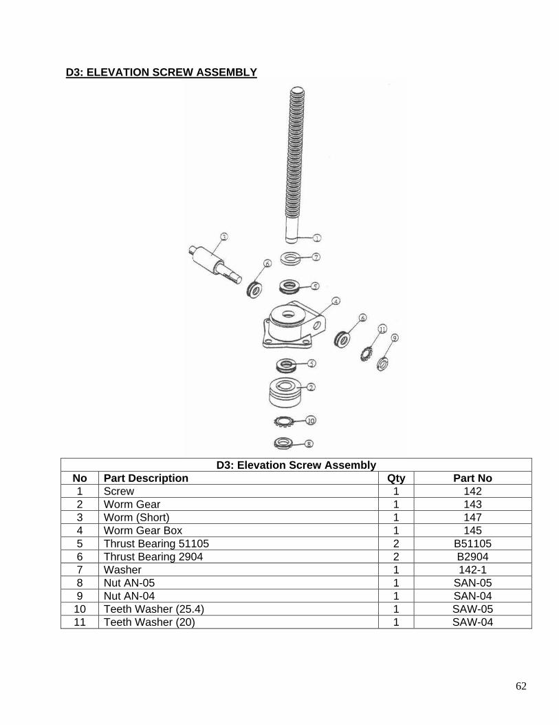
D3: Elevation Screw Assembly
No Part Description Qty Part No 1 Screw 1 142 2 Worm Gear 1 143 3 Worm (Short) 1 147 4 Worm Gear Box 1 145 5 Thrust Bearing 51105 2 B51105 6 Thrust Bearing 2904 2 B2904 7 Washer 1 142-1 8 Nut AN-05 1 SAN-05 9 Nut AN-04 1 SAN-04 10 Teeth Washer (25.4) 1 SAW-05 11 Teeth Washer (20) 1 SAW-04

63
D4: ELEVATION SCREW ASSSEMBLY (ENCODER)
D4: Elevation Screw Assembly (Encoder)
No Part Description Qty Part No 1 Screw 1 142 2 Worm Gear 1 143 3 Worm (Long) 1 147-2 4 Worm Gear Box 1 145 5 Thrust Bearing 51105 2 B51105 6 Thrust Bearing 2904 2 B2904 7 Washer 1 142-1 8 Nut AN-05 1 SAN-05 9 Nut AN-04 1 SAN-04 10 Teeth Washer (25.4) 1 SAW-05 11 Teeth Washer (20) 1 SAW-04

64
E: ELEVATION SYSTEM

65
E: Elevation System
No Part Description Qty Part No 1 Upper Mechanism Elevation 4 134-650D 2 Slide Bushing 2 135-650D 3 O Ring #125 8 GOP125 4 Handle 1 HTRT100M16 5 Nut M16 1 SN16 6 Limit Controlling Roller 1 257-650D 7 Limit Base 1 258-650D 8 Height Scale 1 C14-650D 9 Nut 4 141-650D 10 Elevation Nut 4 132-650D 11 Elevation Screw Assembly 1 E-2 12 Slide Bushing 2 137-650D 13 Elevation Screw Assembly 3 E-1 14 Shaft Coupler 6 148-650D 15 Connection Rod 2 150-650DP 16 Encoder Bracket 1 C25-650D 17 Encoder 1 ECD 18 Limit Controlling Bar 1 269-650D 19 Slide Bushing Positions 2 136-650D 20 Slide Bushing Positions 1 139-650D 21 Slide Bushing Positions 1 140-650D 22 Elevation Screw Assembly 1 256-650D