mvwg report to ms - wecc
TRANSCRIPT

MVWG Report to MS
Song Wang, MVWG ChairNovember 30, 2017

Recent Meetings
Meeting / Workshop Date
LMTF Meeting October 3, 2017
REMTF Meeting October 4, 2017
PPMVDTF Meeting October 4, 2017
MVWG Meeting October 4 ‐ 5, 2017

MVWG Activities Overview and Approval Items
• Load Modeling• Renewable Energy Modeling• System Model Validation• Generator Modeling, Testing, and Model Validation• HVDC Modeling• RAS and Relay Modeling• WECC Approved Dynamic Model List

Load Modeling

Present Load Model Development Status
• WECC TSS approved CMPLDW phase 2 at May 2017 meeting and it will be implemented in the WECC 2018 base case compilation schedule.
• WECC LMTF will continue to explore improvements to three‐phase and single‐phase motor models.
• WECC LMTF will focus on Load Composition• WECC LMTF will continue to working on the CMPLDW2 model
development.• MVWG will work on CMPLDW + DER_A model approval

Next Steps in Load Model
• Experience with CMPLD model provides a useful feedback on future improvements needed to make models behave better in gird simulations
• Increasing percentage of electronically connected loads(VFDs, ECMs, chargers)
• Distributed energy resources (PV solar, batteries) and changing characteristics from IEEE 1547 legacy to “smart” features
• Current composite load model CMPLD is rigid with respect to model components and their models
• Need for flexible load model structure

2nd Generation CMPLD
• Modular model structure– Need for model flexibility with respect to model components– Consistent rules for model data interpretation– Efficient data management – no need to repeat the same data many
times
• End‐Use component models– Distributed energy resources– Single‐phase motor models
• Performance model: Revise “stall” and “reaccelerate” characteristics• MOTORC model: validate MOTORC model, include in load component library

2nd Generation CMPLD
• …End‐Use Component Models– Power Electronic Load: We may need to differentiate between ECMs,
motor drives and electronic/computing/charging loads– Protection and Control Modules: Revise protection and control models
to allow for progressive motor tripping
• Model Benchmarking Studies– Develop a set‐up for model benchmarking, certify version releases

2nd Generation CMPLD ‐ Data
• Load Composition– Planners need to develop understanding of load composition in typical
commercial and residential buildings– Understand changes in load composition– Building surveys– Development and validation of next generation Load Composition
Model– Development of default data sets
• Data Management Tools– Load Model Data Tool for data management need to be aligned with
the new model structure– More transparent load composition data

Load Composition
• DOE project: to improve the load composition model– Load protection aggregation is one of the big challenge
• Surveys from the BPA Headquarter building– 80% of total load in the building are electronically connected (VFD
drive)
• Portable Power System Monitor technology applied for building monitoring

CMPLDWG model
• There is request to have distributed energy resources modeled in the WECC base case
• Based on current CMPLDWG (CMPLDW + PVD1) model, MVWG decided to develop DER_A model to represent distributed energy resources, and also replace PVD1 model in COMPLDWG model
• DER_A model has been tested and some observed inconsistencies in the response to voltage and frequency disturbance play‐in values displayed across the four software platform
• The new beta version will be created and re‐tested

CMPLDW Studies and Criteria

CMPLDW Studies and Criteria
Stalling of single-phase A/C disabled
Stalling of single-phase A/C enabled

Renewable Energy Modeling

DER_A Model development
• PVD1• PVD2• DER_A
• Siemens PTI ‐ Completed beta ready to test • GE – completed beta ready to test • PowerWorld – completed beta model• Beta version tested• New beta model ready for further test

Low Short‐Circuit Ratio System Generator/Convertor Model (REGC_B)
• Current source model (REGC_A)

Low Short‐Circuit Ratio System Generator/Convertor Model (REGC_B)
• Four more parameters (Re, Xe, Ted, Teq)

Weak Grid Option Modeling – REEC_D
• Wind power penetration increased• More weak grid interconnected projects• Weak grid projects experienced voltage oscillations and
turbine tripped• Weak Grid Option was applied in projects to help stabilizing
turbine• REMTF agreed to write a specification for additional module,
called REEC_D

Simulate Inverter Momentary Cessation
• Momentary cessation modeling requirement– Active and reactive currents
– Time delay
– Ramp rate limit of active current during recovery
– Reactive current control during recovery
– Priority between active and reactive current during recovery
• Generic models with MC modeling capability– Reec_a model
• Use reec_a for all wind/solar generators• Use In‐run epcl to simulate Momentary Cessation• Dynamic model errors
– Add to dynamic data checking list

Synthetic Inertial Response for wind
• General Remarks– WTGs can provide it without maintaining any reserve
– Typically, 5‐10% of rated power
– There is a minimum wind power output below which this response cannot be provided (typically 20 – 25% of rated)
– After initial burst of electrical energy, eventually energy has to be given back to reaccelerate the
– At or above rated wind speed there is little to no energy that has to be given back to reaccelerate turbine – can get the additional energy out of above rated wind energy
• Some Implementation Issues– The piece‐wise linear approximation may not exactly match all vendor implementations
– Will need 2D (or3D) look‐up table – Power versus Turbine Speed versus Wind Speed
– May need extra input to model (wind speed)
– Will need turbine speed for type 4 WTG

Standard DLL Interface
• Concept originally presented by Samer EI Itani (Senvion)• Discussed now for a few MVWG meetings• Siemens Wind & ABB have also shown interest in this concept• Need more support for the concept

System Model Validation
W E S T E R N E L E C T R I C I T Y C O O R D I N A T I N GC O U N C I L

System Model Validation Studies & NERC MOD‐033
• Find cases on peakrc.org• Updates on WECC Wide Events
https://secure.peakrc.org/model/Pages/WSM‐Model‐Library.aspx

Generator Modeling, Testing, and Model Validation

Wind and Solar Modeling Roadmap
• NERC MOD‐032, 025, 026, 027 standards require Generator Owner to provide data for Transmission Planner to develop steady‐state, dynamic and short‐circuit models.
• Couple of guidelines developed by WECC REMTF– WECC Wind Power Plant Power Flow Modeling Guide
https://www.wecc.biz/Reliability/WECC%20Wind%20Plant%20Power%20Flow%20Modeling%20Guide.pdf
– WECC Wind Power Plant Dynamic Modeling Guide https://www.wecc.biz/Reliability/WECC%20Wind%20Plant%20Dynamic%20Modeling%20Guidelines.pdf


Experience with Field Testing of Types 3 WTGs
• Volt/Var Testing:– Switch the large transmission MSC (turn off SC)– Switch MSC in collector system (one case where possible)– Voltage reference
• Frequency Response Testing:– Plant has none – prove with disturbance recordings

Key Observations/Conclusions
• WPPs in close proximity need:– Close coordination for tests– Get reactive drop and control loop parameters– Verify proper coordination of reactive drop– Need to monitor all simultaneously for certain tests– Multiple tests (if possible) are useful for great confidence in the
models
• The 2nd generation generic models worked well for all tests

Cross Current Compensation Model
• CCOMP model still in WECC base case• CCOMP4 model approved by MVWG in 2015
– Translate easily from equipment settings into the model format– Allows for up to four units– Act on reactive current as does the equipment
Cross Current Compensation Model
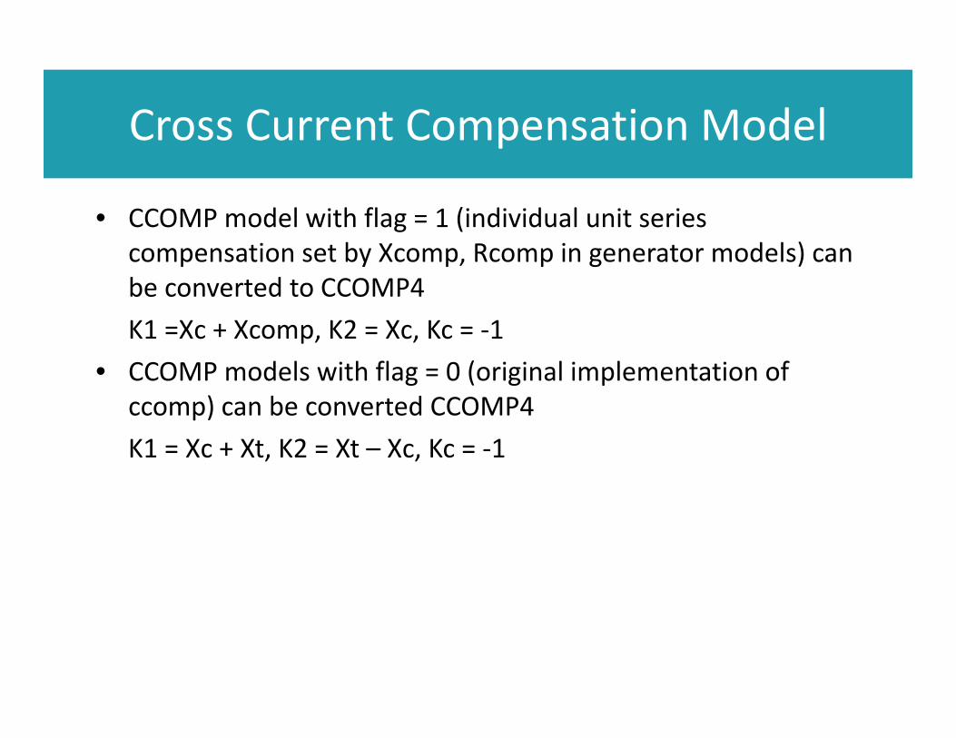
• CCOMP model with flag = 1 (individual unit series compensation set by Xcomp, Rcomp in generator models) can be converted to CCOMP4 K1 =Xc + Xcomp, K2 = Xc, Kc = ‐1
• CCOMP models with flag = 0 (original implementation of ccomp) can be converted CCOMP4 K1 = Xc + Xt, K2 = Xt – Xc, Kc = ‐1

Proposed GENTPW model

Next Step for New Generator Model Development
• Gather/Compile datasets• Develop GENTPW model
– Finalize model structure, including gathering comments/feedback from industry experts
– Write specification– Pseudo code development– Beta version in commercial software platform
• Benchmarking GENSAL, GENROU, GENTPJ and GENTPW model with test data

Turbine‐Governor h6e Model Update
• The initialization part of the h6e model has been changed to an explicit from that gives better assurance of a clean start
• The latest code was sent to software vendors

Dynamic Data Error ListModel Name Parameter Error Notes
regc_a/pv1g/wt4g accel accel = 0 0 < accel < 1
regc_a/pv1g/wt4g mva mva < pgen mva base > PGEN
reec trv Trv = 0 Trv > 0
reec kvi
warning: kvi >= 100 is likely to exhibit voltage oscillation
Kvi is the most critical parameter for reactive current control. High kvi causes overshooting of voltage control. It should be tuned and validated.
repc_a outflagoutflag = 0 for voltage control
If Mon_i and mon_j are absent from the invocation and refflg = 1, then outflag should be 1
repc_a Kc
warning: Kc > 0, but mon_i and mon_j are not provided in the invocation
voltage droop control is not activated if mon_i and mon_jare not provided
reec and repcpfflag, vflag, qflag, refflag
The set of these four flags do not match any of the reactive power control options
lhfrt dftrp, dttrp not PRC‐024 compliantdftrp is frequency change in Hz, not %

HVDC Modeling

LCC‐HVDC Modeling
• The simple LCC‐HVDC model specification was issued in 2015• HVDC TF webcast meeting on 7/26/2017
– Discussed test plan for chvdc2 beta releases in commercial tools– Commercial tool vendors made every effort to complete beta
implementation
• August 23, 2017 issued test plan and test system plus test simulation results to TF
• Results memo released 9/28/2017

LCC‐HVDC Modeling
• LCC‐HVDC model test case

LCC‐HVDC Modeling
• LCC‐HVDC model test results
• The LCC‐HVDC dynamic model was unanimously approved by MVWG

VSC‐HVDC Modeling
• Have implemented it as epcl code• Code done and debugged• Will come back to HVDC TF once more substantial results for
consultation amongst group• Then come back to MVWG to start process of commercial
software tool beta implementation and testing

High Level Documentation of PDCI and IPP
• High –level documentation on control strategy for PDCI and IPP are done.
• ABB internal review is in progress, to be followed by owner/operator review before releasing to WECC MVWG

RAS and Relay Modeling

Global line relay monitoring model
• The global line relay monitoring model specification approved at June MVWG meeting
• It has been implemented to commercial software platforms• The global line relay monitoring model gives Transmission
Planners a capability to comply with NERC TPL standard requirement
• There is still issue for the line relay applied to multi‐section, series‐compensated lines
• MVWG may form a Relay Task Force to solve all the relay protection issues

RAS model
• Status of DOE RAS/SPS modeling project– Survey of RAS/SPS modeling practice for planning and operational
studies– Identification of RAS examples and operation logics in a commercial
software platform for use case development– Development of adaptive algorithms for calculating RAS settings with
HPC techniques– Prototype development in commercial software– Demonstration of the prototype– Outreach activities

WECC Approved Dynamic Model List

WECC Approved Dynamic Model List
• The latest approved dynamic model list is available at WECC website
• https://www.wecc.biz/Reliability/Approved%20Dynamic%20Models%20October%202017.pdf

Next MVWG Meetings

Next MVWG Meetings
• 1st MVWG Meeting– January 24 pm – January 26 am, 2018 Salt Lake City, UT
• 2nd MVWG Meeting– May 23 pm – May 25 am, 2018 Salt Lake City, UT
• 3rd MVWG Meeting– October 22 pm – October 24 am, 2018 Salt Lake City, UT

Questions ?