mvs/csc 7.0 operator's guide - revision ab - oracle documentation
TRANSCRIPT
Submit comments about this document by clicking the Feedback [+] link at: http://docs.sun.com
StorageTek Client System Component
for MVS Environments
Operator’s Guide
Version 7.0
June 2010Revision AB

ii June 2010 Revision AB
MVS/CSC 7.0 Operator’s Guide
Copyright © 2009, 2010, Oracle and/or its affiliates. All rights reserved.
This software and related documentation are provided under a license agreement containing restrictions on use and disclosure and are protected by intellectual property laws. Except as expressly permitted in your license agreement or allowed by law, you may not use, copy, reproduce, translate, broadcast, modify, license, transmit, distribute, exhibit, perform, publish, or display any part, in any form, or by any means. Reverse engineering, disassembly, or decompilation of this software, unless required by law for interoperability, is prohibited.
The information contained herein is subject to change without notice and is not warranted to be error-free. If you find any errors, please report them to us in writing.
If this is software or related software documentation that is delivered to the U.S. Government or anyone licensing it on behalf of the U.S. Government, the following notice is applicable:
U.S. GOVERNMENT RIGHTS Programs, software, databases, and related documentation and technical data delivered to U.S. Government customers are "commercial computer software" or "commercial technical data" pursuant to the applicable Federal Acquisition Regulation and agency-specific supplemental regulations. As such, the use, duplication, disclosure, modification, and adaptation shall be subject to the restrictions and license terms set forth in the applicable Government contract, and, to the extent applicable by the terms of the Government contract, the additional rights set forth in FAR 52.227-19, Commercial Computer Software License (December 2007). Oracle USA, Inc., 500 Oracle Parkway, Redwood City, CA 94065.
This software or hardware is developed for general use in a variety of information management applications. It is not developed or intended for use in any inherently dangerous applications, including applications which may create a risk of personal injury. If you use this software or hardware in dangerous applications, then you shall be responsible to take all appropriate fail-safe, backup, redundancy, and other measures to ensure the safe use. Oracle Corporation and its affiliates disclaim any liability for any damages caused by use of this software or hardware in dangerous applications.
Oracle is a registered trademark of Oracle Corporation and/or its affiliates. Oracle and Java are registered trademarks of Oracle and/or its affiliates. Other names may be trademarks of their respective owners.
AMD, Opteron, the AMD logo, and the AMD Opteron logo are trademarks or registered trademarks of Advanced Micro Devices. Intel and Intel Xeon are trademarks or registered trademarks of Intel Corporation. All SPARC trademarks are used under license and are trademarks or registered trademarks of SPARC International, Inc. UNIX is a registered trademark licensed through X/Open Company, Ltd.
This software or hardware and documentation may provide access to or information on content, products, and services from third parties. Oracle Corporation and its affiliates are not responsible for and expressly disclaim all warranties of any kind with respect to third-party content, products, and services. Oracle Corporation and its affiliates will not be responsible for any loss, costs, or damages incurred due to your access to or use of third-party content, products, or services.
Revision AB iii
Contents
Preface ix
Related Documentation x
Documentation, Support, and Training xi
Oracle Welcomes Your Comments xi
Additional Information xii
1. Introduction 1
Overview 1
MVS/CSC Operating Environment 2
MVS/CSC Basic Functions 2
MVS/CSC System Interfaces 3
MVS/CSC Configurations 3
Security Administration Considerations for Communication 5
StorageTek Library Control System (LCS) Software Products 5
Third-Party Software Interaction 7
Tape Management Systems 7
Multi-image Manager (MIM) 7
Data Facility Hierarchical Storage Manager (DFHSM) 7
System Authorization Facility (SAF) 8
MVS/CSC Interaction With Fault Analyzer for z/OS 8
Communication Methods 9
User Policy Definition for Mixed Media and Devices 12
Device Preferencing 12
DFSMS/MVS Storage Management Subsystem Support 12

iv MVS/CSC 7.0 Operator’s Guide • June 2010 Revision AB
2. Operating the MVS/CSC 13
Overview 13
Operator Interfaces 13
MVS/CSC Operations 14
Pre-Initializing the MVS/CSC 14
Starting the MVS/CSC 15
Stopping the MVS/CSC 16
Manual Mode Operations 18
Manual Mode Operations for the UNIX-Based LCS 18
Manual Mode Operations for the VM-Based LCS 20
LSM Manual Mode Procedures 21
3. Commands 29
Overview 29
Command Format 30
Specifying MVS/CSC Commands 30
Specifying MVS Commands 31
Specifying HSC and CLS Commands 31
MVS/CSC Command Descriptions 32
ALTer Command 32
Parameter Descriptions 32
Example of ALTer TRACDEST Command 33
Display Command 34
LIst Command 40
LOad Command 42
LOG Command 43
MODify Command 44
RESYNCh Command 46
Trace Command 47
4. Operator Console Interface 51
Overview 51
MVS Operator Console Interface 51
HSC Commands 52

Revision AB Contents v
CLS Commands 53
Operator Response 53
5. Software Diagnostic Tools and Recovery Procedures 55
Overview 55
Synchronization and System Recovery Processing 55
Synchronization Recovery Processing 56
System Recovery Processing 57
Recovery Procedures 57
Availability and Heartbeat Message Processing (VM-based LCS) 58
Availability Message Processing 58
Heartbeat Logic 58
Event Log Facility 59
Trace Facility 60
Operator Recovery Procedures 61
A. Gathering Diagnostic Materials 63
Overview 63
MVS Diagnostic Materials 63
Tape Format 64
B. List of Abbreviations 65
Glossary 69
Index 85


Revision AB vii
Figures
FIGURE 1-1 MVS/CSC to LCS Configuration 4
FIGURE 1-2 Communications Using TCP/IP and SNA LU6.2 (Unix-Based LCS) 10
FIGURE 1-3 Communications Using TCP/IP and VTAM “3270 BISYNC” (VM-Based LCS) 11


Revision AB ix
Preface
This guide provides operational information for Oracle’s StorageTek Client System Component for MVS Environments (MVS/CSC) software. It is intended for storage administrators, system programmers and operators responsible for maintaining MVS/CSC.
x MVS/CSC 7.0 Operator’s Guide • June 2010 Revision AB
Related DocumentationThe following list contains the names of publications that provide additional information about MVS/CSC.
The documentation is available online at:
http://docs.sun.com
Oracle’s StorageTek Client System Component for MVS Environments (MVS/CSC)■ MVS/CSC Configuration Guide■ MVS/CSC Messages and Codes Guide ■ MVS/CSC Syntax Quick Reference■ MVS/CSC System Programmer’s Guide
Oracle’s StorageTek Enterprise Library Software (ELS)■ Introducing ELS■ Installing ELS■ ELS Command, Control Statement, and Utility Reference■ ELS Syntax Quick Reference■ ELS Messages and Codes■ ELS Programming Reference■ ELS Legacy Interfaces Reference■ Configuring HSC and VTCS■ Managing HSC and VTCS■ Configuring and Managing SMC■ ELS Disaster Recovery and Offsite Data Management Guide
Oracle’s StorageTek Automated Cartridge System Library Software (ACSLS) Publications for the UNIX-Based LCS■ ACSLS Installation, Configuration and Administration Guide■ ACSLS Messages ■ ACSLS Reference
Revision AB Preface xi
Documentation, Support, and Training
Oracle Welcomes Your CommentsOracle is interested in improving its documentation and welcomes your comments and suggestions. Submit your comments by clicking the Feedback link at:
http://docs.sun.com
Function URL
Oracle Home http://oracle.com
Documentation http://docs.sun.com
Support http://www.sun.com/support
Training http://www.oracle.com/global/us/education/sun_select_country.html

xii MVS/CSC 7.0 Operator’s Guide • June 2010 Revision AB
Additional Information
Customer-initiated Maintenance Customer-initiated maintenance begins with a telephone call from you to Oracle StorageTek Support. You receive immediate attention from qualified Oracle personnel, who record problem information and respond with the appropriate level of support.
To contact Oracle StorageTek Support about a problem:
1. Use the telephone and call:
☎ 800.872.4786 (1.800.USA.4SUN) (inside the United States)
☎ 800.722.4786 (Canada)
For international locations:
http://www.sun.com/contact/support.jsp
2. Describe the problem to the call taker. The call taker will ask several questions and will either route your call to or dispatch a support representative.
If you have the following information when you place a service call, the process will be much easier:
Account name
Site location number
Contact name
Telephone number
Equipment model number
Device address
Device serial number (if known)
Urgency of problem
Fault Symptom Code (FSC)
Problem description

Revision AB Preface xiii
Conventions for Reader Usability
Typographic
Some JCL examples in this guide include italic type. Italic type is used to indicate a variable. You must substitute an actual value for these variables.
The use of mixed upper and lower case characters for commands, control statements, and parameters indicates that lower case letters may be omitted to form abbreviations. For example, you may simply enter POL when executing the POLicy command.
Syntax Flow Diagrams
Syntax flow diagramming conventions include the following:
Flow Lines
Syntax diagrams consist of a horizontal base line, horizontal and vertical branch lines, and the text for a command, control statement, macro, or utility. Diagrams are read left to right, and top to bottom. Arrows indicate flow and direction.
Single Required Choice
Branch lines (without repeat arrows) indicate that a single choice must be made. If one of the items to choose from is positioned on the baseline of the diagram, one item must be selected.
COMMAND/MACRO/UTILITY Item 1Item 2Item 3
Item 1Item 2Item 3

xiv MVS/CSC 7.0 Operator’s Guide • June 2010 Revision AB
Single Optional Choice
If the first item is positioned on the line below the baseline, one item may be optionally selected.
Defaults
Default values and parameters appear above the baseline.
Some keyword parameters provide a choice of values in a stack. When the stack contains a default value, the keyword and the value choices are placed below the base line to indicate that they are optional, and the default value appears above the keyword line.
Repeat Symbol
A repeat symbol indicates that more than one choice can be made or that a single choice can be made more than once. The following example indicates that a comma is required as the repeat delimiter.
Item 1Item 2Item 3
Default
KeywordValue3
Default ValueValue2
,variable

Revision AB Preface xv
Keywords
All command keywords are shown in all upper case or in mixed case. When commands are not case sensitive, mixed case implies that the lowercase letters may be omitted to form an abbreviation.
Variables
Italic type is used to indicate a variable.
Alternatives
A bar ( | ) is used to separate alternative parameter values.
Optional
Brackets [ ] are used to indicate that a command parameter is optional.
Delimiters
If a comma (,), a semicolon (;), or other delimiter is shown with an element of the syntax diagram, it must be entered as part of the statement.
Ranges
An inclusive range is indicated by a pair of elements of the same length and data type, joined by a dash. The first element must be strictly less than the second element.
A hexadecimal range consists of a pair of hexadecimal numbers (for example, 0A2-0AD, or 000-0FC).
A decimal range consists of a pair of decimal numbers (i.e., 1-9, or 010-094). Leading zeros are not required. The decimal portion is referred to as an incremental range. The character positions of the incremental portion of both range elements must match, and the non incremental characters of the first element must be identical to those of the second element.
A numeric VOLSER range (vol-range) consists of a pair of VOLSER elements containing a decimal numeric portion of 1 to 6 digits (for example, ABC012-ABC025, or X123CB-X277CB). The decimal portion is referred to as an incremental range. The following additional restrictions apply:
■ The character positions of the incremental portion of both range elements must match.
■ The non incremental characters of the first element must be identical to those of the second element.
■ You cannot increment two portions of a range element. If 111AAA is the first element, you cannot specify 112AAB for the second element.
xvi MVS/CSC 7.0 Operator’s Guide • June 2010 Revision AB
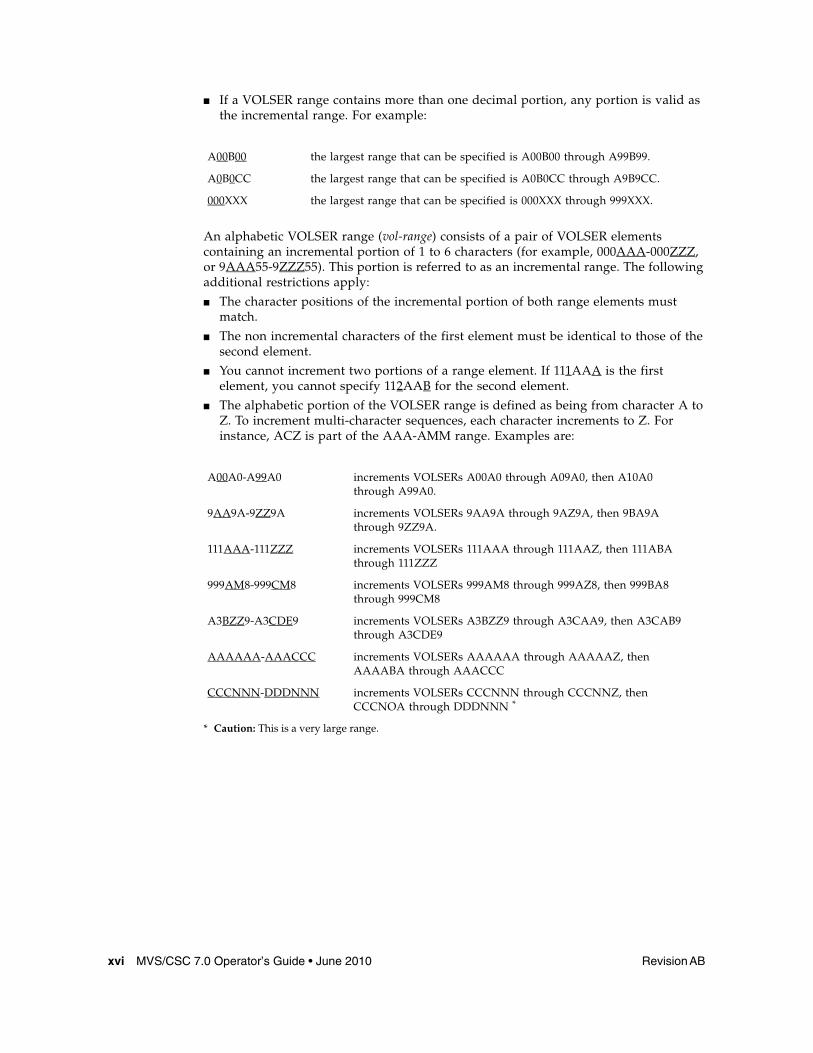
■ If a VOLSER range contains more than one decimal portion, any portion is valid as the incremental range. For example:
An alphabetic VOLSER range (vol-range) consists of a pair of VOLSER elements containing an incremental portion of 1 to 6 characters (for example, 000AAA-000ZZZ, or 9AAA55-9ZZZ55). This portion is referred to as an incremental range. The following additional restrictions apply:
■ The character positions of the incremental portion of both range elements must match.
■ The non incremental characters of the first element must be identical to those of the second element.
■ You cannot increment two portions of a range element. If 111AAA is the first element, you cannot specify 112AAB for the second element.
■ The alphabetic portion of the VOLSER range is defined as being from character A to Z. To increment multi-character sequences, each character increments to Z. For instance, ACZ is part of the AAA-AMM range. Examples are:
A00B00 the largest range that can be specified is A00B00 through A99B99.
A0B0CC the largest range that can be specified is A0B0CC through A9B9CC.
000XXX the largest range that can be specified is 000XXX through 999XXX.
A00A0-A99A0 increments VOLSERs A00A0 through A09A0, then A10A0 through A99A0.
9AA9A-9ZZ9A increments VOLSERs 9AA9A through 9AZ9A, then 9BA9A through 9ZZ9A.
111AAA-111ZZZ increments VOLSERs 111AAA through 111AAZ, then 111ABA through 111ZZZ
999AM8-999CM8 increments VOLSERs 999AM8 through 999AZ8, then 999BA8 through 999CM8
A3BZZ9-A3CDE9 increments VOLSERs A3BZZ9 through A3CAA9, then A3CAB9 through A3CDE9
AAAAAA-AAACCC increments VOLSERs AAAAAA through AAAAAZ, then AAAABA through AAACCC
CCCNNN-DDDNNN increments VOLSERs CCCNNN through CCCNNZ, then CCCNOA through DDDNNN *
* Caution: This is a very large range.

Revision AB Preface xvii
The number of volumes in an alphabetic VOLSER range depends on the number of elements in the incrementing portion of the VOLSER range. For an A to Z range in each character position, the number of volumes can be calculated by 26 to the power of the number of positions that are being incremented.
Lists
A list consists of one or more elements. If more than one element is specified, the elements must be separated by a comma or a blank space, and the entire list must be enclosed in parentheses.
Blanks
Keyword parameters and values may be separated by any number of blanks.
Control Statements
The standard syntax conventions for control statements are as follows:
■ The only valid control statement information area is from column 1 to column 72. Columns 73-80 are ignored.
■ Parameters may be separated by one or more blanks or a comma.
■ A value is associated with a parameter by an equal (=) sign or by enclosing the value in parentheses, and concatenating it immediately after the parameter.
■ Case (upper or lower) is ignored in actual control statements.
■ Continuations are supported by including a plus (+) sign at the end of the line to be continued. A control statement is terminated if the statement is not continued.
■ /* and */ can be used to enclose comments in the job stream. Comments can be continued over multiple lines, but cannot be nested.
PARMLIB members must include a /*...*/ comment as the first control statement. Otherwise, the old format is assumed. Comments in the old format must begin with an asterisk (*) in column 1.
For definition data sets (e.g., VOLATTRs, UNITATTRs and TAPEREQs), comments must be in the new format (/*...*/).
■ Asterisk (*) comments are not allowed.
■ A /*...*/ comment in the first line is not required.
■ The maximum length for a control statement is 1024 characters.
A-Z 261 26
AA-ZZ 262 676
AAA-ZZZ 263 17,576
AAAA-ZZZZ 264 456,976
AAAAA-ZZZZZ 265 11,881,376
AAAAAA-ZZZZZZ 266 308,915,776


Revision AB 1
CHAPTER
1
Introduction
OverviewMVS/CSC provides client functions and communications between an MVS host and the Library Control System (LCS) or server residing on a Unix or VM host.
When combined with the LCS and SMC, the MVS/CSC provides the following benefits:
■ a library shared by multiple host systems (both IBM and non-IBM)
■ secondary library attachment for remote backup
■ library attachment to more than sixteen MVS hosts, with MVS/CSC installed on each attached host system
Note – MVS/CSC 7.0 is not compatible with StorageTek LibraryStation. In an MVS-only environment, you must use StorageTek SMC and its HTTP server subtask to provide communication between MVS hosts. Refer to the publication Configuration and Managing SMC for more information.
This chapter summarizes the following MVS/CSC features and functions:
■ MVS/CSC operating environment■ MVS/CSC basic functions■ MVS/CSC system interfaces■ MVS/CSC configurations■ StorageTek LCS software products■ Third-party software products that coexist with MVS/CSC■ Communications methods used to transmit commands to the LCS■ Mixed media and devices for the UNIX-based LCS
MVS/CSC Operating Environment
2 MVS/CSC 7.0 Operator’s Guide • June 2010 Revision AB
MVS/CSC Operating EnvironmentMVS/CSC operates with the Storage Management Component (SMC) on any IBM or compatible processor running MVS (any IBM-supported version of z/OS). The MVS/CSC supports both JES2 and JES3 environments. Except for noted differences, the information in this publication applies to both JES2 and JES3 environments.
In addition, references in this publication to JES2 apply to both JES2 environments and JES3 environments that run without TAPE SETUP processing; references to JES3 apply only to JES3 environments that run with TAPE SETUP processing.
MVS/CSC Basic FunctionsThe MVS/CSC’s primary functions are to provide user policy information to the SMC and to transmit information requests and directives to the appropriate LCS.
The SMC manages the following functions:
■ Drive allocation
■ Processing of Mount, Dismount, and Swap messages on MVS systems. If a message requests an MVS/CSC drive, the SMC routes the request to the MVS/CSC.
Refer to the publication Configuring and Managing SMC for more information.
Once the cartridge is mounted, the data is transferred using the data path under the control of the MVS client operating system.
Depending on the configuration, the MVS/CSC communicates with the LCS using one of the following communications methods:
■ Virtual Telecommunications Access Method (VTAM) “3270 BISYNC”■ Systems Network Architecture Logical Unit 6.2 (SNA LU 6.2)■ Transmission Control Protocol/Internet Protocol (TCP/IP)
The MVS/CSC translates each request to the command format appropriate for the LCS.
In addition to basic functions provided to start and stop the MVS/CSC software, the MVS/CSC provides diagnostic aids (event logging and tracing), utility functions, user exits, and recovery processing. The MVS/CSC also provides an operator interface on MVS consoles through which you can issue commands to MVS/CSC. For the VM-based LCS, commands can be forwarded to the CLS or VM/HSC using the communications link.
MVS/CSC System Interfaces
Revision AB Chapter 1 Introduction 3
MVS/CSC System InterfacesThe MVS/CSC consists of the following system interfaces:
■ Tape management system interfaces to communicate with your tape management system
■ Communications interfaces to link the MVS/CSC to the LCS for sending and receiving messages
■ Operator console interfaces to allow operator commands to be issued for the MVS/CSC
■ Programmatic interface to allow programs to request certain services from the MVS/CSC (UNIX-based LCS only)
MVS/CSC ConfigurationsThe MVS/CSC program runs as a subsystem on the IBM MVS operating system along with the SMC subsystem.
MVS/CSC can coexist with the MVS Host Software Component (MVS/HSC) on the same MVS host, thus providing access to multiple libraries from a single MVS host environment. This allows the MVS/HSC to control a local primary library complex1
while one or more MVS/CSC subsystems access secondary, possibly remote libraries.
When multiple MVS/CSCs (or an HSC with one or more MVS/CSCs) exist on the same MVS host, the SMC on this host determines whether to use the HSC or any of the MVS/CSCs to process a particular allocation or Mount/Dismount/Swap message event. Refer to the publication Configuring and Managing SMC for more information.
Each MVS/CSC can communicate with only one LCS at a time. In turn, each LCS manages a single library complex. Multiple MVS/CSC subsystems can exist on a single MVS host system, and each MVS/CSC subsystem can be attached to a different LCS. MVS/CSC supports the following LCS platforms:
■ UNIX-based■ VM-based
1. A library complex consists of one HSC Control Data Set (CDS) and a maximum of 256 Automatic Cartridge Systems (ACSs). Each ACS can contain a maximum of 24 Library Storage Modules (LSMs).
MVS/CSC Configurations
4 MVS/CSC 7.0 Operator’s Guide • June 2010 Revision AB
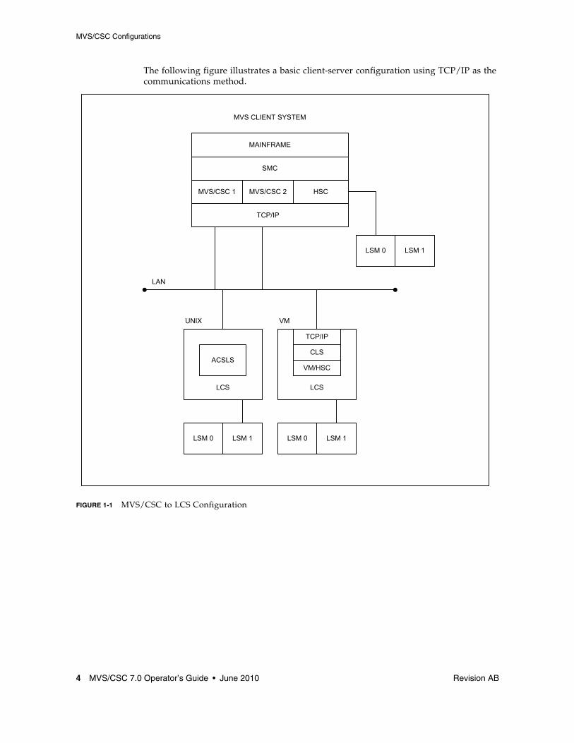
The following figure illustrates a basic client-server configuration using TCP/IP as the communications method.
FIGURE 1-1 MVS/CSC to LCS Configuration
LSM 0 LSM 1LSM 0 LSM 1
LSM 0 LSM 1
MVS/CSC 1 MVS/CSC 2 HSC
MAINFRAME
SMC
TCP/IP
ACSLS
LCS LCS
TCP/IP
CLS
VM/HSC
LAN
UNIX VM
MVS CLIENT SYSTEM

Security Administration Considerations for Communication
Revision AB Chapter 1 Introduction 5
Security Administration Considerations for Communicationz/OS users must define an OMVS segment in RACF for the userid associated with MVS/CSC. If this is not done, a UNIX process initialization failure occurs. To define the OMVS segment, refer to the IBM Communications Server IP Migration Guide.
If you are running a functionally equivalent security product (e.g., ACF2), refer to the documentation for that product.
StorageTek Library Control System (LCS) Software ProductsThe StorageTek LCS is the control interface between the mainframe computer systems (client systems) and the StorageTek library products. The LCS consists of hardware and software products that are attached to the MVS/CSC through a communications link.
The MVS/CSC receives requests from the SMC or the MVS host system and translates them to messages, which it sends to the LCS. The LCS receives the requests from the MVS/CSC to perform the automated handling of library cartridges. The LCS directs and monitors a single library and manages message and request traffic from one or more connected client systems. The LCS determines where the cartridge resides.
The LCS controls the library and manages the library database, which contains volume location and volume attribute information for all cartridges within the library. The LCS also performs activities such as mounting, dismounting, and entering and ejecting cartridges. The Library Management Unit (LMU) manages the movement (or exchanges) of cartridges between the Library Storage Modules (LSMs).
The MVS/CSC can be attached to either of the following LCSs:
■ UNIX-based LCS, which consists of the Automated Cartridge System Library Software (ACSLS)
■ VM-based LCS, which consists of the Host Software Component for VM (VM/HSC) and the Common Library Services (CLS)
Each LCS is described in more detail in the following sections.
Note – Refer to the publication Installing ELS for information about ELS hardware and software requirements.

StorageTek Library Control System (LCS) Software Products
6 MVS/CSC 7.0 Operator’s Guide • June 2010 Revision AB
UNIX-Based LCSThe UNIX-based LCS consists of the StorageTek ACSLS software product. ACSLS consists of a system administration component, interfaces to client system applications, and library management facilities that support the entire family of Nearline Automated Cartridge Systems.
The UNIX-based LCS resides on a UNIX-based platform. The MVS/CSC using the UNIX-based LCS requires that the ACSLS software be installed.
VM-based LCSThe VM-based LCS consists of the following StorageTek software products:
■ Host Software Component for VM (VM/HSC)■ Common Library Services (CLS)
Host Software Component (HSC) controls the ACS. It runs as a VM application on the VM-based LCS. The library database records cell status, characteristics, and disposition of all cartridges stored in the library.
Common Library Services (CLS) provides the communications interface between the client system (in this case MVS) and the VM/HSC. The CLS receives client requests and translates them to a form that can be executed by the HSC.
The VM-based LCS resides on an IBM System 370 processor running the Virtual Machine (VM) operating system. The MVS/CSC using the VM-based LCS requires that the CLS and VM/HSC software be installed.
Third-Party Software Interaction
Revision AB Chapter 1 Introduction 7
Third-Party Software InteractionThe MVS/CSC subsystem operates in conjunction with various other third-party software, including:
■ CA-1 (TMS) and CA-DYNAM/TLMS Tape Management Systems ■ Data Facility Hierarchical Storage Manager (DFHSM) ■ MIM ■ AutoMedia (Zara) Tape Management System■ Any System Authorization Facility (SAF) compliant software product
Note – Only those third-party software products known to coexist with MVS/CSC are listed above.
Tape Management SystemsThe MVS/CSC provides support for the following tape management products:
■ CA-1■ CA-DYNAM/TLMS (Tape Library Management System)■ AutoMedia (Zara)
Interaction with tape management systems is managed by the Storage Management Component (SMC). Refer to the publication Configuring and Managing SMC for more information.
Multi-image Manager (MIM)MIM is a third-party software product that is used in a multi-CPU environment to control the allocation of transports to a particular host. The MVS/CSC can coexist with MIM. However, you must follow certain procedures when using MIM with the MVS/CSC. Refer to the MVS/CSC Configuration Guide for information about MIM restrictions.
Note – With MIM Release 2.0, there are no restrictions for startup and no restrictions on MIM features.
Data Facility Hierarchical Storage Manager (DFHSM)The MVS/CSC supports the use of 3480, 3490, 3490E, 3590, and helical-type transports by DFHSM. MVS/CSC supports dynamic allocation of cartridge transports by DFHSM.

MVS/CSC Interaction With Fault Analyzer for z/OS
8 MVS/CSC 7.0 Operator’s Guide • June 2010 Revision AB
System Authorization Facility (SAF)The MVS/CSC operates with and does not compromise the integrity of any security facility using the SAF interface.
MVS/CSC Interaction With Fault Analyzer for z/OSThe IBM program Fault Analyzer for z/OS is used to determine why an application abends. It may be installed on systems that also run StorageTek ELS software, however, it is not useful when applied to abends that occur in ELS code. Because of the complex subsystem environment where ELS code executes, Fault Analyzer itself may abend.
If Fault Analyzer for z/OS is installed on your ELS system, it is strongly recommended that you specify the following update to ensure that this product ignores ELS product abends.
When Fault Analyzer is installed, perform the following update to SYS1.PARMLIB(IDICNF00):EXCLUDE (NAME(HSC) NAME(SMC) NAME(CSC))
where:
■ HSC is the name of the HSC console-started-task■ SMC is the name of the SMC console-started-task■ CSC is the name of the MVS/CSC console-started-task.
Alternatively, you can specify EXCLUDE (TYPE(STC)) to exclude all console-started tasks from evaluation by Fault Analyzer. However, this broad exclusion may not be appropriate in your environment.
Communication Methods
Revision AB Chapter 1 Introduction 9
Communication MethodsThe MVS/CSC subsystem is connected to the LCS using a communications link. The following list describes the communications links that can be used to connect the MVS/CSC:
■ Transmission Control Protocol/Internet Protocol (TCP/IP) is used by the VM-based and UNIX-based LCS. You can use the following software for TCP/IP communications:
■ IBM TCP/IP■ CA Unicenter TCPaccess Communications Server■ CA Unicenter TCPaccess X.25 server
■ Virtual Telecommunications Access Method (VTAM) is divided into two categories:
■ VTAM for “3270 BISYNC” communications, which is used only by the VM-based LCS
■ VTAM for SNA LU 6.2 communications, which is used by the UNIX-based LCS
Note – Refer to the publication Installing ELS for supported communication software release levels.

Communication Methods
10 MVS/CSC 7.0 Operator’s Guide • June 2010 Revision AB
The following figure shows the communications connections using the TCP/IP communications protocol and the SNA LU 6.2 communications protocol for a UNIX-based LCS.
Note – The data path is not shown in this illustration.
FIGURE 1-2 Communications Using TCP/IP and SNA LU6.2 (Unix-Based LCS)
LSM 0 LSM 1LSM 0 LSM 1
MVS/CSC
MVS
APPC/MVS
SMC VTAM
MVS/CSC TCP/IP
SMC
MVS
IBM SNA NETWORK CPA
ACSLS
LMULCU LCU LMU
DATABASE
ACS0 ACS1

Communication Methods
Revision AB Chapter 1 Introduction 11
The following figure shows the TCP/IP and VTAM “3270 BISYNC” communications protocol for a VM-based LCS.
Note – The data path is not shown in this illustration.
FIGURE 1-3 Communications Using TCP/IP and VTAM “3270 BISYNC” (VM-Based LCS)
LSM 0 LSM 1LSM 0 LSM 1
MVS/CSC
MVS
SMC
VTAM MVS/CSC TCP/IP
SMC
MVS
CPA
VM PASS THROUGH FACILITY (PVM)
ACS0 ACS1
37x5
TCP/IP
COMMON LIBRARY SERVICES (CLS)
VM/HSCCDS
CDSVM/SP

DFSMS/MVS Storage Management Subsystem Support
12 MVS/CSC 7.0 Operator’s Guide • June 2010 Revision AB
User Policy Definition for Mixed Media and DevicesThe MVS/CSC supports mixed media and mixed cartridge transports in an ACS for the UNIX-based LCS. Mixed media and cartridge transport devices are not supported for the VM-based LCS.
The 4400 ACS supports a mixture of transports and associated media, including 4480, 4490, 9490, 9490EE, SD-3 (helical), T9840 series, and T9940 series transports.
The SL8500 ACS supports a mixture of T9840 and T9940 series transports and associated media. These are the only transports supported for the SL8500.
The Storage Management Component (SMC) calls on MVS/CSC policies in order to perform drive exclusion and Mount/Dismount/Swap processing in a library environment containing mixed media and cartridge transport devices. This support does not require changes to JCL or the invocation of MVS/CSC user exits. Refer to the publication Configuring and Managing SMC for more information.
SMC TAPEREQ control statements are used to specify tape request attributes. These statements are used to place a data set that meets the criteria specified by the TAPEREQ attributes on a specific media type, and create a data set using a specific recording technique. Refer to the publication ELS Command, Control Statement, and Utility Reference for more information about the SMC Tapereq control statement.
Device PreferencingDevice preferencing is applicable only to library configurations containing a mixture of StorageTek’s 36-track 4490, 9490, and 9490EE Cartridge Subsystems. It is managed by the Storage Management Component (SMC). Refer to the publication Configuring and Managing SMC for more information.
DFSMS/MVS Storage Management Subsystem SupportUser policy specification via SMS is supported by the Storage Management Component (SMC). Refer to the publication Configuring and Managing SMC for more information.

Revision AB 13
CHAPTER
2
Operating the MVS/CSC
OverviewThis chapter describes how to use the MVS/CSC to access library services. It describes the following:
■ Operator interfaces
■ MVS/CSC operations, including starting and stopping the MVS/CSC
■ Manual mode operations for the UNIX-based and VM-based Library Control System (LCS)
Operator InterfacesMVS/CSC provides an operator interface through the MVS system console. The operator interface provides commands for:
■ Starting and stopping the MVS/CSC ■ Displaying MVS/CSC information ■ Altering MVS/CSC configuration ■ Invoking MVS/CSC recovery processing ■ Enabling MVS/CSC diagnostics
Depending on the server environment, other consoles may be provided.
■ For the UNIX-based LCS, the ACS System Administrator (ACSSA) console provides access to the LCS and the library.
■ For the VM-based LCS, the MVS system console provides an operator interface to both the MVS/CSC and the VM-based LCS for controlling the library. During normal operations, facilities that are part of the Host Software Component (HSC) and the Common Library Services (CLS) can be initiated from the MVS system console. The LCS processor console and the CLS operator console also provide access to the library. See Chapter 4, “Operator Console Interface” for more information.

MVS/CSC Operations
14 MVS/CSC 7.0 Operator’s Guide • June 2010 Revision AB
MVS/CSC OperationsThe following sections describe normal MVS/CSC operations, including:
■ Pre-initializing the MVS/CSC ■ Starting the MVS/CSC ■ Stopping the MVS/CSC
Pre-Initializing the MVS/CSCBoth the MVS/CSC and the LCS must be initialized before the library can be accessed. The MVS/CSC can either be pre-initialized by the MVS subsystem pre-initialization routine during the initial program load (IPL) of the MVS host system, or by issuing the MVS SETSSI command to dynamically define the MVS subsystem name.
The subsystem pre-initialization routine is identified in the MVS IEFSSNyy member of SYS1.PARMLIB. The pre-initialization routine is executed once for each IPL of the MVS host system. The pre-initialization routine establishes unique identification of the MVS/CSC subsystems in the MVS host system. Once the IPL of MVS has completed and the pre-initialization routine has executed, you can start the MVS/CSC subsystem.
Issuing the MVS Start command invokes the subsystem initialization routine. This routine determines what parameters are in effect, initializes communications, performs any cleanup necessary (such as resource recovery), and begins normal processing.
Before initialization of the MVS/CSC, the MVS/CSC startup parameters must be specified. These parameters reside in a member of a partitioned data set or in a sequential data set. The parameters are identified by the SCSPARM DD name in the MVS/CSC startup procedure.
During MVS/CSC startup processing, the MVS/CSC synchronizes the state of its resources with the LCS and MVS using its synchronization processing. For the VM-based LCS, the MVS/CSC sends an availability message to the CLS during initialization. The MVS/CSC waits for a return availability message from the CLS before processing can occur.
Note – MVS/CSC can be initialized before the SMC without producing error messages. However, an SMC subsystem must be active to influence tape allocations and intercept MVS messages.

MVS/CSC Operations
Revision AB Chapter 2 Operating the MVS/CSC 15
Starting the MVS/CSCThe MVS Start command initializes the MVS/CSC. The syntax of the Start command is:
START or S is the keyword for the MVS Start command. The value specified for csc-proc-name is the name of a member in a procedure library. You can specify the following values for the PRM parameter:
RESET
Instructs the MVS/CSC to reset its internal initialization and termination flags. This parameter may be required if the last execution on the MVS/CSC was terminated by an MVS Force command.
COLD
Instructs the MVS/CSC to rebuild its internal control structures. This parameter is required if migrating from a prior version of the MVS/CSC to this version of MVS/CSC and no IPL of the MVS host system was performed. This parameter may also be required if an MVS/CSC PTF has been applied and no IPL of MVS was performed.
The MVS/CSC system responds by displaying console messages (shown in the following figure). The messages explain that the MVS/CSC subsystem started at the time shown and that initialization completed. Specific messages indicating that a session with the LCS was successfully initialized will be issued depending on the configuration and parameters specified.
START csc-proc-name[,PRM=RESET|COLD]
IEF403I CSC0 - STARTED - TIME=08.45.56SCS0500I COPYRIGHT (C) 1992, 2010, ORACLE AND/OR ITS AFFILIATES.ALL RIGHTS RESERVED......SCS0517I MVS/CSC subsystem CSC0 initialization complete

MVS/CSC Operations
16 MVS/CSC 7.0 Operator’s Guide • June 2010 Revision AB
Stopping the MVS/CSCMVS/CSC processing can be stopped by causing an orderly shutdown or an immediate shutdown.
Orderly Shutdown
During an orderly shutdown, the MVS/CSC waits for processing of all activities in progress to be completed before completing shutdown.
Immediate Shutdown
During an immediate shutdown, the MVS/CSC stops all processing and immediately begins shutdown processing.
Any of the following MVS commands can be used to stop MVS/CSC processing:
■ STOP
The MVS Stop command causes an orderly shutdown of the MVS/CSC.
STOP or P is the keyword for the MVS Stop command. The value specified for csc-proc-name is the name of the MVS/CSC started task currently running.
■ CANCEL
The MVS Cancel command causes all MVS/CSC operations to be cancelled and causes an immediate shutdown of the MVS/CSC.
CANCEL is the keyword for the MVS Cancel command. The value specified for csc-proc-name is the name of the MVS/CSC started task currently running. The optional DUMP parameter instructs the MVS host system to produce a dump of the MVS/CSC address space.
■ FORCE
The MVS Force command causes all MVS/CSC operations to be cancelled and causes an immediate shutdown of the MVS/CSC. However, unlike the Cancel command, the Force command may cause unpredictable results when the MVS/CSC is restarted. Therefore, use of this command is not recommended.
FORCE is the keyword for the MVS Force command. The value specified for csc-proc-name is the name of the MVS/CSC task currently running.
STOP csc-proc-name
CANCEL csc-proc-name,DUMP
FORCE csc-proc-name

MVS/CSC Operations
Revision AB Chapter 2 Operating the MVS/CSC 17
Communications Considerations When Stopping the MVS/CSCThe communications access method software:
■ IBM TCP/IP, or CA Unicenter TCPaccess products■ VTAM for “3270 BISYNC” communications■ APPC/MVS and VTAM for SNA LU 6.2 communications
should be operational before starting the MVS/CSC subsystem. If the communications software must be stopped, the MVS/CSC should be stopped using the MVS Stop (or Cancel) command before stopping the communications software.

Manual Mode Operations
18 MVS/CSC 7.0 Operator’s Guide • June 2010 Revision AB
Manual Mode OperationsThis section describes manual mode operations for:
■ UNIX-based LCS■ VM-based LCS
Manual Mode Operations for the UNIX-Based LCSWhen the ACS or LSM is offline and a mount request is issued for a library transport, the MVS/CSC returns the following message:SCS0917D Mount of volser on drive XXXX failed - LSM offline; reply “C”ancel, “R”etry, or “M”anual mount
A response of “M” to the message results in either of the following messages, depending on whether or not the mount request was for a specific cartridge.SCS0080I Mount of volser on drive XXXX - Volume at AA:LL:PP:RR:CC SCS0080I Mount of on drive XXXX -
For specific requests, the volume serial number (volser), drive address (XXXX), and cartridge location (AA:LL:PP:RR:CC) is supplied. For nonspecific requests, only the drive address (XXXX) is supplied; the volume serial number and cartridge location are not provided.
For the UNIX-based LCS, you can issue the following command from the ACS System Administrator (ACSSA) console to obtain the volume serial number and location of scratch volumes:query scratch x
where x is the pool identifier of the scratch subpool. The default subpool number is 0.
The following example shows the listing that would appear in response to the query, assuming volumes U01102, U01103, and U01104 are available scratch cartridges:11-07-01 13:55:14 Scratch Status Scratch Pool Identifier Home Location Status 0 U01102 0, 0, 4, 1, 1 home 0 U01103 0, 0, 0, 1, 0 home 0 U01104 0, 0, 2, 1, 1 home

Manual Mode Operations
Revision AB Chapter 2 Operating the MVS/CSC 19
After determining the location of the cartridge, unlock and go inside the LSM. For the appropriate transport, press and hold the Rewind button for several seconds (or the Rewind and Unload buttons, depending on the type of transport). This causes the panel lights to flash on the panel corresponding to the transport that requested the mount. For specific cartridge mounts, the panel lights will be alternately flashing the volume serial number and the cartridge location in the LSM. The LSM location will be flashing four numbers representing LSM, panel, row, and column. For scratch cartridge mounts the LSM location will be flashing all zeros.
Locate the cartridge and place it in the designated transport. The lights will flash rewinding, unloading, and so forth. When the MVS job is completed, the cartridge should be removed from the LSM.
To vary the ACS online for the UNIX-based LCS, issue the following command from the ACSSA console:
where x is the ACS identifier.
To vary the LSM online and return it to automatic mode for the UNIX-based LCS, issue the following command from the ACSSA console:
where x is the ACS identifier and y is the LSM identifier.
vary acs x online
vary lsm x,y online

Manual Mode Operations
20 MVS/CSC 7.0 Operator’s Guide • June 2010 Revision AB
If the LSM is offline when a program terminates and MVS issues a dismount message, the MVS/CSC displays the following message:SCS0924D Dismount of volser from drive XXXX failed - LSM offline; reply “M”anual dismount or “R”etry
where volser is the volume identifier and XXXX is the transport identifier.
A response of “R” initiates a software retry. If the LSM was varied online before the “R” response, the volume will be dismounted automatically. If you reply “M” to the message, the volume must be manually removed from the LSM.
Note – It is highly recommended that the Audit command be issued after manual mount processing.
Manual Mode Operations for the VM-Based LCSWhen an LSM is offline or the ACS is disconnected, mount and dismount activity can still continue in manual mode. In manual mode, what is normally accomplished by the robot inside the LSM must be done manually by data center personnel.
The HSC detects the manual-mode condition and issues a message asking if a manual mount should be performed. Any response to the HSC message allows the MVS/CSC to continue with its own operator-intervention messages.
The HSC and MVS/CSC together allow manual-mode operations to continue, including controlling the disposition of the manually mounted cartridge in the library database.
The following sections describe procedures for mounting and dismounting cartridges in a variety of circumstances using manual-mode operations. The descriptions provided in this chapter show how the MVS/CSC interacts with manual-mode messages issued by the HSC. The steps and procedures described here should provide adequate instruction about operating in manual mode.
Manual Mode Operations
Revision AB Chapter 2 Operating the MVS/CSC 21
LSM Manual Mode ProceduresWhen an LSM cannot operate in automatic mode, the robot does not mount and dismount cartridges automatically. You must go inside the LSM and mount and dismount cartridges manually. This section describes the following procedures for operating an LSM in manual mode:
■ Determining that the LSM is not in automatic mode ■ Placing the LSM in manual mode ■ Handling manual mount requests ■ Handling manual dismount requests
Note – Manual mode procedures depend on the tape management system being used, and on whether PROP (Programmable Operator facility) is used. Refer to the documentation for your tape management system. Those procedures supersede the procedures described in this chapter.
Determining That the LSM is Not in Automatic ModeAny of the following are signs that indicate when an LSM is not functioning in automatic mode:
■ The LSM access door is open.
■ The robot does not automatically mount and dismount cartridges.
■ The HSC issues a console message informing the operator that an LSM is “not ready” indicating a problem has been detected in the LSM. The message identifies the LSM and provides a reason code for the failure. Refer to the publication ELS Messages and Codes for an explanation of the reason code.
Displaying LSM Status—If you suspect that the LSM is not functioning in automatic mode, issue the following command at an MVS console to display the status of the LSM:
The status display indicates “not ready” if the LSM is not functioning in automatic mode.
CSCn HSC DISPLAY LSM lsm-id

Manual Mode Operations
22 MVS/CSC 7.0 Operator’s Guide • June 2010 Revision AB
Placing the LSM in Manual ModePlace the LSM in manual mode by issuing the following command at an MVS console:
When the LSM is offline, the following message is displayed on the console: ... LSM AA:LL now OFFLINE
The LSM remains in manual mode until the MODIFY lsm-id ONLINE command is issued and completes successfully.
Verifying the LSM is Offline—If you did not see the “LSMid AA:LL now OFFLINE” message, you can verify that the LSM is offline by issuing the following command at an MVS console:
The status display indicates “OFFLINE” if the Modify command was successful. If the LSM is not offline, reissue the Modify command with the FORCE option.
Note – Placing the LSM offline does not cause the cartridge transports in the affected LSM to become offline.
Manual Mode Dismount Processing for Robot-Mounted Cartridges—Placing an LSM in manual mode does not cause the cartridge transports in the affected LSM to become offline. Jobs that are running when an LSM is modified offline continue without interruption. As the jobs complete, manual dismount requests are issued for cartridges that were mounted by the robot before the LSM was modified offline.
Normal HSC manual mode processing deletes a cartridge from the library database when the dismount message is displayed. The HSC considers the dismount complete; it cannot be displayed as an outstanding request. This type of processing assumes the operator manually dismounts the cartridge and removes it from the LSM. Cartridges that are removed must be re-entered after the LSM is modified online.
If an LSM is only going to be in manual mode for a short time, the operator can take control of these dismount requests by issuing the following command:
This directs the HSC to prompt for an operator decision whenever a dismount is requested for a robot-mounted cartridge. The following choices are available:
■ Manually dismount the cartridge and reply “D” to the dismount message. The record of the cartridge is deleted from the library database and the cartridge must be removed from the LSM.
■ Reply “I” to the message to ignore the dismount. The dismount can be re-driven after the LSM is modified online by issuing the HSC Dismount command.
■ Do not respond to the dismount message, which leaves the dismount request outstanding. The HSC automatically re-drives the dismount request when the LSM is modified online.
CSCn MODIFY lsm-id OFFLINE
CSCn HSC DISPLAY LSM lsm-id
CSCn SET DISMOUNT MANUAL
Manual Mode Operations
Revision AB Chapter 2 Operating the MVS/CSC 23
Note – Use the Set Dismount command to display the current dismount setting.
Handling Manual Mount Requests
Whenever a mount is requested for a cartridge residing in a manual mode LSM, the HSC immediately informs the operator that a manual mount is needed by issuing one or more messages to the console. Each message contains text, such as any of the following:... Manual volume at ... ... manual mount is required ... Intervention required; ...
indicating that the cartridge must be mounted manually.
The MVS/CSC issues the following message when a manual mount situation occurs: SCS0917D Mount of volser on drive XXXX failed - LSM offline; reply “C”ancel, “R”etry, or “M”anual mount
A reply of “C” to the message cancels the entire mount operation. A reply of “R” instructs the MVS/CSC to resend the failed mount request to the server. A reply of “M” allows manual mode processing to proceed.
One HSC message provides the cartridge volume serial number and cell location, and prompts the operator to respond either “D” (delete) or “I” (ignore). The operator can also choose to not respond to the message. The operator response (or no response) determines how the HSC processes the dismount.
The manual mount message is also issued when a cartridge in a manual mode LSM is needed to satisfy a mount request in an automatic mode LSM. When this happens, do the following:
1. Remove the cartridge from the manual mode LSM.
2. Reply “D” to the message.
3. Enter the cartridge into the automatic mode LSM.

Manual Mode Operations
24 MVS/CSC 7.0 Operator’s Guide • June 2010 Revision AB
Manually Mounting a Cartridge (Before a Reply of M to SCS0917D)—To proceed with the manual mount, the operator can either reply “D” (delete) or make no reply to the HSC manual mount message.
Replying Delete to the Message: When the manual mount message is displayed on the console, do the following:
1. Write down the volume serial number and cell location of the requested cartridge, and the address of the assigned transport shown in the message.
2. Go inside the LSM.
3. When the cartridge is in your hand, exit the LSM and reply “D” to the mount message. The HSC is notified that a manual mount is in progress and deletes the record of the cartridge from the library database.
4. Insert the cartridge in the transport.
Note – If the transport does not load the cartridge, leave the cartridge mounted and press the REWIND switch to activate the transport.
Not Replying to the Message: When the manual mount message is displayed on the console, do the following:
1. Go inside the LSM.
2. Locate the cartridge using the information provided in the transport display, and remove it from the cell location.
3. Insert the cartridge in the transport.
Note – If the transport does not load the cartridge, leave the cartridge mounted and press the REWIND switch to activate the transport.
Not Performing the Manual Mount (Before a reply of R to SCS0917D)—To choose not to perform the manual mount, the operator can either reply “I” or make no reply to the HSC manual mount message.
Ignoring a Manual Mount Request: To ignore the mount, reply “I” to the mount message. The HSC releases the mount request and the cartridge remains in the library database.
After the LSM is modified online, the mount can be re-driven by issuing the HSC Mount command. The HSC does not automatically reprocess a mount request that has been ignored.
Not Responding to a Manual Mount Request: If plans are to place the LSM in automatic mode (modify online), the operator can choose to not respond to the manual mount message. The HSC queues the mount and waits for a response.
When the LSM is placed in automatic mode, the mount request is re-issued.

Manual Mode Operations
Revision AB Chapter 2 Operating the MVS/CSC 25
How Manual Mounts Affect the Library Database—The operator’s response to the HSC manual mount message determines how the library database (Control Data Set) is affected.
■ A response of “D” (delete) logically ejects the cartridge from the library database. Logical ejection is done to maintain integrity of the library database.
■ A response of “I” leaves the cartridge in the library database.
■ No response to the message leaves the cartridge in the library database.
Handling Manual Dismount Requests—When an LSM is in manual mode, two different situations can occur that may require operator intervention to manually dismount a cartridge:
■ A dismount request for a cartridge that was mounted by the robot before the LSM was placed in manual mode
■ A dismount request for a cartridge that was manually mounted by the operator.
Manual Dismounts of Cartridges Mounted by the Robot—The HSC Set Dismount command controls HSC dismount processing of cartridges that were mounted by the robot. See “Manual Mode Operations” on page 18 for more information about using the Set command.
Using the HSC Dismount Auto Command: If the Set Dismount command is set to AUTO (the default), the HSC displays a manual dismount message that identifies the cartridge volume serial number and the transport address. The HSC immediately deletes the cartridge from the library database. The operator must manually dismount the cartridge and remove it from the LSM.
Using the HSC Set Dismount Manual Command: If the Set Dismount command is set to MANUAL, the HSC displays a manual dismount message that identifies the cartridge volume serial number and the transport address, and prompts the operator to respond “D” (delete) or “I” (ignore).
Reply “D” to proceed with the manual dismount. Immediately enter the LSM, dismount the cartridge, and remove it from the LSM. The HSC deletes the cartridge from the library database.
Reply “I” to ignore the dismount. The HSC releases the dismount request and the cartridge remains in the library database. After the LSM is modified online, the dismount can be re-driven using the HSC Dismount command.
Do not reply to the message if you plan to modify the LSM online. The cartridge is dismounted automatically when the LSM is returned to automatic mode.

Manual Mode Operations
26 MVS/CSC 7.0 Operator’s Guide • June 2010 Revision AB
Manual Dismounts of Manually Mounted Cartridges—After the system has finished processing a manually mounted cartridge, the HSC issues a dismount message identifying the transport address and the volume serial number of the cartridge to be dismounted. The message does not require an operator response.
Do the following:
1. Go inside the LSM and locate the appropriate transport.
2. Dismount the cartridge from the transport and exit the LSM.
3. Store the cartridge outside the LSM.
How Manual Dismounts Affect the Library Database
Manual Dismount After Robot Mount (Set Dismount AUTO): The HSC deletes the cartridge from the library database.
Manual Dismount After Robot Mount (Set Dismount MANUAL): Manual dismounts of cartridges that were mounted by the robot cause the HSC to display a message which prompts the operator to respond either “D” (delete) or “I” (ignore).
■ A response of “D” deletes the cartridge from the library database. ■ A response of “I” leaves the cartridge in the library database. ■ No response to the message leaves the cartridge in the library database.
Manual Dismount After Manual Mount: The operator’s response to the manual mount message determines how manual dismounts of manually mounted cartridges affect the library database.
■ If the operator replied “D” (delete) to the manual mount message, the cartridge was removed from the library database at mount time.
■ If the operator made no reply to the message, the cartridge remains in the library database.

Manual Mode Operations
Revision AB Chapter 2 Operating the MVS/CSC 27
Returning the LSM to Automatic Mode (VM-Based LCS)This section describes the following procedures for returning the LSM to automatic mode:
■ Placing the LSM in automatic mode ■ Handling outstanding requests for manual mounts ■ Handling outstanding dismounts during manual mode operations
Placing the LSM in Automatic Mode
Place the LSM in automatic mode by issuing the following command at the console: CSCn .MODIFY lsm-id ONLINE
The HSC issues the following message:... LSM AA:LL now ONLINE
Handling Outstanding Requests for Manual Mounts
There may be outstanding manual mounts if you replied “I” to the HSC manual mount message, or made no response to the message and did not mount the cartridge. In both cases, the mounts can be automated after modifying the LSM online.
■ If you replied “I” to the manual mount message, you can re-drive the mount after the LSM is placed in automatic mode by replying “R” to the MVS/CSC message.
■ If you have not responded to the manual mount message, the mount is performed automatically after the LSM is placed in automatic mode.

Manual Mode Operations
28 MVS/CSC 7.0 Operator’s Guide • June 2010 Revision AB
Handling Manual Mounts Requiring Automated Dismounts
Dismount requests for manually mounted cartridges may be received before and after the LSM is placed in automatic mode. If manually mounted cartridges are deleted from the library database at mount time, the HSC requires operator assistance to semi-automate the dismounts.
Manual Dismount Requested Before the LSM is Online—You can ignore a manual dismount request and modify the LSM online, leaving the cartridge mounted on the transport. When the LSM is in automatic mode, the dismount can be semi-automated in one of two ways.
■ You can initiate the dismount by doing the following:
1. Issue the following HSC command: CSCn DISMOUNT ,devaddr
where devaddr specifies the address provided in the manual dismount message of the transport containing the cartridge to be dismounted. Do not specify a volume serial number.
2. Reply “E” to the following HSC message:... Dismount of...; reply I, U,VOLSER, R, or E
The cartridge is dismounted and ejected from the LSM.
■ You can wait for the next mount request for the transport containing the cartridge to be dismounted. When the robot discovers the cartridge mounted in the transport, the HSC issues the message: ... Dismount of... ; reply I, U,VOLSER, R, or E
Reply “E” to dismount the cartridge and eject it from the LSM.
Dismount Requested After the LSM is Online—Dismounts requested after the LSM is online cause the HSC to issue the message:
... Dismount of... ; reply I, U,VOLSER, R, or E
Reply “E” to dismount the cartridge and eject it from the LSM.
Revision AB 29
CHAPTER
3
Commands
OverviewMVS/CSC provides operator commands that let you manage and display the status of certain library resources, cartridges, transports, and library components. This chapter provides command syntax and parameter descriptions for the following MVS/CSC operator commands:
Note – Commands in this table are shown in mixed case; lower case letters may be omitted to form abbreviations (for example, you can specify LO for the LOad command or T for the Trace command).
TABLE 3-1 MVS/CSC Command Summary
Command Function
ALTer Modifies the specified MVS/CSC startup parameter.
Display Displays information about parameter settings and status of communications links.
LIst Displays the contents of the MVS/CSC control block and storage (for diagnostic use).
LOad Loads and transfers control to a LINKLIB member (for diagnostic use).
LOG Turns on or off the logging of MVS/CSC events and communications between the MVS/CSC and the LCS.
MODify Varies LSMs either online or offline.
RESYNCh Initiates the recovery process that resynchronizes the state of LCS resources to the current state of the MVS/CSC.
Trace Turns on or off the tracing of MVS/CSC activities.

Command Format
30 MVS/CSC 7.0 Operator’s Guide • June 2010 Revision AB
Command FormatThis section describes the format required to enter commands to the MVS/CSC, the MVS host system, and the CLS-type server.
Specifying MVS/CSC CommandsMVS/CSC commands are entered using the following format:
■ Command prefix character or MVS/CSC subsystem name ■ Command keyword ■ Required or optional parameters
The command keyword must be prefixed by either the command prefix character or the MVS/CSC subsystem name. When the command prefix character is defined, it precedes console messages issued by MVS/CSC.
The command prefix character is defined using the COMPRFX startup parameter. The command keyword must follow the command prefix character. No blanks are allowed between the prefix character and the command keyword. You can separate parameters by a comma or a blank. The following shows the required format:prefix-characterCOMMAND-KEYWORD [PARM1] [PARM2]...[PARMn]
The MVS/CSC subsystem name is defined in the PARMLIB member IEFSSNyy. The subsystem name identifies the MVS/CSC subsystem that processes the command. The command keyword must follow the subsystem name. One or more blanks are allowed between the subsystem name and the command keyword. Parameters can be separated by a comma or a blank. CSCn COMMAND-KEYWORD [PARM1] [PARM2]...[PARMn]

Command Format
Revision AB Chapter 3 Commands 31
Specifying MVS CommandsMVS operator commands are supported to start, stop, cancel, and force the shutdown of MVS/CSC. MVS commands supported by the MVS/CSC do not require prefix characters, subsystem names, or system qualifiers. For example, the MVS command to start the MVS/CSC subsystem (CSC0) can be entered as follows:S CSC0
See “MVS/CSC Operations” on page 14 for more information about using MVS commands to start and stop the MVS/CSC subsystem.
Specifying HSC and CLS CommandsFor the VM-based LCS, certain HSC and CLS commands are supported to perform functions not specifically implemented as MVS/CSC commands.
For HSC and CLS commands, a system qualifier (HSC, CLS, or SLK) is specified to designate the command as an HSC or CLS command. If a system qualifier is not entered for these commands, the commands are passed in the following order and executed by the appropriate system:
■ MVS/CSC ■ CLS ■ SCP (with prefix SLK) ■ HSC
See “MVS Operator Console Interface” on page 51 for more information.

MVS/CSC Command Descriptions
32 MVS/CSC 7.0 Operator’s Guide • June 2010 Revision AB
MVS/CSC Command DescriptionsThis section provides MVS/CSC operator commands. Syntax, parameter descriptions, and examples (where appropriate) are included for each command.
See “Syntax Flow Diagrams” on page xiii for syntax flow diagramming conventions.
ALTer CommandThe ALTer command modifies the specified MVS/CSC startup parameter.
Syntax
Note – The parentheses are optional. The blank space following each parameter name is required.
Parameter DescriptionsThis section describes the values you can specify with the ALTER command.
Note – The DEFer, DELdisp, FETch, WTODesc, and Zeroscr parameters are no longer supported. Their functionality is now provided by the SMC. Refer to the publication Configuring and Managing SMC for more information.
ALOCTIME
Specifies the number of seconds that the MVS/CSC waits for the server to respond to a query request for volume location and volume attribute information. Values can range from 10 to 3600.
Note – Refer to the MVS/CSC Configuration Guide for considerations when specifying ALOCTIME.
ALTer ALOCTIME (seconds)MSGcase ( UPPER
MIXED)
TRACDest ( ONOFf
) (CONsole, SYSlog, FILe, LOG)

MVS/CSC Command Descriptions
Revision AB Chapter 3 Commands 33
MSGcase
Specifies the format of message output.
UPPER
Specifies that console message output from the MVS/CSC is displayed in upper case.
MIXED
Specifies that console message output from the MVS/CSC is displayed in mixed case.
TRACDest
Specifies whether or not the named trace destinations are active.
ON
Specifies that the named trace destinations are active.
Valid trace destinations are:
■ MVS operator console (CONsole)
■ MVS system log (SYSlog)
■ MVS/CSC trace data set (FILe)
■ Event-log data set (LOG)
If you specify FILe or LOG, the MVS/CSC trace data set or event-log data set must exist.
OFf
Specifies that the named trace destinations are not active.
Example of ALTer TRACDEST Command
In this example, the trace destination parameter is modified. Trace output will be sent to the MVS system log.
Messages are sent to the console where the command was issued. For example:
!ALT TRACDEST ON SYS
!SCS0609I TRACDEST Altered, current setting: SYSlog

MVS/CSC Command Descriptions
34 MVS/CSC 7.0 Operator’s Guide • June 2010 Revision AB
Display CommandThe Display command displays information about parameter settings and communication links. In addition, this command displays help text information for specific MVS/CSC operator commands and messages. The information is displayed at the MVS operator console.
Syntax
Parameter DescriptionsThis section describes the values you can specify with the Display command.
ALL
Displays the status of system elements and current startup parameter settings.
AVAIL
Displays the server system status and communications-link availability.
CMd or COmmand
Displays syntax and usage information for a specific MVS/CSC command.
command-name
Specifies the desired command name. The MVS/CSC checks only the first six characters. Thus, longer command names can be abbreviated to the first six characters. You must specify the entire command name for commands containing six or less characters.
LIBUnit
Displays all library transports controlled by the MVS/CSC and the current processing status of each transport.
In a VSM configuration, this parameter displays VIRTUAL for VTDs in the Model column.
Note – Refer to the MVS/CSC Configuration Guide for more information about the OPTion TITLE statement.
DisplayALL
LIBUnit
AVAILCMd | COmmand command-name
Msg | Message msg-id

MVS/CSC Command Descriptions
Revision AB Chapter 3 Commands 35
Msg or Message
Displays detailed information about a specific MVS/CSC message.
msg-id
Identifies the four-digit numeric portion of the desired message identifier. Leading zeros are not required. For example, in message SCS1661I, the msg-id is 1661. In message SCS0005I, the msg-id can be shortened to 5.
Example of Display ALL Command
In this example, status is displayed for all parameters and system values for MVS/CSC subsystem CSC4 running in a JES3 environment.
Messages are sent to the console where the command was issued. For example:
CSC4 DISPLAY ALL
>SCS0612I MVS/CSC CSC5 status:Server : CLS Avail=YESComm : TCP/IP Internet Address=129.80.17.195 TCPNAME=Not Specified REQTIME=900 RETCOUNT=5 RETTIME=4Message: MSGCASE=MixedScratch: SCRLABL=SL Misc : PREFIX=> ENQNAME=STKCSCQN ALOCTIME=55 Logging: ENABLED Volser=TS0015 DSN=NOFI.CSC400.LOGTracing: ENABLED IT AL RE MH CF Destination(s) Trace FileUserdata: 1...+...10....+...20....+...30....+...40....+...50 1...+...60....+...70....+...80....+...90....+..99Esoteric: LIBDEV=TACS0 Devices : 0A31 0A32Tapereq : From NOFI.TEST.PARMLIB(TREQLS) Loaded on 2001-01-20 at 10:38:07

MVS/CSC Command Descriptions
36 MVS/CSC 7.0 Operator’s Guide • June 2010 Revision AB
Example of Display AVAIL Command
In this example, the server system status and communications-link status is displayed for MVS/CSC subsystem CSC4.
Messages are sent to the console where the command was issued. For example:
CSC4 D AVAIL
SCS0622I MVS/CSC System is Available and the communications link is Active

MVS/CSC Command Descriptions
Revision AB Chapter 3 Commands 37
Example of Display CMD Command
In this example, information about the ALTer command is displayed. The following help text is displayed at the console where the command was issued:
Display CMD ALTer
SCS0041I Command ALTer Help:
The ALTer command modifies the specified MVS/CSC startupparameter.+----------------------------------------------------------+| ALTer { ALOCTime (seconds) || | MSGcase <UPPER | MIXED> || | TRACDest <ON | OFF> (CONsole,SYSlog,FILe,LOG) |+----------------------------------------------------------+
PARAMETER DESCRIPTIONS ALOCTime Specifies the number of seconds that the MVS/CSC waits for the server to respond to a query request for volume location and volume attribute information. seconds Values can range from 10 to 3600. MSGcase Specifies the format of message output. UPPER Specifies that console message output from the MVS/CSC is displayed in upper case. MIXED Specifies that console message output from the MVS/CSC is displayed in mixed case.
TRACDest Specifies whether or not the named trace destinations are active. ON Specifies that the named trace destinations are active. Valid trace destinations are: # MVS operator console # MVS system log # MVS/CSC trace dataset # Event-log dataset If you specify FILE or LOG, the MVS/CSC trace dataset or event-log dataset must exist. OFF Specifies that the named trace destinations are not active.

MVS/CSC Command Descriptions
38 MVS/CSC 7.0 Operator’s Guide • June 2010 Revision AB
Example of Display LIBUNIT Command
In this example, status is displayed for all library units controlled by MVS/CSC subsystem CSC4.
Messages are sent to the console where the command was issued. For example:
!D LIBUNIT
!SCS0611I MVS/CSC CSC4 devices:Device Model Status Volser ACS LSM PAN DEV A500 4480 Volume Mounted U01234 00 00 1 0 A511 SD3 Volume Mounted U01111 00 00 2 1 A512 9490 Volume Mounted U01867 00 00 4 1 A600 9490EE Volume Mounted U01947 00 00 4 2 A611 9840 Volume Mounted U02466 00 00 10 19

MVS/CSC Command Descriptions
Revision AB Chapter 3 Commands 39
Example of Display MSG Command
In this example, information about message SCS0165E is displayed.
The following help text is displayed at the console where the command was issued:
Display MSG 165
SCS0031I Message ID 165 Help:SCS0165E VOLUME volser HAD UNEXPECTED REASON CODE DDD RETURNED FROM LCS SERVER
EXPLANATION: A SCRAtch update utility attempted to update the scratch status of a specified volume serial number (volser), but encountered an unexpected error reason code (DDD) from the LCS server, as follows: # 102 - Parameter error # 103 - LCS internal error or the server is idle (ACSLS server) # 105 - HSC internal error # 255 - Recovery in process SYSTEM ACTION: The utility continues processing. USER RESPONSE: The error does not cancel the SCRAtch Update utility, but the specified volume is not updated. # If the reason code is 105, it is likely that the volume is errant, and may require the HSC to be recycled (VM-based or MVS-based environments only). # If the reason code is 255, verify that the server is active. # If you are unable to resolve the problem, contact StorageTek Software Support.

MVS/CSC Command Descriptions
40 MVS/CSC 7.0 Operator’s Guide • June 2010 Revision AB
LIst CommandThe LIst command displays the contents of the specified MVS/CSC control block and MVS/CSC storage. The output from this command is displayed at the MVS operator console.
Note – The LIst command should be used only for diagnostic purposes as directed by a StorageTek Software Support Representative.
Syntax
Parameter DescriptionsThis section describes the values you can specify with the LIst command.
address
Specifies the location within the MVS/CSC memory at which to begin listing the contents of memory.
length
Specifies the number of bytes of memory starting at the location given in the address parameter. The default value is 16 bytes.
LIst address lengthCCVT
FSUBMCVTMTTMVTOCVTQVTRCVTUCTXVT
FCVEFCVT

MVS/CSC Command Descriptions
Revision AB Chapter 3 Commands 41
The following section describes the contents of the display resulting from specifying each parameter with the LIst command:
CCVT
Communication Server Control Vector Table
FCVE
Configuration Manager Control Vector Table Extension
FCVT
Configuration Manager Control Vector Table
FSUB
Configuration Manager Subpool Map
MCVT
Mount/Dismount Communications Vector Table
MTT
MVS/CSC Transport Table
MVT
MVS/CSC Vector Table
OCVT
Operator Command Vector Table
QVT
ASCOMM Vector Table
RCVT
Recovery Control Vector Table
UCT
Utilities Communication Vector Table
XVT
Programmatic Interface Vector Table
MVS/CSC Command Descriptions
42 MVS/CSC 7.0 Operator’s Guide • June 2010 Revision AB
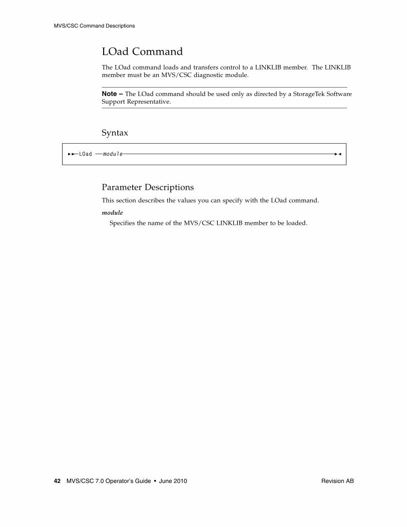
LOad CommandThe LOad command loads and transfers control to a LINKLIB member. The LINKLIB member must be an MVS/CSC diagnostic module.
Note – The LOad command should be used only as directed by a StorageTek Software Support Representative.
Syntax
Parameter DescriptionsThis section describes the values you can specify with the LOad command.
module
Specifies the name of the MVS/CSC LINKLIB member to be loaded.
LOad module

MVS/CSC Command Descriptions
Revision AB Chapter 3 Commands 43
LOG CommandThe LOG command turns on or off the logging of MVS/CSC events and the logging of communications between the MVS/CSC and the LCS. It can also be used to reset the event log.
Syntax
Parameter DescriptionsThis section describes the values you can specify with the LOG command.
YES
Specifies that logging of events is to start at the current location in the event-log data set.
NO
Specifies that logging of events is to stop.
RESET
Specifies that logging is to begin or continue after resetting to the start of the event-log data set.
Example of LOG RESET Command
In this example, logging is reset to begin or continue after resetting to the start of the event-log data set.
Messages are sent to the console where the command was issued. For example:
For event logging in a VM-based LCS configuration, you can print the event-log data set using the Event Log Report utility. Refer to the MVS/CSC System Programmer’s Guide for more information about the Event Log Report utility.
For event logging in a UNIX-based LCS configuration, you can view the event-log data set directly, without post-processing by the Event Log Report utility. See “Event Log Facility” on page 59 for more information.
CSC7 LOG RESET
SCS0624I MVS/CSC logging is reset
LOG YESNORESET

MVS/CSC Command Descriptions
44 MVS/CSC 7.0 Operator’s Guide • June 2010 Revision AB
MODify CommandThe MODify or F command varies LSMs either online or offline to all hosts.
Syntax
Parameter DescriptionsThis section describes the values you can specify with the MODify LSM command.
LSM
Indicates that one or more LSMs are to be varied online or offline to all hosts.
lsm-id or lsm-range or (lsm-list)
Identifies one or more LSMs to be varied online or offline to all hosts.
Use this parameter to specify a single LSMid, a range of LSMids, or a list of single and/or ranges of LSMids. If you specify a list, the elements in the list must be separated by commas or blanks, and the list must be enclosed within parentheses.
The format for an LSMid is AA:LL, where AA is the ACSid and LL is the LSM number. Hexadecimal values from 000 through 7EF are valid for the LSMid.
ONline
Specifies that the LSM(s) is to be varied online to all hosts.
This places the LSM(s) in automatic mode.
OFFline
Specifies that the LSM(s) is to be varied offline to all hosts.
Modifying an LSM offline stops any new automated cartridge handling operations from being initiated, while allowing current activity to terminate normally. When all active requests have been processed, the MVS/CSC issues a console message to inform the operator that the LSM is offline. An offline LSM is placed in manual mode; that is, the operator must enter the LSM and manually mount/dismount tapes as required. See “Manual Mode Operations” on page 18 for manual operation procedures.
FORCE
Specifies that the LSM(s) is to be varied offline immediately.
If you specify the FORCE option with the OFFline parameter, all outstanding requests to the LSM are purged, and an initial program load (IPL) process might need to be run on the LSM. FORCE is only valid with the OFFline parameter.
MODifyF
LSM lsm-idlsm-range
( lsm-list,
)
ONlineOFFline
FORCE

MVS/CSC Command Descriptions
Revision AB Chapter 3 Commands 45
Example of MODify Command
In this example, LSMs 00:02 and 00:03 are varied offline.
Example of F Command
In this example, LSM 00:02 is varied back online.
MOD LSM (00:02,00:03) OFFLINE
F LSM 00:02 ONLINE
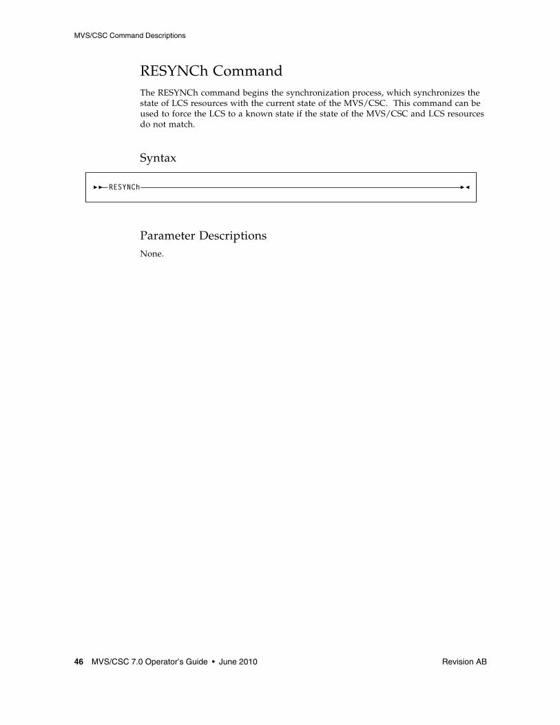
MVS/CSC Command Descriptions
46 MVS/CSC 7.0 Operator’s Guide • June 2010 Revision AB
RESYNCh CommandThe RESYNCh command begins the synchronization process, which synchronizes the state of LCS resources with the current state of the MVS/CSC. This command can be used to force the LCS to a known state if the state of the MVS/CSC and LCS resources do not match.
Syntax
Parameter DescriptionsNone.
RESYNCh

MVS/CSC Command Descriptions
Revision AB Chapter 3 Commands 47
Trace CommandThe Trace command enables or disables tracing of activities for selected MVS/CSC components. Output from the Trace command is directed to destination(s) specified on the TRACDest startup parameter. The TRACDest startup parameter must be set to CONsole and/or SYSlog for tracing of allocation data areas.
When the Trace command is specified without parameters, the trace status of each MVS/CSC component currently being traced is displayed.
Note – The Trace command should be used only for diagnostic purposes as directed by a StorageTek Software Support Representative.
Syntax
Parameter DescriptionsThis section describes the values you can specify with the Trace command.
compid-list
Specifies one or more component identifiers for which tracing is being started or stopped. If components are specified but OFF is not specified, tracing for the specified components is turned on. The component identifier can be any of the following:
AS Address Space Communication
AL Allocation Support
CF Configuration Manager
CS Communications Server
IT Initiation/Termination
MD Mount/Dismount
MH Message Handler
OC Operator Commands
RE Recovery
SV Services
UT Utilities
PG Programmatic Interface
Trace,compid-list
,OFF compid-list

MVS/CSC Command Descriptions
48 MVS/CSC 7.0 Operator’s Guide • June 2010 Revision AB
Example of Trace Command
In this example, the current trace status is displayed for each component being traced. Messages are sent to the console where the command was issued. For example:
Example of TRACE component Command
In this example, tracing of the Recovery component is turned on. Messages are sent to the console where the command was issued. For example:
CSC4 Trace
SCS0068I Current TRACE Status:Address Space Communication (AS) NOT TracedAllocation Support (AL) NOT TracedCommunications Server (CS) NOT TracedConfiguration Manager (CF) NOT TracedMessage Handler (MH) NOT TracedInitialization/Termination (IT) NOT TracedMount/Dismount (MD) NOT TracedOperator Commands (OC) NOT TracedRecovery (RE) NOT TracedUtilities (UT) NOT TracedServices (SV) NOT TracedProgrammatic Interface (PG) NOT Traced
CSC4 T RE
SCS0068I Current TRACE Status:Address Space Communication (AS) NOT TracedAllocation Support (AL) NOT TracedCommunications Server (CS) NOT TracedConfiguration Manager (CF) NOT TracedMessage Handler (MH) NOT TracedInitialization/Termination (IT) NOT TracedMount/Dismount (MD) NOT TracedOperator Commands (OC) NOT TracedRecovery (RE) TracedUtilities (UT) NOT TracedServices (SV) NOT TracedProgrammatic Interface (PG) NOT Traced

MVS/CSC Command Descriptions
Revision AB Chapter 3 Commands 49
Example of Trace OFF Command
In this example, tracing of all components and allocation data areas is turned off. Messages are sent to the console where the command was issued. For example:
CSC4 T OFF
SCS0068I Current TRACE Status:Address Space Communication (AS) NOT TracedAllocation Support (AL) NOT TracedCommunications Server (CS) NOT TracedConfiguration Manager (CF) NOT TracedMessage Handler (MH) NOT TracedInitialization/Termination (IT) NOT Traced Mount/Dismount (MD) NOT TracedOperator Commands (OC) NOT TracedRecovery (RE) NOT TracedUtilities (UT) NOT TracedServices (SV) NOT TracedProgrammatic Interface (PG) NOT Traced


Revision AB 51
CHAPTER
4
Operator Console Interface
OverviewThis chapter describes the operator console interface provided with the MVS/CSC.
MVS Operator Console InterfaceMVS/CSC commands are provided to display MVS/CSC information, alter startup parameter settings, start recovery processing, and enable diagnostic procedures. MVS commands are used to start, stop, cancel, or force the shutdown of MVS/CSC. These commands are issued from the MVS operator console.
For the VM-based LCS, the MVS operator console interface also supports VM/HSC commands as well as CLS commands. You can also receive and reply to HSC and CLS messages. Information in response messages is also displayed on the MVS operator console.
HSC, CLS, and SLK1 commands must be prefixed by identifiers that explicitly direct the commands to those software components. If a system qualifier is not entered for these commands, the commands are passed in the following order and executed by the appropriate system:
■ MVS/CSC■ CLS■ SCP (with prefix SLK)■ HSC
The MVS/CSC interprets commands as they are entered. It executes MVS/CSC commands and sends CLS and HSC command strings to the CLS. The CLS interprets each command, executes CLS commands, and forwards HSC commands to the HSC for execution.
The following sections list the HSC and CLS commands supported by the MVS operator console interface.
1. SLK identifies the VM/HSC Control Program

MVS Operator Console Interface
52 MVS/CSC 7.0 Operator’s Guide • June 2010 Revision AB
HSC CommandsThe MVS operator console interface supports the following VM/HSC commands:
■ CAPPREF■ CLEAN■ DISMOUNT■ DISPLAY■ DRAIN■ EJECT■ ENTER■ MODIFY■ MOUNT■ SENTER■ SET
Commands intended for the MVS/CSC are not prefixed with a component identifier. Commands intended for the HSC must be prefixed with (1) either the MVS/CSC command prefix character or the MVS/CSC subsystem name and (2) the HSC component identifier (HSC). In the following example, the first HSC Display command is prefixed with the MVS/CSC command prefix character (!). The second HSC Display command is prefixed with the MVS/CSC subsystem name (CSC0).
!HSC DISPLAY LSM 000 CSC0 HSC DISPLAY LSM 000
Because the commands contain the HSC component identifier, the MVS/CSC sends them first to the CLS for interpretation. The CLS, in turn, sends them to the HSC for execution.
The MVS/CSC command shown in the following example is interpreted and executed by the MVS/CSC:
CSC0 DISPLAY AVAIL
If the command were not an MVS/CSC command, it would be passed on to the CLS. If the command is a CLS command, it is processed by the CLS, otherwise CLS passes the command to the HSC for processing.
For HSC commands that are also MVS/CSC commands, the HSC component identifier must be specified in order to execute the command for the HSC. For example, the Display command is both an MVS/CSC and an HSC command. The first command in the following example shows the Display command for the MVS/CSC; it has no component identifier. The second command shows the Display command for the HSC; it specifies the HSC component identifier.
Refer to the VM/HSC Operator’s Guide for a complete list of HSC commands and descriptions of each command.
CSC0 DISPLAY .....CSC0 HSC DISPLAY .....

MVS Operator Console Interface
Revision AB Chapter 4 Operator Console Interface 53
CLS CommandsThe MVS operator console interface supports the following CLS commands:
■ Query■ Release■ Reserve■ Tell
Refer to the CLS Reference Manual for a complete list of CLS commands and descriptions of each command.
Operator ResponseSome HSC and CLS commands require a reply to the response returned by the HSC or CLS. The MVS/CSC coordinates the local response with the MVS system console so that replies should use the MVS reply identifier. The CLS and HSC systems may also send unsolicited messages to the MVS host system. Responses from unsolicited messages are routed through the CLS. ACSLS does not send unsolicited messages to the MVS/CSC.


Revision AB 55
CHAPTER
5
Software Diagnostic Tools and Recovery Procedures
OverviewThis chapter describes the following diagnostic facilities and recovery capabilities provided with MVS/CSC to help in diagnosing problems and monitoring activities:
■ Synchronization and system recovery processing
■ Availability and heartbeat message processing (VM-based LCS)
■ The Event Log facility, which records significant events
■ The Trace facility, which displays execution paths of MVS/CSC modules
■ Operator recovery procedures, which describe options for handling errors that require operator intervention
Synchronization and System Recovery ProcessingThe MVS/CSC provides synchronization and system recovery processing functions and early detection of failures through use of heartbeat logic, timers, information from the LCS system, and the ability of MVS/CSC software to recognize potential error conditions.

Synchronization and System Recovery Processing
56 MVS/CSC 7.0 Operator’s Guide • June 2010 Revision AB
Synchronization Recovery ProcessingRecovery is the automatic process of synchronizing resource states between the MVS/CSC and the LCS after a failure or outage. If the MVS/CSC terminates abnormally, it can be restarted using instructions provided in “Starting the MVS/CSC” on page 15. The MVS/CSC automatically attempts to recover resources at start time.
The MVS/CSC recovery processing functions are designed to minimize the impact of system failures on system operations. The recovery functions of the automated tape library cartridge system are designed to require minimum human intervention during recovery processing. The primary recovery responsibilities provided by MVS/CSC are to:
■ Recover system resources that were being used before a system failure. ■ Synchronize library resource states between the MVS/CSC and the LCS. ■ Avoid disturbing MVS jobs currently using library resources.
The MVS/CSC software detects internal software failures and unexpected LCS responses (for example, the LSM is offline or an LSM door is open). The MVS/CSC performs recovery operations to minimize the impact of MVS jobs currently using or waiting to use library transports and cartridges. It responds to failure conditions using error messages, operator intervention, process retries, waiting periods, diagnostic data capture, and MVS/CSC subsystem abends.
After re-establishing communications with the LCS, the MVS/CSC is responsible for resynchronizing with the LCS system. During recovery processing, the MVS/CSC issues messages to the LCS to determine the status of library resources. Based on the responses from the LCS, MVS/CSC synchronization processing adjusts the status of both LCS and MVS/CSC resources, so that the LCS and MVS/CSC systems contain the same information about current library transports and cartridges.

Synchronization and System Recovery Processing
Revision AB Chapter 5 Software Diagnostic Tools and Recovery Procedures 57
System Recovery ProcessingThe unavailability of the MVS/CSC, the LCS, or the library hardware can have a severe impact on the operation of the MVS host system. The MVS/CSC attempts to detect failures as quickly as possible in order to avoid impacting MVS jobs currently using or waiting to use library resources.
System Recovery for a UNIX-based or VM-based LCSWhen the MVS/CSC detects that a UNIX-based or VM-based LCS is not available, it stops sending library requests until the LCS has returned to normal operating mode. For mount and dismount requests for library transports, a WTOR message requesting intervention is issued to the MVS operator. If the LCS availability has been re-established, the operator should reply that the operation be retried. If the LCS is still unavailable after the operation is retried, the operator may want to cancel the job.
Note – See “Operator Recovery Procedures” on page 61 for information about operator recovery procedures.
Recovery ProceduresRecovery from system failures is accomplished using any of the following software processing:
■ Programmed recovery techniques (such as ESTAEs and FRRs)■ Recovery routines supplied by the MVS system■ Automatic restarting or reinitiating the systems■ System requests for operator intervention■ Messages sent to the LCS for status information■ Messages sent to the LCS to update status information

Availability and Heartbeat Message Processing (VM-based LCS)
58 MVS/CSC 7.0 Operator’s Guide • June 2010 Revision AB
Availability and Heartbeat Message Processing (VM-based LCS)The following sections describe recovery processing for the VM-based LCS.
Availability Message ProcessingThere may be times when the CLS does not respond to the MVS/CSC availability message sent during initialization. When this occurs, the MVS/CSC must wait for the availability message exchange to be completed before any processing can occur. After a specified amount of time without a response from the CLS system, the MVS/CSC sends a message to the MVS console requesting operator assistance in resolving the situation. For information about responding to system generated messages, refer to the publication ELS Messages and Codes.
Heartbeat LogicPeriodically, the CLS system transmits a heartbeat message to the MVS/CSC. The amount of time between heartbeat messages is transmitted to the MVS/CSC at MVS/CSC start-up time. The purpose of the heartbeat message is to ensure that the MVS/CSC system is still functioning and to inform the MVS/CSC that the CLS is still functioning.
The CLS system sends the heartbeat message under the following conditions:
■ If the CLS has not sent or received a message from the MVS/CSC after a specified amount of time. The interval is specified in the CLS using the CLS Configuration Management (CLSCM) program. The MVS/CSC gets the message from the CLS. Each client system can define a different interval.
■ If there is no response to the heartbeat message after a specified amount of time (the CLS system sends warning messages to the VM and CLS operators alerting them of a possible failure condition).
The CLS holds all outgoing and incoming messages in a queue until a response to the heartbeat message is received from the MVS/CSC. Failure conditions could include the following:
■ Communications link failure■ Immediate MVS/CSC shutdown■ Abnormal MVS/CSC termination■ MVS system failure■ Communications failure
The MVS/CSC also includes a mechanism for detecting lack of message traffic from the CLS system. The MVS/CSC timer is set to twice the value of the CLS heartbeat interval. If the timer expires, the CLS is designated as unavailable. Once the CLS is made unavailable, the MVS/CSC system sends a message to the MVS console, notifying the operator that the CLS is not available. Once the MVS/CSC detects that the CLS is not available, it begins recovery processing.

Event Log Facility
Revision AB Chapter 5 Software Diagnostic Tools and Recovery Procedures 59
Event Log FacilityThe MVS/CSC Event Log facility records starts and stops of the MVS/CSC, all message traffic between the MVS/CSC and server, and other miscellaneous events. This information can be used in problem determination for the LCS or MVS/CSC, and also for general reporting of activities.
The LOG startup parameter, which is specified in the startup parameter file, is used to start, stop, or reset event logging. Event logging can be started or stopped using the LOG operator command. If the event-log data set was not allocated at MVS/CSC initialization time and you want to start event logging, you must first reinitialize the MVS/CSC and specify the SCSLOG DD name in the startup procedure and set the LOG startup parameter to YES or RESET. Refer to the MVS/CSC Configuration Guide for more information about the LOG startup parameter. See “LOG Command” on page 43 for information about the LOG operator command.
For UNIX-based configurations, the MVS/CSC writes a summary report about LCS requests and responses to the event-log data set in text format. This allows you to view the event-log data set directly, without post-processing by the Event Log Report utility.
The following example shows how requests and responses are written to the event-log data set for UNIX-based LCS configurations.
The first 25 bytes contain the log record type and the timestamp; seq_nmbr is the sequence number, which matches the requests and responses, and rc is the return status from the status of network requests and/or the LCS. The information that follows the return codes represents the portions of the LCS requests or responses that are related to the end-user requests.
Note – To assist in diagnosis and resolution of a problem, the event log should be included with other documentation when reporting a system failure to StorageTek Software Support.
SL0B552 05261995185730480 seq_nmbr=33 QUERy_VOLUME rc=SUCCESS vol=MVC055 count=1SL0B562 05261995185733320 seq_nmbr=33 ACK rc=SUCCESSSL0B562 05261995185734470 seq_nmbr=33 FINAL rc=SUCCESS vol=MVC055 vol_status=VOLUME_HOME loc=2.0.3.0

Trace Facility
60 MVS/CSC 7.0 Operator’s Guide • June 2010 Revision AB
Trace FacilityThe MVS/CSC Trace facility helps in diagnosing problems. It records the logic path being executed through each module in each MVS/CSC component for which tracing is enabled. While debugging a specific problem, the specific components to be traced can be specified. The MVS/CSC issues the appropriate Write-To-Operator (WTO) calls to trace the execution of the designated modules.
Tracing is enabled using the Trace startup parameter or the Trace operator command. Refer to the MVS/CSC Configuration Guide for information about the Trace startup parameter. See “Trace Command” on page 47 for information about the Trace operator command.
Note – The Trace facility is usually used at the request of StorageTek Software Support to assist in diagnosis and resolution of a problem.
Normal operation of the MVS/CSC is performed with tracing disabled for all MVS/CSC components.
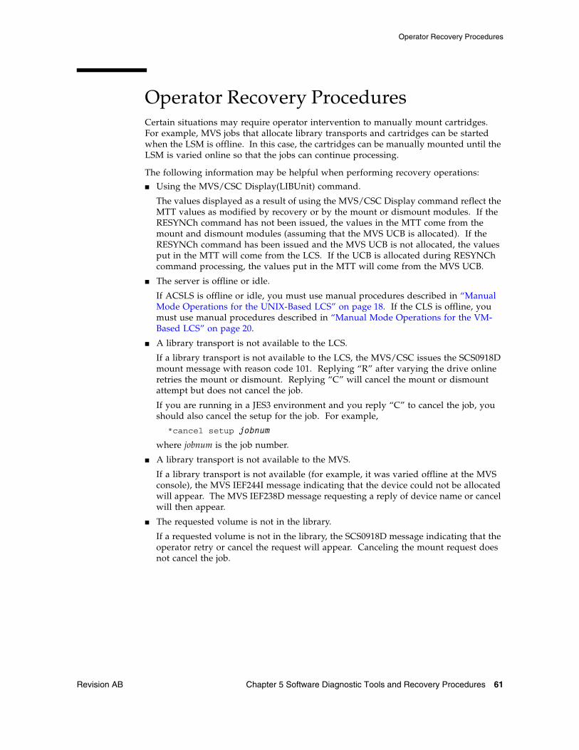
Operator Recovery Procedures
Revision AB Chapter 5 Software Diagnostic Tools and Recovery Procedures 61
Operator Recovery ProceduresCertain situations may require operator intervention to manually mount cartridges. For example, MVS jobs that allocate library transports and cartridges can be started when the LSM is offline. In this case, the cartridges can be manually mounted until the LSM is varied online so that the jobs can continue processing.
The following information may be helpful when performing recovery operations:
■ Using the MVS/CSC Display(LIBUnit) command.
The values displayed as a result of using the MVS/CSC Display command reflect the MTT values as modified by recovery or by the mount or dismount modules. If the RESYNCh command has not been issued, the values in the MTT come from the mount and dismount modules (assuming that the MVS UCB is allocated). If the RESYNCh command has been issued and the MVS UCB is not allocated, the values put in the MTT will come from the LCS. If the UCB is allocated during RESYNCh command processing, the values put in the MTT will come from the MVS UCB.
■ The server is offline or idle.
If ACSLS is offline or idle, you must use manual procedures described in “Manual Mode Operations for the UNIX-Based LCS” on page 18. If the CLS is offline, you must use manual procedures described in “Manual Mode Operations for the VM-Based LCS” on page 20.
■ A library transport is not available to the LCS.
If a library transport is not available to the LCS, the MVS/CSC issues the SCS0918D mount message with reason code 101. Replying “R” after varying the drive online retries the mount or dismount. Replying “C” will cancel the mount or dismount attempt but does not cancel the job.
If you are running in a JES3 environment and you reply “C” to cancel the job, you should also cancel the setup for the job. For example,
*cancel setup jobnum
where jobnum is the job number.
■ A library transport is not available to the MVS.
If a library transport is not available (for example, it was varied offline at the MVS console), the MVS IEF244I message indicating that the device could not be allocated will appear. The MVS IEF238D message requesting a reply of device name or cancel will then appear.
■ The requested volume is not in the library.
If a requested volume is not in the library, the SCS0918D message indicating that the operator retry or cancel the request will appear. Canceling the mount request does not cancel the job.
Operator Recovery Procedures
62 MVS/CSC 7.0 Operator’s Guide • June 2010 Revision AB
■ The network is not available.
If the LCS is available (functioning) but the network is not available, the volumes may be loaded from the ACS System Administrator’s (ACSSA) console without entering the LSM. The System Administrator should be told of the intended volume and transport because the MVS transport identification must be transferred to the appropriate LCS syntax. If the network becomes available before the REQTime value expires, the MVS/CSC RESYNCh command should be entered. If the REQTime value has expired, the MVS/CSC Recovery component will be in resynchronization. Refer to the MVS/CSC Configuration Guide for more information about the REQTime startup parameter.
■ The network is busy.
If the network is overloaded for a time in seconds equal to the product of RETTime multiplied by RETCount, the MVS/CSC will fail the request. For mount and dismount requests, messages will be left on the MVS operator console. They must be answered one-by-one in order to stop the MVS/CSC. MVS/CSC will not terminate normally if outstanding mount and dismount messages exist. Otherwise, the mounts and dismounts will complete without intervention if the operator does not respond to the messages but waits until the network is not overloaded. Refer to the MVS/CSC Configuration Guide for more information about the RETTime and RETCount startup parameters.
■ TCP/IP communication software is terminated while the MVS/CSC is still active.
If TCP/IP software terminates while the MVS/CSC is still active, the MVS/CSC does not recover. You must stop and restart the MVS/CSC. To avoid this problem, always stop the MVS/CSC using the MVS Stop (or Cancel) command before terminating TCP/IP software.
Note – CLS repeatedly attempts to re-establish the TCP/IP software connection. This continues until a connection is established, or the MVS/CSC is shut down.

Revision AB 63
APPENDIX
A
Gathering Diagnostic Materials
OverviewDuring problem resolution, Software Support may request that you provide specific diagnostic material. While printed format may be accepted, machine readable data (on magnetic tape) is preferred. For small amounts of data, Software Support may request that you FAX the data. Doing this may significantly reduce the time needed to resolve your problem.
MVS Diagnostic MaterialsThe following MVS/CSC diagnostic materials may be requested by Software Support:
■ Details of circumstances■ MVS SYSLOG■ SCSLOG data set■ SCSTRACE data set■ SYSxDUMP and SYS1.DUMPnn data sets■ Event Log Report (VM-based LCS)■ Event log data set (UNIX-based LCS)■ EREP records (software)■ MVS/CSC startup parameter file■ MVS/CSC startup procedure (cataloged procedure)■ MVSCP/IOCP definition or HCD
Tape Format
64 MVS/CSC 7.0 Operator’s Guide • June 2010 Revision AB
Tape FormatIf Software Support requests a tape containing your diagnostic materials, copy the requested files to tape using standard utility programs.
Include a description of the tape contents, including any information necessary for Software Support to retrieve the files from the tape (i.e., tape volume serial number and label attributes, number of files, file names and attributes, etc.).

Revision AB 65
APPENDIX
B
List of Abbreviations
abend Abnormal end of task
ACS Automated Cartridge System
APPC Advanced-Program-to-Program Communications
CAP Cartridge access port
CDS Control data set
CLS Common Library Services
CLSCOMM CLS Communications
CLSCM CLS Configuration Management
CLSLP CLS logical port
CLSM CLS Manager
CLSOC CLS operator console
CMS Conversational monitor system
CP Control program
CPA Control Path Adaptor
CSA Common service area
CSC Client System Component
CSSC Customer Service Support Center
DASD Direct access storage device
DFSMS Data Facility Storage Management Subsystem
DMS/OS DASD Management System/Operating System
EC Engineering change
EDL Eligible Device List
ESC European Support Center
HCD Hardware Configuration Definition
HSC Host Software Component
IBM International Business Machines Corporation
ICRC Improved Cartridge Recording Capacity
ID Identifier or identification

66 MVS/CSC 7.0 Operator’s Guide • June 2010 Revision AB
IJS Intermediate Job Summary table
IML Initial microcode load
I/O Input/output
IOCP I/O Configuration Program
IP Internet Protocol
IPL Initial program load
ISMF Interactive Storage Management Facility
JCL Job control language
JES Job entry subsystem
JST Job Summary Table
LAN Local area network
LCU Library Control Unit
LMU Library Management Unit
LP Logical port
LU Logical unit
LSM Library Storage Module
MB Megabyte
MIM Multi-image Manager
MVS Multiple virtual storage
MVS/ESA Multiple Virtual Storage/Enterprise Systems Architecture
MVS/SP Multiple Virtual Storage/System Product
PCR Product change request
PGMI Programmatic interface
PIB Product Information Bulletin
PN Part number
PROP Programmable operator facility
PTF Program temporary fix
PUT Program update tape
PVM VM/Pass-Through Facility
RACF Resource access control facility
RPC Remote procedure call
SAF System Authorization Facility
SER Software Enhancement Request
SCP System control program
SLK Refers to the SCP
SMC Storage Management Component
SMP/E System Modification Program Extended
SMS Storage Management Subsystem

Revision AB Appendix B List of Abbreviations 67
SNA Systems Network Architecture
SP System Product
SSR System Support Representative
Sysplex System complex
TCP/IP Transmission Control Protocol/Internet Protocol
TLMS Tape library management system
TMI Tape management interface
TMS Tape management system
VLR Volume location record
VM Virtual machine
VOLSER Volume serial number
VSM Virtual Storage Manager
VTAM Virtual Telecommunications Access Method
VTCS Virtual Tape Control System
VTSS Virtual Tape Storage Subsystem
WSC World Wide Support Center
WTO Write-to-operator
WTOR Write-to-operator with reply
XCF Cross-system coupling facility


Revision AB 69
Glossary
This glossary defines terms and abbreviations used in this publication.
AAbnormal end of task (abend) A software or hardware problem that terminates a computer processing task.
ACS-id A method used in the LIBGEN process to identify ACSs by using hexadecimal digits, 00 to nn.
ACS See Automated Cartridge System.
ACS library A library is composed of one or more Automated Cartridge Systems (ACSs), attached cartridge drives, and cartridges residing in the ACSs.
address Coded representation of hardware id, or the destination or origination of data.
allocation The assignment of resources to a specific task.
asynchronous transmission Character-oriented data transmission (as distinct from IBM’s block-mode transmission).
Automated Cartridge System (ACS) A fully-automated, cartridge storage and retrieval library subsystem consisting of one or more Library Storage Modules (LSMs) connected by pass-thru ports.
Automated Cartridge System Library Software (ACSLS) The library control software, which runs in the UNIX®-based Library Control System.
automatic mode A relationship between an LSM and all attached hosts. LSMs operating in automatic mode handle cartridges without operator intervention. This is the normal operating mode of an LSM that has been modified online. The opposite situation is “manual mode.” See manual mode.

70 MVS/CSC 7.0 Operator’s Guide • June 2010 Revision AB
Bbar code A code consisting of a series of bars of varying widths. This code appears on the external label attached to the spine of a cartridge and is equivalent to the volume serial number (volser). This code is read by the robot’s machine vision system.
BISYNC Binary Synchronous Communications. An early low-level protocol developed by IBM and used to transmit data on a synchronous communications link. It is a form of data transmission in which synchronization of characters is controlled by timing signals generated at the sending and receiving stations.
CCAPid A CAPid uniquely defines the location of a CAP by the LSM on which it resides. A CAPid is of the form “AAL” where “AA” is the acs-id and “L” is the LSM number.
cartridge The plastic housing around the tape. It is approximately 4 inches (100 mm) by 5 inches (125 mm) by 1 inch (25 mm). The tape is threaded automatically when loaded in a transport. A plastic leader block is attached to the tape for automatic threading. The spine of the cartridge contains an OCR/Bar Code label listing the VOLSER (tape volume identifier).
Cartridge Access Port (CAP) An assembly that allows several cartridges to be inserted into or ejected from an LSM without human entry into the LSM.
cartridge drive (CD) A hardware device containing two or four cartridge transports and associated power and pneumatic supplies.
cartridge tape I/O driver Operating system software that issues commands (for example, read, write, and rewind) to cartridge subsystems. It is the software focal point for attaching a particular type of control unit. (An example is Oracle’s StorageTek CARTLIB product.)
cartridge transport See transport.
CDS See Control Data Set.
cell A receptacle in the LSM in which a single cartridge is stored.
CGI Common Gateway Interface
channel A device that connects the host and main storage with the input and output devices’ control units. A full-duplex channel has two paths (that is, 2 wires, or one wire with signals at two frequencies). A half-duplex channel requires that one port receives while the other transmits.
channel-to-channel (CTC) Refers to the communication (transfer of data) between programs on opposite sides of a channel-to-channel adapter.(I)
client The ultimate user of the ACS services as provided by the Library Control System.
client link The communications link between the LCS and a client.

Revision AB Glossary 71
client-server A model of interaction in a distributed system in which a program at one site serves a request to a program at another site and awaits a response. The requesting program is called a client; the program satisfying the request is called a server.
client system The system to which the LCS provides an interface to a StorageTek Automated Cartridge System.
Client System Component (CSC) Software that provides an interface between the Client Computing System’s operating system and the StorageTek Library Control System (LCS).
coaxial cable A transmission medium used in data transmissions for networks using synchronous communications, as opposed to twisted-pair, the primary medium for asynchronous RS-232 communications.
complex A system composed of other systems, specifically the ACS server system and the client system.
connected mode A relationship between a host and an ACS. In this mode, the host and an ACS are capable of communicating (in the sense that at least one station to this ACS is online).
connection number The unique identifier on the server for a communications path. The number is assigned by TCP/IP to identify the unique connection between the server node and a specific port on the server, and the client node and a specific port on the client. The connection number exists only as long as the connection exists.
console The primary I/O device to control a session on a system.
control data set (CDS) The data set used by the host software to control the functions of the automated library. Also called a library database.
Control Path Adaptor (CPA) A Bus-Tech, Inc. hardware device that allows communications between a host processor’s block multiplexer channel and a local area network.
Control Unit (CU) A microprocessor-based unit situated locally between a channel and an I/O device. It translates channel commands into device commands and sends device status to the channel.
coupling facility A special logical partition that provides high-speed caching, list processing, and locking functions in a sysplex.(I)
coupling facility channel A high bandwidth fiber optic channel that provides the high-speed connectivity required for data sharing between a coupling facility and the central processor complexes directly attached to it.(I)
CTC Channel-to-channel.
Data Path Adapter A hardware device which translates from a client computing system’s data protocol to the data protocol of the StorageTek Control Unit or IMU. An example is DEC’s TC44-AA/BA STI-to-4400 ACS Interconnect.

72 MVS/CSC 7.0 Operator’s Guide • June 2010 Revision AB
Ddata set A set of records treated as a unit.
data sharing The ability of concurrent subsystems or application programs to directly access and change the same data while maintaining data integrity.(I)
device number A four-digit hexadecimal number that uniquely identifies a device attached to a processor.
device preferencing The process of preferring one 36-track transport type over another 36-track transport type.
device separation See drive exclusion.
direct access storage device (DASD) IBM’s term for a disk drive storage device.
directed allocation See drive prioritization.
disconnected mode A relationship between a host and an ACS. In this mode, the host and the ACS are not capable of communicating (there are no online stations to this ACS).
dotted-decimal notation The syntactic representation of a 32-bit integer that consists of four 8-bit numbers written in base ten with periods (dots) separating them. In TCP/IP descriptions, dotted-decimal notation is used for Internet addresses.
drive exclusion (previously referred to as device separation) refers to the Storage Management Component (SMC) function of excluding drives for an allocation request based on SMC exclusion criteria.
drive panel An LSM wall containing tape transports. The drive panel for a T9840 transport can contain either 10 or 20 transports. The drive panel for a non-T9840 transport can contain a maximum of 4 transports.
drive prioritization (previously referred to as directed allocation) refers to the Storage Management Component (SMC) function of influencing selection of a particular drive based on allocation criteria, including volume location.
Dual LMU A hardware/microcode feature that provides a redundant LMU capability.
dump A printed representation of the contents of main storage at time t. This representation is used for debugging purposes.

Revision AB Glossary 73
EECART Enhanced Capacity Cartridge.
Enhanced Capacity Cartridge A cartridge that has a length of 1100 feet and can be used only on 36-track transports (i.e., 4490, 9490, and 9490EE).
Enterprise Systems Connection (ESCON) A set of products and services that provides a dynamically connected environment using optical cables as a transmission medium.(I)
error codes (EC) Numeric codes displayed by messages indicating the type of problem that caused an error.
error recovery procedures (ERP) Procedures designed to help isolate and, where possible, to recover from errors in equipment.
ESCON Enterprise Systems Connection.
Ethernet One LAN architecture using a bus topology that allows a variety of computers to be connected to a common shielded coaxial spine. The Ethernet architecture is similar to the IEEE 802.3 standard.
Ffile A set of related records treated as a unit.
File Transfer Protocol (FTP) A TCP/IP command that provides a way to transfer files between machines connected through TCP/IP.
foreign socket One of two end-points in a TCP/IP connection-oriented protocol. Specifies the address of a foreign host that can connect to the server.
GGB 1,073,741,834 bytes of storage

74 MVS/CSC 7.0 Operator’s Guide • June 2010 Revision AB
Hhandshake A flow-of-control signal sent by one process to another.
helical cartridge A high capacity, helical scan cartridge that can hold up to 50GB of uncompressed data. This cartridge can be used only on RedWood (SD-3) transports.
host computer A computer that controls a network of computers.
Host Software Component (HSC) Software running on the Library Control System processor that controls the functions of the ACS.
Host Software Component utilities Utilities provided by the VM/HSC that can be executed from the HSCUTIL virtual machine. See client-initiated utilities.
HSC See Host Software Component.
HTTP Hypertext Transfer Protocol.
IIEEE 802.3 A standard produced by the IEEE and accepted worldwide for local area networks using CSMA/CD (Carrier Sense Multiple Access with Collision Detection).
ICRC Improved Cartridge Recording Capacity. A compression and compaction feature that increases the amount of data that can be stored on a 1/2-inch cartridge.
initial program load (IPL) A process that activates a machine reset.
Interactive Storage Management Facility A series of applications for defining DFSMS/MVS storage groups and classes.
Internet A collection of networks using TCP/IP that functions as a virtual network.
Internet address The numbering system used to specify a network or host on that network for TCP/IP communications. Standard Internet address notation is dotted-decimal format.
Internet Protocol (IP) Formal description of messages and rules two networks use to exchange messages.
ISMF Interactive Storage Management Facility.

Revision AB Glossary 75
Jjob control language (JCL) A problem oriented language designed to describe a job’s processing requirements to an operating system.
JES Job entry subsystem.(I)
JES2 An MVS subsystem that receives jobs into the system, converts them to internal format, selects them for execution, processes their output, and purges them from the system. In an installation with more than one processor, each JES2 processor independently controls its job input, scheduling, and output processing. See also JES3.(I)
JES3 An MVS subsystem that receives jobs into the system, converts them to internal format, selects them for execution, processes their output, and purges them from the system. In complexes that have several loosely coupled processing units, the JES3 program manages processors so that the global processor exercises centralized control over the local processors and distributes jobs to them via a common job queue. See also JES2.(I)
LLAN See local area network.
LCS See Library Control System.
LCS processor console The Library Control System processor console is used to control the VM operating system (for the VM-based LCS).
LCU See Library Control Unit.
LIBGEN The process of defining the configuration of a library to the VM/HSC.
library See TapePlex.
library cartridge transport See transport.
library complex A library complex consists of one HSC Control Data Set (CDS) and may contain up to 256 Automatic Cartridge Systems (ACSs), each of which may contain up to 24 Library Storage Modules (LSMs).
library control component Software that controls the mounting and dismounting of cartridges in an ACS.
library control platform The hardware and software that provides the proper environment for the Library Control System.
library control processor Properly configured computer hardware that supports the operation of the Library Control System.
Library Control Software A library control component, the client system interface, and library utilities.
Library Control System (LCS) The library control platform and the Library Control Software.

76 MVS/CSC 7.0 Operator’s Guide • June 2010 Revision AB
Library Control Unit (LCU) The portion of an LSM that controls the movements of the robot.
library database A file or data set containing information about the location and status of the removable media volumes, such as cell location, scratch status. Also called a control data set (CDS).
library drive A cartridge drive in the ACS, as distinct from a stand-alone cartridge drive.
Library Management Unit (LMU) A hardware and software product that coordinates the activities of one or more LSMs/LCUs.
library mode The operation of a 4480 Cartridge Subsystem as part of a 4400 Automated Cartridge System, as opposed to manual mode, in which the operator inserts cartridges into the transports. See manual mode.
Library Storage Module (LSM) The standard LSM (4410) a twelve-sided structure with storage space for up to around 6000 cartridges. It also contains a free-standing, vision-assisted robot that moves the cartridges between their storage cells and attached transports. See also PowderHorn, SL3000, SL8500, and WolfCreek.
LMU See Library Management Unit.
local area network (LAN) A network in a small (local) geographic area.
local port The designation of a given application or process among many that are available for a TCP/IP-capable host processor.
local socket The address combination of a TCP/IP-capable host’s network address and a specific port for an application process.
logical port (LP) CLS software that interfaces with the client system. The CLSLP is one of the software components used to pass data between the client system and the VM/HSC.
LP See logical port.
LSM See Library Storage Module.
LSM-id An LSM-id is composed of the ACS-id joined to (concatenated with) the LSM number.
LSM number A method used to identify an LSM. An LSM number is the result of defining the SLIACS macro LSM parameter during a LIBGEN. The first LSM listed in this parameter acquires the LSM number of 00 (hexadecimal) the second LSM listed acquires a number of 01, and so forth, until all LSMs are identified (up to a maximum of 24 or hexadecimal 17).

Revision AB Glossary 77
Mmanual mode Operation of a cartridge drive apart from an ACS. See library mode.
master LMU The LMU currently controlling the functional work of the ACS in a dual LMU configuration.
mixed configuration A configuration that contains different types of cartridge drives in both manual and library modes.
modem A device that enables digital data to be transmitted over an analog transmission facility.
multi-client The environment where more than one (homogenous or heterogeneous) client system is connected to one LCS.
MVS system console The MVS/CSC provides an operator interface through the MVS system console.
OOCR label Optical character recognition label. An external label attached to the spine of a cartridge that is both human and machine readable.
operator console In this publication, the operator console refers to the MVS client system console.
operating system (OS) Software that controls the execution of programs that facilitate overall system operation.

78 MVS/CSC 7.0 Operator’s Guide • June 2010 Revision AB
PPass-thru Port (PTP) A mechanism that allows a cartridge to be passed from one LSM to another in a multiple LSM ACS.
physical port The communications hardware required to support a server/client link.
physical volume A physically bound unit of data file media. See cartridge.
pool A collection of tape cartridges having one or more similar features or attributes, such as a pool of scratch tapes.
PowderHorn (9310) The high-performance version of the standard LSM.
pre-configured package A storage server package including all hardware, software, and configuration parameter settings delivered by the vendor.
product change request (PCR) A request for enhancement to a product. Normally, this request comes from a client, but may come from Oracle.
program temporary fix (PTF) A software release designed to remedy one or a series of defects.
program update tape (PUT) One or more tapes containing updates to, or new versions of, the MVS/CSC system software.
protocol A formal description of message formats and the rules two or more machines must follow to exchange these messages.
RResource Access Control Facility (RACF) An IBM-licensed program that provides access control by identifying and verifying the users to the system.
recovery Automatic or manual procedures to resolve problems in the server system.
reel-id Identifier of a specific tape volume. Equivalent to volume serial number (VOLSER).
request Term used to refer to commands issued to the 4400 ACS to perform a tape-related function.
Revision AB Glossary 79
Sscratch tape A tape that is available to any user because it is not owned.
scratch tape subpool A defined subset of all scratch tapes. Subpools are composed of one or more ranges of volsers with similar physical characteristics (type of volume—reel or cartridge, reel size, length, physical location, and so on). Some installations may also subdivide their scratch pools by other characteristics such as label type.
SD-3 Oracle’s StorageTek helical cartridge transport. Also known as RedWood.
server A library control system such as HSC. In SMC a server is represented by a named SERVER path to a named TAPEPLEX. While the StorageTek HTTP server software component is required as the middle ware on the remote host, the server, as far as SMC is concerned is the library control system operating on the remote host.
socket A unique address on a network plus a node address plus the id of one specific application on a specific network. An abstraction used by TCP/IP.
standard capacity cartridge A cartridge that can be used on any longitudinal transport (i.e., 4480, 4490, 9490, or 9490EE).
standby The status of a station that has been varied online but is connected to the standby LMU of a dual LMU ACS.
standby LMU The redundant LMU in a dual LMU configuration that is ready to take over in case of a Master LMU failure or when the operator issues a SWITCH command.
station A hardware path between the host computer and an LMU over which the VM/HSC and LMU send control information.
Storage Management Component (SMC) Software interface between IBM’s z/OS operating system and StorageTek real and virtual tape hardware. SMC performs the allocation processing, message handling, and SMS processing for the ELS solution.
storage server A set of hardware and software products designed to enable heterogeneous computer systems to use automated tape cartridge library services.
switchover The assumption of master LMU function by the standby LMU.
synchronous See BISYNC.
synchronous LAN Local area network built on synchronous communications.
Systems Network Architecture (SNA) A description of the logical structure, formats, protocols, and operational sequences for transmitting information units through and controlling the configuration and operation of networks.

80 MVS/CSC 7.0 Operator’s Guide • June 2010 Revision AB
Ttape drive A tape processing device consisting of up to four transports in a cabinet. A drive can refer to an individual transport.
tape library management system (TLMS) TLMS, as used in this publication, refers to any tape library management system, not to CA-1.
TapePlex (formerly “library”), a single StorageTek hardware configuration, normally represented by a single HSC Control Data Set (CDS). A TapePlex may contain multiple Automated Cartridge Systems (ACSs) and Virtual Tape Storage Subsystems (VTSSs).
TCP/IP Transmission Control Protocol/Internet Protocol.
trace event type Types of event traced through the system when tracing is enabled.
trace file A file that contains information useful for debugging the system.
transaction A specific set of input that triggers the execution of a specific process.
Transmission Control Protocol (TCP) An inter-network standard protocol that provides a full-duplex stream service.
transport An electro-mechanical device used to thread, position, and read or write from a tape.
UUCB Unit Control Block.
userid Sometimes referred to as the VM userid, the userid is the name that identifies a specific “virtual machine” user or client.
utility Program that performs a function ancillary to the chief function(s) of a computer system.

Revision AB Glossary 81
Vvirtual machine (VM) A functional simulation of a computer and its associated devices. Each virtual machine is controlled by a suitable operating system.
virtual storage A feature of the OS where main storage requirements are allocated by segments (or pages) as needed by programs, thus creating the apparent existence of unlimited or virtual storage.
Virtual Storage Manager (VSM) A storage solution that virtualizes volumes and transports in a VTSS buffer in order to improve media and transport use.
Virtual Tape Control System (VTCS) The primary host code for the Virtual Storage Manager (VSM) solution. This code operates in a separate address space, but communicates closely with HSC.
Virtual Tape Storage Subsystem (VTSS) The DASD buffer containing virtual volumes (VTVs) and virtual drives (VTDs). The VTSS is a StorageTek RAID 6 hardware device with microcode that enables transport emulation. The RAID device can read and write “tape” data from/to disk, and can read and write the data from/to a real tape drive (RTD).
Virtual Telecommunications Access Method (VTAM) IBM host-resident communications software that serves as a common interface for communications.
VM See virtual machine.
VM/SP or VM/XA A proprietary operating system of IBM corporation that consists mainly of two major components, CP and CMS.
volume A tape cartridge (data carrier) that is mounted or dismounted as a unit.
volume serial number (VOLSER) An identifier of a physical volume.
WWolfCreek (9360) The high-performance LSM with a smaller capacity than the standard LSM.

82 MVS/CSC 7.0 Operator’s Guide • June 2010 Revision AB
ZZCART An extended-enhanced cartridge that uses a thinner media to provide twice the capacity of the enhanced capacity (ECART) cartridge. This cartridge has a length of 2200 feet and can be used only on TimberLine 9490EE 36-track transports.
Numerics802.3 See IEEE 802.3.
3270 IBM synchronous, block-mode, half-duplex terminals preferred for use with IBM 370 and related types of machine.
3270 protocol A telecommunications protocol that supports networks of 327x CRTs on IBM mainframes.
3274 Terminal control unit used on the ACS for processor-to-LMU communications.
3480 IBM’s 18-track half-inch cartridge tape drive model.
3490 IBM’s 36-track half-inch cartridge tape drive model.
3590 IBM’s newest cartridge tape drive model that supports 128-track recording technique.
4400 Automated Cartridge System (ACS) A fully automated, cartridge-based, 18-track storage and retrieval library. A 4400 ACS consists of 1 to 256 LMUs with each LMU connected to from 1 to 24 LSMs.
4410 The standard Library Storage Module (LSM).
4411 Library Control Unit (LCU).
4480 The StorageTek 18-track 1/2-inch cartridge transport.
4480 Cartridge Subsystem The StorageTek 4480 Cartridge Subsystem consists of a control unit (CU) plus cartridge drives (CDs).
4490 The StorageTek 36-track long-tape cartridge transport with ESCON support. Also known as Silverton.
4780 Same as a 4480, but is used for attachment to certain non-IBM computers.
8380 StorageTek DASD system.
9310 The PowderHorn, a high-performance version of the standard LSM (4410)
9360 The WolfCreek, a high-performance LSM with a smaller capacity than the standard LSM (4410).
9490 The StorageTek 36-track cartridge transport. Also known as TimberLine.
9490EE The StorageTek 36-track cartridge transport. Also known as TimberLine EE.
Revision AB Glossary 83
9740 A small, four-sided StorageTek library that supports large-style cartridge transports. This library can be configured to contain either 326 cartridges or 494 cartridges.
SL3000 The StorageTek high performance library scalable from 200 to 3,000 cartridge slots.
SL8500 The StorageTek high performance library scalable from 29 terabytes to 70 petabytes with up to 70,000 tape slots.
T9840A The StorageTek access-centric cartridge transport capable of reading and writing 9840A cartridges.
T9840B The StorageTek access-centric cartridge transport capable of reading and writing T9840B cartridges.
T9840C The StorageTek access-centric cartridge transport capable of reading and writing T9840C cartridges.
T9840DThe StorageTek access-centric cartridge transport capable of reading and writing T9840D cartridges.
T9940A The StorageTek capacity-centric cartridge transport capable of reading and writing 60GB T9940A cartridges.
T9940B The StorageTek capacity-centric cartridge transport capable of reading and writing 200GB T9940B cartridges.
T10000 The StorageTek high-capacity cartridge transport capable of reading and writing 120GB or 500GB T10000 cartridges.
T10000B The StorageTek high-capacity cartridge transport capable of reading and writing 240GB or 1TB T10000 cartridges.


Revision AB 85
Index
AALOCTIME startup parameter, changing values
for, 32ALTER command, 32automatic mode, LSM, 21
Bbasic functions, MVS/CSC, 2
CCANCEL command (MVS), 16cartridge
dismount processing, 22commands
MVS/CSC operator, 29Common Library Services (CLS), 6
command format, 31commands, specifying component identifier, 51MVS/CSC availability message, 58operator response to CLS commands, 53
communicationslogging with LOG command, 43
communications methodsoverview, 9
contacting Oracle StorageTek Support, xiiconventions
control statements, xviitypographic, xiii
customer-initiated maintenance (CIM), xii
DData Facility Hierarchical Storage Manager
(DFHSM), 7debugging problems, 60device preferencing, 12devices, mixed, 12diagnosing problems with Trace facility, 60diagnostics
displaying MVS/CSC control block and storage, 40
dismount processing for robot-mounted cartridges, 22
displaying LSM status, 21drive exclusion, 12
Eenvironment
MVS/CSC, 2event log
resetting with LOG command, 43Event Log facility
description, 59
FF (modify) command, 44Fault Analyzer for z/OS, interaction with
MVS/CSC, 8FORCE command (MVS), 16
Hheartbeat logic, 58Host Software Component (HSC)
command format, 31commands
DISPLAY LSM, 21specifying component identifier, 51
description, 6operator response to HSC commands, 53
Iinterfaces
MVS operator console, 13
LLibrary Control System (LCS)
software products, 5UNIX-based, 6VM-based, 6
Library Storage Module (LSM)automatic mode, 21DISPLAY LSM command, 21

86 MVS/CSC 7.0 Operator’s Guide • June 2010 Revision AB
manual-mode procedures, 21placing in manual mode, 22returning to automatic mode, 27verifying offline, 22
LIST command, 40LOAD command, 42LOG command, 43logging of MVS/CSC, 43LSM, varying online/offline, 44
Mmanual-mode operations
automated dismounts, 28dismount processing, 22handling dismount requests, 25handling manual mount requests, 27handling mount requests, 23LSM procedures, 21manual dismount affect on library database, 26,
28manual dismount after LSM online, 28manual dismount of manually mounted
cartridges, 26manual dismount of robot-mounted cartridges, 25placing LSM in manual mode, 22
media, mixed, 12mixed media and mixed devices, 12MODIFY command, 44MSGCASE startup parameter, changing values for, 33MVS operating system
COLD start, 15command format, 31commands
CANCEL, 16FORCE, 16START, 15STOP, 16
MVS/CSCbasic functions, 2CLS availability message, 58configurations, 3operating environment, 2operator command format, 30operator commands, 29pre-initializing, 14starting, 15stopping, 16system interfaces, 3tracing components, 47
MVS-based Library Control System (LCS)manual-mode operations, 18
Ooperating environment, 2operations
manual mode for MVS-based LCS, 18manual mode for UNIX-based LCS, 18manual mode for VM-based LCS, 20pre-initializing the MVS/CSC, 14starting MVS/CSC, 15stopping MVS/CSC, 16
operator commandsALTER, 32DISPLAY, 34F (modify), 44LIST, 40LOAD, 42LOG, 43MODIFY, 44RESYNCH, 46TRACE, 47
operator interfaces, 13operator recovery procedures, 61operator response to HSC and CLS commands, 53
Ppreferencing, devices, 12pre-initializing MVS/CSC, 14procedures
automatic mode procedures for LSM, 27manual-mode for LSM, 21manual-mode procedures for MVS-based LCS, 18manual-mode procedures for UNIX-based
LCS, 18operator recovery, 61verifying LSM is offline, 22
Rrecovery processing, MVS/CSC, 56resource synchronization, 46RESYNCH command, 46
SSL8500 library, 12software products
Automated Cartridge System Library Software (ACSLS), 6
Common Library Services (CLS), 6Host Software Component (HSC) for VM, 6Library Control System (LCS), 5
START command (MVS), 15starting MVS/CSC, 15STOP command (MVS), 16stopping MVS/CSC, 16Storage Management Component (SMC), 2, 12synchronization
of resource states, 56of resources using RESYNCH command, 46recovery processing functions, 57

Revision AB Index 87
System Authorization Facility (SAF), 8system recovery processing, MVS/CSC, 57
Ttape management system (TMS), 7third party software
DFHSM, 7interactions with MVS/CSC, 7MIM, 7SAF, 8STAM, 7tape management systems, 7
TRACDEST startup parameter, changing values for, 33
TRACE command, 47Trace facility, 60tracing MVS/CSC components, 47
UUNIX-based Library Control System (LCS), 6
manual-mode operations, 18
VVM-based Library Control System (LCS)
Common Library Services (CLS), 6description, 6Host Software Component (HSC), 6manual-mode operations, 20
