mutual inductance of two coils
TRANSCRIPT
MUTUAL INDUCTANCE OF TWO COILS
It is observed that an inductor generates an induced EMF within itself as
a result of the changing magnetic field around its own turns, and when
this EMF is induced in the same circuit in which the current is changing
this effect is called Self-induction, (L). However, when the EMF is
induced into an adjacent coil situated within the same magnetic field,
the EMF is said to be induced magnetically, inductively or by Mutual
induction, symbol ( M ). Then when two or more coils are magnetically
linked together by a common magnetic flux they are said to have the
property of Mutual Inductance.
Mutual Inductance is the basic operating principal of the transformer,
motors, generators and any other electrical component that interacts
with another magnetic field. Then we can define mutual induction as the
current flowing in one coil that induces an voltage in an adjacent coil.
But mutual inductance can also be a bad thing as "stray" or "leakage"
inductance from a coil can interfere with the operation of another
adjacent component by means of electromagnetic induction, so some
form of electrical screening to a ground potential may be required.
The amount of mutual inductance that links one coil to another depends
very much on the relative positioning of the two coils. If one coil is
positioned next to the other coil so that their physical distance apart is
small, then nearly all of the magnetic flux generated by the first coil will
interact with the coil turns of the second coil inducing a relatively large
EMF and therefore producing a large mutual inductance value.
Likewise, if the two coils are farther apart from each other or at different
angles, the amount of induced magnetic flux from the first coil into the
second will be weaker producing a much smaller induced EMF and
therefore a much smaller mutual inductance value. So the effect of
mutual inductance is very much dependant upon the relative positions
or spacing, ( S ) of the two coils and this is demonstrated below.
MUTUAL INDUCTANCE BETWEEN COILS
The mutual inductance that exists between the two coils can be greatly
increased by positioning them on a common soft iron core or by
increasing the number of turns of either coil as would be found in a
transformer. If the two coils are tightly wound one on top of the other
over a common soft iron core unity coupling is said to exist between
them as any losses due to the leakage of flux will be extremely small.
Then assuming a perfect flux linkage between the two coils the mutual
inductance that exists between them can be given as.
Where:
µo is the permeability of free space (4.π.10-7)
µr is the relative permeability of the soft iron core
N is in the number of coil turns
A is in the cross-sectional area in m2
l is the coils length in meters

MUTUAL INDUCTION
Here the current flowing in coil one, L1 sets up a magnetic field around
itself with some of these magnetic field lines passing through coil
two, L2 giving us mutual inductance. Coil one has a current
ofI1 and N1 turns while, coil two has N2 turns. Therefore, the mutual
inductance, M12 of coil two that exists with respect to coil one depends
on their position with respect to each other and is given as:
Likewise, the flux linking coil one, L1 when a current flows around coil
two, L2 is exactly the same as the flux linking coil two when the same
current flows around coil one above, then the mutual inductance of coil
one with respect of coil two is defined as M21. This mutual inductance is
true irrespective of the size, number of turns, relative position or
orientation of the two coils. Because of this, we can write the mutual
inductance between the two coils as: M12 = M21 = M.
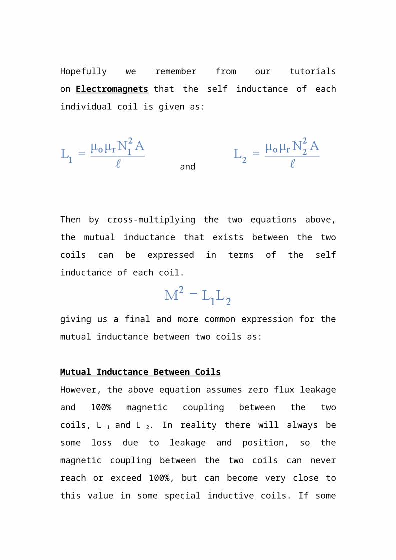
Hopefully we remember from our tutorials on Electromagnets that the
self inductance of each individual coil is given as:
and

Then by cross-multiplying the two equations above, the mutual
inductance that exists between the two coils can be expressed in terms
of the self inductance of each coil.
giving us a final and more common expression for the mutual
inductance between two coils as:
Mutual Inductance Between Coils
However, the above equation assumes zero flux leakage and 100%
magnetic coupling between the two coils, L 1 and L 2. In reality there will
always be some loss due to leakage and position, so the magnetic
coupling between the two coils can never reach or exceed 100%, but
can become very close to this value in some special inductive coils. If
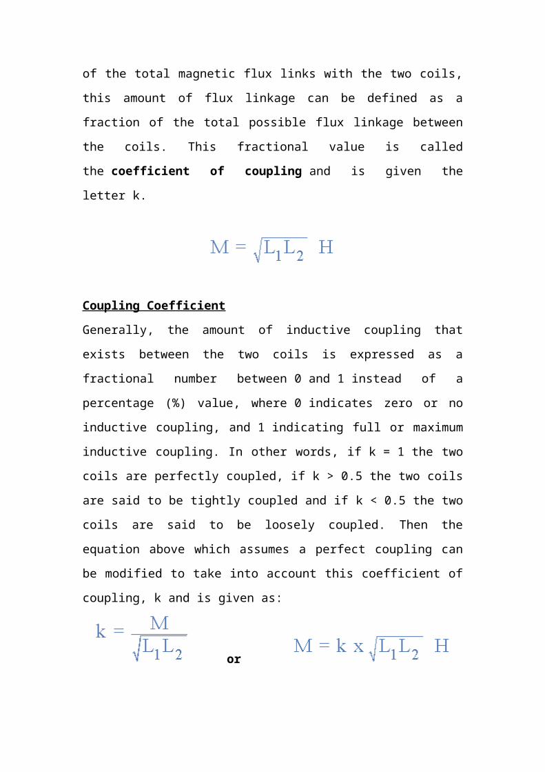
some of the total magnetic flux links with the two coils, this amount of
flux linkage can be defined as a fraction of the total possible flux linkage
between the coils. This fractional value is called the coefficient of
coupling and is given the letter k.
Coupling Coefficient
Generally, the amount of inductive coupling that exists between the two
coils is expressed as a fractional number between 0 and 1 instead of a
percentage (%) value, where 0 indicates zero or no inductive coupling,
and 1 indicating full or maximum inductive coupling. In other words,
if k = 1 the two coils are perfectly coupled, if k > 0.5 the two coils are
said to be tightly coupled and if k < 0.5 the two coils are said to be
loosely coupled. Then the equation above which assumes a perfect
coupling can be modified to take into account this coefficient of
coupling, k and is given as:
or
When the coefficient of coupling, k is equal to 1, (unity) such that all the
lines of flux of one coil cuts all of the turns of the other, the mutual
inductance is equal to the geometric mean of the two individual
inductances of the coils. So when the two inductances are equal
and L 1 is equal to L 2, the mutual inductance that exists between the
two coils can be defined as:
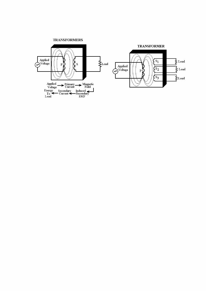
THE TRANSFORMER
When mutual induction exists between two coils or windings, a
change in current through one induces a voltage in the other.
Devices which make use of this principle are called transformer.
Every transformer has a primary winding and one or more
secondary windings. The primary winding receives electrical
energy from a power source and couples this energy to the
secondary winding by means of a changing magnetic field. The
energy appears as an EMF across the secondary winding, and if a
load is connected to the secondary, the energy is transferred to the
load.
By means of transformer, electrical energy can be transferred from
one circuit to another, with no physical connection between the
two. The transformer thus acts as a coupling device. Transformers
are also indispensable in A-C power distribution, since they can
convert electrical power at a given current and voltage into the
equivalent power at some other current and voltage.

OBSERVATIONS
S. No.
Distance between
Primary and
Secondary
Final Reading
1. 7 cm 0 V
2. 5 cm 1 V
3. 4 cm 2.5 V
4. 3 cm 4 V
5. 2 cm 6 V
No. of turns in Primary : 2000 turns
No. of turns in Secondary : 2000 turns
CIRCUIT DIAGRAM

APPARATUS USED
Transformer
Step Down 6-0-6 volts
Ferrite Rods
4” in length
Copper Insulated Wire
40 Gauge
Micro ampere meter
3 Volts
Diode
IN 4007
Main Lead
220 V A.C.
CONCLUSION
By above observations, it is found out that E.M.F. induced in the
secondary coil is inversely proportional to the distance between
the two coils i.e. when the distance between the primary and
secondary coil is less, then the E.M.F. induced in the secondary
coil is more and vice versa. This implies that the mutual induction
of two coils depends upon the distance between the primary and
secondary coil.
BIBLIOGRAPHY
S. No. Reference Author
1. Modern ABC of Physics Satish K. Gupta
2. PP Physics Digest
Dr. K.L. Gomber
&
K.L. Gogia
3. Text Book of NCERT
Arvind Kumar
A.N. Maheshwari
Abhai Mansingh
N. Mukunda
4. Modern Physics
K.B. Raja
(Ph.D.)
5. Fundamentals of physics
M. Subramanyam (M.Sc. Ph.D.)
&
Brij Lal (M. Sc.)