mutual coupling between iff/ssr microstrip antennas … · mutual coupling between iff/ssr...
TRANSCRIPT
284 Ł. SOROKOSZ, W. ZIENIUTYCZ, M. PERGOŁ, M. MAZUR, MUTUAL COUPLING BETWEEN IFF/SSR ANTENNAS WITH . . .
Mutual Coupling Between IFF/SSR Microstrip Antennaswith Reduced Transversal Size - Experimental Study
Łukasz SOROKOSZ1, Włodzimierz ZIENIUTYCZ1, Mariusz PERGOŁ1, Mateusz MAZUR2
1Dept. of Microwave and Antenna Engg., Gdansk Univ. of Technology, ul. Narutowicza 11/12, 80-233 Gdansk, Poland2 Przemysłowy Instytut Telekomunikacji S.A. (PIT S.A.), Al. Gen. J. Hallera 233A, 80-502 Gdansk, Poland
[email protected], [email protected], [email protected], [email protected]
Abstract. Mutual coupling between IFF/SSR microstrip an-tennas is investigated experimentally in this paper. At the be-gining configuration and performance of isolated microstripantenna fed by H-shaped coupling slot is presented. Next, thevertical and horizontal arrangement of the microstrip anten-nas array were investigated. The measurements of returnloss and coupling coefficients at two operating frequenciesfor the two orthogonal planes are presented and comparedwith the results of numerical calculations, showing satisfac-tory agreement.
KeywordsMutual coupling, microstrip antenna arrays, IFF/SRRsystems, patch antenna.
1. IntroductionThe effect of mutual coupling between the microstrip
antennas designed for IFF/SSR systems is investigated inthis paper. IFF (Identify Friend or Foe) and SSR (SecondarySurveillance Radar) systems are the standard systems usedin air traffic control [1]. IFF/SSR radars send impulses toflying objects at the frequency of 1.03 GHz. Configurationof impulses determines the type of inquiry. Transponders onthe flying objects receive the inquiry and generate responsesat the frequency of 1.09 GHz. Apart from the informationabout the identity of the flying object this response can alsocontain other important data (eg. velocity and altitude). Typ-ically, IFF/SSR radars are built in form of 1D/2D antennaarrays that can be mounted on planar or cylindrical surfaces.In order to design and build such an array the effect of cou-pling between the adjacent antennas has to be investigated.
The problem of mutual coupling between the mi-crostrip radiators is by far fundamental and for this reasonit is the subject of numerous papers. Generally, two ap-proaches were used in many studies independently for theapplied models: (i) calculations of the scattering matrix el-ements | Si j | (e.g. [2] - [5]) or (ii) calculations of mutualconductance/resistance (e.g. [6], [7]). The results presentedin the papers concern the effect of mutual coupling between
two neighboring radiators. However, two different situationsshould be studied in practical array: (i) the element is placedbetween two other ones and (ii) the radiator is placed on theperiphery of the array. This paper contains the results of nu-merical and experimental study of this problem, in two sepa-rate cases: horizontal and vertical configuration of antennas.
Configuration of the microstrip antenna with reducedtransversal size which was applied as the array element isshortly described in Section 2. The methodology of the per-formed study is discussed in Section 3. In the next section theresults of experimental study are presented and compared tothe results of numerical simulations. Finally, concluding re-marks are presented.
2. The Array ElementAs IFF/SSR array element we have used the microstrip
antenna with reduced transversal size due to the applicationof H-shaped coupling slot. Full study on this antenna, in-cluding the comparison of measurement and simulations, isdescribed in [8]. The H-shaped coupling slot in commonground plane allows to reduce the transversal size of the an-tenna for about 36 % compared to the antenna with rectan-gular coupling slot. This reduction is preferable with regardto: (i) easier fixing of the antennas on the curved surface ofcylindrical array and (ii) possibility to place two elementssufficiently closer to each other.
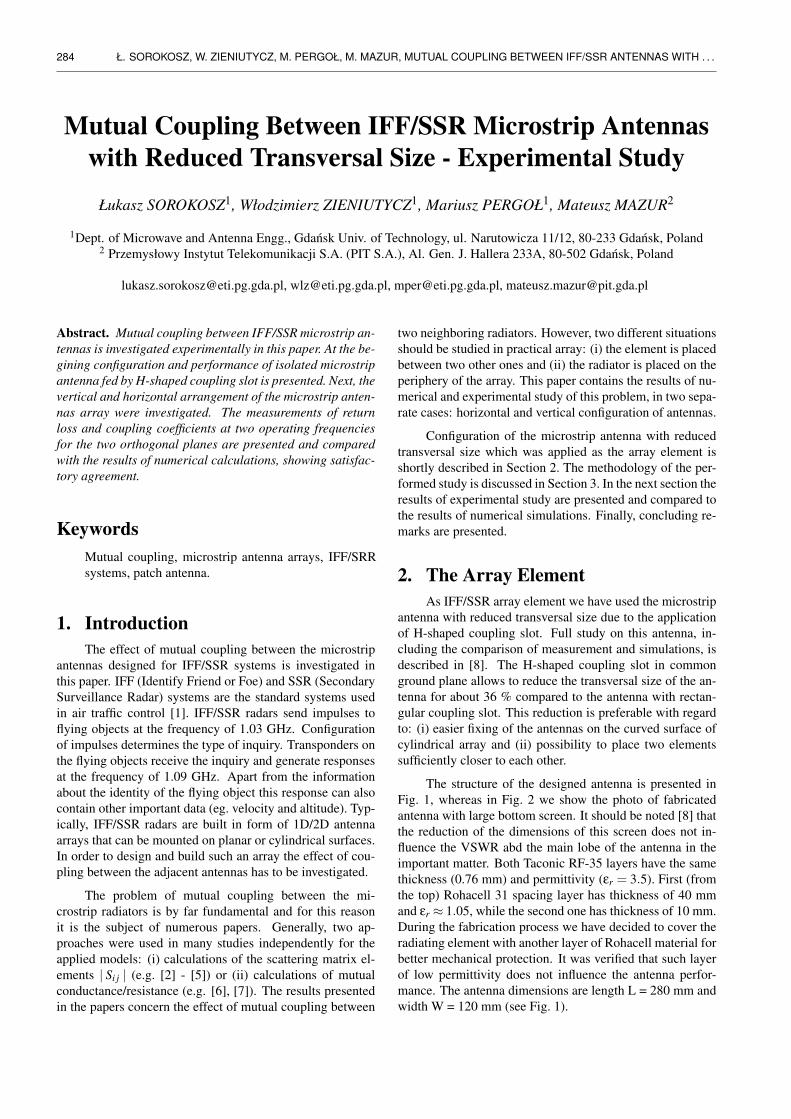
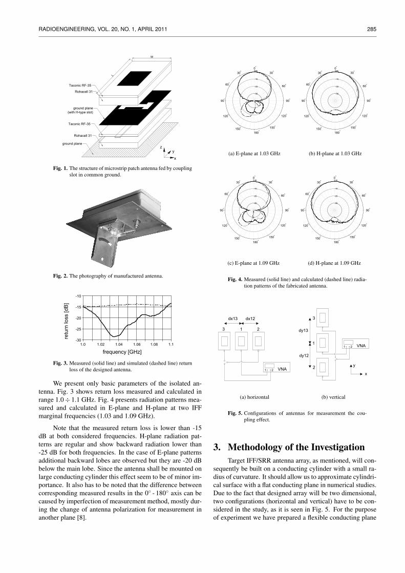
The structure of the designed antenna is presented inFig. 1, whereas in Fig. 2 we show the photo of fabricatedantenna with large bottom screen. It should be noted [8] thatthe reduction of the dimensions of this screen does not in-fluence the VSWR abd the main lobe of the antenna in theimportant matter. Both Taconic RF-35 layers have the samethickness (0.76 mm) and permittivity (εr = 3.5). First (fromthe top) Rohacell 31 spacing layer has thickness of 40 mmand εr ≈ 1.05, while the second one has thickness of 10 mm.During the fabrication process we have decided to cover theradiating element with another layer of Rohacell material forbetter mechanical protection. It was verified that such layerof low permittivity does not influence the antenna perfor-mance. The antenna dimensions are length L = 280 mm andwidth W = 120 mm (see Fig. 1).
RADIOENGINEERING, VOL. 20, NO. 1, APRIL 2011 285
Taconic RF-35
Rohacell 31
Taconic RF-35
ground plane
(with H-type slot)
ground plane
Rohacell 31
x
z
y
W
L
Fig. 1. The structure of microstrip patch antenna fed by couplingslot in common ground.
Fig. 2. The photography of manufactured antenna.
1.0 1.02 1.04 1.06 1.08 1.1
-10
-15
-20
-25
-30
frequency [GHz]
re
tu
rn
lo
ss [d
B]
Fig. 3. Measured (solid line) and simulated (dashed line) returnloss of the designed antenna.
We present only basic parameters of the isolated an-tenna. Fig. 3 shows return loss measured and calculated inrange 1.0÷ 1.1 GHz. Fig. 4 presents radiation patterns mea-sured and calculated in E-plane and H-plane at two IFFmarginal frequencies (1.03 and 1.09 GHz).
Note that the measured return loss is lower than -15dB at both considered frequencies. H-plane radiation pat-terns are regular and show backward radiation lower than-25 dB for both frequencies. In the case of E-plane patternsadditional backward lobes are observed but they are -20 dBbelow the main lobe. Since the antenna shall be mounted onlarge conducting cylinder this effect seem to be of minor im-portance. It also has to be noted that the difference betweencorresponding measured results in the 0◦ - 180◦ axis can becaused by imperfection of measurement method, mostly dur-ing the change of antenna polarization for measurement inanother plane [8].
0dB
30
60
90
120
150
180
150
120
90
60
30
0
-10
-20
-30
o
o
o
o
o
o
o
o
o
o
o
o
(a) E-plane at 1.03 GHz
0dB
30
60
90
120
150
180
150
120
90
60
30
0
-10
-20
-30
o
o
o
o
o
o
o
o
o
o
o
o
(b) H-plane at 1.03 GHz
0dB
30
60
90
120
150
180
150
120
90
60
30
0
-10
-20
-30
o
o
o
o
o
o
o
o
o
o
o
o
(c) E-plane at 1.09 GHz
0dB
30
60
90
120
150
180
150
120
90
60
30
0
-10
-20
-30
o
o
o
o
o
o
o
o
o
o
o
o
(d) H-plane at 1.09 GHz
Fig. 4. Measured (solid line) and calculated (dashed line) radia-tion patterns of the fabricated antenna.
VNA
1 2
3 1 2
dx13 dx12
(a) horizontal
VNA
1 2
3
1
2
dy13
dy12
y
x
(b) vertical
Fig. 5. Configurations of antennas for measurement the cou-pling effect.
3. Methodology of the InvestigationTarget IFF/SRR antenna array, as mentioned, will con-
sequently be built on a conducting cylinder with a small ra-dius of curvature. It should allow us to approximate cylindri-cal surface with a flat conducting plane in numerical studies.Due to the fact that designed array will be two dimensional,two configurations (horizontal and vertical) have to be con-sidered in the study, as it is seen in Fig. 5. For the purposeof experiment we have prepared a flexible conducting plane

286 Ł. SOROKOSZ, W. ZIENIUTYCZ, M. PERGOŁ, M. MAZUR, MUTUAL COUPLING BETWEEN IFF/SSR ANTENNAS WITH . . .
shown in Fig. 6. On this sheet one can see small mountingholes that correspond to the step taken in computer simula-tions and measurements.
By using three antennas with reduced bottom screenwe can investigate two effects: (i) the influence of marginalsources ’3’ and ’2’ on the central source ’1’ (ii) the impact oftwo sources (e.g. ’1’ and ’3’) on the marginal element of thearray (e.g. ’2’). In both configurations central antenna wasconnected to the first port of the vector network analyzer, inthis case HP 8753 D. Second port of the VNA was loadedwith one of the marginal antennas. All measurements forboth configurations and different distances between the an-tennas (denoted as dx12, dx13, dy12 and dy13) were performedat two frequencies from the IFF band (1.03 GHz and 1.09GHz).
Computer simulations were performed using Ansoft’sHFSS 12.1 software. This environment is fully three di-mensional (3D) and allows to build an acurate model of theexperimental setting. It also needs to be noted that singleantenna was modeled and optimised due to reflection coef-ficient, and then fabricated. Manufactured antenna had to beoptimised once again, yet it was verified that slight changesin antenna’s dimensions do not affect the results of this study.Final results of measurements compared to the results ofsimulations are presented and discussed in the next section.
(a) horizontal (b) vertical
Fig. 6. Flexible conducting plane for coupling measurements(with mounted antennas).
4. Results of Measurementand Numerical StudySince both configurations of the antennas in Fig. 5 are
symmetrical (dx12 = dx13 and dy12 = dy13) only the couplingbetween elements ’1’ and ’2’ in the presence of ’3’ is consid-ered. For connected ’1’ and ’3’ we have received almost thesame results. We do not consider phase parameters in thestudy since some difference may be introduced by coaxialcables connecting the antennas to the VNA (this effect was
not included in the simulations).
In Fig. 7 and Fig. 8 we present scattering parameters forhorizontal configurations at 1.03 GHz and 1.09 GHz, respec-tively. In this setting the distance step was equal to 15 mm,between 120 and 180 mm. We observe satisfying levels ofreturn losses. Differences between measured and calculatedvalues of the return loss are acceptable and do not exceed5 dB in the worst case. They can be explained by imperfec-tions in the measurements, where return loss of the antennawas measured indirectly with the flexible coaxial cable. Forcoupling coefficients (S21, S12) simulated curves agree wellwith experimental ones, only for f = 1.03 GHz we see impor-tant disagreement in case when dx12 = 120 mm. Generally,results of simulations are confirmed by the results of mea-surement.
120 130 140 150 160 170 180-25
-20
-15
-10
|S11
| [dB
]dx12 [mm]
120 130 140 150 160 170 180-25
-20
-15
-10
|S12
|, |S
21| [
dB]
dx12 [mm]
120 130 140 150 160 170 180
-18
-16
-14
dx12 [mm]
|S22
| [dB
]
-20
Fig. 7. Scattering parameters, horizontal configuration for1.03 GHz, measurement (solid line) and simulation re-sults (dashed line).
120 130 140 150 160 170 180
-18
-16
-14
|S11
| [dB
]
dx12 [mm]
-20
120 130 140 150 160 170 180-25
-20
-15
-10
|S12
|, |S
21| [
dB]
dx12 [mm]
120 130 140 150 160 170 180-20
-18
-16
-14
|S22
| [dB
]
dx12 [mm]
Fig. 8. Scattering parameters, horizontal configuration for1.09 GHz, measurement (solid line) and simulation re-sults (dashed line).
RADIOENGINEERING, VOL. 20, NO. 1, APRIL 2011 287
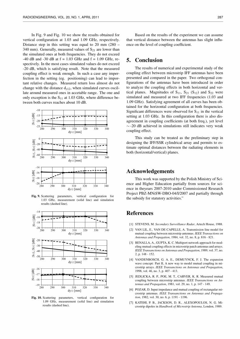
In Fig. 9 and Fig. 10 we show the results obtained forvertical configuration at 1.03 and 1.09 GHz, respectively.Distance step in this setting was equal to 20 mm (280 –340 mm). Generally, measured values of S21 are lower thanthe simulated ones at both frequencies. They do not exceed-40 dB and -30 dB at f = 1.03 GHz and f = 1.09 GHz, re-spectively. In the most cases simulated values do not exceed-20 dB, which is satisfying result. Note that the measuredcoupling effect is weak enough. In such a case any imper-fection in the setting (eg. positioning) can lead to impor-tant relative changes. Measured return loss almost do notchange with the distance dy12, when simulated curves oscil-late around measured ones in accetable range. The one andonly exception is the S11 at 1.03 GHz, where difference be-tween both curves reaches about 10 dB.
280 290 300 310 320 330 340-25
-20
-15
-10
|S11
| [dB
]
dy12 [mm]
280 290 300 310 320 330 340-60
-40
-20
0
|S12
|, |S
21| [
dB]
dy12 [mm]
280 290 300 310 320 330 340
-18
-16
-14
|S22
| [dB
]
dy12 [mm]
-20
Fig. 9. Scattering parameters, vertical configuration for1.03 GHz, measurement (solid line) and simulationresults (dashed line).
280 290 300 310 320 330 340
-18
-16
-14
|S11
| [dB
]
dy12 [mm]
-20
-50
-40
-30
-20
280 290 300 310 320 330 340
|S12
|, |S
21| [
dB]
dy12 [mm]
-18
-17
-16
280 290 300 310 320 330 340
|S22
| [dB
]
dy12 [mm]
-19
Fig. 10. Scattering parameters, vertical configuration for1.09 GHz, measurement (solid line) and simulationresults (dashed line).
Based on the results of the experiment we can assumethat vertical distance between the antennas has slight influ-ence on the level of coupling coefficient.
5. ConclusionThe results of numerical and experimental study of the
coupling effect between microstrip IFF antennas have beenpresented and compared in the paper. Two orthogonal con-figurations of the antennas have been introduced in orderto analyze the coupling effects in both horizontal and ver-tical planes. Magnitudes of S11, S21 (S12) and S22 weresimulated and measured at two IFF frequencies (1.03 and1.09 GHz). Satisfying agreement of all curves has been ob-tained for the horizontal configuration at both frequencies.Significant differences were observed for S11 in the verticalsetting at 1.03 GHz. In this configuration there is also dis-agreement in coupling coefficients (at both freq.), yet level∼ -20 dB achieved in simulations still indicates very weakcoupling effect.
This study can be treated as the preliminary step indesigning the IFF/SSR cylindrical array and permits to es-timate optimal distances between the radiating elements inboth (horizontal/vertical) planes.
AcknowledgementsThis work was supported by the Polish Ministry of Sci-
ence and Higher Education partially from sources for sci-ence in theyears 2007-2010 under Commissioned ResearchProject PBZ-MNiSW-DBO-04/I/2007 and partially throughthe subsidy for statutory activities.”
References
[1] STEVENS, M. Secondary Surveillance Radar, Artech House, 1988.
[2] VAN LIL, E., VAN DE CAPELLE, A. Transmission line model formutual coupling between microstrip antennas. IEEE Transactions onAntennas and Propagation, 1984, vol. 32, no. 8, p. 816 - 821.
[3] BENALLA, A., GUPTA, K. C. Multiport network approach for mod-eling mutual coupling effects in microstrip patch antennas and arrays.IEEE Transanctions on Antennas and Propagation, 1989, vol. 37, no.2, p. 148 - 152.
[4] VANDENBOSCH, G. A. E., DEMUYNCK, F. J. The expansionwave concept: Part II, A new way to model mutual coupling in mi-crostrip arrays. IEEE Transanctions on Antennas and Propagation,1998, vol. 46, no. 3, p. 407 - 413.
[5] JEDLICKA, R. P., POE, M. T., CARVER, K. R. Measured mutualcoupling between microstrip antennas. IEEE Transanctions on An-tennas and Propagation, 1981, vol. 29, no. 1, p. 147 - 149.
[6] POZAR, D. Input impedance and mutual coupling of rectangular mi-crostrip antennas. IEEE Transanctions on Antennas and Propaga-tion, 1982, vol. 30, no. 6, p. 1191 - 1196.
[7] KATEHI, P. B., JACKSON, D. R., ALEXOPOULOS, N. G. Mi-crostrip dipoles in Handbook of Microstrip Antenna, London, 1989.

288 Ł. SOROKOSZ, W. ZIENIUTYCZ, M. PERGOŁ, M. MAZUR, MUTUAL COUPLING BETWEEN IFF/SSR ANTENNAS WITH . . .
[8] ZIENIUTYCZ, W., MAZUR, M., PERGOL, M. Effect of groundplane size on radiation pattern in iff/ssr microstrip antenna on thicksubstrate fed by h type slot. Microwave and Optical Technology Let-ters, 2010, vol. 52, no. 12, p. 2679 - 2682.
About Authors. . .
Łukasz SOROKOSZ was born in Wałcz, Poland. He re-ceived the M.Sc. from Gdansk University of Technology in2009. In 2009, after receiving M.Sc., he started Ph.D. studiesat the same university. His research interests include mainlyantennas, propagation as well as planar passive microwavecircuits.
Mariusz PERGOŁ was born in Gdansk, Poland. He re-ceived his M.Sc. from Gdansk University of Technology in2005. After receiving M.Sc. he started Ph.D. studies at thesame university. His research interests include mainly UWBantennas and propagation.
Włodzimierz ZIENIUTYCZ was born in Gdansk, Polandin 1950. He received the M.Sc., Ph.D. and D.Sc. fromGdansk University of Technology where he is currently As-sociate Professor in Faculty of Electronics, Telecommunica-tions and Informatics. In 1984 he was a research fellow at theStructures Rayonnantes Laboratory U.A. au C.N.R.S 834,Rennes, France and he spent 4 months at Chalmers Univer-sity of Technology, Geteborg, Sweden in 1991, by SwedishInstitute. His research interests include effect of radiationfrom MIC lines and antennas, especially for UWB.
Mateusz MAZUR was born in Gdynia, Poland. He re-ceived the M.Sc. from Gdansk University of Technology in1999. Since 2000 is affiliated with PIT wherefrom he re-ceived the Ph.D. in 2007. Since 2009 he is editor in chief of”Postepy Radiotechniki” (eng.: ”Innovations in Radio Tech-nique”) and a member of Scientific Council in PIT S.A.. Hismain area of interests are antenna systems, passive devicesand also lean manufacturing.