mutual aid tanker shuttle - som - state of … aid tanker shuttle • introduce yourself • point...
TRANSCRIPT

MUTUAL AID TANKER SHUTTLE
INSTRUCTOR MANUAL Revised February 2009
Office of Fire Fighter Training www.michigan.gov/bfs

2
SLIDE 1
11
Mutual Aid Tanker ShuttleMutual Aid Tanker Shuttle
Office of Fire Fighter Trainingwww.michigan.gov/bfs
SLIDE 2
22
Water, water, everywhere….Water, water, everywhere….
SLIDE 3
33
……but not always accessible! but not always accessible!
SLIDE 4
44
Water supplies can Water supplies can sometimes be sometimes be difficult to find. difficult to find.
They can also be They can also be obvious but very obvious but very difficult to access difficult to access
due to their due to their surroundings.surroundings.
MUTUAL AID TANKER SHUTTLE • Introduce yourself • Point out exits • Point out restrooms • Explain when to expect breaks • Explain that this is a 4 hour classroom and 4 hour practical course
WATER, WATER, EVERYWHERE….
• This house fire wouldn’t seem to have a water supply issue with a lake in its front yard, but it does…..
…but not always accessible!
• This home was in a development that was completely land-locked. Drafting operations were considerably hampered, which affected the initial attack.
Water supplies can sometimes be difficult to find. They can also be obvious but very difficult to access due to their surrounds
• The FD should have a pre-incident plan that shows all available water sources.
• Coverage areas should be preplanned to ensure an adequate water supply.
• It is important to have a pre-incident plan that contains: • Best fill site for the incident location • Alternative fill sites • Dump site(s) • Best route of travel for shuttle apparatus

3
SLIDE 5
55
Goal of this program:Goal of this program:
To assist Michigan fire departments in To assist Michigan fire departments in providing a water supply necessary for fire providing a water supply necessary for fire
suppression in jurisdictions where it has suppression in jurisdictions where it has been determined that there is an been determined that there is an
inadequate water supply for firefighting.inadequate water supply for firefighting.
SLIDE 6
66
ObjectivesObjectives
Identify the apparatus requirements for a water shuttleIdentify the apparatus requirements for a water shuttle (NFPA 1002 (NFPA 1002 [2009], 8[2009], 8--2.1,82.1,8--2.2, 82.2, 8--2.3)2.3)
Identify the requirements for setting up a water shuttle operatiIdentify the requirements for setting up a water shuttle operation:on:
Water shuttle fill site:Water shuttle fill site: Maneuver and position a mobile water supply Maneuver and position a mobile water supply apparatus at a water shuttle fill site, given a fill site locatiapparatus at a water shuttle fill site, given a fill site location and one or on and one or more supply hose, so that the apparatus is correctly positioned,more supply hose, so that the apparatus is correctly positioned, supply supply hose are attached to the intake connections without having to sthose are attached to the intake connections without having to stretch retch additional hose, and no objects are struck at the fill site.additional hose, and no objects are struck at the fill site. (NFPA 1002 (NFPA 1002 [2009], 10.2.1)[2009], 10.2.1)Water shuttle dump site:Water shuttle dump site: Maneuver and position a mobile water supply Maneuver and position a mobile water supply apparatus at a water shuttle dump site, given a dump site and a apparatus at a water shuttle dump site, given a dump site and a portable water tank, so that all of the water being discharged fportable water tank, so that all of the water being discharged from the rom the apparatus enters the portable tank and no objects are struck at apparatus enters the portable tank and no objects are struck at the the dump site.dump site. (NFPA 1002 [2009], 10.2.2)(NFPA 1002 [2009], 10.2.2)
SLIDE 7
77
ObjectivesObjectives
Portable Tank operations: Portable Tank operations: Establish a water shuttle dump site, given Establish a water shuttle dump site, given two or more portable water tanks, lowtwo or more portable water tanks, low--level strainers, water transfer level strainers, water transfer equipment, fire hose, and a fire apparatus equipped with a fire equipment, fire hose, and a fire apparatus equipped with a fire pump, pump, so that the tank being drafted from is kept full at all times, tso that the tank being drafted from is kept full at all times, the tank he tank being dumped into is emptied first, and the water is transferredbeing dumped into is emptied first, and the water is transferredefficiently from one tank to the next.efficiently from one tank to the next. (NFPA 1002 [2009], 10.2.3)(NFPA 1002 [2009], 10.2.3)
Describe how to evaluate tanker performance in a water shuttle Describe how to evaluate tanker performance in a water shuttle operationsoperations (NFPA 1002 [1998] 8(NFPA 1002 [1998] 8--2.1b)2.1b)
Goals of This Program: To assist Michigan fire departments in providing a water supply necessary for fire suppression in jurisdictions where it has been determined that there is an inadequate water supply for firefighting. OBJECTIVES:
Identify the apparatus requirements for a water shuttle (NFPA 1002 [2009], 8-2.1,8-2.2, 8-2.3)
Identify the requirements for setting up a water shuttle operation:
Water shuttle fill site: Maneuver and position a mobile water supply apparatus at a water shuttle fill site, given a fill site location and one or more supply hose, so that the apparatus is correctly positioned, supply hose are attached to the intake connections without having to stretch additional hose, and no objects are struck at the fill site. (NFPA 1002 [2009], 10.2.1)
Water shuttle dump site: Maneuver and position a mobile water supply apparatus at a water shuttle dump site, given a dump site and a portable water tank, so that all of the water being discharged from the apparatus enters the portable tank and no objects are struck at the dump site. (NFPA 1002 [2009], 10.2.2)
OBJECTIVES:
Portable Tank operations: Establish a water shuttle dump site, given two or more portable water tanks, low-level strainers, water transfer equipment, fire hose, and a fire apparatus equipped with a fire pump, so that the tank being drafted from is kept full at all times, the tank being dumped into is emptied first, and the water is transferred efficiently from one tank to the next. (NFPA 1002 [2009], 10.2.3)
Describe how to evaluate tanker performance in a water shuttle
operations (NFPA 1002 [1998] 8-2.1b)

4
SLIDE 8
88
DefinitionsDefinitions
• Alternate Water Supply: Water supplies provided to meet the minimum fire flow/duration requirements where no municipal water system exists; or to supplement an inadequate municipal-type water supply.
•Automatic Aid: A plan developed between two or more fire departments for immediate joint response on fire alarms.
•Dry Hydrant: An arrangement of pipe permanently connected to a water source other than a piped, pressurized water supply system that provides a ready means of water supply for fire-fighting purposes and that utilizes the drafting capability of a fire department pump.
• Large Diameter Hose (LDH): A hose of 3-1/2 inch size or larger.
SLIDE 9
99
Fire Department: An organization providing fire suppression, rescue, and related activities.
•Minimum Water Supply: The quantity of water required for fire control and extinguishment.
• Mobile Water Supply Apparatus (Tanker, Tender): A vehicle designed primarily for the safe and effective pickup, transport, and delivery of water to fire emergency scenes where other apparatus or pumping equipment provide tactical fire stream application.
Water Delivery Rate: The minimum amount of water per minute (in gpm or L/min), required to be delivered to the fire scene via mobile water supply apparatus, hose lines, or a combination of both.
Water Supply Officer (WSO): The fire department officer or designee responsible for providing water for fire-fighting purposes.
SLIDE 10
1111
Factors that may require tanker shuttle Factors that may require tanker shuttle operations include:operations include:
Incident is far from a water supply source Incident is far from a water supply source
DEFINITIONS: • Alternate Water Supply: Water supplies provided to meet the
minimum fire flow/duration requirements where no municipal water system exists; or to supplement an inadequate municipal-type water supply.
• Automatic Aid: A plan developed between two or more fire departments for immediate joint response on fire alarms.
• Dry Hydrant: An arrangement of pipe permanently connected to a water source other than a piped, pressurized water supply system that provides a ready means of water supply for fire-fighting purposes and that utilizes the drafting capability of a fire department pump.
• Large Diameter Hose (LDH): A hose of 3-1/2 inch size or larger. Fire Department: An organization providing fire suppression, rescue, and related activities.
• Minimum Water Supply: The quantity of water required for fire control and extinguishment.
• Mobile Water Supply Apparatus (Tanker, Tender): A vehicle designed primarily for the safe and effective pickup, transport, and delivery of water to fire emergency scenes where other apparatus or pumping equipment provide tactical fire stream application.
• Water Delivery Rate: The minimum amount of water per minute (in gpm or L/min), required to be delivered to the fire scene via mobile water supply apparatus, hose lines, or a combination of both.
• Water Supply Officer (WSO): The fire department officer or designee responsible for providing water for fire-fighting purposes.
Factors that may require tanker shuttle operations include:
Incident is far from a water supply source Sometimes a water source may be close to the incident but is not available for use.
• Ponds/lakes/streams can be hard to access due to road conditions or even the lack of roads
• The water source may have inadequate volumes of water to be useful
• Frozen ponds and lakes can make it difficult to access the water • Droughts can reduce water levels. • Consideration should be given to a “water usage” agreement to
access water sources on private property.

5
SLIDE 11
1212
Factors that may require tanker shuttle Factors that may require tanker shuttle operations include:operations include:
Incident is far from a water supply source Incident is far from a water supply source Inability to access a close water supplyInability to access a close water supply
SLIDE 12
1313
Factors that may require tanker shuttle Factors that may require tanker shuttle operations include:operations include:
Incident is far from a water supply source Incident is far from a water supply source Inability to access a close water supplyInability to access a close water supplyRelay pumping is not practicalRelay pumping is not practical
SLIDE 13
1414
Factors that may require tanker shuttle Factors that may require tanker shuttle operations include:operations include:
Incident is far from a water supply source Incident is far from a water supply source Inability to access a close water supplyInability to access a close water supplyRelay pumping is not practicalRelay pumping is not practicalInadequate or failed water supply from municipal Inadequate or failed water supply from municipal systemsystem
Inability to access a close water supply Sometimes a water source may be close to the incident but is not available for use.
• Ponds/lakes/streams can be hard to access due to road conditions or even the lack of roads
• The water source may have inadequate volumes of water to be useful
• Frozen ponds and lakes can make it difficult to access the water • Droughts can reduce water levels.
Consideration should be given to a “water usage” agreement to access water sources on private property. Relay pumping is not practical
• Due to the distance from the water source to the incident scene, it may not be practical to set up a relay hose line.
• A large diameter hose (LDH) setup is time consuming and may deplete the attack pumper of water during the setup process if this is the only method of supplying additional water. If a LDH relay is going to be used, the water shuttle should be initiated first to ensure sufficient water during the initial phases of firefighting. The LDH relay can supplement or replace the shuttle operations after it is put into operation.
• The lack of sufficient pumpers and/or LDH may prevent a relay from being setup.
• Friction loss must be factored in when deciding whether a shuttle or relay operation is best suited for the incident.
Inadequate or failed water supply from municipal system
• Broken and/or frozen hydrants will require alternate water sources• If the incident overwhelms the hydrant volume, a water shuttle
may be needed to supplement it.

6
SLIDE 14
1515
A request for a
“TANKER”
on the west coast will get you a
plane or helicopter
carrying water
What is a What is a “Tanker/Tender”“Tanker/Tender” ??
SLIDE 16
1616
A request for a
“TANKER”in Michigan will usually get you a vehicle carrying
water. The updated term nationwide for this type of vehicle is
“Water tender”.This type of vehicle may carry water in the amounts of This type of vehicle may carry water in the amounts of
1,000 to 8,000 gallons1,000 to 8,000 gallons..
SLIDE 17
1616
Tankers come in all shapes and sizesTankers come in all shapes and sizes
What is a “Tanker/Tender” ? A request for a “TANKER” on the west coast will get you a plane or helicopter carrying water
• The fire service uses terms that may be confusing depending on where you live in the United States.
• On the west coast a tanker is usually an aircraft/helicopter that will dump water from an on-board tank.
• In Michigan, when the USFS and/or DNR use firefighting aircraft, the terminology must be “tender” instead of a “tanker”. Firefighters have been covered in a clay slurry after a drop from aircraft when they’ve mixed up these two terms.
A request for a “TANKER” in Michigan will usually get you a vehicle carrying water. The updated term nationwide for this type of vehicle is “Water tender”. This type of vehicle may carry water in the amounts of 1,000 to 8,000 gallons. There continues to be a controversy over the use of tanker versus water tender. Firefighters News Aug/Sept 1996 from retired Phoenix Chief Alan Brunacini: “I realize an important part of ICS is that we all hold hands and begin to standardize what we call stuff. It doesn’t make a lick of sense (at least to me) to rename vehicles we use everyday of the year on a variety of fires throughout the country, and then use that common, widespread and descriptive name to identify only 50 special airplanes (50 airplanes!) that we use only during a relatively short season and on only one type of fire (wildland)” “My suggested solution is for us to keep calling tankers, ‘tankers’, and for wildland firefighters to use the new term “BADLOW”, which means Big Aircraft Dropping Lots of Water.” TANKERS COME IN ALL SHAPES AND SIZES
• Point out the different types of tankers in the slide. Note: some FD’s in Michigan use a “vacuum tanker” unit due to the ease in filling/dumping. One is shown in the upper left hand photo.
• Department must choose size of tank for tanker based on: • local water requirements • road conditions • bridge weight restrictions • Water source locations • Mutual aid • Compatibility of equipment from different FD’s
7
SLIDE 18
1818
TANKER CONSTRUCTIONTANKER CONSTRUCTIONNFPA 1901 (2009) Standard for Automotive Fire NFPA 1901 (2009) Standard for Automotive Fire
ApparatusApparatus
SLIDE 19
1414
NFPA 1912 Standard for Fire Apparatus NFPA 1912 Standard for Fire Apparatus RefurbishingRefurbishing
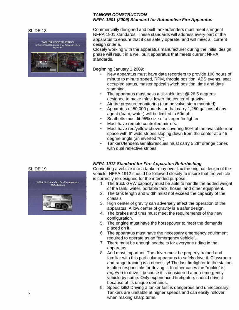
TANKER CONSTRUCTION NFPA 1901 (2009) Standard for Automotive Fire Apparatus Commercially designed and built tanker/tenders must meet stringent NFPA 1901 standards. These standards will address every part of the apparatus to ensure that it can safely operate, and will meet all current design criteria. Closely working with the apparatus manufacturer during the initial design phase will result in a well built apparatus that meets current NFPA standards. Beginning January 1,2009:
• New apparatus must have data recorders to provide 100 hours of minute to minute speed, RPM, throttle position, ABS events, seat occupied status, master optical switch position, time and date stamping.
• The apparatus must pass a tilt-table test @ 26.5 degrees; designed to make mfgs. lower the center of gravity.
• Air tire pressure monitoring (can be valve stem mounted) • Apparatus of 50,000 pounds, or that carry 1,250 gallons of any
agent (foam, water) will be limited to 60mph. • Seatbelts must fit 95% size of a larger firefighter. • Must have remote controlled mirrors. • Must have red/yellow chevrons covering 50% of the available rear
space with 6” wide stripes sloping down from the center at a 45 degree angle (an inverted “V”)
• Tankers/tenders/aerials/rescues must carry 5 28” orange cones with dual reflective stripes.
NFPA 1912 Standard for Fire Apparatus Refurbishing Converting a vehicle into a tanker may over-tax the original design of the vehicle. NFPA 1912 should be followed closely to insure that the vehicle is correctly re-designed for the intended purpose.
1. The truck GVW capacity must be able to handle the added weight of the tank, water, portable tank, hoses, and other equipment.
2. The tank length and width must not exceed the capacity of the chassis.
3. High center of gravity can adversely affect the operation of the apparatus. A low center of gravity is a safer design.
4. The brakes and tires must meet the requirements of the new configuration.
5. The engine must have the horsepower to meet the demands placed on it.
6. The apparatus must have the necessary emergency equipment required to operate as an “emergency vehicle”.
7. There must be enough seatbelts for everyone riding in the apparatus.
8. And most important: The driver must be properly trained and familiar with this particular apparatus to safely drive it. Classroom and range training is a necessity! The last firefighter to the station is often responsible for driving it. In other cases the “rookie” is required to drive it because it is considered a non-emergency vehicle by some. Only experienced firefighters should drive it because of its unique demands.
9. Speed kills! Driving a tanker fast is dangerous and unnecessary. Tankers are unstable at higher speeds and can easily rollover when making sharp turns.

8
1919
Tanker Conversion FormulaTanker Conversion Formula
1OGT + RL + S = Disaster1OGT + RL + S = Disaster
1 Old Gas Truck + Red lights + Siren = Disaster1 Old Gas Truck + Red lights + Siren = Disaster
SLIDE 20
2020
Tank BafflesTank Baffles
Click here for videoTanker Rollover.wmv
SLIDE 21
1616
REMEMBERREMEMBER“Cutting costs” doesn’t mean “cutting corners”“Cutting costs” doesn’t mean “cutting corners”
Tanker Conversion Formula 1OGT + RL + S = Disaster When converting vehicles from non-fire vehicles into tankers, always remember this formula: 1 Old Gas Truck + Red lights + Siren = Disaster TANK BAFFLES
• Baffles are designed so that water in the tank will not be able to slosh around. The baffles break up the movement of water, which could jeopardize the drivers’ ability to handle the apparatus.
• It is very important for tanks to have enough baffling to reduce side-to-side and front-to-back movement of water.
• Un-baffled or under-baffled tanks can lead to loss of vehicle control resulting in flipping over the apparatus.
It is important to remember that the weight of a tanker, combined with water movement within the tank and a high center of gravity, will make driving a tanker more challenging. The driver must never allow the fire incident to overwhelm his/her ability to operate this unique type of equipment. CLICK ON ICON ON SLIDE Remember, cutting costs doesn’t mean cutting corners. These fatal accidents resulted from loss of control of the tanker. When retrofitting a vehicle originally intended to transport liquids other than water, make sure that you don’t cut corners! Remember, water can weigh much more than the product that the vehicle was originally designed to carry. Follow NFPA 1912 standards! Was the vehicle originally designed for a lighter liquid? Milk: 8.6 pounds/gal Water: 8.3 pounds/gal Corn oil: 7.8 pounds/gal Heating oil: 7.5 pounds/gal Diesel fuel: 6.8 pounds/gal Gasoline: 6.0 pounds/gal

9
SLIDE 22
2222
Common Tanker ElementsCommon Tanker Elements
At least one large discharge At least one large discharge Water discharge is either a gravity, jet, or pumped off a Water discharge is either a gravity, jet, or pumped off a nurse tankernurse tanker2,500 gallons or less (Most efficient for loading and 2,500 gallons or less (Most efficient for loading and unloading)unloading)Quick connect fittings decrease fill timesQuick connect fittings decrease fill times
Camlock Storz SLIDE 23
2323
Gravity dumps employ 8Gravity dumps employ 8--inch or larger round or square inch or larger round or square piping with valve that extends to exterior of apparatus. piping with valve that extends to exterior of apparatus.
Either type has a valve control which may operate Either type has a valve control which may operate manually or have an electric or air operated valvemanually or have an electric or air operated valve
Square Dump
Round Dump
SLIDE 24
2424
Jet dumps employ use of a small diameter, inJet dumps employ use of a small diameter, in--line line discharge pipe located in the piping of a large tank discharge pipe located in the piping of a large tank
discharge. The fire pump on the apparatus discharge. The fire pump on the apparatus supplies water into the small pipe.supplies water into the small pipe.
This creates a venturi effect that increases water This creates a venturi effect that increases water flow through a large tank discharge.flow through a large tank discharge.
COMMON TANKER ELEMENTS • It is important to remember that these are “common elements”
and by no means cover all the design elements for a tanker! • Tankers with tanks of less than 2,500 gallons and quick
unloading times are most efficient. Mutual Aid departments should work toward standardizing fittings and threads.
• Existing tanks that are being retrofitted with large diameter discharge valves should follow manufacturer’s instructions so tank isn’t structurally damaged.
• The two primary ways of increasing efficiency is to decrease both fill and dump times. Response times and travel times between fill/dump sites remains fairly constant. Making up time by increasing speed during travel is dangerous.
• Tankers using 3 inch supply lines for filling should have at least two external fill connections piped directly to tank. If LDH is used, one fill connect adequate.
• Fill pipes should have either Storz or camlock fittings to reduce fill time.
Gravity dumps employ 8-inch or larger round or square piping with valve that extends to exterior of apparatus. Either type has a valve control which may operate manually or have an electric or air operated valve
• Some gravity dumps also have extension chutes which make it easier to dump the water into the portable tank.
• NFPA 1901 requires only 1 discharge. It is highly recommended that each tanker be equipped with at least three discharge dumps: one at rear and one on either side of apparatus.
• Gravity dumps rely on gravitational pull to empty water from tank.
Jet dumps employ use of a small diameter, in-line discharge pipe located in the piping of a large tank discharge. The fire pump on the apparatus supplies water into the small pipe. This creates a venturi effect that increases water flow through a large tank discharge.
• In-line jets pumped at 150 psi provide 700-800 gpm when pumped through a 4-inch pipe.
Four primary disadvantages associated with jet dumps:
1. Fire pump engaged before dumping water from tank increases dump time.
2. Time saved by increased flow from tank negated by additional time needed to put pump in operation
3. Water still discharged if pump not operating, but will be considerably slower rate than if dump valve designed for gravity dump
4. Increases the cost of apparatus purchase price

10
SLIDE 25
2525
Tankers must have adequately vented tanks for filling Tankers must have adequately vented tanks for filling and discharge operations to prevent tank damage. and discharge operations to prevent tank damage.
The vent size should be The vent size should be 11--1/2 times1/2 times the size of the the size of the
discharge.discharge.
VENT
SLIDE 26
2626
The water shuttle operation relies on The water shuttle operation relies on constant movement of apparatus between constant movement of apparatus between the emergency scene and the water supply the emergency scene and the water supply
sourcesource
SLIDE 27
2727
Ensuring a constant tanker water Ensuring a constant tanker water supply relies on the following factors:supply relies on the following factors:
• Command of water shuttle operations
• Water sources
• Dumping water supply at emergency scene
• Tanker fill and dump site operations
• Travel routes for tankers
• Tanker design
SLIDE 28
2828
Water Supply OfficerWater Supply Officer
The Incident The Incident Commander needs Commander needs to assign a Water to assign a Water Supply Officer to Supply Officer to
ensure an efficient ensure an efficient and safe water and safe water
shuttle operationshuttle operation
Tankers must have adequately vented tanks for filling and discharge operations to prevent tank damage. The vent size should be 1-1/2 times the size of the discharge.
• Failure to have adequate venting during quick filling
operations may result in dramatic pressure failure of tank
• Failure to have adequate venting during dumping operations results in suction effect that collapses the tank
The water shuttle operation relies on constant movement of apparatus between the emergency scene and the water supply source Pre-incident planning can increase safety for everyone involved.
1. Route of travel for shuttle operations should take both safety and operational efficiency into consideration.
2. Circular route of travel is deemed to be optimum for shuttle operations. A circular pattern eliminates tankers approaching from opposite directions on narrow roads.
3. Turn off the headlights of apparatus parked at the scene if they face the in-bound tankers travel route.
Ensuring a constant tanker water supply relies on the following factors:
• Command of water shuttle operations • Water sources • Dumping water supply at emergency scene • Tanker fill and dump site operations • Travel routes for tankers • Tanker design
WATER SUPPLY OFFICER The Incident Commander needs to assign a Water Supply Officer to ensure an efficient and safe water shuttle operation
• When setting up water shuttle operation, it’s important to understand how the shuttle fits into overall command structure.
• Many FD’s find it easier to view the water shuttle operations and the fireground operations as two separate operations, both supervised by the IC. The Incident Commander needs to remain aware of his/her span-of-control.
• The person designated to control water shuttle operations will be designated as the Water Supply officer by the IC.
• WSO then appoints supervisor at both fill & dump sites.
• WSO monitors water needs and overall shuttle

11
SLIDE 29
2929
Common sources of waterCommon sources of water
Inland lakes & Ponds Rivers/Streams
Swimming pools Irrigation wells
Hydrants
Gated valve in irrigation well
system for quick FD connection
SLIDE 30
3030
UnderUnder--Ground Water StorageGround Water Storage
Fire Cistern Storage tank under pump house
Common sources of water • Water sources come in many different configurations.
Determining where they are during pre-incident planning will increase the efficiency of a water shuttle operation.
• The definition of an adequate water supply is the amount of water that is available year round for firefighting needs. Just because you have hydrants or ponds does NOT necessarily fit this definition. These sources can prove to be inadequate at large incidents. Adequate water supplies may be the combination of all these sources together to meet the “amount of water” needed.
• Irrigation wells: If you have areas in your community that
use irrigation pumps like that shown in the lower right hand corner, you have a great water supply if adapted prior to the emergency. This type of system uses a well for its water source. Some FD’s in the rural area have worked with the farmers to install a gated “T” valve off of the main discharge pipe near the pump. A coupling for LDH can be added to increase the volume of water into the tanker. Once installed, the tanker can hook directly to the valve and have a pressurized water supply readily available. Irrigation wells can be either electrically or diesel powered. Incidentally, farmers who have agreed to this type of link to their system have found a savings in their insurance costs!
Under-Ground Water Storage These two pictures show other sources of water that may be available. The cistern can allow for a drafting source using a dry hydrant type of setup. The second picture shows a water tank that is connected to a pump house. This setup will allow for quick filling of the tanker due to the on-site pump that is directly connected to the storage tank.

12
SLIDE 31
2525
Dry HydrantDry Hydrant
SLIDE 32
3232
A typical dry hydrant drafting operationA typical dry hydrant drafting operation
SLIDE 33
2727
Diagram of dry hydrant systemDiagram of dry hydrant system
DRY HYDRANT
• The rural “dry hydrant” can be installed in areas that do not have a municipal water system with conventional water hydrants
• The dry hydrant requires a pumper to draft from it once the suction line is connected.
• A portable pump can be used to perform this task, however, your GPM will significantly be decreased.
• An attempt should be made to standardize fittings between mutual aid departments”
A typical dry hydrant drafting operation
• A pumper must be positioned at the dry hydrant to conduct drafting operations. This pumper is responsible for pumping water to the arriving tankers
• A gated valve can assist with tanker filling. A large diameter hose from the drafting pumper can be gated so that numerous lines can be attached to the tanker fill pipes.
Diagram of dry hydrant system
• The strainer must be 2 feet above the bottom surface to prevent it from clogging up. The strainer is critical to prevent stones or other foreign objects from being pulled into the pump.
• Schedule 40 PVC pipe is acceptable, however, Schedule 80 is preferred because it holds up to cold weather better. The can also be constructed from stainless steel, bronze, aluminum or other non-corrosive materials.
For additional information see NFPA 1142 (2007 Edition) Standard on Water Supplies for Suburban & Rural Firefighting

13
SLIDE 34
3434
Items to consider before installing a dry Items to consider before installing a dry hydrant:hydrant:
• Location and design
•Travel distance between dry hydrants
•Land ownership
•Depth of water at source
•Composition of bottom material
•Buried utilities
•Costs
SLIDE 35
3535
PumpersPumpers
At least two pumpers are required for a At least two pumpers are required for a successful tanker shuttle operationsuccessful tanker shuttle operation
Pumper #1 at fill site
(Can be substituted with multiple portable pumps)
Pumper #2 at dump site
Items to consider before installing a dry hydrant: • LOCATION: Close proximity to an all-weather roadway
between 10-20 feet from edge of roadway is ideal • TRAVEL DISTANCE BETWEEN DRY HYDRANTS: A “target”
distance of one hydrant every 3 square miles will produce a travel time of about 6 minutes @ 35 mph for a loaded truck.
• LAND OWNERSHIP: It is recommended to obtain written permission from the landowner for installation. Local, county or state approval may also be needed if it is in the highway right-of-way.
• DEPTH OF WATER AT SOURCE: Consideration must be given to low-water conditions that might occur during different times of the year (ice, evaporation, irrigation). The absolute lowest level must not be less than 2 feet from the surface to the strainer or a vortex/whirlpool will occur. This, in turn, will allow air into the pump and the loss of pump prime. You should attempt to have 4-5 feet of water over the strainer and pipe during low water to prevent freeze up of the screen. An overall depth of 8 feet is desired. The strainer should be 2 feet above the bottom.
• COMPOSITION OF BOTTOM MATERIAL: The best composition is sand, gravel or rock, or a combination of these. Decaying vegetative matter could clog the suction screen.
• BURIED UTILITIES: Have the utility company flag the area to ensure you won’t be cutting into their pipes or lines. Call MISSDIG first!
• COSTS: Current estimates of this type of hydrant range from $500-$1,000.
NOTE: NFPA recommends a dry hydrant flow of at least 1,000 gpm. PUMPERS At least two pumpers are required for a successful tanker shuttle operation
• Pumpers will normally NOT shuttle water unless they are a combination pumper/tanker.
• One is located at the fill site to fill tankers • The other pumper is located at the dump site and is
assigned as the attack pumper

14
SLIDE 36
3636
2 Pumper Operation
PUMPER #1PUMPER #1
PUMPER #2
WATER SOURCEWATER SOURCE
TANKTANK
SLIDE 37
3737
3 Pumper Operation
DRAFTING PUMPER
RELAY PUMPER
ATTACK PUMPER
Water supply pumper at
water source
22
33
TANK
11
SLIDE 38
3232
Portable pump usage at the fill sitePortable pump usage at the fill site
2 PUMPER OPERATION: • Pumper #1 will function as the drafting apparatus at the fill site• Pumper #2 will draft from the portable tank and act as the
primary attack pumper • It is recommended that the fill site pumper remain in gear with
tanker fill lines charged at all times. A gated valve will need to be placed on the supply line so that connecting/disconnecting to the tanker can be done efficiently.
• A booster line or dump line should be flowing to prevent loss of the prime or pump overheating.
3 PUMPER OPERATION
• Pumper #1 will function as the drafting apparatus at the fill site• Pumper #2 will draft from the portable tank and relay the water
to the attack pumper • Pumper #3 will be the attack pumper and will not need to draft
due to the water supply coming from Pumper #2 PORTABLE PUMP USAGE AT THE FILL SITE If a pumper is unable to get close enough to a water source for drafting operations, portable pumps can be substituted. Two or more high volume portable pumps are used to relay water to the fill site if less than 100 feet between the source and the pumper. Fill site pumpers may receive water from portable pumps in 2 ways:
1. Hook the discharge hose from the portable pump directly into the pumper intake connection.
2. Set up a portable tank next to the fill site pumper. The discharge lines from the portable pumps will discharge directly into the portable tank.
This type of setup will allow the fill site pumper to draft from the portable tank to the incoming tankers.

15
SLIDE 39
3333
Dump Site Operational MethodsDump Site Operational MethodsDirect PumpingDirect Pumping
SLIDE 40
3434
Dump Site Operational MethodsDump Site Operational MethodsNurse TankerNurse Tanker
DUMP SITE OPERATIONS METHOD: DIRECT PUMPING In direct pumping method, tanker pumps water from the tank directly into attack pumper:
1. Method typically accomplished by having attack pumper lay out supply line that ends at a location easily accessible to tankers approaching scene.
2. When tanker arrives it connects this line to the tanker discharge
3. Water is pumped from tanker to attack pumper 4. Siamese is placed at the dump site that allows two tankers
to pump into the supply line. Advantage: Reduces the need for the tanker to park directly next
to the attack pumper. Disadvantages:
1. Interruption of flow when tankers disconnect and connect.2. Tankers with small capacity pumps are unable to supply water to attack pumper at rate it’s being discharged by the attack pumper.
Dump Site Operational Methods Nurse Tanker Second method is the gravity-nurse tanker operations
• Involves tanker that parks immediately adjacent to attack pumper
• Tanker connects a hard suction line from the discharge to the pumper intake and allows gravity to supply the water between the two.
• Departments that use tractor-trailer tankers use them as a nurse tanker because they are highly ineffective as shuttle apparatus in most cases.
Advantage: Nurse tanker may be large enough so that the fire can be controlled before a portable tank is setup. Disadvantage:
1. Other tankers required to have sizable fire pump in order to pump loads into the nurse tanker.
2. Even with large fire pump, dumping time for tanker is significantly higher than if it was able to discharge through a dump valve into a portable tank.

16
SLIDE 41
3535
Dump Site Operational MethodsDump Site Operational MethodsDump and RunDump and Run
4242
Size Matters!Size Matters!A difficult balancing act results when the tank size of A difficult balancing act results when the tank size of responding tankers vary greatly. Filling and dumping responding tankers vary greatly. Filling and dumping
bottlenecks are created when tankers are significantly bottlenecks are created when tankers are significantly different in sizesdifferent in sizes
SLIDE 42
4242
Water dumping hint:Water dumping hint:
Waiting until every drop of water is Waiting until every drop of water is discharged from a tanker is discharged from a tanker is
countercounter--productive. productive.
DUMP SITE OPERATIONS METHOD: DUMP & RUN With the dump and run method the tanker dumps its water through a dump valve into a portable tank.
• The pumper can then draft from the portable tank. • Once the water is dumped the tanker returns to the fill site.
Size Matters!
• A difficult balancing act results when the tank size of responding tankers vary greatly. Filling and dumping times are greatly affected when tankers are significantly different sizes
• Tankers that are generally the same size should use the same location for filling & dumping if possible.
• Significantly larger tankers should be filled by a second pumper or hydrant if possible. This will prevent a bottleneck of tankers waiting to be filled while the larger tanker is filling.
• If possible, larger tankers should dump into dump tanks that are setup exclusively for their use. These dump tanks are linked to the primary drafting tanks. If the tanker has the ability to pump the water from the tank, a LDH can be used so that they can pump the water from a location not directly interfering with the dumping from other tankers.
• REMEMBER: a successful water shuttle evolution requires that fast dumping and filling be maintained. If a bottleneck is created due to tanker sizes being significantly different, the Water Supply Officer should create separate fill/dump sites for tankers that are significantly different in size from the other tankers.
WATER DUMPING HINT: Waiting until every drop of water is discharged from a tanker is counter-productive.
17
SLIDE 43
4343
WHY?WHY?
If you wait for all the If you wait for all the water to be discharged water to be discharged
you may force full tankers you may force full tankers to unnecessarily wait. to unnecessarily wait.
Keep the system moving Keep the system moving for greatest efficiency. for greatest efficiency.
When a noticeable When a noticeable decrease in the water decrease in the water
flow is observed flow is observed it’s time it’s time to leaveto leave!!
VERSUS
Time to go….
SLIDE 44
3636
How Do You Calculate How Many How Do You Calculate How Many Tankers Are Enough?Tankers Are Enough?
SLIDE 45
4545
Tanker/Tender Delivery Rate (TDR)Tanker/Tender Delivery Rate (TDR)
The TDR The TDR ““cycle time”cycle time” consists of the total consists of the total of the following times in minutes:of the following times in minutes:
1. Dumping water at the scene1. Dumping water at the scene
SLIDE 46
4646
2. Return to static water source2. Return to static water source++
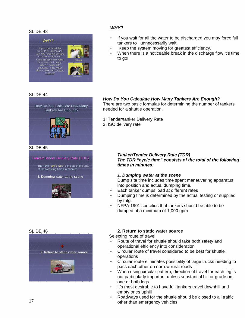
WHY? • If you wait for all the water to be discharged you may force full
tankers to unnecessarily wait. • Keep the system moving for greatest efficiency. • When there is a noticeable break in the discharge flow it’s time
to go!
How Do You Calculate How Many Tankers Are Enough? There are two basic formulas for determining the number of tankers needed for a shuttle operation. 1: Tender/tanker Delivery Rate 2. ISO delivery rate
Tanker/Tender Delivery Rate (TDR) The TDR “cycle time” consists of the total of the following times in minutes: 1. Dumping water at the scene Dump site time includes time spent maneuvering apparatus into position and actual dumping time.
• Each tanker dumps load at different rates • Dumping time is determined by the actual testing or supplied
by mfg. • NFPA 1901 specifies that tankers should be able to be
dumped at a minimum of 1,000 gpm 2. Return to static water source
Selecting route of travel • Route of travel for shuttle should take both safety and
operational efficiency into consideration • Circular route of travel considered to be best for shuttle
operations • Circular route eliminates possibility of large trucks needing to
pass each other on narrow rural roads • When using circular pattern, direction of travel for each leg is
not particularly important unless substantial hill or grade on one or both legs
• It’s most desirable to have full tankers travel downhill and empty ones uphill
• Roadways used for the shuttle should be closed to all traffic other than emergency vehicles

18
SLIDE 47
4141
++3. Fill the tanker3. Fill the tanker
SLIDE 48
4848
4. Return to the scene4. Return to the scene
++
SLIDE 49
(con’t)
OTHER SAFETY CONCERNS: • Narrow roads require tight maneuvering, increasing the
potential for tires going off roadway & causing accident or getting stuck.
• Long driveways often cause maneuvering problems, such as need to back down the driveway, potentially meeting other shuttles on driveway. For a safer water transfer, a LDH supply line should be utilized to pump the water up the driveway from the supply tanker to the primary pumper.
• Blind curves & winding roads decrease ability to see oncoming traffic or cross traffic.
• Hills can affect braking ability and wear on vehicle 3. Fill the tanker If some tankers have 2-1/2” intakes and others use LDH intakes, it will be necessary to lay out hose that can be easily connected to either.
• Best method is to lay LDH to area convenient for loading tankers
• Connect manifold to LDH line • One LDH and 2, 3-inch lines connected from manifold. • Manifold must be monitored and operated by a firefighter. • May use a LDH reducer to the 2-1/2” tanker intake
TOP FILL METHOD:
• In some FD’s, the tanker fill is through the fill or vent opening on top of the apparatus.
• Filling is accomplished using either fixed or portable filling equipment
• Fill pipes can be made from PVC or lightweight material. • If fixed equipment is used you must remember that the fill site
is limited by location size. • Try to avoid having people climb up onto the tanker each time
it is there (safety) 4. RETURN TO THE SCENE The same precautions mentioned in the travel time to the fill site apply to the return to the incident site.

19
4949
Tanker/Tender Delivery Rate (TDR) Tanker/Tender Delivery Rate (TDR) formulaformula
TDR in GPM= TDR in GPM= Tank sizeTank size--10%10%Cycle TimeCycle Time
GPM= GPM= 30003000--30030012 minutes12 minutes
NOTE: ISO deducts 10% from the tanker to cover incomplete fillinNOTE: ISO deducts 10% from the tanker to cover incomplete filling & spillage g & spillage
GPM= GPM= 2700270012 12
GPM= GPM= 225225
Formula #1
SLIDE 50
5050
Tanker size= Tanker size= 3,000 gallons 3,000 gallons –– 10%10%Cycle time= Cycle time= 12 minutes12 minutes
2700 2700 ÷÷ 12 = 225 GPM12 = 225 GPM
650 650 ÷÷ 225= 225= 3 tankers required3 tankers required
EXAMPLE:EXAMPLE:
You need to supply 650 GPM at an incident You need to supply 650 GPM at an incident scenescene
SLIDE 51
5151
ISO Delivery formulaISO Delivery formula
Another way of computing the cycle time is Another way of computing the cycle time is to use the ISO method:to use the ISO method:
Fill time + dump time + travel timeFill time + dump time + travel time
ISO deducts 10% from the tanker to cover ISO deducts 10% from the tanker to cover incomplete filling, spillage and incomplete incomplete filling, spillage and incomplete
dumping.dumping.
Formula #2
SLIDE 52
5252
ISO Travel Time formulaISO Travel Time formula
D x 1.7 +.65= Travel timeD x 1.7 +.65= Travel time
DD = total distance= total distance1.71.7 = factor for 35 MPH (60 seconds = factor for 35 MPH (60 seconds ÷÷ 35 mph)35 mph)..6565 = accelerating & braking time= accelerating & braking time
If the round trip distance is If the round trip distance is 22 miles, the formula is:miles, the formula is:22 X X 1.7 1.7 + + .65.65 = = 4.05 minutes4.05 minutes
Tanker/Tender Delivery Rate (TDR) formula TDR in GPM = Tank size minus 10% divided by the cycle time. Refer to PowerPoint slide and demonstrate how to do the calculations EXAMPLE: Refer to PowerPoint slide to demonstrate how to do the calculations You need to supply 650 GPM at an incident scene Tanker size= 3,000 gallons – 10% Cycle time= 12 minutes 2700 ÷ 12 = 225 GPM 650 ÷ 225= 3 tankers required ISO DELIVERY FORMULA: Another way of computing the cycle time is to use the ISO method: Fill time + dump time + travel time ISO deducts 10% from the tanker to cover incomplete filling, spillage and incomplete dumping. ISO TRAVEL TIME FORMULA D x 1.7 +.65= Travel time D = total distance 1.7 = factor for 35 MPH (60 seconds ÷ 35 mph) .65 = accelerating & braking time If the round trip distance is 2 miles, the formula is: 2 X 1.7 + .65 = 4.05 minutes

20
SLIDE 53
5353
Calculating TDR using ISOCalculating TDR using ISO
Fill time + Dump time + Travel Time= Total timeFill time + Dump time + Travel Time= Total time3 min. + 3 min. + 4.05 min. = 10.05 min.3 min. + 3 min. + 4.05 min. = 10.05 min.
Tank sizeTank size ÷÷ Total time = Total GPMTotal time = Total GPM3,5003,500--10% 10% ÷÷ 10.05 = 31310.05 = 313
In this scenario the tanker will deliver 18,780 In this scenario the tanker will deliver 18,780 gallons per HOUR (313 x 60)gallons per HOUR (313 x 60)
SLIDE 54
5454
Tanker Dump CapabilityTanker Dump Capability((This is a PREThis is a PRE--INCIDENT calculation)INCIDENT calculation)
One of the most accurate ways to measure the One of the most accurate ways to measure the amount of water that a tanker will normally dump amount of water that a tanker will normally dump can assist with calculating the tanker efficiency.can assist with calculating the tanker efficiency.
1.1. Weigh tanker on truck scale when completely full Weigh tanker on truck scale when completely full and again after the tank dump.and again after the tank dump.
2.2. Difference in weight accounts for water actually Difference in weight accounts for water actually dumped.dumped.
3.3. Divide this difference by 8.34 (pounds per gallon)Divide this difference by 8.34 (pounds per gallon)4.4. This will determine the actual gallons in the tankThis will determine the actual gallons in the tank
SLIDE 55
5555
EXAMPLE:EXAMPLE:
You want to determine how much water was You want to determine how much water was actually dumped from a 2,000 gallon tanker with actually dumped from a 2,000 gallon tanker with a weight difference of 14,500 after the dump.a weight difference of 14,500 after the dump.
14,500 14,500 ÷÷ 8.34= 1,739 gallons dumped8.34= 1,739 gallons dumped(8.34= pounds per gallon of wat(8.34= pounds per gallon of water)er)
This will assist you when calculating the dumping This will assist you when calculating the dumping capability of this particular tanker for future capability of this particular tanker for future
incidents.incidents.
SLIDE 56
5757
Fill Site SetupFill Site Setup
CALCULATING TDR USING ISO Fill time + Dump time + Travel Time= Total time 3 min. + 3 min. + 4.05 min. = 10.05 min. Tank size ÷ Total time = Total GPM 3,500-10% ÷ 10.05 = 313 In this scenario the tanker will deliver 18,780 gallons per HOUR (313 x 60) Tanker Dump Capability (This is a PRE-INCIDENT calculation) One of the most accurate ways to measure the amount of water that a tanker will normally dump can assist with calculating the tanker efficiency.
1. Weigh tanker on truck scale when completely full and again after the tank dump.
2. Difference in weight accounts for water actually dumped. 3. Divide this difference by 8.34 (pounds per gallon) 4. This will determine the actual gallons in the tank
EXAMPLE: You want to determine how much water was actually dumped from a 2,000 gallon tanker with a weight difference of 14,500 after the dump.
14,500 ÷ 8.34= 1,739 gallons dumped (8.34= pounds per gallon of water) This will assist you when calculating the dumping capability of this particular tanker for future incidents. FILL SITE SETUP

21
SLIDE 57
5151
The best fill site is not necessarily
the closest site
3 MILES
2 MILES
SLIDE 58
5050
When possible, a 1,000+ GPM water source is preferred.
versus
SLIDE 59
5353
Establishing the Fill SiteEstablishing the Fill Site
An open area to maneuver the tanker is preferred. If maneuvering is unavoidable, it’s always easier to maneuver an empty tanker than a full one.
THE BEST SITE IS NOT NECESSARILY THE CLOSEST SITE
• For reasons of travel safety or water flow requirements, sometimes it is better to establish a fill site at a location somewhat further from the dump site than the closest source.
• The department should have knowledge of adequate fill sites
within their coverage area. A small stream one mile from the scene may be inadequate versus an easily accessible lake 2 miles away.
WHEN POSSIBLE, A 1,000+ GPM WATER SOURCE IS PREFERRED If the water supply at a single site is limited, two or more fill sites may need to be established to meet water flow requirements. ESTABLISHING THE FILL SITE
• An open area to maneuver the tanker is preferred. If maneuvering is unavoidable, it’s always easier to maneuver an empty tanker than a full one
• Anytime that the tanker is required to maneuver in a tight area, such as backing up to the portable tank, a firefighter must be assigned to stand to the left rear of the vehicle to assist with backing.
• Firefighters should have a highly visible traffic vest that meets new DOT guidelines (5 point break-away style)

22
SLIDE 60
6060
In a large shuttle operation, multiple fill sites are more advantageous than one crowded one
SLIDE 61
5353
Dumpsite SetupDumpsite Setup
SLIDE 62
5656
It must be easily accessible for tankers It must be easily accessible for tankers to dump waterto dump water
In a large shuttle operation, multiple fill sites are more advantageous than one crowded one For the safety of everyone involved, along with increased efficiency, multiple fill sites may be needed. If this is deemed necessary, consideration must be given to avoiding tankers meeting head-on on narrow rural roads. DUMPSITE SETUP
The attack pumper, sitting along side of a portable tank, takes up quite a bit of room. Make sure that you don’t lock the scene from incoming apparatus that will be needed at the incident. If you have very limited area to operate from, consider the 3 pumper method for a water shuttle. IT MUST BE EASILY ACCESSIBLE FOR TANKERS TO DUMP WATER
• Location should be in close proximity to incident scene.
• The best dump/fill sites are those in which the tanker
can be driven straight in from one direction, fill or dump, and proceed straight out the other end. Tankers with side dumps will greatly benefit from a straight-in approach
• Pulling up alongside a tank is safer than backing up.
It also allows for reduced dumping time by allowing the driver to quickly position the tanker. Side discharges help to facilitate dumping

23
SLIDE 63
5656
It must be large enough to support the It must be large enough to support the incident needsincident needs
SLIDE 64
6464
It cannot interfere with fireground It cannot interfere with fireground operations!operations!
Remember, the tankers won’t be the only Remember, the tankers won’t be the only fire apparatus on the scene.fire apparatus on the scene.
SLIDE 65
5959
It should be positioned away from It should be positioned away from other traffic. other traffic.
IT MUST BE LARGE ENOUGH TO SUPPORT THE INCIDENT NEEDS If you cannot meet the flow requirements for an incident, it’s time to ask for more resources!
• More portable tanks will allow for more dumping capacity.
• More tankers will allow for a better water supply. • When determining where to set up the dump site,
consideration should be given to possible expansion of the site as needs arise.
IT CANNOT INTERFERE WITH FIREGROUND OPERATIONS Remember, the tankers won’t be the only fire apparatus on the scene. The attack pumper, sitting along side of a portable tank, takes up quite a bit of room. Make sure that you don’t lock the scene from incoming apparatus that will be needed at the incident. If you have very limited area to operate from, consider the 3 pumper method for a water shuttle. IT SHOULD BE POSITIONED AWAY FROM OTHER TRAFFIC. The location must be shut down to normal traffic. Only emergency vehicles should be allowed in.

24
SLIDE 66
5858
Traffic ControlTraffic Control
TANKERS ONE WAY
SLIDE 67
6767
Setting Up Portable TanksSetting Up Portable Tanks
Self supporting
Foldout frame
SLIDE 68
6262
Step 1Step 1
Remove the portable tank from the Remove the portable tank from the apparatusapparatus
TRAFFIC CONTROL Approach and departure by a tanker should be in the same direction to avoid conflicts. Tankers approaching the dump or fill site from opposing directions can hinder the efficiency, along with increasing the potential for accidents. Setting Up Portable Tanks Efficiency setting up the portable tank(s) is critical to insure adequate water supplies at the incident scene. The attack engine will quickly deplete itself of its on-board water supply during the initial attack phase. The priority is to establish a water supply for the attack pumper as quickly as possible so that firefighting operations and protection of firefighters won’t be interrupted. Portable tanks range between 1,000 to 3,000 gallons. There are 2 general sizes:
• Self supporting: reinforced sides that are rigid enough to support water
• Foldout frame: Most common. Flexible material supported by steel frame.
STEP 1: REMOVE THE PORTABLE TANK FROM THE APPARATUS
• Often the portable tank is carried on the tanker. • It will be removed either manually or through hydraulic means.

25
SLIDE 69
7070
Step 2Step 2
Place the portable tank next to the Place the portable tank next to the pumperpumper
SLIDE 70
6464
Step 3Step 3
The strainer is placed on the end of the The strainer is placed on the end of the hard suction hosehard suction hose
Floating strainer Barrel strainer High volume strainer
7272
Drafting Hint:Drafting Hint:
++
Placing a volleyball into the dump tank can act as a seal for the swirling vortex near the strainer as the water level nears the bottom of the tank. This will help to avoid losing
the pump prime due to air induction
STEP 2: PLACE THE PORTABLE TANK NEXT TO THE DRAFT PUMPER
• The portable tank must be located close to the drafting pumper for ease of setup and operation.
• The portable tank drain sleeve should be pointing downhill. When fire operations are ended it’ll be easier to drain the tank of unused water if gravity can be brought into play.
• Note that in this photo a tarp was laid out to protect the tank from
damage from roadway debris STEP 3: THE STRAINER IS PLACED ON THE END OF THE HARD SUCTION HOSE
• Floating strainer: used in drafting operations to avoid pulling debris into the hose.
• Barrel strainer: This can be used either at the water source or in a portable tank. It prevents large debris from being pulled into the hose. A rope should be attached to the ring at the end of the strainer for ease of movement or repositioning of the suction hose. Keep in mind that this type of strainer leaves 6” to 8” of unusable water in the tank.
• High volume strainer: This is used in the portable tank by the drafting pumper. The bottom opening pulls water from the very bottom of the portable tank, increasing the amount of available water in the tank.
• It is important to remember that once you begin using any of these
strainers that the opening remains below the water level or the draft prime will be lost.
• DRAFTING HINT: A swirling effect is usually created using a basket or barrel strainer. This swirling effect can allow air to enter your suction hose, often resulting in loss of the pump prime. This can occur even if there is more than a foot of water over the strainer. To prevent this, a volleyball or tetherball can be placed into the dump tank. The ball will float to the swirl and “seal” it so that air cannot get into the hose, thus avoiding the loss of the pump prime!

26
SLIDE 71
6565
Step 4Step 4
Suction hose is connected to the Suction hose is connected to the pumperpumper
SLIDE 72
7272
The portable tank is filled from a tankerThe portable tank is filled from a tanker
Step 5Step 5
SLIDE 73
7373
The pumper can now begin drafting The pumper can now begin drafting operations from the portable tankoperations from the portable tank
Step 6Step 6
STEP 4: Suction hose is connected to the pumper • The hard suction hose must be air-tight at all
connections or the priming of the pump will not be able to be accomplished.
• Suction hose couplings should never be hit with a metal hammer to tighten them. Rubber mallets can assist in the tightening task.
• Setup a return line (suggest 10 feet of 2 ½” hard suction) from the pumper back to the tank for circulation of water when the fire flow is minimal to keep the pump cool.
STEP 5: THE PORTABLE TANK IS FILLED FROM A TANKER
• Some tankers have extensions that can be attached to the dump to direct water into a portable tank. In this photo the tanker has been turned into a “side discharge” tanker from a “rear discharge” by the simple addition of the extension.
• The side discharge allows for quicker unloading by eliminating the need to back up to the portable tank. It also reduces the chance for injury to firefighters by eliminating the backing up requirement.
STEP 6: THE PUMPER CAN NOW BEGIN DRAFTING OPERATIONS FROM THE PORTABLE TANK It is important to remember that valves should be opened and closed slowly. If this is NOT done the water hammer effect can damage every apparatus connected to the water supply system. Policy decision: Some FD’s encourage the attack pumper to “steal” some of the portable tank water during drafting operations. They will crack open the tank fill so that some of the water can be use to refill the depleted tank on the pumper. This proves to be a benefit if the tankers cannot adequately keep the portable tank filled and the portable tank runs out of water between dumps. The pump operator can then use his “stolen” tank water to insure a constant water supply to firefighters during the dumping cycle.

27
SLIDE 74
6868
Water transfer between tanksWater transfer between tanks
SLIDE 75
6969
Determining Water NeedsDetermining Water Needs~ A Quick Review For Firefighters ~~ A Quick Review For Firefighters ~
SLIDE 76
7676
Width=60’Width=60’Length=52’Length=52’
NFA Formula for Fire Flow =Length X Width ÷ 3 X (Number of Floors)
Using this floor plan the calculations are:
60’ X 52’ ÷ 3 x 1 = 1040 GPMIf this is a 2 floor structure:
60’ X 52’ ÷ 3 x 2 = 2080 GPM
Single story structure % involvement:
100% = 1040 GPM
50% = 520 GPM
25% = 260 GPM
Water transfer between tanks
1. The primary draft tank is filled first so that drafting can begin immediately
2. A second tank is placed next to the draft tank and is filled
3. A hard suction hose is draped over the adjoining sides
4. A hose flowing water is inserted into the hard suction hose to create a siphon
5. The hose used to create the siphon should be left in place so it can be quickly utilized if the siphon prime is lost. The siphon hose placed in the suction hose should be secured with a rope to the other end (running the rope through the suction hose, then tying it to the outside of the hard suction). This will prevent it from slipping out and will avoid having to hold onto it.
6. Several manufacturers make a low level water transfer device that screws onto the hard suction hose. It is just a low level strainer with a 1 ½ inch female fitting and a jet siphon built into it.
Determining Water Needs ~ A Quick Review For Firefighters ~ NFA Formula for Fire Flow = Length X Width ÷ 3 X (Number of Floors)

28
SLIDE 77
7777
Calculating Flow With ExposuresCalculating Flow With ExposuresEach exposure = 25% of GPM of primary structureEach exposure = 25% of GPM of primary structure
60 X 52 ÷ 3 x 1 = 1040 GPM
(3120 ÷ 3 X 1 = 1040)
2 Exposures: 1040 GPM X (25% X 2) = 520 GPM
(1040 x 25% = 260 GPM x 2 exposures= 520gpm)
Total Fire Flow required = 1560 GPM (1040 + 520)
(for 100% involvement of the original structure)
Exposure #2Exposure #1
SLIDE 78
8080
Table Top ExerciseTable Top Exercise
SLIDE 79
7979
MUTUAL AID TANKER SHUTTLE TABLETOP EXERCISE
Your department has been dispatched to a residential structure fire in a rural area. The first apparatus on the scene reports a structure
50% involved on both floors, and has exposures on either side. The involved 2 story structure measures 60 feet by 40 feet. You must determine the total GPM needed to suppress this fire and
protect the exposures. Determine the number of tankers required to meet the GPM needed for this fire.
Assume that EACH tanker has a 2,000 gallon tank and you’ve already determined the “cycle time” at 12 minutes per tanker.
Calculating Flow With Exposures Each exposure = 25% of GPM of primary structure 60 X 52 ÷ 3 x 1(exposure) = 1040 GPM (3120 ÷ 3 X 1 = 1040) 2 Exposures: 1040 GPM X (25% X 2) = 520 GPM (1040 x 25% = 260 GPM x 2 exposures= 520gpm) Total Fire Flow required = 1560 GPM (1040 primary structure + 520 exposures) (for 100% involvement of the original structure) TABLE TOP EXERCISE Break the classroom into 4-5 students per group and have each group calculate the number of tankers needed for the below scenario MUTUAL AID TANKER SHUTTLE TABLETOP EXERCISE Your department has been dispatched to a residential structure fire in a rural area. The first apparatus on the scene reports a structure 50% involved on both floors, and has exposures on either side. The involved 2 story structure measures 60 feet by 40 feet. You must determine the total GPM needed to suppress this fire and protect the exposures. Determine the number of tankers required to meet the GPM needed for this fire. Assume that EACH tanker has a 2,000 gallon tank and you’ve already determined the “cycle time” at 12 minutes per tanker.

29
SLIDE 80
8080
Do not proceed until you have the Do not proceed until you have the solution to the previous scenariosolution to the previous scenario
SLIDE 81
8181
GPM NEEDED=
60’ X 40’= 2400 2400 ÷ 3= 800 gpm
800 X 2 story = 1600 gpm
50% structure involvement: 1600 ÷ 2 = 800 gpm
800 X 25%= 200 X 2 exposures= 400 gpm
800 gpm + 400 gpm = 1200 gpm
TANKER SIZE = 2,000 GALLONS EACH2000 – 10% = 1800 1800 ÷ 12 min. cycle time= 150 gpm
1200 ÷ 150 = 8 TANKERS REQUIRED
SLIDE 82
8383
BeforeBefore you begin the practical you begin the practical portion of this course…..portion of this course…..
Please complete the written examPlease complete the written exam
Proper TOG will be worn and all safety practices will be followeProper TOG will be worn and all safety practices will be followedd
AfterAfter you complete the practical you complete the practical portion of this course…..portion of this course…..
Please complete the course evaluation sheetPlease complete the course evaluation sheet
Do not proceed until you have the solution to the previous scenario GPM NEEDED= 60’ X 40’= 2400 2400 ÷ 3= 800 gpm 800 X 2 story = 1600 gpm 50% structure involvement: 1600 ÷ 2 = 800 gpm 800 X 25%= 200 X 2 exposures= 400 gpm 800 gpm + 400 gpm = 1200 gpm TANKER SIZE = 2,000 GALLONS EACH 2000 – 10% = 1800 1800 ÷ 12 min. cycle time= 150 gpm 1200 ÷ 150 = 8 TANKERS REQUIRED Before you begin the practical portion of this course…..
Please complete the written exam Proper TOG will be worn and all safety
practices will be followed
After you complete the practical portion of this course…..
Please complete the course evaluation sheet Filling out the evaluation form AFTER the practical can act as a confirmation that the students have remained for the practical portion of the class. The instructor has final say as to when this should be done.

30
SLIDE 83
8585
Tanker ExerciseTanker Exercise
It’s time to put what you’ve learned into practice!
Tanker Shuttle Practical Exercise The purpose of this 4-hour practical session is to familiarize the students with actual tanker shuttle operations. They will need to setup a portable water dump tank and draft from it. A tanker, or tankers, will be utilized to demonstrate the operations at a dump site; a fill site; and how to time a tanker’s “cycle time”. The students should be split into two groups so that they can participate at both the fill and dump sites. They will be rotated as a group once they have accomplished at least one tanker cycle. EQUIPMENT REQUIRED:
• Minimum of one tanker (two or more is preferred) • Two pumpers capable of drafting (one can be substituted with 2 or more portable
pumps if necessary) • Minimum of one portable tank (two are preferred) • All participants/instructors must be in full TOG (safety must be stressed!)
FILL SITE:
The fill site can use water from any source. If a hydrant is used, it must be at least ½ mile from the dump site. The students will be responsible for setting up a portable tank and then taking it back down during this evolution. If a portable tank is NOT used at the fill site, they must set one up and take it back down during their time at the dump site.
• The location must allow for safe operations. ICS shall be utilized. • It will not interfere with local traffic if at all possible. • All operations will be in a non-emergency mode • One pumper will be assigned to the fill site and configured to supply in-
coming tankers with water. • The students will work under ICS and will setup the fill site to fill incoming
tankers efficiently.

31
DUMP SITE: The dump site will utilize at least one dump tank. The students will be responsible for setting up a portable tank and then taking it back down during the evolution.
• The locations must allow for safe operations. ICS shall be utilized. • It will not interfere with local traffic if at all possible. • One pumper will be assigned as the attack pumper. If this is a two pumper
evolution, this pumper will also be responsible for drafting from the portable tank. • If a third pumper is utilized, the drafting pumper will supply a water supply line to
the attack pumper, which will be located nearby. • The students will calculate the GPM from at least one tanker using the TDR
formula. POSSIBLE ADDITIONS TO THE PRACTICAL EXERCISE: Consider adding the following to the practical exercise if time and equipment allows:
• Set up two fill sites at different locations • Set up two portable tanks at the dump site and create a siphon between the two. • Set up one pumper as an attack pumper. When the signal is given, this pumper
will begin discharging at least 250 GPM. The students must ensure that this discharge is not interrupted at any time. This exercise will challenge the students to incorporate the information obtained during the classroom portion.