music quartet based on a psoc
TRANSCRIPT

Final Degree Project
Bachelor's degree in Industrial Technology
Engineering
Music Quartet based on a PSoC
REPORT
Author: Antonio Martínez García
Director: Manuel Moreno Eguilaz
Submission: January 2017
Escola Tècnica Superior d’Enginyeria Industrial de Barcelona


Music quartet based on a PSoC Page 1
Abstract
This report details the migration process of the Quartet code from a Microchip PIC24
microcontroller, which was previously migrated by Pau Mendieta from a Microchip PIC18
microcontroller, to a CY8CKIT-042-BLE PSoC 4 microcontroller manufactured by Cypress
Semiconductor. It also explains how several improvements, both in sound quality and
program functionality, have been implemented into the final program once the migration was
completed.
The original Quartet code, developed by Victor Timofeev, synthesized 4 different voices
(two guitars, a violin and a bass) coordinated by a conductor task, each of which played
from its own music sheet, which was stored in ROM. The sound samples were generated
using amplitude modulation: the characteristic waveform of the instrument (also stored in
ROM) and its amplitude envelope (generated through software) were multiplied, and later
exported through an 8-bit PWM running at 78 kHz. These could later be played on speakers
with the help of an RC filter.
The project was carried out by continuously testing the software on the actual
microcontroller. Moreover, data was extracted from these tests and compared with the
simulation of Pere Domenech’s PIC18 code. A great use of the example projects provided
by Cypress Semiconductor, which demonstrate the features of the PSoC 4 through simple
applications, has also been made. It was also essential to analyze different signals with an
oscilloscope at the laboratory.
The program obtained after completing the project exports the audio signal through a 16-bit
PWM running at 92 kHz and includes an extra voice (a second violin), more accurate
characteristic waveforms and improved amplitude envelopes, as well as added functionality,
such as an extra octave and a wider note frequency range.
The report first presents the basic operation of the original code, which was carefully studied
at the beginning of the project. Then, it explains how the OS (FreeRTOS) and the program
were migrated, along with the extensive troubleshooting process that followed. Moreover, it
details the improvements that were made once the code worked correctly. Finally,
suggestions are made for future improvements.

Page 2 Report
Contents
ABSTRACT _______________________________________________________ 1
CONTENTS _______________________________________________________ 2
1. GLOSSARY ___________________________________________________ 5
2. PREFACE ____________________________________________________ 6
2.1. Prior works related to this project..............................................................................6
2.2. Motivation ..................................................................................................................7
2.3. Previous requirements ..............................................................................................7
3. INTRODUCTION _______________________________________________ 8
3.1. Objectives .................................................................................................................8
3.2. Scope of the project ..................................................................................................8
4. BASIC QUARTET OPERATION __________________________________ 10
4.1. The Conductor ........................................................................................................10
4.2. The Instruments ......................................................................................................10
4.3. The Synthesizer ......................................................................................................11
4.4. Pulse Width Modulation ..........................................................................................13
5. SOFTWARE MIGRATION _______________________________________ 14
5.1. FreeRTOS migration...............................................................................................14
5.2. FreeRTOS configuration .........................................................................................14
5.2.1. Co-operative scheduler .................................................................................................... 14
5.3. Introducing the TCPWM block ................................................................................15
5.4. Quartet code migration ...........................................................................................16
5.4.1. Changes made to the amplitude modulation .................................................................. 16
5.4.2. Changes made to the PWM ............................................................................................ 17
6. QUARTET TROUBLESHOOTING ________________________________ 18
6.1. Adjusting temp_dac ................................................................................................19
6.2. Increasing clock speed ...........................................................................................20
6.3. Extracting data from the PSoC 4 ............................................................................21
6.4. Comparison between PSoC 4 and PIC18 ..............................................................23
6.4.1. Testing conditions ............................................................................................................ 23
6.4.2. S2.f ................................................................................................................................... 24
6.4.3. Temp1 .............................................................................................................................. 25
6.4.4. S2.t ................................................................................................................................... 25
6.4.5. Temp2 .............................................................................................................................. 26
6.4.6. Temp_dac ........................................................................................................................ 27

Music quartet based on a PSoC Page 3
6.4.7. Comparison conclusions ................................................................................................. 27
6.5. Temporal analysis .................................................................................................. 28
6.5.1. PWM frequency verification ............................................................................................ 28
6.5.2. Interrupt frequency .......................................................................................................... 28
6.5.3. Timer implementation...................................................................................................... 29
6.5.4. Interrupt frequency verification ........................................................................................ 30
6.5.5. Tickless idle ..................................................................................................................... 32
6.6. Final corrections ..................................................................................................... 33
6.6.1. PWM block variation ....................................................................................................... 33
6.6.2. Sound quality correction .................................................................................................. 34
7. QUARTET IMPROVEMENTS ___________________________________ 35
7.1. 16-bit PWM ............................................................................................................ 35
7.2. New amplitude envelopes ...................................................................................... 36
7.3. Waveform tables with 128 data points ................................................................... 39
7.3.1. Data interpolation ............................................................................................................ 39
7.3.2. Data reading method ....................................................................................................... 40
7.3.3. Program modifications .................................................................................................... 40
7.4. Waveform tables with 256 data points ................................................................... 41
7.4.1. Interpolated data .............................................................................................................. 41
7.4.2. Code modifications .......................................................................................................... 43
7.5. Waveform tables with 512 data points ................................................................... 43
7.6. Broadening the note frequency range ................................................................... 44
7.6.1. Duration modifications ..................................................................................................... 44
7.6.2. Change into the integer type ........................................................................................... 44
7.6.3. Command re-structure .................................................................................................... 44
7.7. Adding an extra octave .......................................................................................... 45
7.8. Adding an extra voice ............................................................................................ 46
7.8.1. Notelist and sound channel ............................................................................................. 46
7.8.2. Synthesizer modifications ................................................................................................ 46
7.8.3. FreeRTOS related modifications .................................................................................... 47
8. FINAL QUARTET ANALYSIS ___________________________________ 50
8.1. Resource usage (4 voices) .................................................................................... 50
8.2. Temporal analysis (4 voices) ................................................................................. 50
8.2.1. PWM frequency ............................................................................................................... 50
8.2.2. Interrupt frequency .......................................................................................................... 51
8.2.3. Tempo ............................................................................................................................. 51
8.2.4. Computational effort of synthesizing a sound sample .................................................... 52
8.2.5. Computational effort of adjusting temp_dac ................................................................... 53
8.2.6. Command processing ..................................................................................................... 54
8.3. Resource usage (5 voices) .................................................................................... 55
8.4. Temporal analysis (5 voices) ................................................................................. 55

Page 4 Report
8.4.1. Interrupt duration .............................................................................................................. 55
9. FUTURE IMPROVEMENTS _____________________________________ 56
9.1. Bluetooth .................................................................................................................56
9.2. Utilizing hardware blocks ........................................................................................56
9.3. Adding new instruments .........................................................................................56
9.4. Multiple sound outputs ............................................................................................57
9.5. Widening the range of note durations .....................................................................57
10. PLANNING __________________________________________________ 58
11. BUDGET ____________________________________________________ 59
12. ENVIRONMENTAL IMPACT _____________________________________ 60
CONCLUSION ____________________________________________________ 61
BIBLIOGRAPHY __________________________________________________ 62

Music quartet based on a PSoC Page 5
1. Glossary
BLE: Bluetooth Low Energy
BPM: Beats Per Minute
CAN: Controller Area Network
CPU: Central Processing Unit
DAC: Digital to Analog Converter
IDE: Integrated Developing Environment
ISR: Interrupt Service Routine
LED: Light-Emitting Diode
OS: Operating System
PIC: Peripheral Interface Controller
PSoC: Programmable System on a Chip
PWM: Pulse Width Modulation/Modulator
RC: Resistor-Capacitor
RF: Radio Frequency
ROM: Read-Only Memory
RTOS: Real Time Operating System
SCB: Serial Communication Block
SRAM: Static Random Access Memory
TCPWM: Timer Counter Pulse Width Modulator
UART: Universal Asynchronous Receiver-Transmitter
UDB: Universal Digital Block
USB: Universal Serial Bus

Page 6 Report
2. Preface
2.1. Prior works related to this project
The origin of this project goes back to Victor Timofeev’s usage example of the OSA RTOS
[1]. Timofeev designed a program, which he named “Quartet”, that was able to synthesize a
4-channel melody and export it using an 8-bit PWM running at 78 kHz so that, with the help
of an RC filter, it could be played on speakers or headphones. The original code was written
for a PIC16 microcontroller and used the OSA RTOS as an operating system.
In 2015 Pere Domenech, a student at ETSEIB (Escola Tècnica Superior d’Enginyeria
Industrial de Barcelona), succeeded in migrating Timofeev’s code so that it could be
executed using a PIC18 microcontroller [2]. He chose this microcontroller in particular
because it is widely available at the Department of Electronics at said university.
Two years later another student, Pau Mendieta, migrated Pere Domenech’s code so that a
PIC24 could run it [3]. This meant a change from an 8-bit CPU to a 16-bit CPU and,
therefore, he expected to improve the sound quality by increasing the PWM resolution. In
the end, however, only a 9-bit PWM running at 31.25 kHz was achieved and, thus, the audio
quality did not improve significantly. He also made the necessary changes so that the code
could run on FreeRTOS [4], a more universal operating system which is easier to migrate.
Other related projects include Juan Gallostra’s RF Music Festival: orquesta basada en
microcontroladores PIC18 y RF [5] and Joan Calvet’s CAN Music Festival: Orquestra
Basada en Microcontroladors PIC18 i un bus CAN [6]. The former designed a musical
orchestra where each instrument was individually synthesized by four different PIC18
microcontrollers and the conductor sent commands or notes to each instrument through RF.
The latter pursued the same objective, but using a CAN bus instead of RF as a means of
communication.

Music quartet based on a PSoC Page 7
2.2. Motivation
The reasons that justified the creation of this project are the following:
Learn how to program a microcontroller in C language.
Learn how to use a PSoC and get familiarized with its specific IDE.
Understand how a RTOS, more specifically FreeRTOS, works.
Apply the knowledge and skills learned in an engineering degree to a more practical
case.
Upgrade an existing code so that it produces an improved result.
Learn a method of synthesizing music.
Deepen the personal knowledge in the fields of electronics, programming and
music.
2.3. Previous requirements
Since the original code is written in C language, it is essential to have a certain degree of
understanding of this programming language before the actual project can begin. In this
case, an introductory tutorial was consulted [7]. Knowing the basics of digital electronics is
also necessary.
Moreover, one has to familiarize themselves with the PSoC specific IDE, PSoC Creator 4.1
[8], in order to develop the code, transfer it to the processor and manage the chip’s
configurable hardware blocks. With regard to these components, some of their datasheets
have to be studied carefully, namely the PWM [9], TCPWM [10], SCB [11], Clock [12],
Interrupt [13] and Pins [14] components.
In addition, it is important to study the pin distribution on the kit [15] whenever cable
connections have to be made and to understand the fundamental behavior and
characteristics of the FreeRTOS operating system [16].

Page 8 Report
3. Introduction
3.1. Objectives
This is the first time a PSoC is used in the Department of Electronic Engineering at ETSEIB.
Therefore, the first objective of this project is to learn how to use a CY8CKIT-042 PSoC 4
Pioneer Kit and acquaint oneself with its features.
The second aim is to adapt both the operating system and the Quartet code so that the
PSoC 4 is able to run them correctly. Since FreeRTOS is compatible with this
microcontroller, this migration should not be excessively difficult.
Another important objective is to make use of the PSoC 4’s advantages over the other
microcontrollers to improve the resulting sound quality. This can be done in numerous ways,
as it will be explained further on, but the most important one is to increase the PWM bit
resolution.
Lastly, another important feature of the PSoC is that it includes configurable analog and
digital blocks along with the CPU core. It was thus initially thought that some of the
operations that were originally implemented through software could be accomplished with
hardware instead, hence relieving some of the CPU’s computational effort. However, it was
concluded that the blocks required to do this were only available in a more complex version
of the PSoC used.
3.2. Scope of the project
A significant amount of time in this project will be devoted to learning about the C
programming language, FreeRTOS, the features of the PSoC, etc. It will also be essential to
study carefully and understand the original Quartet code in order to migrate it correctly.
All software modifications will be constantly tested using the corresponding hardware. This
is made possible thanks to the USB connection between the PSoC 4 and a PC, which
allows a fast debugging, testing and analysis of the code. As a downside, unlike the PIC
microcontrollers, the code cannot be simulated, it must be always tested on the actual chip.
Moreover, modifications of the original Quartet code will be considered, especially those that
help improve the sound quality of the synthesized instruments. Nevertheless, these will only
be studied once the migration process has been completed.

Music quartet based on a PSoC Page 9
The project will conclude once the code has been correctly migrated and the sound quality
of the final result is empirically verified to be superior to the older projects mentioned
beforehand. Finally, further improvements will be suggested for future projects.

Page 10 Report
4. Basic Quartet Operation
Before introducing the migration process, it is essential to understand the basic operation of
the Quartet program.
4.1. The Conductor
The conductor is a task whose purpose is to coordinate all instruments and set the tempo of
the song. To do so, the conductor sends a semaphore to each instrument for every
command or note in their note list and then creates a delay that sets the tempo.
4.2. The Instruments
There are a total of 4 voices (a violin, two guitars and a bass) each of which is represented
by a task. These tasks read and execute every command/note when the conductor tells
them to.
Every voice has a note list stored in ROM (located in the bach1067.h file), where every
element is either a command (pause, set octave, repeat, etc) or a musical note. In the
sinus.h file there is a table (also stored in ROM) for every instrument that contains one
digitized period of its characteristic waveform (see Fig. 4.1).
Figure 4.1: Violin characteristic waveform. Source: Victor Timofeev’s data in sinus.h

Music quartet based on a PSoC Page 11
4.3. The Synthesizer
The sound synthesizing is done during processor interrupts using a technique known as
amplitude modulation synthesis (see Fig. 4.2). It consists in multiplying two signals: the
modulator signal and the carrier signal. In this case, the carrier signal is a periodical
repetition of the instrument’s characteristic waveform (see Fig. 4.3) and the modulator signal
is the instrument’s envelope (see Fig. 4.4). This is done to simulate the natural evolution of
sound. In the original code, this multiplication was done through a macro called MUL(),
which was written in assembly code so as to speed up calculations.
Once every sample for each voice is generated, they are added and the resulting value is
divided by 4.
Figure 4.2: Amplitude modulation synthesis conceptual diagram. Source: [2]
Modulator Signal
Carrier Signal
Output Signal

Page 12 Report
Figure 4.3: Violin carrier signal. Source: Victor Timofeev’s data in sinus.h
Figure 4.4: Violin envelope. Source: Victor Timofeev’s original Quartet code

Music quartet based on a PSoC Page 13
4.4. Pulse Width Modulation
Once the synthesizer has generated the output signal, this information is stored and sent
within the width of a pulse (see Fig. 4.5). This is known as pulse width modulation. Finally,
the resulting PWM signal passes through a low-pass filter, which eliminates the low voltage
fraction of the signal, and thus the waveform is recovered and reproduced through
speakers.
Figure 4.5: Example of information being stored and sent using PWM. Source: own.

Page 14 Report
5. Software migration
5.1. FreeRTOS migration
The migration process began by testing an example project provided by Cypress
Semiconductor in which FreeRTOS was specifically implemented for the PSoC 4 BLE [17].
The project was built using PSoC Creator 4.1 [8].
This example basically detects when the SW2 switch or the CapSense Slider are pressed
and sends a message through one UART accordingly. Once tested correctly it was possible
to move on to the configuration of the OS.
5.2. FreeRTOS configuration
For the Quartet code to work correctly it is necessary to change some parameters inside the
FreeRTOS configuration. This is done by editing the FreeRTOSConfig.h header file. Apart
from disabling pre-emption (see section 5.2.1), at first all other options were left at their
default setting.
5.2.1. Co-operative scheduler
FreeRTOS allows the pre-emption of tasks, which means that during a tick interrupt (the
OS’s own software-generated interrupt) a higher priority task can force the running task out
of running state, replacing it.
In case of the Quartet code, a context switch (changing which task is running) only happens
when the instruments enter the blocked state to wait for the conductor to give a semaphore
to them. Therefore, the co-operative task scheduler was chosen, which is equivalent to
disabling pre-emption.

Music quartet based on a PSoC Page 15
5.3. Introducing the TCPWM block
The next logical step in the migration process is to test the PSoC 4’s TCPWM block and
understand how it works. In order to do this, a TCPWM example provided by Cypress
Semiconductor was consulted [18].
In this example project, the brightness of a LED is controlled using the TCPWM block. Once
it was successfully tested in separate, all necessary code and configuration was then moved
to the FreeRTOS example to check if both projects were compatible. More specifically, it
was necessary to:
- Replace all previously existing blocks in the TopDesign.cysch file with the TCPWM
block (see Fig. 5.2).
- Enable the interrupt component linked to the TCPWM block (TC_ISR). This is done
using the following command in the main() function:
TC_ISR_StartEx(InterruptHandler);
- Start the TCPWM component and configure its parameters. This is also done in the
main() function, even though the latter can also be done by directly editing the
block’s properties:
PWM_Start();
PWM_WritePeriod(65300u);
- Edit the ISR function so that it handles the TC_ISR interrupt (see Fig. 5.1).
- Remove unnecessary code from the first example.
Figure 5.1: ISR function that handles the TCPWM interrupt. Source: [18]

Page 16 Report
Figure 5.2: TCPWM block, located in the TopDesign.cysch file, which controls the brightness of a green
LED. Source: [18]
After completing these steps, the TCPWM example worked as expected inside the
FreeRTOS project. Now that the operating system’s functions were available and the
TCPWM block was implemented, all in the same project, it was possible to proceed to the
migration of the actual Quartet code.
5.4. Quartet code migration
The first step in the code migration was to copy all Quartet-specific files (sinus.h,
bach1067.h and elochka.h) into the project’s folder. After doing so, Pau Mendieta’s code [3]
had to be implemented into the project’s main.c file. Nevertheless, some modifications were
still necessary.
5.4.1. Changes made to the amplitude modulation
As explained in the previous chapter, the final step in the synthesizing process is to multiply
two signals, which was originally done using assembly language to multiply two variables.
Since migrating this piece of code would not be trivial (the assembly language would be
drastically different) and the PSoC 4’s processor is more powerful than the PIC24’s, this
operation was implemented as a simple product between two variables in C language,
which is more costly (computationally).

Music quartet based on a PSoC Page 17
5.4.2. Changes made to the PWM
All of the code related to the sound synthesizing had to be introduced into the function that
handles the interrupts while respecting the structure seen in section 5.3 (see Fig. 5.1). The
main difference is that the interrupt has to be cleared at the start of the function and that the
pulse width is modulated with the PWM_WriteCompare(temp_dac) command, where
temp_dac is the variable that holds the final synthesized sample of all 4 voices.
It is also important to fit the period of the PWM so that its frequency matches the desired
value. In order to achieve a PWM frequency of 78 kHz while using a 24 MHz clock, the
period has to be 300 (see calculation below).

Page 18 Report
6. Quartet troubleshooting
The aim of the migration process described in the previous chapter was to achieve the
same acoustic result with the PSoC 4 as the one obtained with the PIC microcontrollers.
The migrated program did produce sound, but it was significantly different than what was
expected. The main issues were:
- The sound was highly saturated.
- The notes played by the program were of a much higher frequency than they should
be.
- The melody could only be distinguished when playing one instrument at a time. If
two or more instruments were played simultaneously they fell out of synchronization
and the sound became distorted.
- The tempo was far slower than the original.
- The sound had an overall poor quality.
In this chapter, the process of detecting and solving the mistakes that caused these faults
will be explained in detail. This has been the most challenging and time-consuming part of
the project. Hence, to simplify it, several characteristics of the resulting sound (listed below)
have been evaluated for every possible fix made to the project, in accordance with the
legend presented in table 6.1.
- Clarity: A highly saturated audio signal has a loud cracking sound added to it
(similar to white noise). This makes it bothersome to listen to and sometimes even
makes it difficult to identify the melody that is being played. High clarity will imply little
saturation and vice versa.
- Accuracy of note frequency: Musical notes have a characteristic frequency.
Therefore, a synthesizer that works correctly should generate an audio signal with
the frequency of the desired note.
- Quality: This is a more subjective parameter. Higher quality here will imply a more
detailed and realistic sound.
- Correct interaction between instruments: Troubleshooting is made easier by
analyzing a single voice, but it is also important to check that the sum of all 4 voices
plays correctly.

Music quartet based on a PSoC Page 19
Symbol Meaning
+ Slight improvement
++ Significant improvement
+++ Critical improvement
/ No difference
- Slight worsening
-- Significant worsening
--- Critical worsening
? Not tested
Table 6.1: Legend of the symbols used to describe the improvement/worsening of the audio result
Evaluation tables are always relative to the best configuration that has been found at a
particular point. Obviously, changes that have a positive effect on the result are kept and
those that do not are discarded.
6.1. Adjusting temp_dac
At first, it was thought that temp_dac, the variable that holds the final synthesized sample,
was not properly adjusted to the range of values accepted by the PWM. Since the PWM
period was set to 300, any temp_dac value outside the range of 0-300 would produce
unexpected results.
In the original code, once all of the 4 voices were added the result was divided by 4 and,
later, an offset of 128 was added. This last operation was done because the waveform
tables include negative values. However, since the multiplication operation used in this case
is slightly different, the values produced by the migrated code were of a higher order, and
thus the variable had to be divided by a higher number.
Several combinations of divisor and offset were tested and evaluated empirically. With a
single active voice, the best result was achieved by dividing by 512 (shifting 9 bits to the
right) and adding an offset of 220. The sound became slightly less saturated, but most of
the issues persisted (see table 6.2). It was therefore reasonable to assume that there was a
more serious problem with the migrated code that remained undetected and was

Page 20 Report
responsible for the poor quality of the result.
Clarity +
Accuracy /
Quality /
Correct interaction ?
Table 6.2: Sound evaluation after adjusting the temp_dac variable
6.2. Increasing clock speed
Before starting a more detailed analysis of the migrated code’s behavior, it was decided that
it would be interesting to increase the frequency of the clock that controls the TCPWM
block. Until now, it had been running at the same frequency as the external clock
(EXTCLK), 24 MHz.
However, the TCPWM block allows clocks to operate up to a maximum of 48 MHz [10].
Choosing this clock speed means that, if the same PWM frequency is kept, the PWM period
should now be 600, thus doubling its resolution. In other words, the temp_dac variable
would be able to hold double the amount of different values than it previously could. This
would be equivalent to a 9-bit resolution.
After testing this modification (see recording #1 of the annex), the quality increased slightly
but so did the saturation (see table 6.3). Still, overall this version of the migrated code
sounded better.
Clarity -
Accuracy /
Quality +
Correct interaction ?
Table 6.3: Sound evaluation after increasing the clock speed to 48 MHz

Music quartet based on a PSoC Page 21
6.3. Extracting data from the PSoC 4
Once the PWM resolution and the adjustment of the temp_dac variable were discarded
from being responsible for the major sound issues, a more detailed and comprehensive
analysis of the code’s behavior was deemed necessary.
Up to this point all data had been extracted from the PSoC using breakpoints in PSoC
Creator 4.1. This procedure was enough to check the state of variables at certain points of
execution, but it made saving large amounts of data almost impossible (saving data from
each interrupt, for example). Therefore, it was necessary to find another way to extract
information.
This was done by following an online tutorial that demonstrated how to implement the printf
C function into the PSoC (by default the function compiles without errors, but it does nothing
when called) [19].
First, a UART (SCB mode) block was placed into the TopDesign.cysch file with its standard
configuration. Then, it was assigned to the correct pins, P1.5 and P1.4 (see Fig. 6.1) and,
afterwards, a cable connection was made from P1.5 to P12.6 and from P1.4 to P12.7 (see
Fig. 6.2).
Figure 6.1: Pin assignment of the UART block. Screenshot taken from PSoC Creator 4.1.

Page 22 Report
Figure 6.2: PSoC 4 after making the cable connections for the UART block (green cables). Source: own.
The following steps consisted in increasing the heap size, which is done in the “System” tab
in the .cydwr file, and adding the _write() function to the main.c file (see Fig. 6.3). Moreover,
the UART block has to be started with the UART_Start() command.
Figure 6.3: Additional code necessary for the implementation of the printf function. Source: [19].
Finally, the program PuTTY [20] was installed in order to receive the information that the
PSoC would be transmitting through USB.

Music quartet based on a PSoC Page 23
6.4. Comparison between PSoC 4 and PIC18
In order to discover what had gone wrong in the migration process, a comprehensive
comparison of the PSoC and PIC18’s behavior was done. The PSoC’s data was extracted
using the UART block (as seen in section 6.3), while the PIC18 was analyzed by simulating
Pere Domenech’s code [2] with the use of MPLAB IDE [21].
6.4.1. Testing conditions
Both systems were tested in the following conditions:
- Only one voice (the violin) was playing.
- The only note played was b0 (in Quartet notation) with a base scale of 0 and a
duration of 4.
- The variables whose values were stored for every interrupt were:
S2.f: Works as an index for selecting values from the tables in sinus.h.
temp1: Holds the value read from the tables in sinus.h.
S2.t: Increases by one every 64 interrupts and is used to generate the
amplitude envelope.
temp2: Holds the value of the amplitude envelope.
temp_dac: Holds the value after the amplitude modulation and before it is
adjusted.

Page 24 Report
6.4.2. S2.f
Figure 6.4: Evolution of the S2.f variable during interrupts both in the PSoC and the PIC18. Source: own.
The different evolutions of S2.f shown in Fig. 6.4 are simply due to how each microcontroller
treats the integer type. On the one hand, the PIC18’s integer type is 16 bits and thus has to
reset itself to its lowest value once it reaches its highest permitted value (32768). On the
other hand, the PSoC integer type is 32 bits by default, and allows S2.f to keep increasing.
Since this variable is used as an index, this difference should not be important. In any case,
the code was executed after changing S2.f into int16 in the PSoC to check whether there
was a difference in sound, but there was none.

Music quartet based on a PSoC Page 25
6.4.3. Temp1
Figure 6.5: Evolution of the temp1 variable during interrupts both in the PSoC and the PIC18. Source:
own.
As Fig. 6.5 illustrates, temp1 is read correctly from sinus.h.
6.4.4. S2.t
Figure 6.6: Evolution of the S2.t variable during interrupts both in the PSoC and the PIC18. Source: own.
Fig. 6.6 shows how the behavior of S2.t is the same, with only a phase difference between
them. Several tests were made and this phase difference kept changing. This caused the

Page 26 Report
envelope’s evolution to change, but only slightly, as it will be seen in the following sections.
It was possible to fix this phase difference by modifying the counter that controls the
variable, but it did not have any influence on sound.
6.4.5. Temp2
Figure 6.7: Evolution of the temp2 variable during interrupts both in the PSoC and the PIC18. Source:
own.
Figure 6.8: Temp2 plotted as a function of S2.t both in the PSoC and the PIC18. Source: own.
Temp2 displays the same phase difference due to S2.t (see Fig. 6.7), but the amplitude
envelope is correct, as Fig. 6.8 shows.

Music quartet based on a PSoC Page 27
6.4.6. Temp_dac
Figure 6.9: Evolution of the temp_dac variable during interrupts both in the PSoC and the PIC18. Source:
own.
Here the PSoC’s temp_dac had to be divided by 260 so that it could be compared to the
PIC18. The difference seen in figure 6.9 is again due to the phase difference in S2.t.
Otherwise, the variable evolution is correct.
6.4.7. Comparison conclusions
After comparing the behavior of the most important variables in the synthesizing process, it
was concluded that:
1. The migrated program reads values from the tables in sinus.h correctly.
2. The migrated program creates the amplitude envelopes correctly.
3. The migrated program carries out the modulation operation correctly. There is only a
difference in scale, which forces a different final adjustment of the temp_dac
variable.

Page 28 Report
6.5. Temporal analysis
Since the comparison done in section 6.4 did not reveal any significant differences, it was
decided to carry out a temporal analysis of the PSoC’s behavior.
6.5.1. PWM frequency verification
Figure 6.10: Oscilloscope capture of the PWM signal. Source: own.
The PWM signal was analyzed in the laboratory using an oscilloscope. As seen in Fig. 6.10,
its frequency is correct: 78 kHz.
6.5.2. Interrupt frequency
Here one of the critical differences between the original and migrated programs was
detected. Since the interrupt component in the PSoC had been linked to the TCPWM block
and the “Interrupt on terminal count” option was selected, the interrupts were also
happening at a 78 kHz frequency. However, in the original code the interrupt frequency was
10 kHz.
In order to fix this, a separate timer that controlled the time between interrupts had to be
implemented.

Music quartet based on a PSoC Page 29
6.5.3. Timer implementation
An example project provided by Cypress Semiconductor [22] was consulted as a starting
point to implement the timer into the project. Once compiled, properly setup and
programmed, this example had a LED blinking every second and changing color every 3
seconds.
After testing it, some modifications were made so that every second an interrupt happened
and either switched the LED on or off (without changing color). This simplified example
project would be easier to introduce into the main project.
First, the Timer Counter block was copied into the main project. Its period was changed to
4896 so that, once connected to the 48 MHz clock and the interrupt component, it produced
interrupts with a frequency of 10 kHz. The resulting TopDesign.cysch file is shown in Fig.
6.11.
Figure 6.11: TopDesign.cysch file of the main migrated project after introducing the Timer Counter block.
Source: Adaptation of [18] and [22].

Page 30 Report
Some modifications to the code in main.c were also necessary:
- The Timer block has to be started in main():
Timer_Start();
- The interrupt associated with the timer has to be cleared at the start of the interrupt
handler function (replacing the PWM interrupt):
Timer_ClearInterrupt(Timer_INTR_MASK_TC);
The modified project was tested with positive results (see recording #2 of the annex): the
note accuracy improved significantly, even though it was not yet correct, and so did the
sound quality (see table 6.4). Still, the program did not sound as intended.
Clarity /
Accuracy ++
Quality ++
Correct interaction ?
Table 6.4: Sound evaluation after changing the interrupt frequency.
6.5.4. Interrupt frequency verification
Just as with the PWM, an oscilloscope was used to measure the frequency of interrupts. In
this case, however, an output pin had to be configured (see Fig. 6.12). It was initialized to 0
and was set to 1 (OutputPinSW_Write(1u)) at the start of the interrupt handler function and
back to 0 (OutputPinSW_Write(0u)) at the end of it.
Figure 6.12: Software output pin in the TopDesign.cysch file. Source: Own.

Music quartet based on a PSoC Page 31
Figure 6.13: Oscilloscope capture of the interrupt signal. Source: own.
In Fig. 6.13 the high level represents the amount of time spent inside an interrupt. This
result is quite surprising: Not only is the interrupt frequency wrong (54 kHz), but also there is
a second, unexpected interrupt that happens almost immediately after the first.
After further testing, it was concluded that the OS was responsible for this, because, if it was
disabled (by never starting the task scheduler), the interrupt behavior was perfectly correct
(see Fig. 6.14).
Figure 6.14: Oscilloscope capture of the interrupt signal while FreeRTOS was disabled. Source: own.

Page 32 Report
6.5.5. Tickless idle
After learning that the OS was somehow interfering with the interrupts, it seemed
reasonable to examine the FreeRTOS configuration file carefully. Everything seemed to be
in order, except for this line:
#define configUSE_TICKLESS_IDLE 2
The FreeRTOS reference manual [23] was consulted so as to learn more about it.
Apparently, if the tickless idle is active (set to 1 or 2), and only the Idle task (the task that
runs when no other tasks are able to) is running, then the microcontroller enters a low
power state. This means that the tick interrupt, during which the OS can select a new task to
enter the running state, is stopped. This could explain the weird behavior experienced
before.
Testing (see table 6.5) revealed that the interaction between instruments was perfectly
correct (see recording #3 of the annex): all of them were audible and synchronized. Sound
quality also seemed to improve. As a downside, there was more saturation than before.
Clarity -
Accuracy +
Quality ++
Correct interaction +++
Table 6.5: Sound evaluation after disabling the tickless idle.
The case of note accuracy bears special mention. The root of this issue lies in a macro
called ‘Hz’ located in elochka.h:
#define Hz *64L*256/10000
This macro’s purpose is to translate a frequency measured in Hertz into the number of
points in the sinus.h tables that have to be skipped during each interrupt. In other words: the
program is designed to be coherent with the note frequencies only when the interrupt
frequency is 10 kHz. This is why the notes played are now correct.

Music quartet based on a PSoC Page 33
6.6. Final corrections
6.6.1. PWM block variation
The saturation noted in the previous section became worrying, as there was no way of
adjusting the temp_dac variable that completely solved it. Therefore, a different block that
could also work as a PWM was tested. The TCPWM block that was being used previously
was replaced by the PWM block [9] (see Fig. 6.15).
Figure 6.15: TopDesign.cysch file of the main migrated project after replacing the TCPWM block with a
PWM block. Source: Adaptation of [18] and [22].
The main disadvantadge of this new block is that the maximum clock frequency it allows is
12 MHz. This means that the PWM resolution will be lower (around 7-8 bits) because the
period will necessarily be lower too.

Page 34 Report
Clarity +++
Accuracy /
Quality ---
Correct interaction /
Table 6.6: Sound evaluation after switching the PWM block.
After evaluating the resulting sound (see table 6.6), the saturation disappeared (see
recording #4 of the annex). However, the quality got significantly worse.
6.6.2. Sound quality correction
Further analysis of the code revealed that the sinus.h tables were not being read correctly
now. More specifically, the negative values were being converted into positive ones. To
solve this, all of the tables in sinus.h, along with the temp1 variable, were changed into the
integer type (in the original code they belonged to the character type).
Clarity /
Accuracy /
Quality +++
Correct interaction /
Table 6.7: Sound evaluation after changing the sinus.h tables into the integer type.
After verifying that the tables were now being read correctly, the sound was re-evaluated
(see table 6.7). It seemed that, with the increase in quality achieved, the sound result was
finally equivalent to that of the previous projects (see recording #5 of the annex). Therefore,
the migration process had finished.

Music quartet based on a PSoC Page 35
7. Quartet improvements
This chapter will be devoted to explaining the improvements made to the migrated Quartet
program. Most of them are designed to improve sound quality, but some add extra
functionality to the program as well.
7.1. 16-bit PWM
The most effective way to improve sound quality was to increase the PWM bit resolution. In
order to do this, an existing project by Ganesh Raaja was consulted [24]. This project
consisted in achieving a high resolution PWM by combining lower resolution PWM blocks
(see Fig. 7.1).
Figure 7.1: Implementation of the 16-bit PWM. Source: Adaptation of [24].
The PWM1 block has two 8-bit outputs with a difference in duty cycle of one clock. The
output is selected by the hardware cmp_sel signal, which is the output signal of the PWM2
block. A 24 MHz clock is used for the PWM1 block (because it was the maximum frequency
it allowed), while the PWM2 clock is the terminal count output from PWM1.

Page 36 Report
There are also several functions that need to be added to the code in main.c. The first two
are the functions that start and stop the entire 16-bit PWM (see Fig. 7.2).
Figure 7.2: Functions that start (top) and stop (bottom) the 16-bit PWM. Source: [24].
It is also necessary to implement the function that writes the compare value (pulse width) to
the 16-bit PWM (see Fig. 7.3).
Figure 7.3: Function that writes the compare value to the 16-bit PWM. Source: [24].
The sound that resulted from introducing the high resolution PWM improved greatly when
compared to the previous version of the program (see recording #6 of the annex).
7.2. New amplitude envelopes
The next upgrade consisted in changing the amplitude envelopes along with the way they
were generated. Instead of being created using simple operations during interrupts, they will
be stored in ROM, having already been calculated previously. This will allow less linear
envelopes that will give the sound a more natural evolution.
Fig. 7.4, 7.5 and 7.6 show the original and new amplitude envelopes for every instrument.

Music quartet based on a PSoC Page 37
Figure 7.4: Comparison between the original and new amplitude envelopes of the bass. Elaborated from
Victor Timofeev’s code.
Figure 7.5: Comparison between the original and new amplitude envelopes of the violin. Elaborated from
Victor Timofeev’s code.
Figure 7.6: Comparison between the original and new amplitude envelopes of the guitar. Elaborated from
Victor Timofeev’s code.

Page 38 Report
These new envelopes were stored in arrays inside the sinus.h file. Lastly, the code which
previously generated the envelope had to be replaced (see Fig. 7.7).
Figure 7.7: Comparison between the original (left) and new (right) code inside the synthesizer that deals
with the bass’s envelope. Adapted from Victor Timofeev’s code.
The change in sound was subtle, but when listening carefully it was verified that the
instruments sounded more natural (see recording #7 of the annex). In fact, the effect can be
observed in the actual recordings (see Fig. 7.8). The original waveforms in the audio
recording were more linear and artificial, whereas the new ones present more variability.
Figure 7.8: Comparison between the 16-bit PWM recording with the original envelopes (top) and with the
new ones (bottom). Source: own.

Music quartet based on a PSoC Page 39
7.3. Waveform tables with 128 data points
Another way of improving the sound quality of the program is to increase the number of
data points that make up one period of the characteristic waveform of every instrument.
More specifically, the original amount of 64 values will be doubled. The result will be more
realistic sounding instruments.
7.3.1. Data interpolation
The first step in this process is to interpolate the original data points to create a continuous
function. The original values were previously amplified (multiplied by 4) so that there was
room to create intermediate points. This was done for different pieces of the entire set of
points, as finding a function that described the entire waveform would be too complicated.
Fig. 7.9, 7.10 and 7.11 compare the original and new waveforms for every instrument.
Figure 7.9: Comparison between the original bass waveform and the new one with double the amount of
data points. Elaborated from Victor Timofeev’s data in sinus.h.
Figure 7.10: Comparison between the original violin waveform and the new one with double the amount
of data points. Elaborated from Victor Timofeev’s data in sinus.h.

Page 40 Report
Figure 7.11: Comparison between the original guitar waveform and the new one with double the amount
of data points. Elaborated from Victor Timofeev’s data in sinus.h.
7.3.2. Data reading method
Before going into the modifications needed to implement the new sinus tables, it is essential
to understand how and when the program reads every data point.
The data in the sinus tables represents one period of each instrument’s waveform. This
implies that, in order to play a note with a characteristic frequency of F [Hz], the entire
waveform has to be read F times per second. If the waveform is comprised of 64 individual
data points, a single point has to be read 64·F times per second.
However, since data points can only be read during interrupts, it is more practical to speak
of interrupts instead of seconds. As seen in previous chapters, the interrupt frequency is 10
kHz: 10000 interrupts happen every second. Therefore, a single data point has to be read
64·F/10000 times per interrupt.
7.3.3. Program modifications
With 128 points, every single point will have to be read 128·F/10000 times per interrupt.
However, if the interrupt frequency is kept constant, the program will simply read data points
faster and consequently skip the interpolated ones, thus creating exactly the same sound as
before. Therefore, the interrupt frequency must be doubled so that these extra points
become useful.
The line that reads from the sinus table has to be changed (for every voice) so that the
index resets at 127 instead of 63, ensuring that the entire waveform is read:
temp1 = bass[*((char*)&S1.f+1) & 0x7F];
The counter that controls when the next point of the envelope is selected must also be

Music quartet based on a PSoC Page 41
changed, otherwise the volume will decay too fast. Previously it counted up to 64 before
reading the next point of the envelope; now it must count up to 128 (see Fig. 7.12):
Figure 7.12: Fragment of code where the counter prs controls the increase of Sx.t variables, which in
turn serve as an index for the temp2 tables. Adapted from Victor Timofeev’s code.
Even though mathematically the “Hz” macro in elochka.h could have been kept as it was,
conceptually it made more sense to change it:
#define Hz *128L*256/20000
After testing the code a notable improvement in sound was confirmed (see recording #8 of
the annex).
7.4. Waveform tables with 256 data points
After verifying it was possible to create more accurate waveform tables, it was decided to
double the amount of data points again. This will now require an interrupt frequency of 40
kHz. Since the rest of the procedure is identical, it will only be mentioned briefly.
7.4.1. Interpolated data
The resulting data can be found in Fig. 7.13, 7.14 and 7.15.

Page 42 Report
Figure 7.13: Bass characteristic waveform made up of 256 data points. Elaborated from Victor
Timofeev’s data in sinus.h.
Figure 7.14: Violin characteristic waveform made up of 256 data points. Elaborated from Victor
Timofeev’s code.

Music quartet based on a PSoC Page 43
Figure 7.15: Guitar characteristic waveform made up of 256 data points. Elaborated from Victor
Timofeev’s code.
7.4.2. Code modifications
The modified lines (changed in the same manner as in section 7.3.3) are presented below:
temp1 = bass[*((char*)&S1.f+1) & 0xFF]; (this has to be done for every voice)
if (prs & 0x100)
#define Hz *256L*256/40000
The result was another significant improvement in sound (see recording #9 of the annex).
7.5. Waveform tables with 512 data points
The next step could be doubling again the number of data points, but it would require a
significant modification of the table reading method. This is because the line that generates
the index requires a conversion into the character type, which can only hold values up to
255. Therefore, unless the data-reading was re-structured, it would not be possible to read
up to 512 data points because the index would never surpass 255.
It would also require an interrupt frequency of 80 kHz, which surpasses the PWM frequency
initially desired (78 kHz). However, it is also true that, as it will be explained later, the PWM

Page 44 Report
frequency at this point was actually higher. In the end, it was decided not to introduce this
modification because it would be too troublesome for the expected improvement in sound.
7.6. Broadening the note frequency range
The play() instruction, which is used to play a certain note with a specific duration, stores
these two sources of information in the same variable. It does so by assigning bits 5 and 6
to the duration and bits 0-4 to the note. Since notes are represented with its index from the
frequency table (C2, the lowest available note, is represented by 0; C#2 is represented by 1
and so on), any note with an index higher than 31 (0001 1111 in binary) will start mixing up
both sources of information. In short, the higher notes inside the frequency table cannot
actually be played.
7.6.1. Duration modifications
In order to solve this, the duration information was assigned to bits 6 and 7 instead. This
implied a modification of the play() instruction (in elochka.h):
#define play(note,duration) (((duration-1) << 6) | note)
It was also necessary to change the line that read the frequency table so that it included the
extra bit assigned to note information (in main.c):
f = Freq[S->cBaseNote + (cmd & 0x3F)];
Finally, the line that recovered the duration information had to move it an extra bit (in
main.c):
n = cmd >> 5;
7.6.2. Change into the integer type
Because of the extra bit, which surpasses the character type maximum capacity (255), all
variables that store commands have to be changed into the integer type. This includes all of
the notelists, as well as the variables “cmd” and “n”.
7.6.3. Command re-structure
Previously, bit 7 was used to distinguish commands (stop, repeat, etc) from notes. Now this
information had to be moved to the next bit, bit 8. Doing this meant re-defining all of the
commands (see Fig. 7.16).

Music quartet based on a PSoC Page 45
Figure 7.16: Definition of all commands after changing the discriminating bit from bit 7 to 8. Adapted
from Victor Timofeev’s code.
7.7. Adding an extra octave
Another modification made was adding an extra lower octave. The procedure to do this
consisted in:
1. Adding the notes belonging to this new octave at the start of the frequency table.
2. Since now some instruments will have to go 3 octaves up, and originally the program
was designed to go up a maximum of 2 octaves, more bits have to be saved from
the setbase() command:
S->cBaseNote = (char)(cmd & 0x3F);
3. Commands have to be re-structured again (see Fig. 7.17):
Figure 7.17: Definition of all commands after adding the extra octave. Adapted from Victor
Timofeev’s code.

Page 46 Report
7.8. Adding an extra voice
The last improvement made to the Quartet program consisted in adding another voice. The
idea was to introduce another violin that played an octave lower than the original one, thus
creating a harmonized effect between both (see recording #10 of the annex).
7.8.1. Notelist and sound channel
The first step was to copy the original violin notelist, rename it and set the octave to 2
instead of 3. Also, the switch for this new voice was created:
#define pin_ENABLE_VIOLIN2 1 // Switch violin2 channel ON/OFF
Furthermore, a new sound channel had to be defined:
TSound S5; // For channel 5 (violin2)
7.8.2. Synthesizer modifications
Additional code had to be introduced into the interrupt handler function so that the new voice
was correctly synthesized (see Fig. 7.18 and 7.19).
Figure 7.18: Fragment of code that synthesizes the sound sample of violin2. Adapted from Victor
Timofeev’s code.
Figure 7.19: Fragment of code that controls the evolution of the indexes of the envelope tables. Adapted
from Victor Timofeev’s code.

Music quartet based on a PSoC Page 47
7.8.3. FreeRTOS related modifications
The next steps, which were more related to the OS, consisted in:
1. Creating a flag that indicates that violin2 is playing (see Fig. 7.20). It was assigned to
the next available bit (0001 0000).
Figure 7.20: Definition of flags for all 5 voices. Adapted from Pau Mendieta’s code.
2. Creating a task handle and a binary semaphore for the new violin2 task (see Fig.
7.21).
Figure 7.21: Definition of all task handles and binary semaphores for all 5 voices. Adapted from Pau
Mendieta’s code.
3. Defining the new task in the Task_Defs.h file (see Fig. 7.22).
Figure 7.22: Definition of all tasks in Task_Defs.h. Adapted from Pau Mendieta’s code.

Page 48 Report
4. Creating the new task and binary semaphore in the main() function (see Fig. 7.23).
The code for the new task can be seen in Fig. 7.24.
Figure 7.23: Creation of all tasks and binary semaphores. Adapted from Pau Mendieta’s code.
Figure 7.24: Violin2 task. Adapted from Pau Mendieta’s code.
5. Editing the conductor task so that it gives the semaphore to the violin2 task as well
(see Fig. 7.25).

Music quartet based on a PSoC Page 49
Figure 7.25: Conductor task after adding the extra voice. Adapted from Pau Mendieta’s code.
6. Re-adjusting the temp_dac variable.

Page 50 Report
8. Final Quartet Analysis
A detailed analysis of the final improved Quartet program, with and without the extra voice,
will be presented in this chapter.
8.1. Resource usage (4 voices)
SRAM 8.984 KB (54.8%)
Flash 16.720 KB (12.8%)
Stack 1280 bytes
Heap 1024 bytes
UDB 50%
Table 8.1: Resources used by the final improved 4-voice Quartet program.
Table 8.1 shows the amount of PSoC’s resources consumed by the final program. The
SRAM and flash values show that there is enough space to add more instruments or
improvements. UDB, which measures the amount of digital blocks used, shows that
additional blocks could be included.
8.2. Temporal analysis (4 voices)
8.2.1. PWM frequency
Figure 8.1: Oscilloscope capture of the final PWM signal. Source: own.

Music quartet based on a PSoC Page 51
The PWM frequency, as shown in Fig. 8.1, has increased to 91.85 kHz because of the
introduction of the high resolution PWM. Since it is higher than the original (78 kHz), there is
no problem with it.
8.2.2. Interrupt frequency
Figure 8.2: Oscilloscope capture of the final interrupt signal. Source: own.
The interrupt frequency is approximately 40 kHz (see Fig. 8.2), as was expected. The time
spent in high level is the duration of an interrupt. The rest of it is available for the OS to carry
out its own operations, which in this case is more than enough.
8.2.3. Tempo
Figure 8.3: Oscilloscope capture that shows the time between two consecutive eighth notes. Source:
own.

Page 52 Report
The peaks shown in Fig. 8.3 represent the processing of two consecutive eighth notes.
Therefore, using the time between these two notes (162.2 ms), the tempo of the song can
be calculated:
8.2.4. Computational effort of synthesizing a sound sample
Figure 8.4: Oscilloscope capture that shows the amount of time required to synthesize a sound sample
of a single voice. Source: own.
Fig. 8.4 shows that it takes the processor 1.8 µs to synthesize one sound sample of the
bass. Assuming it takes more or less the same to synthesize every voice, the processor
would need around 7.2 µs to generate the sample for all 4 voices, which accounts for 60%
of the total interrupt time (see Fig. 8.2 for the total interrupt time).

Music quartet based on a PSoC Page 53
8.2.5. Computational effort of adjusting temp_dac
Figure 8.5: Oscilloscope capture that shows the amount of time required to adjust the temp_dac variable.
Source: own.
It is interesting to study the amount of time required to adjust the temp_dac variable
because in the final program this is done using a mathematical division. This was not
possible in the PIC microcontrollers due to the high computational cost of the operation, so
instead it was done using the binary right shift operator (>>), which is equivalent to a division
by a power of 2. The mathematical division, however, gives more freedom when adjusting
temp_dac, and thus allows most of the PWM resolution to be utilized.
Fig 8.5 reveals that the time spent making this adjustment is around 4.5 µs, 37% of the total
interrupt time. Therefore, it clearly is a costly operation, even though in this case this is not a
problem due to how much time is available (interrupts take only about 50% of the available
time, as seen in Fig 8.2).

Page 54 Report
8.2.6. Command processing
Figure 8.6: Oscilloscope capture showing the amount of time during which the instruments are waiting
for a command (high voltage). Source: own.
The time spent in low voltage in Fig 8.6 represents the moment when the instruments are
receiving a command from the conductor. The rest of it is spent waiting for the command.
This shows how fast commands are processed.
Music quartet based on a PSoC Page 55
8.3. Resource usage (5 voices)
SRAM 9.008 KB (55.0%)
Flash 17.624 KB (13.4%)
Stack 1280 bytes
Heap 1024 bytes
UDB 50%
Table 8.2: Resources used by the final improved 5-voice Quartet program.
As it can be seen in table 8.2, the addition of an extra voice barely has an impact on the
resources consumed by the program.
8.4. Temporal analysis (5 voices)
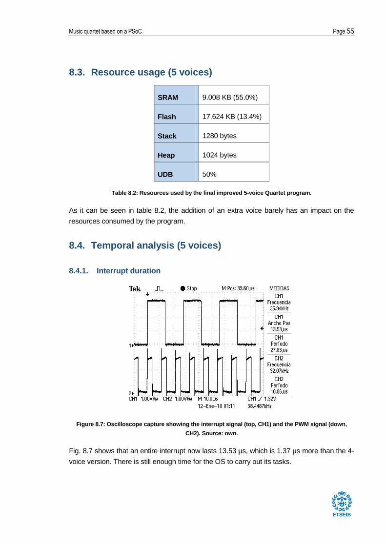
8.4.1. Interrupt duration
Figure 8.7: Oscilloscope capture showing the interrupt signal (top, CH1) and the PWM signal (down,
CH2). Source: own.
Fig. 8.7 shows that an entire interrupt now lasts 13.53 µs, which is 1.37 µs more than the 4-
voice version. There is still enough time for the OS to carry out its tasks.

Page 56 Report
9. Future improvements
In this chapter, suggestions for future improvements of the Quartet project will be
presented.
9.1. Bluetooth
One of the important features of the PSoC that has not been used in this project is its
capacity to communicate with external devices through Bluetooth. Such feature could be
used to send music sheets (in the form of a header file) from a smartphone to the PSoC
directly, for example.
9.2. Utilizing hardware blocks
As mentioned in chapter 3, one of the objectives of this project that could not be fulfilled
consisted in relieving the CPU by using the configurable hardware blocks to carry out some
of the necessary operations of the Quartet code. This would require a PSoC with the
following blocks:
- Waveform generators [25]: These would allow the characteristic waveforms of the
instruments to be generated with no CPU cost and without occupying ROM storage
space.
- Modulation block [26]: This block would carry out the multiplication between the
characteristic waveform and the amplitude envelope and would result in a significant
decrease in CPU usage. Another option is to use an analog multiplier [27].
- High resolution DACs [28]: These would replace the PWM blocks and would not
require an RC filter. The new analog output signal would thus be more pure.
9.3. Adding new instruments
In this project, a new voice has been added to the Quartet program. This could be taken a
step further, by adding a completely new instrument. However, it would require a certain
degree of musical knowledge (or experimentation with real instruments) in order to be able
to define its characteristic waveform and envelope.

Music quartet based on a PSoC Page 57
9.4. Multiple sound outputs
Another possible improvement would be to have separate sound outputs for every voice, so
that each of them could be heard on separate speakers. This would help create a more
realistic orchestral sensation, as well as allowing a higher bit resolution for every voice (their
samples would no longer have to be added together and divided).
Also related to this is the introduction of a stereo output, which would allow each speaker to
play different audio. This would allow voices to be panned either to the right or left, making
them easier to distinguish from one another.
9.5. Widening the range of note durations
Currently, the Quartet only offers 4 options for the note duration (1, 2, 3 and 4), where 1 is
an eight note and 4 is a half note. It is possible to create longer notes by using the
playmore() instruction, but shorter ones cannot be played.
Therefore, another improvement could be re-structuring the play() instruction so that it
allows a wider range of note durations, especially so that faster notes could be played.

Page 58 Report
10. Planning
July
W30 Prior works consulting
August
W32 C language learning
PSoC Creator 4.1 installation and testing
September
W35 C language learning
W36 Original Quartet code examination
W37-W38 FreeRTOS manual consulting
W39 FreeRTOS migration
October
W40 Quartet migration
W41 Quartet troubleshooting
W42-W43 PSoC 4 vs PIC18 comparison
November
W44 Temporal analysis
W45 Final migration corrections
Note frequency range broadening
W47 Introduction of the 16-bit PWM
December
W48 New amplitude envelopes
W49 Waveform tables with 128 and 256 data points
W50 Addition of the extra voice and extra octave
Table 10.1: Project planning

Music quartet based on a PSoC Page 59
11. Budget
Table 11.1: Project budget
Concept Units Unit price [€/unit] Total price [€]
CY8CKIT-042-BLE PSoC 4 kit 1 40.61 40.61
PSoC Creator 4.1 - 0.00 0.00
MPLAB IDE - 0.00 0.00
PuTTY - 0.00 0.00
PC 1 700.00 700.00
Work hours 277 40.00 11080.00
11820.61

Page 60 Report
12. Environmental impact
Cypress Semiconductor’s products comply with the RoHS directive (Restriction of
Hazardous Substances Directive) [29]. This means that the PSoC 4 does not include more
Lead, Mercury, Hexavalent Chromium, Cadmium, PBB and PBDE than the European Union
allows.
The project also has an acoustic impact, which can be dangerous to human hearing. This is
why an adequate resistance has to be selected for the RC filter, so that the audio’s volume
is within acceptable levels.
Therefore, it can be concluded that this project has a minimal impact on the environment.

Music quartet based on a PSoC Page 61
Conclusion
The objectives proposed at the start of the project have all been fulfilled at its completion.
Some expectations, such as those of the resulting sound quality, have even been
exceeded. The final program has a vastly improved sound quality, thanks to a significant
increase in bit resolution and the addition of more accurate waveforms and amplitude
envelopes. An extra octave, another voice and a wider note frequency range have also
been added successfully.
The project as a whole has contributed to:
- Learning how to use the PSoC Creator 4.1 IDE and a PSoC 4 microcontroller.
- Learning the C programming language and how to use it in a practical case.
- Learning how to troubleshoot a microcontroller application.
- Understanding how FreeRTOS works.
- Learning how an audio synthesizer works and how it can be improved.

Page 62 Report
Bibliography
[1] Victor Timofeev, OSA RTOS, [http://www.picosa.narod.ru/].
[2] Pere Domenech, Aplicaciones musicales del sistema operativo en tiempo real OSA
RTOS, Barcelona 2015.
[3] Pau Mendieta, Audio application based on FreeRTOS Operating System, Barcelona
2017.
[4] Real Time Engineers Ltd., FreeRTOS Official Website,
[http://www.freertos.org/RTOS.html]
[5] Juan Gallostra, RF Music Festival: orquesta basada en microcontroladores PIC18 y
RF, Barcelona 2015.
[6] Joan Calvet, CAN Music Festival: orquesta basada en microcontroladores PIC18 y
bus CAN, Barcelona 2016.
[7] Tutorials Point, C programming, [https://www.tutorialspoint.com/cprogramming/, consulted on August 2017].
[8] Cypress Semiconductor Corporation, Official PSoC Creator Website, [http://www.cypress.com/products/psoc-creator-integrated-design-environment-ide]
[9] Cypress Semiconductor Corporation, Pulse Width Modulator (PWM) 3.30 Component Datasheet, 2016.
[10] Cypress Semiconductor Corporation, PSoC 4 Timer Counter Pulse Width Modulator (TCPWM) 2.10 Component Datasheet, 2016.
[11] Cypress Semiconductor Corporation, PSoC 4 Serial Communication Block (SCB) 4.0 Component Datasheet, 2017.
[12] Cypress Semiconductor Corporation, Clock 2.20 Component Datasheet, 2017.
[13] Cypress Semiconductor Corporation, Interrupt 1.70 Component Datasheet, 2017.
[14] Cypress Semiconductor Corporation, Pins 2.20 Component Datasheet, 2017.
[15] Cypress Semiconductor Corporation, CY8CKIT-042-BLE Quick Start Guide, 2015.
[16] Real Time Engineers Ltd., Mastering the FreeRTOS™ Real Time Kernel, 2016.
[17] Cypress Semiconductor Corporation, Free RTOS with PSoC 4 BLE, [https://cypress.hackster.io/42177/free-rtos-with-psoc-4-ble-82a61e, consulted on August 2017]
[18] Cypress Semiconductor Corporation, TCPWM (PWM mode) example project 2.0,

Music quartet based on a PSoC Page 63
2016.
[19] Alan Hawse, Implementing PSoC Printf, [https://iotexpert.com/2017/05/10/implementing-psoc-printf/, consulted on October 2017]
[20] Simon Tatham, PuTTY, [http://www.putty.org/, consulted on October 2017]
[21] MICROCHIP TECHNOLOGY INC. MPLAB IDE. [http://www.microchip.com/pagehandler/en-us/family/mplabx/].
[22] Cypress Semiconductor Corporation, TCPWM (Timer/Counter mode) example project 3.0, 2016.
[23] Real Time Engineers Ltd., The FreeRTOS™ Reference Manual, 2016.
[24] Ganesh Raaja, HIGH RESOLUTION HIGH FREQUENCY PWM IN PSOC4 BLE, [http://www.cypress.com/blog/psoc-hacker-blog/high-resolution-high-frequency-pwm-psoc4-ble, consulted on November 2017].
[25] Cypress Semiconductor Corporation, AN69133 - PSoC® 3 / PSoC 5LP Easy Waveform Generation with the WaveDAC8 Component, [http://www.cypress.com/documentation/application-notes/an69133-psoc-3-psoc-5lp-easy-waveform-generation-wavedac8-component, consulted on January 2018].
[26] Cypress Semiconductor Corporation, AN62582 - AM Modulation and Demodulation, [http://www.cypress.com/documentation/application-notes/an62582-am-modulation-and-demodulation, consulted on January 2018].
[27] Victor Kremin, Analog Multiplication with PSoC, 2010.
[28] Cypress Semiconductor Corporation, High Resolution DAC in PSoC 3/5, [https://community.cypress.com/docs/DOC-12231, consulted on January 2018].
[29] Cypress Semiconductor Corporation, RoHS, Green and Environmental Information, [http://www.cypress.com/support/rohs, consulted on January 2018].